JP2008043503A - Detaching instrument - Google Patents
Detaching instrument Download PDFInfo
- Publication number
- JP2008043503A JP2008043503A JP2006221401A JP2006221401A JP2008043503A JP 2008043503 A JP2008043503 A JP 2008043503A JP 2006221401 A JP2006221401 A JP 2006221401A JP 2006221401 A JP2006221401 A JP 2006221401A JP 2008043503 A JP2008043503 A JP 2008043503A
- Authority
- JP
- Japan
- Prior art keywords
- protector
- needle hub
- needle
- tip
- base
- Prior art date
- Legal status (The legal status is an assumption and is not a legal conclusion. Google has not performed a legal analysis and makes no representation as to the accuracy of the status listed.)
- Pending
Links
Images


Classifications
-
- A—HUMAN NECESSITIES
- A61—MEDICAL OR VETERINARY SCIENCE; HYGIENE
- A61M—DEVICES FOR INTRODUCING MEDIA INTO, OR ONTO, THE BODY; DEVICES FOR TRANSDUCING BODY MEDIA OR FOR TAKING MEDIA FROM THE BODY; DEVICES FOR PRODUCING OR ENDING SLEEP OR STUPOR
- A61M5/00—Devices for bringing media into the body in a subcutaneous, intra-vascular or intramuscular way; Accessories therefor, e.g. filling or cleaning devices, arm-rests
- A61M5/178—Syringes
- A61M5/31—Details
- A61M5/32—Needles; Details of needles pertaining to their connection with syringe or hub; Accessories for bringing the needle into, or holding the needle on, the body; Devices for protection of needles
- A61M5/3202—Devices for protection of the needle before use, e.g. caps
- A61M5/3204—Needle cap remover, i.e. devices to dislodge protection cover from needle or needle hub, e.g. deshielding devices
Landscapes
- Health & Medical Sciences (AREA)
- Vascular Medicine (AREA)
- Engineering & Computer Science (AREA)
- Anesthesiology (AREA)
- Biomedical Technology (AREA)
- Heart & Thoracic Surgery (AREA)
- Hematology (AREA)
- Life Sciences & Earth Sciences (AREA)
- Animal Behavior & Ethology (AREA)
- General Health & Medical Sciences (AREA)
- Public Health (AREA)
- Veterinary Medicine (AREA)
- Infusion, Injection, And Reservoir Apparatuses (AREA)
Abstract
Description
本発明は、取り外し器具に関する。詳しくは、針に接触することなくプロテクターを外す事が可能な取り外し器具に関する。 The present invention relates to a removal instrument. More specifically, the present invention relates to a removal device that can remove the protector without contacting the needle.
注射や採血の目的に使用される翼状針や注射針は、一般的に注射針6と、この注射針6と連通する針ハブ7と、注射針6を保護するプロテクター8とから構成されている(図5参照)。
A winged needle or injection needle used for injection or blood collection is generally composed of an
プロテクターは、先端が閉塞した、先端へ向かって縮径する円錐台形状のものが一般的であり、針ハブにプロテクターの基端の開口部を嵌合させることによって針が剥き出しにならないように装着される。プロテクターを装着することにより、使用前に刃先を他のものに接触させてしまったり、医療従事者が誤って手指を刃先で穿刺してしまうこと(所謂、誤穿刺)を防止している。 The protector generally has a truncated cone shape with the tip closed and the diameter decreasing toward the tip, and it is attached so that the needle is not exposed by fitting the opening of the proximal end of the protector to the needle hub. Is done. By attaching the protector, the blade tip is brought into contact with another object before use, or a medical worker accidentally punctures a finger with the blade tip (so-called erroneous puncture).
しかし、針ハブからプロテクターを脱離させる際には、人間の手によって外しており、プロテクターに掛かる力の偏りが生じることがある。力の偏りが生じると、針の軸心に対してプロテクターの軸心がずれてしまい、プロテクターの内壁が針先に当たってしまうといったことがおきる。 However, when the protector is detached from the needle hub, it is removed by a human hand, and there may be a bias in the force applied to the protector. When the force is biased, the protector's axial center is displaced from the needle's axial center, and the inner wall of the protector hits the needle tip.
一般的に注射針の先端は極めて鋭利に仕上げられているため、前記したように、プロテクターの内壁が針先に接触すると、刃先が針の径方向に折れ曲がる、所謂、針先マクレが発生する虞が高い。針先マクレの生じた針は使用すると穿刺の際に激痛を伴うことがあり、患者のQOLを低下させる場合がある。 Generally, since the tip of the injection needle is finished extremely sharply, as described above, when the inner wall of the protector comes into contact with the needle tip, the blade tip may bend in the radial direction of the needle, so-called needle tip crack may occur. Is expensive. When a needle with a needle tip macule is used, it may be accompanied by severe pain at the time of puncture, which may reduce the patient's QOL.
したがって、マクレが生じないよう、針ハブからプロテクターを慎重に外すことが要求されるが、特に迅速な対応を必要とする医療現場にて注意を割くことは困難である。そこで、針ハブよりプロテクターを外す際に、針とプロテクターと内壁とが接触することのないようなプロテクターの取り外し器具が必要である。 Therefore, it is required to carefully remove the protector from the needle hub so as not to cause macules, but it is difficult to pay attention especially in a medical field that requires quick response. Therefore, when removing the protector from the needle hub, a protector removing device is required so that the needle, the protector, and the inner wall do not come into contact with each other.
本発明の目的は、針ハブよりプロテクターを外す際に、針先にプロテクター内壁が接触しない、プロテクターの取り外し器具を提供することにある。 An object of the present invention is to provide a protector removal device in which the protector inner wall does not contact the needle tip when the protector is removed from the needle hub.
そこで、本発明者らは、
(1)注射針を覆うプロテクターを取り外すための取り外し器具であって、針ハブの基端フランジと前記針ハブに嵌合するプロテクターの基端部とで形成された窪み部に挿入可能な厚みおよび間隔を有して平行に設けられた、一対の平板状の挿入部と、平行に設けられた前記挿入部の基端同士を連結する基部と、前記基部に、針ハブと針ハブに嵌合したプロテクターとが前記挿入部を移動するのを阻害しないように設けられた把持部とを含む取り外し器具。
(2)さらに、前記挿入部の先端に、基端から先端に向かって間隔が拡張し、前記挿入部の先端より厚みが厚くないように形成されたガイド部が設けられている、(1)に記載の取り外し器具。
(3)前記挿入部は、両面の延長が角度θで交わるように基端から先端方向へ向かって厚みが減少するよう形成されてなる、(1)または(2)に記載の取り外し器具。
(4)前記角度θは0度より大きく5度以下の範囲である、(3)に記載の取り外し器具。
(5)前記角度θは0度より大きく3度以下の範囲である、(3)または(4)に記載の取り外し器具。
を用いることにより、平板状の一対の挿入部がプロテクターを傾けることなくプロテクターと針ハブとの嵌合を外すことが可能であるため、針の軸心に対して、プロテクターの軸心を一致したまま針よりプロテクターを脱離可能とすることが可能であるので、針先にプロテクター内壁が接触しないため、針先マクレを生じることがない。
Therefore, the present inventors
(1) A removal tool for removing a protector that covers an injection needle, and a thickness that can be inserted into a recess formed by a proximal end flange of the needle hub and a proximal end portion of the protector that fits the needle hub, and A pair of flat plate-like insertion portions provided in parallel with a gap, a base portion that connects the base ends of the insertion portions provided in parallel, and a needle hub and a needle hub fitted into the base portion And a gripper provided so as not to hinder the movement of the protector by the protector.
(2) Furthermore, a guide portion is provided at the distal end of the insertion portion so that a distance is expanded from the proximal end toward the distal end and the thickness is not thicker than the distal end of the insertion portion. (1) Detachment device as described in.
(3) The insertion device according to (1) or (2), wherein the insertion portion is formed so that the thickness decreases from the proximal end toward the distal end so that the extension of both surfaces intersects at an angle θ.
(4) The removal tool according to (3), wherein the angle θ is in the range of greater than 0 degrees and less than or equal to 5 degrees.
(5) The removal instrument according to (3) or (4), wherein the angle θ is in the range of greater than 0 degrees and less than or equal to 3 degrees.
Since the pair of flat plate-like insertion parts can remove the fit between the protector and the needle hub without tilting the protector, the protector's axis is aligned with the needle's axis. Since it is possible to remove the protector from the needle as it is, the inner wall of the protector does not come into contact with the needle tip, so that there is no needle tip crack.
このように、本発明の取り外し器具は、針先にプロテクター内壁が接触することなく針ハブよりプロテクターを取り外すことが可能であるため、医療に好適に用いることができる。 Thus, since the protector can be removed from the needle hub without the protector inner wall coming into contact with the needle tip, the remover of the present invention can be suitably used for medical treatment.
以下、図を用いて本発明の取り外し器具を説明する。しかし、本願発明は、これら図面に記載した実施態様例に限定されるものではない。 Hereinafter, the removal tool of the present invention will be described with reference to the drawings. However, the present invention is not limited to the exemplary embodiments described in these drawings.
図1は本発明の取り外し器具についての一実施態様例の正面図及び横面図である。図2は本発明の取り外し器具の他の実施様態例の先端拡大正面図及ぶ横面図である。図3は本発明の取り外し器具の更に他の実施様態例の斜視図である。図4は図1に示される取り外し器具の使用方法の図である。図5は、一般的な注射用穿刺針の図である。 FIG. 1 is a front view and a side view of an embodiment of the removal tool of the present invention. FIG. 2 is an enlarged front view and a lateral view of the distal end of another embodiment of the removal tool of the present invention. FIG. 3 is a perspective view of still another embodiment of the removal tool of the present invention. FIG. 4 is a diagram of a method of using the removal tool shown in FIG. FIG. 5 is a diagram of a general injection puncture needle.
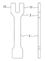
図1は、挿入部11,12、基部2、把持部3とからなる取り外し器具である。同形状の一対のI字型の平板である挿入部11,12が平行に設けられ、それぞれの挿入部の基端は、V字型の平板である基部2の先端側である、V字の二股部分に連結されている。この時、隣り合う挿入部の間隔は、針ハブのフランジと針ハブに嵌合したプロテクターの基端部とで形成される窪み部に、挿入部を挟み込むようなかたちで挿入可能であればよく、挿入部と窪み部とが接触して挿入されてもよいし、挿入部が窪み部に遊挿されてもよい。基部2の基端には把持部3が設けられている。
FIG. 1 shows a detachment tool including
挿入部を同形状とし、窪み部に挿入可能な間隔に形成されている事で、プロテクターを針ハブより外す際には、挿入部はプロテクター基端面周上の軸心に対して対称位置である直径部分にあたる2点に力を与え、一点に力が掛かるということがないため、プロテクターが傾いてプロテクターの内壁が針先に接触するということがなく、針先マクレが生じることがない。 When the protector is removed from the needle hub, the insertion part is symmetrical with respect to the axis on the periphery of the protector base end surface. Since force is not applied to two points corresponding to the diameter portion and no force is applied to one point, the protector does not tilt and the inner wall of the protector does not contact the needle tip, and the needle tip macule does not occur.
図2は本発明の取り外し器具の他の実施様態例である。挿入部の先端に、基端から先端に向かって間隔が拡張するガイド部41,42が設けられている(a>b)。この時、ガイド部先端の間隔aは、窪み部に遊挿される距離であることが好ましい。ガイド部を設けることによって、挿入部の間隔bが、窪み部の直径と同一である場合においても、挿入部の窪み部への挿入がよりスムーズに行うことが可能である。
FIG. 2 shows another embodiment of the removal device of the present invention.
また、挿入部の厚みを基端から先端に向かって、平板の両面の延長が角度θで交わるように薄く成形することによって、より挿入しやすくなる。θの範囲は0度より大きく5度以下である範囲に形成するのが好ましく、さらに好ましくは0度より大きく3度以下である範囲に成形するのがよい。上記範囲で薄くすることによって、取り外し器具そのものの強度を脆くすることなく、より挿入がスムーズとなるからである。挿入部の先端にガイド部を設ける場合、ガイド部の厚みは挿入部の先端よりも厚くならなければよく、挿入部と同様に、両面の延長が基端から先端へ向かって角度θで減少するよう形成してもよい。 Further, by inserting the thickness of the insertion portion so that the extension of both sides of the flat plate intersects at an angle θ from the proximal end to the distal end, insertion becomes easier. The range of θ is preferably formed in a range greater than 0 degree and not greater than 5 degrees, and more preferably in a range greater than 0 degree and not greater than 3 degrees. This is because by making the thickness within the above range, insertion becomes smoother without weakening the strength of the removal tool itself. When the guide portion is provided at the distal end of the insertion portion, the thickness of the guide portion does not have to be thicker than the distal end of the insertion portion. Like the insertion portion, the extension of both surfaces decreases from the proximal end to the distal end at an angle θ. You may form so.
基部2の形状は、平行に設けられた一対の挿入部の基端同士を連結し、取り外し器具の使用に際して邪魔にならないものであれば、形状は特に限定されるものではなく、図1及び図2に示されるようにV字型であっても良いし、矩形型でもよい。基部の厚みについても、挿入部と同じでも、挿入部に対して厚くても薄くてもよく、特に限定されない。
The shape of the
把持部3の設ける位置や形状は、針ハブよりプロテクターを外す際に、ガイド部及び挿入部をプロテクターの嵌合した針ハブが移動するのを妨害しないものであれば特に限定されない。
The position and shape of the
挿入部11,12、基部2、把持部3、ガイド部41,42は、別体で形成されても一体に成形されてもよい。特に一体に形成されている場合は、破損や部品の脱落等が生じにくいため好ましい。本発明の取り外し器具を形成する材質は、針ハブよりプロテクターを外す力によって破損したり変形したりしないものであれば特に限定されず、このようなものとしては、ポリエチレン、ポリプロピレン、PET、ナイロン、ABS樹脂等の各種プラスチック素材や、ステンレス等の金属素材等が挙げられる。
The
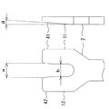
本発明の更に他の実施例を、図3に示す。図3に示す取り外し器具は、天面が図1または図2に見られるような、挿入部11,12と基部2とガイド部41,42とから形成され、その下部には有底の円筒状の把持部3が設けられている。把持部は、挿入部にプロテクターが嵌合している針ハブが移動するのを妨げないよう、ガイド部の下方にあたる位置が切り取られた形状となっている。このような形状では、例えば机上などに載置し、プロテクターが嵌合した針ハブの窪み部を差し込み、把持部を掴みながら上方に引き抜くことでプロテクターが把持部内に落下し、外すことが可能となる。従って、針ハブより取り外されたプロテクターを廃棄・収集可能であり、プロテクターが散乱することを防ぐことが可能である。
Yet another embodiment of the present invention is shown in FIG. The removal tool shown in FIG. 3 is formed of
図4を用いて、図1に示される取り外し器具の使用方法について説明する。シリンジに装着された、プロテクターが嵌合した針ハブの基端のフランジとプロテクター基端開口部によって形成された窪み部Aに挿入部21,22をスライドさせるように挿入し、針ハブが基端部と当接するまで挿入部を挿入する。この状態で、針ハブと基端部とが当接する位置を支点として把持部をシリンジ側に引き寄せるとプロテクターが針ハブから脱離する。この時、取り外し器具はプロテクター基端面周上の軸心に対して対称位置である直径部分にあたる2点に均等に力を与え、嵌合が外れるため、針の軸心とプロテクターの軸心とがずれることなく脱離させることが可能であるので、針先とプロテクター内壁は接触しないので、針先マクレを生じることなくプロテクターを針ハブから脱離できる。 A method of using the removal tool shown in FIG. 1 will be described with reference to FIG. The needle hub is inserted into the recess A formed by the flange of the proximal end of the needle hub fitted with the protector and fitted with the protector, and the opening of the protector proximal end so that the needle hub slides. Insert the insertion part until it comes into contact with the part. In this state, when the gripping part is pulled toward the syringe with the position where the needle hub and the proximal end abut as a fulcrum, the protector is detached from the needle hub. At this time, the removal tool applies a force equally to two points corresponding to the diameter portion that is symmetrical with respect to the axis on the circumference of the protector base end surface, and the fitting is released, so that the axis of the needle and the axis of the protector are separated. Since the needle tip and the inner wall of the protector are not in contact with each other without being displaced, the protector can be detached from the needle hub without causing needle tip cracks.
本発明は、上述のように、針先にプロテクター内壁が接触することなく針ハブよりプロテクターを取り外すことが可能であるため、医療に好適に用いることができる。 Since the protector can be removed from the needle hub without contacting the inner wall of the protector with the needle tip as described above, the present invention can be suitably used for medical treatment.
11,12 挿入部
2 基部
3 把持部
41,42 ガイド部
6 注射針
7 針ハブ
8 プロテクター
A 窪み部
11, 12
6
Claims (5)
針ハブの基端フランジと前記針ハブに嵌合するプロテクターの基端部とで形成された窪み部に挿入可能な厚みおよび間隔を有して平行に設けられた、一対の平板状の挿入部と、
平行に設けられた前記挿入部の基端同士を連結する基部と、
前記基部に、針ハブと針ハブに嵌合したプロテクターとが前記挿入部を移動するのを阻害しないように設けられた把持部とを含む、
取り外し器具。 A removal device for removing the protector covering the injection needle,
A pair of flat plate-like insertion portions provided in parallel with a thickness and a space that can be inserted into a recess formed by a proximal flange of the needle hub and a proximal end portion of a protector fitted to the needle hub. When,
A base for connecting base ends of the insertion portions provided in parallel;
The base includes a gripping portion provided so as not to inhibit the needle hub and a protector fitted to the needle hub from moving the insertion portion.
Remover.
Priority Applications (1)
| Application Number | Priority Date | Filing Date | Title |
|---|---|---|---|
| JP2006221401A JP2008043503A (en) | 2006-08-15 | 2006-08-15 | Detaching instrument |
Applications Claiming Priority (1)
| Application Number | Priority Date | Filing Date | Title |
|---|---|---|---|
| JP2006221401A JP2008043503A (en) | 2006-08-15 | 2006-08-15 | Detaching instrument |
Publications (1)
| Publication Number | Publication Date |
|---|---|
| JP2008043503A true JP2008043503A (en) | 2008-02-28 |
Family
ID=39177827
Family Applications (1)
| Application Number | Title | Priority Date | Filing Date |
|---|---|---|---|
| JP2006221401A Pending JP2008043503A (en) | 2006-08-15 | 2006-08-15 | Detaching instrument |
Country Status (1)
| Country | Link |
|---|---|
| JP (1) | JP2008043503A (en) |
Cited By (3)
| Publication number | Priority date | Publication date | Assignee | Title |
|---|---|---|---|---|
| JP2012502754A (en) * | 2008-09-18 | 2012-02-02 | ベクトン・ディキンソン・アンド・カンパニー | Container for an injection device having an injection needle |
| JP2014036879A (en) * | 2013-10-18 | 2014-02-27 | Abbott Japan Co Ltd | Self-injection aid, and self-injection system |
| JP2017504429A (en) * | 2014-02-04 | 2017-02-09 | サノフィ−アベンティス・ドイチュラント・ゲゼルシャフト・ミット・ベシュレンクテル・ハフツング | Sheath removal mechanism |
Citations (3)
| Publication number | Priority date | Publication date | Assignee | Title |
|---|---|---|---|---|
| JPS51160997U (en) * | 1975-06-17 | 1976-12-21 | ||
| JPH11206883A (en) * | 1998-01-30 | 1999-08-03 | Jms Co Ltd | Injection needle extractor and dumping device using the same |
| JP2003000658A (en) * | 2001-06-22 | 2003-01-07 | Koichiro Abe | Assisting tool for disposable syringe |
-
2006
- 2006-08-15 JP JP2006221401A patent/JP2008043503A/en active Pending
Patent Citations (3)
| Publication number | Priority date | Publication date | Assignee | Title |
|---|---|---|---|---|
| JPS51160997U (en) * | 1975-06-17 | 1976-12-21 | ||
| JPH11206883A (en) * | 1998-01-30 | 1999-08-03 | Jms Co Ltd | Injection needle extractor and dumping device using the same |
| JP2003000658A (en) * | 2001-06-22 | 2003-01-07 | Koichiro Abe | Assisting tool for disposable syringe |
Cited By (5)
| Publication number | Priority date | Publication date | Assignee | Title |
|---|---|---|---|---|
| JP2012502754A (en) * | 2008-09-18 | 2012-02-02 | ベクトン・ディキンソン・アンド・カンパニー | Container for an injection device having an injection needle |
| US8728028B2 (en) | 2008-09-18 | 2014-05-20 | Becton Dickinson And Company | Container for injection device with injection needle |
| US10143808B2 (en) | 2008-09-18 | 2018-12-04 | Becton, Dickinson And Company | Container for injection device with injection needle |
| JP2014036879A (en) * | 2013-10-18 | 2014-02-27 | Abbott Japan Co Ltd | Self-injection aid, and self-injection system |
| JP2017504429A (en) * | 2014-02-04 | 2017-02-09 | サノフィ−アベンティス・ドイチュラント・ゲゼルシャフト・ミット・ベシュレンクテル・ハフツング | Sheath removal mechanism |
Similar Documents
| Publication | Publication Date | Title |
|---|---|---|
| JP5719371B2 (en) | Catheter device | |
| JP4171478B2 (en) | Endoscope plug | |
| JP5453284B2 (en) | Protective equipment | |
| JP2013505098A5 (en) | ||
| US20060009711A1 (en) | End effector assembly cap and tissue removal device and related methods | |
| EP1800607B1 (en) | Reinforcing tool for a medical needle | |
| US20070016148A1 (en) | Winged needle assembly | |
| JP2015509006A (en) | Catheter having a removable cannula for piercing a body cavity, and a cannula for use with a catheter movable within the cannula | |
| JP2009058260A (en) | Swab shank | |
| JP4383473B2 (en) | Endoscope plug | |
| JP2008043503A (en) | Detaching instrument | |
| JP5246394B2 (en) | Clip, clip unit and clip device | |
| US20130045135A1 (en) | Grommet Device with Pull-Tab and Associated Methods Thereof | |
| US20110106142A1 (en) | Suturing instruments and suturing systems | |
| JP2009189386A (en) | Implement for assisting introduction of guide wire into catheter | |
| AU2018311912B2 (en) | Cannula holder | |
| WO2019146806A1 (en) | Ear treatment instrument | |
| JP6324013B2 (en) | Cannula | |
| JP2006304966A (en) | Trocar equipped with ring-shaped member | |
| JP6581889B2 (en) | Guide wire insertion aid | |
| JP2008194112A (en) | Medical puncture needle | |
| JP4098972B2 (en) | Endoscopic clip device | |
| JP5618953B2 (en) | Forceps plug and endoscope | |
| JP4254910B2 (en) | Guide wire introduction aid and catheter equipped therewith | |
| WO2009142158A1 (en) | Kit for exfoliating scab and medical needle |
Legal Events
| Date | Code | Title | Description |
|---|---|---|---|
| A621 | Written request for application examination |
Free format text: JAPANESE INTERMEDIATE CODE: A621 Effective date: 20090327 |
|
| A131 | Notification of reasons for refusal |
Free format text: JAPANESE INTERMEDIATE CODE: A131 Effective date: 20110215 |
|
| A977 | Report on retrieval |
Free format text: JAPANESE INTERMEDIATE CODE: A971007 Effective date: 20110217 |
|
| A02 | Decision of refusal |
Free format text: JAPANESE INTERMEDIATE CODE: A02 Effective date: 20110712 |