JP2008043124A - Magnet generator - Google Patents
Magnet generator Download PDFInfo
- Publication number
- JP2008043124A JP2008043124A JP2006216711A JP2006216711A JP2008043124A JP 2008043124 A JP2008043124 A JP 2008043124A JP 2006216711 A JP2006216711 A JP 2006216711A JP 2006216711 A JP2006216711 A JP 2006216711A JP 2008043124 A JP2008043124 A JP 2008043124A
- Authority
- JP
- Japan
- Prior art keywords
- magnet
- flywheel
- permanent magnet
- permanent
- magnet generator
- Prior art date
- Legal status (The legal status is an assumption and is not a legal conclusion. Google has not performed a legal analysis and makes no representation as to the accuracy of the status listed.)
- Granted
Links
Images


Classifications
-
- H—ELECTRICITY
- H02—GENERATION; CONVERSION OR DISTRIBUTION OF ELECTRIC POWER
- H02K—DYNAMO-ELECTRIC MACHINES
- H02K1/00—Details of the magnetic circuit
- H02K1/06—Details of the magnetic circuit characterised by the shape, form or construction
- H02K1/22—Rotating parts of the magnetic circuit
- H02K1/27—Rotor cores with permanent magnets
- H02K1/2786—Outer rotors
- H02K1/2787—Outer rotors the magnetisation axis of the magnets being perpendicular to the rotor axis
- H02K1/2789—Outer rotors the magnetisation axis of the magnets being perpendicular to the rotor axis the rotor consisting of two or more circumferentially positioned magnets
- H02K1/2791—Surface mounted magnets; Inset magnets
-
- Y—GENERAL TAGGING OF NEW TECHNOLOGICAL DEVELOPMENTS; GENERAL TAGGING OF CROSS-SECTIONAL TECHNOLOGIES SPANNING OVER SEVERAL SECTIONS OF THE IPC; TECHNICAL SUBJECTS COVERED BY FORMER USPC CROSS-REFERENCE ART COLLECTIONS [XRACs] AND DIGESTS
- Y10—TECHNICAL SUBJECTS COVERED BY FORMER USPC
- Y10T—TECHNICAL SUBJECTS COVERED BY FORMER US CLASSIFICATION
- Y10T29/00—Metal working
- Y10T29/49—Method of mechanical manufacture
- Y10T29/49002—Electrical device making
- Y10T29/49009—Dynamoelectric machine
- Y10T29/49012—Rotor
-
- Y—GENERAL TAGGING OF NEW TECHNOLOGICAL DEVELOPMENTS; GENERAL TAGGING OF CROSS-SECTIONAL TECHNOLOGIES SPANNING OVER SEVERAL SECTIONS OF THE IPC; TECHNICAL SUBJECTS COVERED BY FORMER USPC CROSS-REFERENCE ART COLLECTIONS [XRACs] AND DIGESTS
- Y10—TECHNICAL SUBJECTS COVERED BY FORMER USPC
- Y10T—TECHNICAL SUBJECTS COVERED BY FORMER US CLASSIFICATION
- Y10T29/00—Metal working
- Y10T29/49—Method of mechanical manufacture
- Y10T29/49002—Electrical device making
- Y10T29/4902—Electromagnet, transformer or inductor
- Y10T29/49071—Electromagnet, transformer or inductor by winding or coiling
-
- Y—GENERAL TAGGING OF NEW TECHNOLOGICAL DEVELOPMENTS; GENERAL TAGGING OF CROSS-SECTIONAL TECHNOLOGIES SPANNING OVER SEVERAL SECTIONS OF THE IPC; TECHNICAL SUBJECTS COVERED BY FORMER USPC CROSS-REFERENCE ART COLLECTIONS [XRACs] AND DIGESTS
- Y10—TECHNICAL SUBJECTS COVERED BY FORMER USPC
- Y10T—TECHNICAL SUBJECTS COVERED BY FORMER US CLASSIFICATION
- Y10T29/00—Metal working
- Y10T29/49—Method of mechanical manufacture
- Y10T29/49002—Electrical device making
- Y10T29/4902—Electromagnet, transformer or inductor
- Y10T29/49073—Electromagnet, transformer or inductor by assembling coil and core
-
- Y—GENERAL TAGGING OF NEW TECHNOLOGICAL DEVELOPMENTS; GENERAL TAGGING OF CROSS-SECTIONAL TECHNOLOGIES SPANNING OVER SEVERAL SECTIONS OF THE IPC; TECHNICAL SUBJECTS COVERED BY FORMER USPC CROSS-REFERENCE ART COLLECTIONS [XRACs] AND DIGESTS
- Y10—TECHNICAL SUBJECTS COVERED BY FORMER USPC
- Y10T—TECHNICAL SUBJECTS COVERED BY FORMER US CLASSIFICATION
- Y10T29/00—Metal working
- Y10T29/49—Method of mechanical manufacture
- Y10T29/49002—Electrical device making
- Y10T29/4902—Electromagnet, transformer or inductor
- Y10T29/49075—Electromagnet, transformer or inductor including permanent magnet or core
Abstract
Description
この発明は、フライホイールの回転により永久磁石と発電コイルとの電磁誘導作用により発電する磁石発電機に関するものである。 The present invention relates to a magnet generator that generates power by electromagnetic induction between a permanent magnet and a power generation coil by rotation of a flywheel.
従来、回転軸線の回りを回転する椀状のフライホイールと、このフライホイールの内周壁面に面接触して固定された複数個の弓形形状の永久磁石と、この永久磁石の内側に設けられ、径方向外側に突出した複数のティースを有する固定子鉄心と、各前記ティースに導線が巻回されて構成された発電コイルとを備えた磁石発電機が知られている(例えば、特許文献1参照)。 Conventionally, a bowl-shaped flywheel that rotates around the rotation axis, a plurality of arcuate permanent magnets fixed in surface contact with the inner peripheral wall surface of the flywheel, and provided inside the permanent magnets, 2. Description of the Related Art A magnet generator including a stator core having a plurality of teeth protruding radially outward and a power generation coil formed by winding a conductive wire around each of the teeth is known (see, for example, Patent Document 1). ).
上記磁石発電機では、弓形形状の永久磁石を製造するためには、切削や研磨加工を必要とし、永久磁石の製造に要する加工工数が多く、また加工時に多くの取代を必要とするためにそれだけ永久磁石の素材量が多くなってしまう。 In the above-mentioned magnet generator, in order to manufacture an arcuate permanent magnet, cutting and polishing are required, and many man-hours are required for manufacturing the permanent magnet. The amount of material of the permanent magnet will increase.
また、近年、磁石発電機は高出力化の傾向にあり、永久磁石(磁極)の多極化による高周波化、及び永久磁石体積の増加による高磁力化により、1台当りに使用する永久磁石の使用量(素材量)が増大し、永久磁石の、加工工数及び加工時の取代と相俟って、永久磁石のコストが嵩み、製品コストが増大してしまうという問題点があった。 In recent years, magnet generators have been trending toward higher output, and the amount of permanent magnets used per unit has been increased by increasing the frequency by increasing the number of permanent magnets (magnetic poles) and increasing the magnetic force by increasing the volume of permanent magnets. (Material amount) increases, and coupled with the processing time and machining allowance of the permanent magnet, there is a problem that the cost of the permanent magnet increases and the product cost increases.
この発明は、上記のような問題点を解決することを課題とするものであって、1台当りに使用する永久磁石の、加工工数及び使用量(素材量)を低減した磁石発電機を得ることを目的とする。 An object of the present invention is to solve the above-described problems, and to obtain a magnet generator that reduces the number of processing steps and the amount of use (material amount) of permanent magnets used per unit. For the purpose.
この発明に係る磁石発電機では、回転軸線の回りを回転する椀状のフライホイールと、このフライホイールの内周壁面に固定された複数個の永久磁石と、この永久磁石の内側に設けられ、径方向外側に突出した複数のティースを有する固定子鉄心と、各前記ティースに導線が巻回されて構成された発電コイルとを備えている磁石発電機において、前記永久磁石は、直方体形状の磁石本体が分割されて径方向に延びた分割面を有する複数個の磁石片で構成されている。 In the magnet generator according to the present invention, a bowl-shaped flywheel that rotates around the rotation axis, a plurality of permanent magnets fixed to the inner peripheral wall surface of the flywheel, and provided inside the permanent magnet, A magnet generator comprising a stator core having a plurality of teeth protruding radially outward and a power generation coil formed by winding a conductive wire around each of the teeth, wherein the permanent magnet is a rectangular parallelepiped magnet The main body is divided into a plurality of magnet pieces having divided surfaces extending in the radial direction.
この発明に係る磁石発電機によれば、1台当りに使用する永久磁石の、加工工数及び使用量(素材量)を低減することができる。 According to the magnet generator according to the present invention, it is possible to reduce the number of processing steps and the amount of use (material amount) of the permanent magnets used per unit.
以下、この発明の各実施の形態について図に基づいて説明するが、各図において同一、または相当部材、部位については、同一符号を付して説明する。 Hereinafter, embodiments of the present invention will be described with reference to the drawings. In the drawings, the same or corresponding members and parts will be described with the same reference numerals.
実施の形態1.
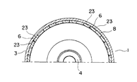
図1はこの発明の実施の形態1による磁石発電機を示す正面図、図2は図1の磁石発電機の側断面図、図3は図1の回転子1の部分正断面図、図4は図3の回転子の側断面図である。
この磁石発電機は、内燃機関と連結される回転子1と、この回転子1の内側に設けられブラケット(図示せず)に取り付けられる固定子2を備えている。
回転子1は、内燃機関により回転駆動される回転軸(図示せず)にボス部4で連結される椀状のフライホイール3と、このフライホイール3の内周壁面に周方向に間隔と空けて設けられた永久磁石6と、各永久磁石6の内側に密着した筒状の保護環7と、この保護環7及び各永久磁石6を一体にするとともにフライホイール3の内周壁面に固定するモールド成形材8とを備えている。
Embodiment 1 FIG.
1 is a front view showing a magnet generator according to Embodiment 1 of the present invention, FIG. 2 is a side sectional view of the magnet generator of FIG. 1, FIG. 3 is a partial front sectional view of the rotor 1 of FIG. FIG. 4 is a side sectional view of the rotor of FIG. 3.
The magnet generator includes a rotor 1 connected to an internal combustion engine, and a
The rotor 1 includes a bowl-
固定子2は、中空円柱状の固定子鉄心10及び3相の発電コイル9を有する。固定子鉄心10の外周部には、径外側方向に放射状に周方向に等分間隔で突出した各ティース11が形成されている。
外周部に複数個のティース11が形成された固定子鉄心10は、冷間圧延鋼板である中空の薄板磁性鋼板を回転軸線の方向に沿って多数枚積層して構成された積層鉄心12と、この積層鉄心12の両側面にそれぞれ密着して重ねられた、第1の端板13及び第2の端板14とから構成されている。
中空状で冷間圧延鋼板等により構成された、第1の端板13及び第2の端板14は、発電コイル9を保持するために外周縁部が発電コイル9側に折曲されている。
第1の端板13、第2の端板14及び積層鉄心12には、回転軸線と平行に貫通した貫通孔15が3カ所形成されている。この貫通孔15に貫通したボルト(図示せず)及びボルトの端部に螺着されたナット(図示せず)により、積層鉄心12と、第1の端板13及び第2の端板14とが一体化されている。
The
A
The
The
発電コイル9は、固定子鉄心10のティース11の周側面に、それぞれ表面がエナメル被膜された導線が巻回されて構成され、導線が巻回された周側面には、エポキシ系パウダ塗装の絶縁材16が被覆されている。
固定子鉄心10から延出した、発電コイル9の各相の口出し線17は、第1の保護チューブ18で被覆されている。各相の口出し線17は、第1の保護チューブ18内で、電気機器(図示せず)へ導出するためのリード線19とそれぞれ電気的に接続されている。固定子2の接線方向に延出したリード線19は、第2の保護チューブ20で被覆されている。
The
A
永久磁石6は、図5に示すように、希土類磁石からなる直方体形状の磁石本体21を中央部で分割して径方向に延びた分割面22を有する一対の磁石片23で構成されている。
各永久磁石6は、内径側がN極、外径側がS極の永久磁石6と、内径側がS極、外径側がS極の永久磁石6とが周方向に交互に配列されている。このように、複数個の永久磁石6は、隣接する永久磁石6が互いに逆極性に着磁されており、回転子1の内側空間では、交互に方向が変化する磁界を発生するようになっている。
As shown in FIG. 5, the
In each
上記構成の磁石発電機では、内燃機関により回転駆動される回転軸に連動してフライホイ−ル3が回転し、その際に永久磁石6により生じる交番磁界により、発電コイル9には電力が生じる。この際の交流出力は、図示しない整流用ダイオードにより整流され、車載バッテリ等に給電される。
In the magnet generator configured as described above, the
上記構成の磁石発電機によれば、永久磁石6は、直方体形状の磁石本体21を中央部で分割して径方向に延びた分割面22を有する一対の磁石片23で構成されているので、図6に示すように、直方体形状の磁石本体21を切削加工して弓形形状の永久磁石24を製造する場合と比べて、形状が簡素であるため、加工工数を低減でき、また加工時の取代を少なくできるために永久磁石の使用量(素材量)の低減が可能となる。
According to the magnet generator configured as described above, the
また、図7に示すように、フライホイール3と永久磁石6との間の隙間(g)は、直方体形状の磁石本体21を分割せずに用いた場合のフライホイール3と磁石本体21との間の隙間(G)と比較して大幅に小さくすることができ、磁気的な損失を低減することができる。
また、永久磁石6を用いた場合の保護環7の内周半径(r)は、磁石本体21を用いた場合の保護環7の内周半径(R)と比較して大きくできるため、フライホイール3の内側に位置する固定子2のスペース確保(例えば発電コイル9の巻線スペースの確保等)が容易になる。
Further, as shown in FIG. 7, the gap (g) between the
Further, the inner peripheral radius (r) of the
実施の形態2.
図8はこの発明の実施の形態2による磁石発電機の回転子1の部分正断面図である。
この実施の形態では、図9に示すように、磁石本体21の上側表面に、スリット25が形成されている。
他の構成は、実施の形態1と同じである。
FIG. 8 is a partial front sectional view of a rotor 1 of a magnet generator according to
In this embodiment, as shown in FIG. 9, a
Other configurations are the same as those of the first embodiment.
この実施の形態による磁石発電機によれば、磁石本体21に予めスリット25が形成されているので、磁石本体21を2分割する際には、このスリット25を基点として磁石本体21は分割され、磁石本体21を所定の部位から分割できるという効果がある。
According to the magnet generator according to this embodiment, since the
実施の形態3.
図10はこの発明の実施の形態3による磁石発電機の回転子1の部分正断面図である。
この実施の形態では、図11に示すように、磁石本体21の下側表面に、スリット26が形成されている。
他の構成は、実施の形態1と同じである。
FIG. 10 is a partial front sectional view of a rotor 1 of a magnet generator according to
In this embodiment, as shown in FIG. 11, a
Other configurations are the same as those of the first embodiment.
この実施の形態による磁石発電機によれば、磁石本体21に予めスリット26が形成されているので、磁石本体21を2分割する際には、このスリット26を基点として磁石本体21は分割され、磁石本体21を所定の部位から分割できるという効果がある。
なお、磁石本体21の上側及び下側の両面に、スリットを形成するようにしてもよい。
また、磁石本体21の側面にスリットを形成してもよいし、磁石本体21の全周に渡ってスリットを形成してもよい。
According to the magnet generator according to this embodiment, since the
Note that slits may be formed on both the upper and lower surfaces of the
Moreover, a slit may be formed on the side surface of the
実施の形態4.
図12はこの発明の実施の形態4による磁石発電機の回転子1の部分正断面図である。
この実施の形態では、フライホイール27の内周壁面は、多角形状である。
他の構成は、実施の形態1の磁石発電機と同じである。
FIG. 12 is a partial front sectional view of a rotor 1 of a magnet generator according to
In this embodiment, the inner peripheral wall surface of the
Other configurations are the same as those of the magnet generator of the first embodiment.
この実施の形態によれば、図13に示すように、フライホイール27と磁石片23との間の隙間を零にすることができ、磁気的な損失を低減することができ、出力電流を向上させることができるとともに、フライホイール27が回転する際の永久磁石6の回り止めとしての機能を有する。
According to this embodiment, as shown in FIG. 13, the gap between the
なお、上記各実施の形態では、永久磁石6は、磁石本体21を2分割した一対の磁石片23で構成されているが、勿論3分割以上分割した3個以上の磁石片で構成されていてもよい。
また、永久磁石6は、希土類磁石に限定されるものではなく、例えばフェライト磁石であってもよい。
また、上記各実施の形態では、モールド成形材8により、永久磁石6及び保護環7をフライホイール3,26に固定したが、その他の固定手段として、例えばフライホイールの開口部に形成されたかしめ部をかしめて永久磁石6を固定する手段、あるいはフライホイールの内周面に永久磁石6を接着して固定する手段であってもよい。
In each of the above embodiments, the
The
In each of the above embodiments, the
1 回転子、2 固定子、3,27 フライホイール、6,24 永久磁石、9 発電コイル、10 固定子鉄心、21 磁石本体、22 分割面、23 磁石片、25,26 スリット。 DESCRIPTION OF SYMBOLS 1 Rotor, 2 Stator, 3,27 Flywheel, 6,24 Permanent magnet, 9 Generator coil, 10 Stator iron core, 21 Magnet body, 22 Dividing surface, 23 Magnet piece, 25, 26 Slit.
Claims (3)
このフライホイールの内周壁面に固定された複数個の永久磁石と、
この永久磁石の内側に設けられ、径方向外側に突出した複数のティースを有する固定子鉄心と、
各前記ティースに導線が巻回されて構成された発電コイルと
を備えている磁石発電機において、
前記永久磁石は、直方体形状の磁石本体が分割されて径方向に延びた分割面を有する複数個の磁石片で構成されていることを特徴とする磁石発電機。 A bowl-shaped flywheel that rotates around a rotation axis;
A plurality of permanent magnets fixed to the inner peripheral wall surface of the flywheel;
A stator core provided inside the permanent magnet and having a plurality of teeth projecting radially outward;
In a magnet generator comprising a power generating coil configured by winding a conductive wire around each of the teeth,
The permanent magnet is composed of a plurality of magnet pieces each having a split surface extending in the radial direction by dividing a magnet body having a rectangular parallelepiped shape.
Priority Applications (4)
| Application Number | Priority Date | Filing Date | Title |
|---|---|---|---|
| JP2006216711A JP4312778B2 (en) | 2006-08-09 | 2006-08-09 | Magnet generator manufacturing method |
| DE102006057295A DE102006057295A1 (en) | 2006-08-09 | 2006-12-05 | Magnetoelectric generator |
| US11/702,224 US7586226B2 (en) | 2006-08-09 | 2007-02-05 | Magneto generator |
| US12/357,432 US8205321B2 (en) | 2006-08-09 | 2009-01-22 | Method of assembling a magneto generator |
Applications Claiming Priority (1)
| Application Number | Priority Date | Filing Date | Title |
|---|---|---|---|
| JP2006216711A JP4312778B2 (en) | 2006-08-09 | 2006-08-09 | Magnet generator manufacturing method |
Publications (2)
| Publication Number | Publication Date |
|---|---|
| JP2008043124A true JP2008043124A (en) | 2008-02-21 |
| JP4312778B2 JP4312778B2 (en) | 2009-08-12 |
Family
ID=38922198
Family Applications (1)
| Application Number | Title | Priority Date | Filing Date |
|---|---|---|---|
| JP2006216711A Expired - Fee Related JP4312778B2 (en) | 2006-08-09 | 2006-08-09 | Magnet generator manufacturing method |
Country Status (3)
| Country | Link |
|---|---|
| US (2) | US7586226B2 (en) |
| JP (1) | JP4312778B2 (en) |
| DE (1) | DE102006057295A1 (en) |
Cited By (5)
| Publication number | Priority date | Publication date | Assignee | Title |
|---|---|---|---|---|
| JP2009142081A (en) * | 2007-12-06 | 2009-06-25 | Toyota Motor Corp | Permanent magnet and method of manufacturing the same, and rotor and ipm motor |
| JP2009213259A (en) * | 2008-03-04 | 2009-09-17 | Mitsuba Corp | Magnet generator |
| WO2010038748A1 (en) * | 2008-10-02 | 2010-04-08 | 日産自動車株式会社 | Field pole magnet, field pole magnet manufacturing method, and permanent magnet rotary machine |
| JP2010183791A (en) * | 2009-02-09 | 2010-08-19 | Nissan Motor Co Ltd | Method of manufacturing split permanent magnet, and electric motor using split permanent magnet |
| JP2011147314A (en) * | 2010-01-18 | 2011-07-28 | Toyota Motor Corp | Rotor for ipm motor and method of manufacturing the same |
Families Citing this family (6)
| Publication number | Priority date | Publication date | Assignee | Title |
|---|---|---|---|---|
| JP2008199697A (en) * | 2007-02-08 | 2008-08-28 | Mitsubishi Electric Corp | Magnet generator |
| US7732961B2 (en) * | 2008-01-08 | 2010-06-08 | Lily Lin | Combined generator with built-in eddy-current magnetic resistance |
| JP5614096B2 (en) * | 2010-05-19 | 2014-10-29 | 日産自動車株式会社 | Permanent magnet embedded in rotor core of rotating electrical machine and method for manufacturing the same |
| CN102754307B (en) * | 2011-02-02 | 2015-05-06 | 丰田自动车株式会社 | Permanent magnet, motor rotor or stator, dynamo-electric machine |
| US9908255B2 (en) * | 2012-07-02 | 2018-03-06 | Nissan Motor Co., Ltd. | Apparatus and method for manufacturing magnet segments constituting field pole magnetic body |
| JP7263737B2 (en) * | 2018-10-30 | 2023-04-25 | 株式会社デンソー | Rotating electric machine |
Family Cites Families (24)
| Publication number | Priority date | Publication date | Assignee | Title |
|---|---|---|---|---|
| US3663850A (en) * | 1970-08-03 | 1972-05-16 | Phelon Co Inc | Field means for a dynamoelectric machine, magnet preassembly for use therein |
| JPS5443002B2 (en) | 1971-11-05 | 1979-12-18 | ||
| DE2212717A1 (en) * | 1972-03-16 | 1973-09-20 | Bosch Gmbh Robert | METHOD FOR MANUFACTURING PERMANENT FIELD MAGNETS FOR ELECTRICAL MACHINERY AND DEVICE FOR CARRYING OUT THE METHOD |
| DE2835441A1 (en) * | 1978-08-12 | 1980-02-28 | Vacuumschmelze Gmbh | Shell magnet of flat segments prodn. - uses starting, flat, magnetic plate, broken in mould into segments and embedded in suitable plastics substance |
| IT1131966B (en) * | 1980-07-22 | 1986-06-25 | Piaggio & C Spa | METHOD FOR THE MANUFACTURE OF A MAGNET FLYWHEEL AND FLYWHEEL OBTAINED |
| DE3673875D1 (en) * | 1985-06-06 | 1990-10-11 | Nippon Denso Co | MAGNETIC RUNNER. |
| JPH0681437B2 (en) * | 1987-05-19 | 1994-10-12 | 三菱電機株式会社 | Magnet generator |
| JPH01168543U (en) | 1988-05-16 | 1989-11-28 | ||
| JPH02107239U (en) | 1989-02-13 | 1990-08-27 | ||
| JP3152405B2 (en) * | 1992-06-10 | 2001-04-03 | オークマ株式会社 | Electric motor |
| US5783893A (en) * | 1995-10-20 | 1998-07-21 | Newport News Shipbuilding And Dry Dock Company | Multiple stator, single shaft electric machine |
| FR2742936B1 (en) | 1995-12-22 | 1998-02-13 | Leroy Somer Moteurs | SYNCHRONOUS ELECTRIC MACHINE WITH PERMANENT MAGNETS SUITABLE FOR OPERATING AT CONSTANT POWER ON A WIDE RANGE OF SPEED |
| JP2000228838A (en) * | 1998-12-01 | 2000-08-15 | Toyota Motor Corp | Permanent magnet motor |
| US6339271B1 (en) * | 1999-12-21 | 2002-01-15 | Bombardier Motor Corporation Of America | Molded flywheel magnet cage |
| US6509664B2 (en) * | 2000-01-13 | 2003-01-21 | General Electric Company | Hybrid synchronous machines comprising permanent magnets and excitation windings in cylindrical element slots |
| JP3913970B2 (en) * | 2000-09-20 | 2007-05-09 | 三菱電機株式会社 | Magnet generator |
| JP2003264970A (en) | 2002-03-07 | 2003-09-19 | Tokushu Denso Kk | Rotating machine |
| DE10215251A1 (en) * | 2002-04-06 | 2003-10-16 | Bosch Gmbh Robert | Electrical machine, in particular permanent magnet excited motors |
| JP3680213B2 (en) | 2002-05-30 | 2005-08-10 | デンソートリム株式会社 | Three-phase magnet generator |
| JP4004894B2 (en) * | 2002-08-23 | 2007-11-07 | 三菱電機株式会社 | DC motor rotor and DC motor |
| EP1560318A4 (en) * | 2002-10-04 | 2006-04-12 | Mitsuba Corp | Starting power generation system and starting power generator |
| JP2004349281A (en) | 2003-05-20 | 2004-12-09 | Matsushita Electric Ind Co Ltd | Process for producing modular substrate |
| JP2005261046A (en) | 2004-03-10 | 2005-09-22 | Denso Trim Kk | Rotor for magnetic generator |
| JP2007129818A (en) * | 2005-11-02 | 2007-05-24 | Mitsubishi Electric Corp | Permanent-magnet generator |
-
2006
- 2006-08-09 JP JP2006216711A patent/JP4312778B2/en not_active Expired - Fee Related
- 2006-12-05 DE DE102006057295A patent/DE102006057295A1/en not_active Withdrawn
-
2007
- 2007-02-05 US US11/702,224 patent/US7586226B2/en not_active Expired - Fee Related
-
2009
- 2009-01-22 US US12/357,432 patent/US8205321B2/en not_active Expired - Fee Related
Cited By (11)
| Publication number | Priority date | Publication date | Assignee | Title |
|---|---|---|---|---|
| JP2009142081A (en) * | 2007-12-06 | 2009-06-25 | Toyota Motor Corp | Permanent magnet and method of manufacturing the same, and rotor and ipm motor |
| JP4497198B2 (en) * | 2007-12-06 | 2010-07-07 | トヨタ自動車株式会社 | Permanent magnet and method for manufacturing the same, and rotor and IPM motor |
| US20100244608A1 (en) * | 2007-12-06 | 2010-09-30 | Toyota Jidosha Kabushiki Kaisha | Permanent magnet, manufacturing method thereof, and rotor and ipm motor |
| US8497613B2 (en) * | 2007-12-06 | 2013-07-30 | Toyota Jidosha Kabushiki Kaisha | Permanent magnet, manufacturing method thereof, and rotor and IPM motor |
| JP2009213259A (en) * | 2008-03-04 | 2009-09-17 | Mitsuba Corp | Magnet generator |
| WO2010038748A1 (en) * | 2008-10-02 | 2010-04-08 | 日産自動車株式会社 | Field pole magnet, field pole magnet manufacturing method, and permanent magnet rotary machine |
| US8510933B2 (en) | 2008-10-02 | 2013-08-20 | Nissan Motor Co., Ltd. | Method of manufacturing a field pole magnet |
| JP5429178B2 (en) * | 2008-10-02 | 2014-02-26 | 日産自動車株式会社 | Field pole magnet body, method for producing the field magnet body, and permanent magnet type rotating electrical machine |
| JP2010183791A (en) * | 2009-02-09 | 2010-08-19 | Nissan Motor Co Ltd | Method of manufacturing split permanent magnet, and electric motor using split permanent magnet |
| JP2011147314A (en) * | 2010-01-18 | 2011-07-28 | Toyota Motor Corp | Rotor for ipm motor and method of manufacturing the same |
| US9197105B2 (en) | 2010-01-18 | 2015-11-24 | Toyota Jidosha Kabushiki Kaisha | IPM motor rotor and production method therefor |
Also Published As
| Publication number | Publication date |
|---|---|
| DE102006057295A1 (en) | 2008-02-14 |
| US20080036324A1 (en) | 2008-02-14 |
| US20090134728A1 (en) | 2009-05-28 |
| JP4312778B2 (en) | 2009-08-12 |
| US7586226B2 (en) | 2009-09-08 |
| US8205321B2 (en) | 2012-06-26 |
Similar Documents
| Publication | Publication Date | Title |
|---|---|---|
| JP4312778B2 (en) | Magnet generator manufacturing method | |
| JP2007074776A (en) | Rotating electric machine | |
| JP5752177B2 (en) | Magnet rotating machine | |
| JPWO2018043026A1 (en) | Surface magnet type motor | |
| JP2004072957A (en) | Rotor of permanent magnet type dynamo electric machine | |
| JP2007282393A (en) | Permanent-magnet generator | |
| JP2008199697A (en) | Magnet generator | |
| CN111226383B (en) | Geometry of magnetic bridges of an electric machine rotor | |
| US11336163B2 (en) | Low profile axial, flux permanent magnet synchronous motor | |
| CN109716618A (en) | Rotating electric machine | |
| US7671509B2 (en) | Rotor and stator assemblies for permanent magnet electric generator | |
| CN111226375B (en) | Isthmus for a magnetic bridge of a rotor of an electric machine | |
| KR101123676B1 (en) | Synchronous motor having rotor formed magnetic flux guide hole | |
| US7592736B2 (en) | Permanent magnet electric generator with rotor circumferentially encircling stator | |
| JP2007244057A (en) | Magnet generator | |
| RU2331792C2 (en) | Inverted electromagnetic wind generator | |
| WO2012121685A2 (en) | Low-speed multipole synchronous generator | |
| JP2006025486A (en) | Electric electric machine | |
| JP4107609B2 (en) | Magnet generator | |
| JP4235431B2 (en) | Single-phase magnet generator | |
| TWI741756B (en) | Electromagnetic induction device for power generation | |
| JP2001218436A (en) | Permanent magnet motor | |
| JPWO2011036723A1 (en) | Synchronous generator | |
| KR100624985B1 (en) | Motor | |
| JP2009124784A (en) | Magneto generator |
Legal Events
| Date | Code | Title | Description |
|---|---|---|---|
| A977 | Report on retrieval |
Free format text: JAPANESE INTERMEDIATE CODE: A971007 Effective date: 20080617 |
|
| A131 | Notification of reasons for refusal |
Free format text: JAPANESE INTERMEDIATE CODE: A131 Effective date: 20080624 |
|
| A521 | Request for written amendment filed |
Free format text: JAPANESE INTERMEDIATE CODE: A523 Effective date: 20080822 |
|
| A131 | Notification of reasons for refusal |
Free format text: JAPANESE INTERMEDIATE CODE: A131 Effective date: 20081125 |
|
| A521 | Request for written amendment filed |
Free format text: JAPANESE INTERMEDIATE CODE: A523 Effective date: 20090121 |
|
| TRDD | Decision of grant or rejection written | ||
| A01 | Written decision to grant a patent or to grant a registration (utility model) |
Free format text: JAPANESE INTERMEDIATE CODE: A01 Effective date: 20090512 |
|
| A01 | Written decision to grant a patent or to grant a registration (utility model) |
Free format text: JAPANESE INTERMEDIATE CODE: A01 |
|
| A61 | First payment of annual fees (during grant procedure) |
Free format text: JAPANESE INTERMEDIATE CODE: A61 Effective date: 20090513 |
|
| FPAY | Renewal fee payment (event date is renewal date of database) |
Free format text: PAYMENT UNTIL: 20120522 Year of fee payment: 3 |
|
| R150 | Certificate of patent or registration of utility model |
Ref document number: 4312778 Country of ref document: JP Free format text: JAPANESE INTERMEDIATE CODE: R150 Free format text: JAPANESE INTERMEDIATE CODE: R150 |
|
| FPAY | Renewal fee payment (event date is renewal date of database) |
Free format text: PAYMENT UNTIL: 20120522 Year of fee payment: 3 |
|
| FPAY | Renewal fee payment (event date is renewal date of database) |
Free format text: PAYMENT UNTIL: 20130522 Year of fee payment: 4 |
|
| FPAY | Renewal fee payment (event date is renewal date of database) |
Free format text: PAYMENT UNTIL: 20140522 Year of fee payment: 5 |
|
| R250 | Receipt of annual fees |
Free format text: JAPANESE INTERMEDIATE CODE: R250 |
|
| R250 | Receipt of annual fees |
Free format text: JAPANESE INTERMEDIATE CODE: R250 |
|
| R250 | Receipt of annual fees |
Free format text: JAPANESE INTERMEDIATE CODE: R250 |
|
| R250 | Receipt of annual fees |
Free format text: JAPANESE INTERMEDIATE CODE: R250 |
|
| LAPS | Cancellation because of no payment of annual fees |