JP2008024883A - Polyimide film - Google Patents
Polyimide film Download PDFInfo
- Publication number
- JP2008024883A JP2008024883A JP2006201638A JP2006201638A JP2008024883A JP 2008024883 A JP2008024883 A JP 2008024883A JP 2006201638 A JP2006201638 A JP 2006201638A JP 2006201638 A JP2006201638 A JP 2006201638A JP 2008024883 A JP2008024883 A JP 2008024883A
- Authority
- JP
- Japan
- Prior art keywords
- film
- polyimide film
- bis
- aminophenoxy
- temperature
- Prior art date
- Legal status (The legal status is an assumption and is not a legal conclusion. Google has not performed a legal analysis and makes no representation as to the accuracy of the status listed.)
- Granted
Links
- FEKOUTMTTUUQGA-UMEJXRAUSA-N CC/C(/N)=C\C=C/C(c1nc(ccc(N)c2)c2[o]1)=C Chemical compound CC/C(/N)=C\C=C/C(c1nc(ccc(N)c2)c2[o]1)=C FEKOUTMTTUUQGA-UMEJXRAUSA-N 0.000 description 1
Abstract
Description
本発明は、一方向の曲げやランダム方向へのひねりに耐える電子部品の基材として好適な、高い剛性を持ち極めて高い耐熱性を有したポリイミドフィルムに関する。 The present invention relates to a polyimide film having high rigidity and extremely high heat resistance, which is suitable as a base material for electronic components that can withstand bending in one direction and twisting in a random direction.
ポリイミドフィルムは、その卓越した耐熱性や電気特性・機械的物性・寸法安定性などを有しているために、フレキシブルプリント配線板(FPC)、テープ・オートメーテッド・ボンディング(TAB)用キャリアテープ、半導体実装のための基材をはじめとする各種電子材料や産業機器、航空機などの高性能部品等の広範な分野で用いられている。
特に、近年の高密度実装に伴う回路基板や半導体パッケージ用基材においては、信号伝送の高速化を図るために誘電率の低い絶縁樹脂を層間絶縁膜として使用することが主流となってきている。ポリイミドフィルムはその代表的な絶縁材料の一つである。
通常、ポリイミドフィルムは、接着剤を用いて銅箔と貼り合わせたり、蒸着法、メッキ法、スパッタ法、又はキャスト法によりフィルム層と銅箔からなる積層板(銅箔付きポリイミドフィルム)に加工されたりして、フレキシブルプリント多層回路基板の基材フィルムとして使用される。
Polyimide film has excellent heat resistance, electrical properties, mechanical properties, dimensional stability, etc., so flexible printed wiring boards (FPC), carrier tapes for tape automated bonding (TAB), It is used in a wide range of fields such as various electronic materials including base materials for semiconductor mounting, industrial equipment, and high-performance parts such as aircraft.
In particular, in circuit boards and semiconductor package base materials associated with high-density mounting in recent years, it has become mainstream to use an insulating resin having a low dielectric constant as an interlayer insulating film in order to increase the speed of signal transmission. . A polyimide film is one of the typical insulating materials.
Usually, a polyimide film is bonded to a copper foil using an adhesive, or processed into a laminate (a polyimide film with a copper foil) composed of a film layer and a copper foil by vapor deposition, plating, sputtering, or casting. In other words, it is used as a base film of a flexible printed multilayer circuit board.
近年のポータブル機器の小型軽量化に伴って、電子回路を具備した部材を折りたたみ、ないし重ね合わせることにより小型化する試みが盛んになっている。もとよりコンパクトなポータブル機器の折り曲げ箇所などには、従来のポリイミドフィルムを基材として用いたフレキシブルプリント配線板が多用されてきた。最近のより頻度の高い折りたたみ方や曲げ方向、ひねり方向の自由度の高い折りたたみに対応するためには、卓越した耐ひねり屈曲性の特性をもった基材が必要であり、従来のポリイミドフィルム基材では、十分満足するものが得られていないのが現状であった。 As portable devices have become smaller and lighter in recent years, attempts have been made to reduce the size by folding or overlapping members having electronic circuits. Of course, a flexible printed wiring board using a conventional polyimide film as a base material has been frequently used for folding portions of compact portable devices. In order to cope with the more frequent folding method, bending direction, and folding with a high degree of freedom in the twisting direction, a substrate with excellent twist-flexibility characteristics is required. In the present situation, no satisfactory material has been obtained.
かかる問題に対処するために、ベンゾオキサゾール環を主鎖に有したポリイミドからなる耐熱性と剛性が高く温度による寸法変化の少ない所謂ポリイミドベンゾオキサゾールフィルムが提案されている(特許文献1〜3参照)。しかし、高い耐ひねり屈曲性においては信頼性に関して要求を満たすレベルには到達せずその改善が強く嘱望されていた。
本発明は、一方向の曲げやランダム方向へのひねりの使用にも耐える電子部品の基材として好適であり、高い剛性を持ち、かつ極めて高い耐熱性に優れたポリイミドフィルムを提供することを課題とする。 It is an object of the present invention to provide a polyimide film that is suitable as a base material for electronic components that can withstand the use of bending in one direction and twisting in a random direction, has high rigidity, and has extremely high heat resistance. And
かかる状況に鑑み、本発明者らは鋭意検討した結果、ポリイミドフィルムの高次構造パラメータであるc軸方向の結晶サイズ及びc軸方向の結晶乱れを特定の範囲に収めることによって、従来に無い繰り返し屈曲や繰り返しひねりに対して耐性のあるポリイミドフィルムが得られることを見出した。ここに繰り返し屈曲や繰り返しひねりに対する耐性はポリイミドフィルムそのもの、ならびに、ポリイミドフィルムとともに用いられる導体層に対するものである。本発明者らは、さらに繰り返し屈曲や繰り返しひねりに対する耐性の評価手法として繰り返し屈曲や繰り返しひねりによりポリイミドフィルムに発生するピンホールの個数頻度によりかかる特性を評価出来ることを見出した。 In view of such a situation, the present inventors have intensively studied, and as a result, the crystal size in the c-axis direction and the crystal disorder in the c-axis direction, which are higher-order structure parameters of the polyimide film, fall within a specific range, and thus are not repeated in the past. It has been found that a polyimide film resistant to bending and repeated twisting can be obtained. Here, the resistance to repeated bending and twisting is to the polyimide film itself and the conductor layer used together with the polyimide film. The present inventors have further found that the characteristics can be evaluated by the frequency of the number of pinholes generated in the polyimide film by repeated bending and repeated twisting as a method for evaluating resistance to repeated bending and repeated twisting.
すなわち本発明は、下記の構成によるものである。
1. c軸方向の結晶サイズが2nm以上30nm以下であり、c軸方向の結晶乱れが1%以上15%以下であることを特徴とするポリイミドフィルム。
2. ポリイミドフィルムが、ベンゾオキサゾール構造を有するポリイミドフィルムである前記1記載のポリイミドフィルム。
3. c軸方向の結晶サイズが5nm以上20nm以下であり、c軸方向の結晶乱れが1.5%以上10%以下である前記1記載のポリイミドフィルム。
4. c軸方向の結晶サイズが8nm以上15nm以下であり、c軸方向の結晶乱れが2%以上5%以下である前記1又は2に記載のポリイミドフィルム。
5. ゲルボテスターを用いたひねり屈曲試験で発生したピンホール数が0個以上3個以下である前記1〜3いずれかに記載のポリイミドフィルム。
That is, this invention is based on the following structure.
1. A polyimide film, wherein the crystal size in the c-axis direction is 2 nm or more and 30 nm or less, and the crystal disorder in the c-axis direction is 1% or more and 15% or less.
2. 2. The polyimide film as described in 1 above, wherein the polyimide film is a polyimide film having a benzoxazole structure.
3. 2. The polyimide film as described in 1 above, wherein the crystal size in the c-axis direction is from 5 nm to 20 nm, and the crystal disorder in the c-axis direction is from 1.5% to 10%.
4). 3. The polyimide film according to 1 or 2 above, wherein the crystal size in the c-axis direction is 8 nm or more and 15 nm or less, and the crystal disorder in the c-axis direction is 2% or more and 5% or less.
5. 4. The polyimide film according to any one of 1 to 3, wherein the number of pinholes generated in a twist bending test using a gel bot tester is 0 or more and 3 or less.
本発明によれば、高弾性率であり、高耐熱性であるベンゾオキサゾール構造を有するポリイミドフィルムの結晶サイズ及び結晶乱れを特定の範囲に収めることによって、繰り返し屈曲や繰り返しひねりに対する耐性を大幅に改善することができる。もとより、ベンゾオキサゾール構造を有するポリイミドフィルムは、高弾性・高耐熱な特性を生かし、高密度高微細配線板材料に好適である。さらに、高度に繰り返しひねりや繰り返し折り曲げに対する耐性を改善することにより、コンパクトな折りたたみ収納性や高度な変形自由度が要求される小型軽量のハンディ端末機器、ポータブル機器、ウェアラブル機器などの電子基板、配線基板、ケーブル材料、アンテナ材料、給電材料、フレキシブルプリント配線用銅張基板(FPC)やテープ・オートメーテッド・ボンディング(TAB)用キャリアテープ、チップオンフィルム(COF)などとして広く利用することができる。 According to the present invention, the resistance to repeated bending and twisting is greatly improved by keeping the crystal size and crystal disorder of a polyimide film having a benzoxazole structure having a high elastic modulus and high heat resistance within a specific range. can do. Of course, a polyimide film having a benzoxazole structure is suitable for a high-density, high-fine wiring board material by taking advantage of its high elasticity and high heat resistance. In addition, by improving resistance to repeated twisting and bending at high levels, electronic boards and wiring for compact and lightweight handheld devices, portable devices, wearable devices, etc. that require compact folding and storing capacity and high degree of freedom of deformation. It can be widely used as a substrate, a cable material, an antenna material, a feeding material, a copper-clad substrate (FPC) for flexible printed wiring, a carrier tape for tape automated bonding (TAB), a chip-on-film (COF), and the like.
本発明のポリイミドフィルムは、一例として、芳香族ジアミン類と、芳香族テトラカルボン酸無水物類とを反応させて得られるポリアミド酸を前駆体とし、一般に流延製膜方法と呼ばれる方法により得ることができる。
本発明におけるポリイミドフィルムはベンゾオキサゾール構造を有することが好ましい。
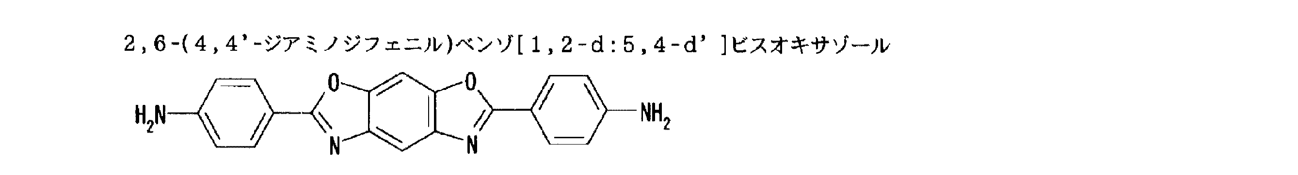
本発明で特に好ましく使用できるベンゾオキサゾール構造を有する芳香族ジアミン類と、芳香族テトラカルボン酸無水物類とを反応させて得られるポリイミドベンゾオキサゾールを主成分とするポリイミドベンゾオキサゾールに使用される、ベンゾオキサゾール構造を有する芳香族ジアミン類として、下記の化合物が例示できる。
As an example, the polyimide film of the present invention is obtained by a method generally called a casting film forming method using a polyamic acid obtained by reacting an aromatic diamine and an aromatic tetracarboxylic acid anhydride as a precursor. Can do.
The polyimide film in the present invention preferably has a benzoxazole structure.
Benzene used in polyimide benzoxazole mainly composed of polyimide benzoxazole obtained by reacting aromatic diamines having a benzoxazole structure and aromatic tetracarboxylic anhydrides that can be particularly preferably used in the present invention. Examples of aromatic diamines having an oxazole structure include the following compounds.
これらの中でも、合成のし易さの観点から、アミノ(アミノフェニル)ベンゾオキサゾールの各異性体が好ましい。ここで、「各異性体」とは、アミノ(アミノフェニル)ベンゾオキサゾールが有する2つアミノ基が配位位置に応じて定められる各異性体である(例;上記「化1」〜「化4」に記載の各化合物)。これらのジアミンは、単独で用いてもよいし、二種以上を併用してもよい。
本発明においては、前記ベンゾオキサゾール構造を有する芳香族ジアミンを70モル%以上使用することが好ましい。
Among these, amino (aminophenyl) benzoxazole isomers are preferable from the viewpoint of ease of synthesis. Here, “each isomer” refers to each isomer in which two amino groups of amino (aminophenyl) benzoxazole are determined according to the coordination position (eg, the above “formula 1” to “formula 4”). Each compound described in the above. These diamines may be used alone or in combination of two or more.
In the present invention, it is preferable to use 70 mol% or more of the aromatic diamine having the benzoxazole structure.
本発明は、前記事項に限定されず下記の芳香族ジアミンを使用してもよいが、好ましくは全芳香族ジアミンの30モル%未満であれば下記に例示されるベンゾオキサゾール構造を有しないジアミン類を一種又は二種以上、併用してのポリイミドフィルムである。
そのようなジアミン類としては、例えば、4,4’−ビス(3−アミノフェノキシ)ビフェニル、ビス[4−(3−アミノフェノキシ)フェニル]ケトン、ビス[4−(3−アミノフェノキシ)フェニル]スルフィド、ビス[4−(3−アミノフェノキシ)フェニル]スルホン、2,2−ビス[4−(3−アミノフェノキシ)フェニル]プロパン、2,2−ビス[4−(3−アミノフェノキシ)フェニル]−1,1,1,3,3,3−ヘキサフルオロプロパン、m−フェニレンジアミン、o−フェニレンジアミン、p−フェニレンジアミン、m−アミノベンジルアミン、p−アミノベンジルアミン、
The present invention is not limited to the above items, and the following aromatic diamines may be used. Preferably, the diamines do not have the benzoxazole structure exemplified below as long as the total aromatic diamine is less than 30 mol%. Is a polyimide film using one or two or more in combination.
Examples of such diamines include 4,4′-bis (3-aminophenoxy) biphenyl, bis [4- (3-aminophenoxy) phenyl] ketone, and bis [4- (3-aminophenoxy) phenyl]. Sulfide, bis [4- (3-aminophenoxy) phenyl] sulfone, 2,2-bis [4- (3-aminophenoxy) phenyl] propane, 2,2-bis [4- (3-aminophenoxy) phenyl] -1,1,1,3,3,3-hexafluoropropane, m-phenylenediamine, o-phenylenediamine, p-phenylenediamine, m-aminobenzylamine, p-aminobenzylamine,
3,3’−ジアミノジフェニルエーテル、3,4’−ジアミノジフェニルエーテル、4,4’−ジアミノジフェニルエーテル、3,3’−ジアミノジフェニルスルフィド、3,3’−ジアミノジフェニルスルホキシド、3,4’−ジアミノジフェニルスルホキシド、4,4’−ジアミノジフェニルスルホキシド、3,3’−ジアミノジフェニルスルホン、3,4’−ジアミノジフェニルスルホン、4,4’−ジアミノジフェニルスルホン、3,3’−ジアミノベンゾフェノン、3,4’−ジアミノベンゾフェノン、4,4’−ジアミノベンゾフェノン、3,3’−ジアミノジフェニルメタン、3,4’−ジアミノジフェニルメタン、4,4’−ジアミノジフェニルメタン、ビス[4−(4−アミノフェノキシ)フェニル]メタン、1,1−ビス[4−(4−アミノフェノキシ)フェニル]エタン、1,2−ビス[4−(4−アミノフェノキシ)フェニル]エタン、1,1−ビス[4−(4−アミノフェノキシ)フェニル]プロパン、1,2−ビス[4−(4−アミノフェノキシ)フェニル]プロパン、1,3−ビス[4−(4−アミノフェノキシ)フェニル]プロパン、2,2−ビス[4−(4−アミノフェノキシ)フェニル]プロパン、 3,3′-diaminodiphenyl ether, 3,4′-diaminodiphenyl ether, 4,4′-diaminodiphenyl ether, 3,3′-diaminodiphenyl sulfide, 3,3′-diaminodiphenyl sulfoxide, 3,4′-diaminodiphenyl sulfoxide 4,4′-diaminodiphenyl sulfoxide, 3,3′-diaminodiphenyl sulfone, 3,4′-diaminodiphenyl sulfone, 4,4′-diaminodiphenyl sulfone, 3,3′-diaminobenzophenone, 3,4′- Diaminobenzophenone, 4,4′-diaminobenzophenone, 3,3′-diaminodiphenylmethane, 3,4′-diaminodiphenylmethane, 4,4′-diaminodiphenylmethane, bis [4- (4-aminophenoxy) phenyl] methane, 1 , 1-Bi [4- (4-aminophenoxy) phenyl] ethane, 1,2-bis [4- (4-aminophenoxy) phenyl] ethane, 1,1-bis [4- (4-aminophenoxy) phenyl] propane, 1 , 2-bis [4- (4-aminophenoxy) phenyl] propane, 1,3-bis [4- (4-aminophenoxy) phenyl] propane, 2,2-bis [4- (4-aminophenoxy) phenyl ]propane,
1,1−ビス[4−(4−アミノフェノキシ)フェニル]ブタン、1,3−ビス[4−(4−アミノフェノキシ)フェニル]ブタン、1,4−ビス[4−(4−アミノフェノキシ)フェニル]ブタン、2,2−ビス[4−(4−アミノフェノシ)フェニル]ブタン、2,3−ビス[4−(4−アミノフェノキシ)フェニル]ブタン、2−[4−(4−アミノフェノキシ)フェニル]−2−[4−(4−アミノフェノキシ)−3−メチルフェニル]プロパン、2,2−ビス[4−(4−アミノフェノキシ)−3−メチルフェニル]プロパン、2−[4−(4−アミノフェノキシ)フェニル]−2−[4−(4−アミノフェノキシ)−3,5−ジメチルフェニル]プロパン、2,2−ビス[4−(4−アミノフェノキシ)−3,5−ジメチルフェニル]プロパン、2,2−ビス[4−(4−アミノフェノキシ)フェニル]−1,1,1,3,3,3−ヘキサフルオロプロパン、 1,1-bis [4- (4-aminophenoxy) phenyl] butane, 1,3-bis [4- (4-aminophenoxy) phenyl] butane, 1,4-bis [4- (4-aminophenoxy) Phenyl] butane, 2,2-bis [4- (4-aminophenoxy) phenyl] butane, 2,3-bis [4- (4-aminophenoxy) phenyl] butane, 2- [4- (4-aminophenoxy) Phenyl] -2- [4- (4-aminophenoxy) -3-methylphenyl] propane, 2,2-bis [4- (4-aminophenoxy) -3-methylphenyl] propane, 2- [4- ( 4-aminophenoxy) phenyl] -2- [4- (4-aminophenoxy) -3,5-dimethylphenyl] propane, 2,2-bis [4- (4-aminophenoxy) -3,5-dimethylphen Le] propane, 2,2-bis [4- (4-aminophenoxy) phenyl] -1,1,1,3,3,3-hexafluoropropane,
1,4−ビス(3−アミノフェノキシ)ベンゼン、1,3−ビス(3−アミノフェノキシ)ベンゼン、1,4−ビス(4−アミノフェノキシ)ベンゼン、4,4’−ビス(4−アミノフェノキシ)ビフェニル、ビス[4−(4−アミノフェノキシ)フェニル]ケトン、ビス[4−(4−アミノフェノキシ)フェニル]スルフィド、ビス[4−(4−アミノフェノキシ)フェニル]スルホキシド、ビス[4−(4−アミノフェノキシ)フェニル]スルホン、ビス[4−(3−アミノフェノキシ)フェニル]エーテル、ビス[4−(4−アミノフェノキシ)フェニル]エーテル、1,3−ビス[4−(4−アミノフェノキシ)ベンゾイル]ベンゼン、1,3−ビス[4−(3−アミノフェノキシ)ベンゾイル]ベンゼン、1,4−ビス[4−(3−アミノフェノキシ)ベンゾイル]ベンゼン、4,4’−ビス[(3−アミノフェノキシ)ベンゾイル]ベンゼン、1,1−ビス[4−(3−アミノフェノキシ)フェニル]プロパン、1,3−ビス[4−(3−アミノフェノキシ)フェニル]プロパン、3,4’−ジアミノジフェニルスルフィド、 1,4-bis (3-aminophenoxy) benzene, 1,3-bis (3-aminophenoxy) benzene, 1,4-bis (4-aminophenoxy) benzene, 4,4′-bis (4-aminophenoxy) ) Biphenyl, bis [4- (4-aminophenoxy) phenyl] ketone, bis [4- (4-aminophenoxy) phenyl] sulfide, bis [4- (4-aminophenoxy) phenyl] sulfoxide, bis [4- ( 4-aminophenoxy) phenyl] sulfone, bis [4- (3-aminophenoxy) phenyl] ether, bis [4- (4-aminophenoxy) phenyl] ether, 1,3-bis [4- (4-aminophenoxy) ) Benzoyl] benzene, 1,3-bis [4- (3-aminophenoxy) benzoyl] benzene, 1,4-bis [4- (3 Aminophenoxy) benzoyl] benzene, 4,4′-bis [(3-aminophenoxy) benzoyl] benzene, 1,1-bis [4- (3-aminophenoxy) phenyl] propane, 1,3-bis [4- (3-aminophenoxy) phenyl] propane, 3,4'-diaminodiphenyl sulfide,
2,2−ビス[3−(3−アミノフェノキシ)フェニル]−1,1,1,3,3,3−ヘキサフルオロプロパン、ビス[4−(3−アミノフェノキシ)フェニル]メタン、1,1−ビス[4−(3−アミノフェノキシ)フェニル]エタン、1,2−ビス[4−(3−アミノフェノキシ)フェニル]エタン、ビス[4−(3−アミノフェノキシ)フェニル]スルホキシド、4,4’−ビス[3−(4−アミノフェノキシ)ベンゾイル]ジフェニルエーテル、4,4’−ビス[3−(3−アミノフェノキシ)ベンゾイル]ジフェニルエーテル、4,4’−ビス[4−(4−アミノ−α,α−ジメチルベンジル)フェノキシ]ベンゾフェノン、4,4’−ビス[4−(4−アミノ−α,α−ジメチルベンジル)フェノキシ]ジフェニルスルホン、ビス[4−{4−(4−アミノフェノキシ)フェノキシ}フェニル]スルホン、1,4−ビス[4−(4−アミノフェノキシ)フェノキシ−α,α−ジメチルベンジル]ベンゼン、1,3−ビス[4−(4−アミノフェノキシ)フェノキシ−α,α−ジメチルベンジル]ベンゼン、1,3−ビス[4−(4−アミノ−6−トリフルオロメチルフェノキシ)−α,α−ジメチルベンジル]ベンゼン、1,3−ビス[4−(4−アミノ−6−フルオロフェノキシ)−α,α−ジメチルベンジル]ベンゼン、1,3−ビス[4−(4−アミノ−6−メチルフェノキシ)−α,α−ジメチルベンジル]ベンゼン、1,3−ビス[4−(4−アミノ−6−シアノフェノキシ)−α,α−ジメチルベンジル]ベンゼン、 2,2-bis [3- (3-aminophenoxy) phenyl] -1,1,1,3,3,3-hexafluoropropane, bis [4- (3-aminophenoxy) phenyl] methane, 1,1 -Bis [4- (3-aminophenoxy) phenyl] ethane, 1,2-bis [4- (3-aminophenoxy) phenyl] ethane, bis [4- (3-aminophenoxy) phenyl] sulfoxide, 4,4 '-Bis [3- (4-aminophenoxy) benzoyl] diphenyl ether, 4,4'-bis [3- (3-aminophenoxy) benzoyl] diphenyl ether, 4,4'-bis [4- (4-amino-α) , Α-dimethylbenzyl) phenoxy] benzophenone, 4,4′-bis [4- (4-amino-α, α-dimethylbenzyl) phenoxy] diphenylsulfone, bis 4- {4- (4-aminophenoxy) phenoxy} phenyl] sulfone, 1,4-bis [4- (4-aminophenoxy) phenoxy-α, α-dimethylbenzyl] benzene, 1,3-bis [4- (4-aminophenoxy) phenoxy-α, α-dimethylbenzyl] benzene, 1,3-bis [4- (4-amino-6-trifluoromethylphenoxy) -α, α-dimethylbenzyl] benzene, 1,3 -Bis [4- (4-amino-6-fluorophenoxy) -α, α-dimethylbenzyl] benzene, 1,3-bis [4- (4-amino-6-methylphenoxy) -α, α-dimethylbenzyl Benzene, 1,3-bis [4- (4-amino-6-cyanophenoxy) -α, α-dimethylbenzyl] benzene,
3,3’−ジアミノ−4,4’−ジフェノキシベンゾフェノン、4,4’−ジアミノ−5,5’−ジフェノキシベンゾフェノン、3,4’−ジアミノ−4,5’−ジフェノキシベンゾフェノン、3,3’−ジアミノ−4−フェノキシベンゾフェノン、4,4’−ジアミノ−5−フェノキシベンゾフェノン、3,4’−ジアミノ−4−フェノキシベンゾフェノン、3,4’−ジアミノ−5’−フェノキシベンゾフェノン、3,3’−ジアミノ−4,4’−ジビフェノキシベンゾフェノン、4,4’−ジアミノ−5,5’−ジビフェノキシベンゾフェノン、3,4’−ジアミノ−4,5’−ジビフェノキシベンゾフェノン、3,3’−ジアミノ−4−ビフェノキシベンゾフェノン、4,4’−ジアミノ−5−ビフェノキシベンゾフェノン、3,4’−ジアミノ−4−ビフェノキシベンゾフェノン、3,4’−ジアミノ−5’−ビフェノキシベンゾフェノン、1,3−ビス(3−アミノ−4−フェノキシベンゾイル)ベンゼン、1,4−ビス(3−アミノ−4−フェノキシベンゾイル)ベンゼン、1,3−ビス(4−アミノ−5−フェノキシベンゾイル)ベンゼン、1,4−ビス(4−アミノ−5−フェノキシベンゾイル)ベンゼン、1,3−ビス(3−アミノ−4−ビフェノキシベンゾイル)ベンゼン、1,4−ビス(3−アミノ−4−ビフェノキシベンゾイル)ベンゼン、1,3−ビス(4−アミノ−5−ビフェノキシベンゾイル)ベンゼン、1,4−ビス(4−アミノ−5−ビフェノキシベンゾイル)ベンゼン、2,6−ビス[4−(4−アミノ−α,α−ジメチルベンジル)フェノキシ]ベンゾニトリル及び上記芳香族ジアミンにおける芳香環上の水素原子の一部もしくは全てがハロゲン原子、炭素数1〜3のアルキル基又はアルコキシル基、シアノ基、又はアルキル基又はアルコキシル基の水素原子の一部もしくは全部がハロゲン原子で置換された炭素数1〜3のハロゲン化アルキル基又はアルコキシル基で置換された芳香族ジアミン等が挙げられる。 3,3′-diamino-4,4′-diphenoxybenzophenone, 4,4′-diamino-5,5′-diphenoxybenzophenone, 3,4′-diamino-4,5′-diphenoxybenzophenone, 3, 3'-diamino-4-phenoxybenzophenone, 4,4'-diamino-5-phenoxybenzophenone, 3,4'-diamino-4-phenoxybenzophenone, 3,4'-diamino-5'-phenoxybenzophenone, 3,3 '-Diamino-4,4'-dibiphenoxybenzophenone, 4,4'-diamino-5,5'-dibiphenoxybenzophenone, 3,4'-diamino-4,5'-dibiphenoxybenzophenone, 3,3'- Diamino-4-biphenoxybenzophenone, 4,4′-diamino-5-biphenoxybenzophenone, 3,4 -Diamino-4-biphenoxybenzophenone, 3,4'-diamino-5'-biphenoxybenzophenone, 1,3-bis (3-amino-4-phenoxybenzoyl) benzene, 1,4-bis (3-amino- 4-phenoxybenzoyl) benzene, 1,3-bis (4-amino-5-phenoxybenzoyl) benzene, 1,4-bis (4-amino-5-phenoxybenzoyl) benzene, 1,3-bis (3-amino) -4-biphenoxybenzoyl) benzene, 1,4-bis (3-amino-4-biphenoxybenzoyl) benzene, 1,3-bis (4-amino-5-biphenoxybenzoyl) benzene, 1,4-bis (4-Amino-5-biphenoxybenzoyl) benzene, 2,6-bis [4- (4-amino-α, α-dimethylbenzyl) pheno Si] A part or all of the hydrogen atoms on the aromatic ring in the benzonitrile and the aromatic diamine are halogen atoms, alkyl groups having 1 to 3 carbon atoms or alkoxyl groups, cyano groups, or alkyl groups or alkoxyl group hydrogen atoms. Examples thereof include aromatic diamines substituted with a halogenated alkyl group having 1 to 3 carbon atoms, partially or entirely substituted with halogen atoms, or alkoxyl groups.
本発明で用いられる芳香族テトラカルボン酸類は例えば芳香族テトラカルボン酸無水物類である。芳香族テトラカルボン酸無水物類としては、具体的には、以下のものが挙げられる。 The aromatic tetracarboxylic acids used in the present invention are, for example, aromatic tetracarboxylic anhydrides. Specific examples of the aromatic tetracarboxylic acid anhydrides include the following.
これらのテトラカルボン酸二無水物は単独で用いてもよいし、二種以上を併用してもよい。
本発明においては、全テトラカルボン酸二無水物の30モル%未満であれば下記に例示される非芳香族のテトラカルボン酸二無水物類を一種又は二種以上、併用しても構わない。そのようなテトラカルボン酸無水物としては、例えば、ブタン−1,2,3,4−テトラカルボン酸二無水物、ペンタン−1,2,4,5−テトラカルボン酸二無水物、シクロブタンテトラカルボン酸二無水物、シクロペンタン−1,2,3,4−テトラカルボン酸二無水物、シクロヘキサン−1,2,4,5−テトラカルボン酸二無水物、シクロヘキサ−1−エン−2,3,5,6−テトラカルボン酸二無水物、3−エチルシクロヘキサ−1−エン−3−(1,2),5,6−テトラカルボン酸二無水物、1−メチル−3−エチルシクロヘキサン−3−(1,2),5,6−テトラカルボン酸二無水物、1−メチル−3−エチルシクロヘキサ−1−エン−3−(1,2),5,6−テトラカルボン酸二無水物、1−エチルシクロヘキサン−1−(1,2),3,4−テトラカルボン酸二無水物、1−プロピルシクロヘキサン−1−(2,3),3,4−テトラカルボン酸二無水物、1,3−ジプロピルシクロヘキサン−1−(2,3),3−(2,3)−テトラカルボン酸二無水物、ジシクロヘキシル−3,4,3’,4’−テトラカルボン酸二無水物、
These tetracarboxylic dianhydrides may be used alone or in combination of two or more.
In the present invention, one or two or more non-aromatic tetracarboxylic dianhydrides exemplified below may be used in combination as long as they are less than 30 mol% of the total tetracarboxylic dianhydrides. Examples of such tetracarboxylic acid anhydrides include butane-1,2,3,4-tetracarboxylic dianhydride, pentane-1,2,4,5-tetracarboxylic dianhydride, and cyclobutanetetracarboxylic acid. Acid dianhydride, cyclopentane-1,2,3,4-tetracarboxylic dianhydride, cyclohexane-1,2,4,5-tetracarboxylic dianhydride, cyclohex-1-ene-2,3 5,6-tetracarboxylic dianhydride, 3-ethylcyclohex-1-ene-3- (1,2), 5,6-tetracarboxylic dianhydride, 1-methyl-3-ethylcyclohexane-3 -(1,2), 5,6-tetracarboxylic dianhydride, 1-methyl-3-ethylcyclohex-1-ene-3- (1,2), 5,6-tetracarboxylic dianhydride 1-ethylcyclohexane -(1,2), 3,4-tetracarboxylic dianhydride, 1-propylcyclohexane-1- (2,3), 3,4-tetracarboxylic dianhydride, 1,3-dipropylcyclohexane- 1- (2,3), 3- (2,3) -tetracarboxylic dianhydride, dicyclohexyl-3,4,3 ′, 4′-tetracarboxylic dianhydride,
ビシクロ[2.2.1]ヘプタン−2,3,5,6−テトラカルボン酸二無水物、1−プロピルシクロヘキサン−1−(2,3),3,4−テトラカルボン酸二無水物、1,3−ジプロピルシクロヘキサン−1−(2,3),3−(2,3)−テトラカルボン酸二無水物、ジシクロヘキシル−3,4,3’,4’−テトラカルボン酸二無水物、ビシクロ[2.2.1]ヘプタン−2,3,5,6−テトラカルボン酸二無水物、ビシクロ[2.2.2]オクタン−2,3,5,6−テトラカルボン酸二無水物、ビシクロ[2.2.2]オクト−7−エン−2,3,5,6−テトラカルボン酸二無水物等が挙げられる。これらのテトラカルボン酸二無水物は単独で用いてもよいし、二種以上を併用してもよい。 Bicyclo [2.2.1] heptane-2,3,5,6-tetracarboxylic dianhydride, 1-propylcyclohexane-1- (2,3), 3,4-tetracarboxylic dianhydride, 1 , 3-Dipropylcyclohexane-1- (2,3), 3- (2,3) -tetracarboxylic dianhydride, dicyclohexyl-3,4,3 ′, 4′-tetracarboxylic dianhydride, bicyclo [2.2.1] Heptane-2,3,5,6-tetracarboxylic dianhydride, bicyclo [2.2.2] octane-2,3,5,6-tetracarboxylic dianhydride, bicyclo [2.2.2] Oct-7-ene-2,3,5,6-tetracarboxylic dianhydride and the like. These tetracarboxylic dianhydrides may be used alone or in combination of two or more.
前記芳香族ジアミン類と、芳香族テトラカルボン酸(無水物)類とを反応(重合)させてポリアミド酸を得るときに用いる溶媒は、原料となるモノマー及び生成するポリアミド酸のいずれをも溶解するものであれば特に限定されないが、極性有機溶媒が好ましく、例えば、N−メチル−2−ピロリドン、N−アセチル−2−ピロリドン、N,N−ジメチルホルムアミド、N,N−ジエチルホルムアミド、N,N−ジメチルアセトアミド、ジメチルスルホキシド、ヘキサメチルホスホリックアミド、エチルセロソルブアセテート、ジエチレングリコールジメチルエーテル、スルホラン、ハロゲン化フェノール類等があげられる。 これらの溶媒は、単独あるいは混合して使用することができる。溶媒の使用量は、原料となるモノマーを溶解するのに十分な量であればよく、具体的な使用量としては、モノマーを溶解した溶液に占めるモノマーの質量が、通常5〜40質量%、好ましくは10〜30質量%となるような量が挙げられる。 The solvent used when the polyamic acid is obtained by reacting (polymerizing) the aromatic diamine and the aromatic tetracarboxylic acid (anhydride) dissolves both the monomer as a raw material and the polyamic acid to be produced. Although it will not specifically limit if it is a thing, A polar organic solvent is preferable, for example, N-methyl- 2-pyrrolidone, N-acetyl- 2-pyrrolidone, N, N- dimethylformamide, N, N- diethylformamide, N, N -Dimethylacetamide, dimethyl sulfoxide, hexamethylphosphoric amide, ethyl cellosolve acetate, diethylene glycol dimethyl ether, sulfolane, halogenated phenols and the like. These solvents can be used alone or in combination. The amount of the solvent used may be an amount sufficient to dissolve the monomer as a raw material. As a specific amount used, the mass of the monomer in the solution in which the monomer is dissolved is usually 5 to 40% by mass, The amount is preferably 10 to 30% by mass.
ポリアミド酸を得るための重合反応の条件は従来公知の条件を適用すればよく、具体例として、有機溶媒中、0〜80℃の温度範囲で、10分〜30時間連続して撹拌及び/又は混合することが挙げられる。必要により重合反応を分割したり、温度を上下させてもかまわない。この場合に、両モノマーの添加順序には特に制限はないが、芳香族ジアミン類の溶液中に芳香族テトラカルボン酸無水物類を添加するのが好ましい。重合反応によって得られるポリアミド酸溶液に占めるポリアミド酸の質量は、好ましくは5〜40質量%、より好ましくは10〜30質量%であり、前記溶液の粘度はブルックフィールド粘度計による測定(25℃)で、送液の安定性の点から、好ましくは10〜2000Pa・sであり、より好ましくは100〜1000Pa・sである。本発明におけるポリアミド酸の還元粘度(ηsp/C)は、特に限定するものではないが3.0dl/g以上が好ましく、4.0dl/g以上がさらに好ましい。
重合反応中に真空脱泡することは、良質なポリアミド酸の有機溶媒溶液を製造するのに有効である。また、重合反応の前に芳香族ジアミン類に少量の末端封止剤を添加して重合を制御することを行ってもよい。末端封止剤としては、無水マレイン酸等といった炭素−炭素二重結合を有する化合物が挙げられる。無水マレイン酸を使用する場合の使用量は、芳香族ジアミン類1モル当たり好ましくは0.001〜1.0モルである。
The polymerization reaction conditions for obtaining the polyamic acid may be conventionally known conditions. As a specific example, stirring and / or continuous in an organic solvent at a temperature range of 0 to 80 ° C. for 10 minutes to 30 hours. Mixing may be mentioned. If necessary, the polymerization reaction may be divided or the temperature may be increased or decreased. In this case, the order of adding both monomers is not particularly limited, but it is preferable to add aromatic tetracarboxylic acid anhydrides to the solution of aromatic diamines. The mass of the polyamic acid in the polyamic acid solution obtained by the polymerization reaction is preferably 5 to 40% by mass, more preferably 10 to 30% by mass, and the viscosity of the solution is measured with a Brookfield viscometer (25 ° C.). From the viewpoint of the stability of liquid feeding, it is preferably 10 to 2000 Pa · s, and more preferably 100 to 1000 Pa · s. The reduced viscosity (ηsp / C) of the polyamic acid in the present invention is not particularly limited, but is preferably 3.0 dl / g or more, and more preferably 4.0 dl / g or more.
Vacuum defoaming during the polymerization reaction is effective for producing a high-quality polyamic acid organic solvent solution. Moreover, you may perform superposition | polymerization by adding a small amount of terminal blockers to aromatic diamines before a polymerization reaction. Examples of the end capping agent include compounds having a carbon-carbon double bond such as maleic anhydride. The amount of maleic anhydride used is preferably 0.001 to 1.0 mol per mol of aromatic diamine.
本発明のポリイミドフィルムは、前述のジアミン類とテトラカルボン酸無水物類を溶液中で溶液重合して得られるポリアミド酸溶液を支持体上に塗布・乾燥させることで自己支持性を有するポリイミド前駆体フィルムを形成した後、化学的方法ないしは加熱などによってイミド化反応させることで得られるものである。 The polyimide film of the present invention is a polyimide precursor having a self-supporting property by applying a polyamic acid solution obtained by solution polymerization of the above-mentioned diamines and tetracarboxylic acid anhydrides in a solution and drying on the support. After the film is formed, it is obtained by an imidization reaction by a chemical method or heating.
ポリイミドフィルムの前駆体であるグリーンフィルムの乾燥条件と高温イミド化の条件を選定して実施することが好ましい方法であり、グリーンフィルムを得るための乾燥条件としては、例えば、N,N−ジメチルアセトアミドを溶媒として用いる場合は、乾燥温度は、好ましくは70〜130℃、より好ましくは80〜125℃であり、さらに好ましくは85〜120℃である。この乾燥温度が130℃より高い場合は、分子量低下がおこり、グリーンフィルムが脆くなりやすい。また、グリーンフィルム製造時にイミド化が一部進行し、イミド化工程時に所望の物性が得られにくくなる。また70℃より低い場合は、乾燥時間が長くなり、分子量低下がおこりやすく、また乾燥不十分でハンドリング性が悪くなる傾向がある。また、乾燥時間としては乾燥温度にもよるが、好ましくは5〜90分間であり、より好ましくは15〜80分間である。乾燥時間が90分間より長い場合は、分子量低下がおこり、フィルムが脆くなりやすく、また5分間より短い場合は、乾燥不十分でハンドリング性が悪くなる傾向がある。
乾燥装置は従来公知のものを適用でき、熱風、熱窒素、遠赤外線、高周波誘導加熱などを挙げることができる。
It is preferable to select and carry out the drying conditions and high-temperature imidation conditions for the green film that is the precursor of the polyimide film. Examples of the drying conditions for obtaining the green film include N, N-dimethylacetamide. When using as a solvent, a drying temperature becomes like this. Preferably it is 70-130 degreeC, More preferably, it is 80-125 degreeC, More preferably, it is 85-120 degreeC. When this drying temperature is higher than 130 ° C., the molecular weight is lowered, and the green film tends to be brittle. In addition, imidization partially proceeds during the production of the green film, and it becomes difficult to obtain desired physical properties during the imidization process. On the other hand, when the temperature is lower than 70 ° C., the drying time becomes long, the molecular weight tends to decrease, and the handling property tends to be poor due to insufficient drying. Further, the drying time is preferably 5 to 90 minutes, more preferably 15 to 80 minutes, although it depends on the drying temperature. When the drying time is longer than 90 minutes, the molecular weight is lowered and the film tends to be fragile. When the drying time is shorter than 5 minutes, the handling property tends to be poor due to insufficient drying.
A conventionally known drying apparatus can be applied, and examples thereof include hot air, hot nitrogen, far infrared rays, and high frequency induction heating.
本発明のポリイミドフィルムは、c軸方向の結晶サイズが2nm以上30nm以下、好ましくは5nm以上20nm以下、さらに好ましくは8nm以上15nm以下であり、かつc軸方向の結晶乱れが1%以上15%以下、好ましくは1.5%以上10%以下、さらに好ましくは2%以上5%以下であることが特徴である。以下、かかる特徴を有するポリイミドフィルムの製法について詳解する。本発明のポリイミドフィルムは、グリーンフィルムを熱イミド化処理する過程において、特にイミド化反応が進行する過程において、適切な引張り応力下でc軸方向への結晶成長を生じさせることにより所定のc軸方向の結晶サイズとc軸方向の結晶乱れを実現することができる。具体的には、後述する途中構造の測定方法におけるc軸の結晶成長開始温度と、90%のイミド化率となるイミド化反応温度を求め、これら温度範囲で互いに直行する2方向に各1.01から1.2倍の引張り変形をフィルムに与えることにより実現できる。一例として、(I)(II)のプロセスを示すことができる。化学的方法においては、グリーンフィルムにイミド化剤を作用させ、後述する評価方法でc軸の結晶成長開始時間と、イミド化率が90%以上となる反応時間を求め、これら時間範囲で互いに直行する2方向に各1.01から1.2倍の引張り変形をフィルムに与えることにより実現できる。 The polyimide film of the present invention has a crystal size in the c-axis direction of 2 nm to 30 nm, preferably 5 nm to 20 nm, more preferably 8 nm to 15 nm, and crystal disorder in the c-axis direction is 1% to 15%. , Preferably 1.5% to 10%, more preferably 2% to 5%. Hereinafter, a method for producing a polyimide film having such characteristics will be described in detail. The polyimide film of the present invention has a predetermined c-axis by causing crystal growth in the c-axis direction under an appropriate tensile stress in the process of thermal imidization treatment of a green film, particularly in the process of imidization reaction. Crystal size in the direction and crystal disorder in the c-axis direction can be realized. Specifically, a c-axis crystal growth start temperature and an imidization reaction temperature at which an imidization rate of 90% in a method for measuring an intermediate structure described later are obtained, and 1. each of two directions orthogonal to each other in these temperature ranges. This can be realized by applying a tensile deformation of 01 to 1.2 times to the film. As an example, the processes (I) and (II) can be shown. In the chemical method, an imidizing agent is allowed to act on the green film, and the c-axis crystal growth start time and the reaction time at which the imidization rate is 90% or more are obtained by an evaluation method described later. It can be realized by giving the film a tensile deformation of 1.01 to 1.2 times in each of the two directions.
〔プロセスI〕(1)グリーンフィルムを25℃から50℃の温度域において、フィルム長手方向に1.01から1.2倍引張り変形させる。(2)引張り変形させたグリーンフィルムの両端をクリップないしピンテンターなどで把持する。(3)50℃から150℃の温度域では、フィルムの緩和、収縮に応じ、たるみを生じない程度にフィルム幅を調整する。(4)150℃から280℃の温度域では、フィルム幅方向に1.01から1.25倍引張り変形させる。(5)280℃から520℃の温度域では、0.99から1.02倍の範囲でフィルムがたるまない程度に把持を続ける。(6)室温まで冷却する。 [Process I] (1) A green film is tensilely deformed 1.01 to 1.2 times in the longitudinal direction of the film in a temperature range of 25 ° C. to 50 ° C. (2) Grip both ends of the green film that has been pulled and deformed with clips or pin tenters. (3) In the temperature range from 50 ° C. to 150 ° C., the film width is adjusted to such an extent that no sag is generated according to the relaxation and shrinkage of the film. (4) In the temperature range from 150 ° C. to 280 ° C., the film is subjected to tensile deformation in the film width direction by 1.01 to 1.25 times. (5) In the temperature range of 280 ° C. to 520 ° C., the grip is continued to such an extent that the film does not sag in the range of 0.99 to 1.02. (6) Cool to room temperature.
〔プロセスII〕(1)グリーンフィルムの両端をクリップないしピンテンターなどで把持する。(2)50℃から150℃の温度域では、フィルムの緩和、収縮に応じ、たるみを生じない程度にフィルム幅を調整する。(3)150℃から280℃の温度域では、互いに直行する2方向に1.01から1.25倍引張り変形させる。(4)280℃から520℃の温度域では、0.99から1.02倍の範囲でフィルムがたるまない程度に把持を続ける。(5)室温まで冷却する。
ポリイミドフィルムの厚さは特に限定されないが、通常1〜250μm、好ましくは2〜50μmである。またさらに高度な繰り返し曲げ、繰り返しひねりへの耐久性を求められる場合には2〜40μmが好ましく、2〜27μmがさらに好ましく、2〜15μmがなお好ましく、なおさらに2〜9μmが好ましい。この厚さはポリアミド酸溶液を支持体に塗布する際の塗布量や、ポリアミド酸溶液の濃度によって容易に制御し得る。
[Process II] (1) Grip both ends of the green film with clips or pin tenters. (2) In the temperature range from 50 ° C. to 150 ° C., the film width is adjusted to such an extent that no sagging occurs according to the relaxation and shrinkage of the film. (3) In the temperature range of 150 ° C. to 280 ° C., the tensile deformation is performed 1.01 to 1.25 times in two directions perpendicular to each other. (4) In the temperature range of 280 ° C. to 520 ° C., gripping is continued to such an extent that the film does not sag in the range of 0.99 to 1.02. (5) Cool to room temperature.
Although the thickness of a polyimide film is not specifically limited, Usually, it is 1-250 micrometers, Preferably it is 2-50 micrometers. Furthermore, when higher durability against repeated bending and repeated twisting is required, it is preferably 2 to 40 μm, more preferably 2 to 27 μm, still more preferably 2 to 15 μm, still more preferably 2 to 9 μm. This thickness can be easily controlled by the amount of the polyamic acid solution applied to the support and the concentration of the polyamic acid solution.
〔フィルム製膜途中のフィルム構造の測定方法〕
温度を順次変化させて測定できるように設計した、4連続型加熱炉を用いて、温度を変化させた時のフィルムの途中構造をX線回折測定とIR測定により評価する。測定サンプルには、塗工・乾燥のみ行ったグリーンフィルムを用い、直径7mmの円状にサンプルを切り出す。その円状サンプルをサンプル棒の先端に備えたサンプルホルダー内にセットし、温度変化に伴う溶媒蒸発で生じるフィルム収縮が行いように円状サンプルを真上から把持する。そのサンプル棒を所定の位置にセットした。室温から500℃の温度範囲内で、連続した4つの加熱炉の処理温度に変化をつけて配置し、サンプル棒を固定したまま加熱炉を順次移動させることで、上記2つの測定を個別に行う。具体的には、それぞれの加熱工程でフィルムを3分ずつ保持したのち次の炉に送ることで、イミド化反応処理を行いながら時間分割X線回折測定ないしはIR測定を実施する。
[Measurement method of film structure during film formation]
Using a four-continuous heating furnace designed so that the temperature can be changed sequentially, the intermediate structure of the film when the temperature is changed is evaluated by X-ray diffraction measurement and IR measurement. As a measurement sample, a green film that has been coated and dried is used, and the sample is cut into a circle with a diameter of 7 mm. The circular sample is set in a sample holder provided at the tip of the sample rod, and the circular sample is gripped from directly above so that film shrinkage caused by solvent evaporation accompanying temperature change is performed. The sample bar was set in place. Within the temperature range from room temperature to 500 ° C., the processing temperature of the four consecutive heating furnaces is changed and arranged, and the heating furnace is sequentially moved while the sample rod is fixed, so that the above two measurements are performed individually. . Specifically, the film is held for 3 minutes in each heating step and then sent to the next furnace to perform time-resolved X-ray diffraction measurement or IR measurement while performing imidization reaction treatment.
〔c軸の結晶成長開始時温度の評価方法〕
c軸方向の結晶サイズはX線回折法を用いて測定する。X線ソースとしては高輝度のX線源を用い、X線源方向とフィルム面とのなす角が垂直となすように、測定フィルムをセットし、透過法にてX線回折測定を行う。X線回折測定条件を下記に示す。
[X線回折測定条件]
グリーンフィルム厚さ;IF38μm相当
X線照射時間 ;1秒
データ転送時間 ;5秒
X線回折図形は、たとえば、HAMAMATU PHOTONICS K.K.製CCDカメラ(X−Ray Image Intensifier(V5445P MOD)及びDual Mode Cooled CCD CAMERA(C4880))等を用いて記録する。記録された画像データはパソコンに転送して、赤道方向及び方位角方向のデータを切り出した後、(001)面のピークの半価幅から、みかけの結晶サイズ(D001)を、次式に示すSherrerの式[式1]を用いて算出する。
[Method of evaluating temperature at the start of c-axis crystal growth]
The crystal size in the c-axis direction is measured using an X-ray diffraction method. A high-brightness X-ray source is used as the X-ray source, and the measurement film is set so that the angle formed by the X-ray source direction and the film surface is vertical, and X-ray diffraction measurement is performed by the transmission method. The X-ray diffraction measurement conditions are shown below.
[X-ray diffraction measurement conditions]
Green film thickness: IF equivalent to 38 μm X-ray irradiation time; 1 second Data transfer time; 5 seconds The X-ray diffraction pattern is, for example, HAMATATU PHOTOTONICS K. et al. K. Recording is performed using a CCD camera (X-Ray Image Intensifier (V5445P MOD) and Dual Mode Cooled CCD CAMERA (C4880)). The recorded image data is transferred to a personal computer, and after the equatorial and azimuth data are cut out, the apparent crystal size (D 001 ) is calculated from the half-value width of the peak on the (001) plane as Calculation is performed using the following Sherler equation [Equation 1].
[式1] D001(Å)=0.9・λ/β・cosθ
λ ; X線波長 (0.7293Å)
β ; (001)面のピーク半価幅
θ ; ブラッグ角
[Formula 1] D 001 (Å) = 0.9 · λ / β · cos θ
λ: X-ray wavelength (0.7293mm)
β: Peak width at half peak of (001) plane
θ = Bragg angle
炉内の滞留時間に対してD001をプロットした時に観察される立ち上がり開始時間を求め、温度プロファイルから、その立ち上がり開始時間に相当する温度をc軸の結晶成長開始時温度とする。
なお、高強度のX線源としてはシンクロトロンが好ましい。X線源としては、1015photons/(s・mm2・(mrad)2・0.1%バンド幅)以上のX線輝度、さらに好ましくは1018photons/(s・mm2・(mrad)2・0.1%バンド幅)以上のX線輝度のX線源を用いることが好ましい。以下に示す本発明の実施例では、大型放射光施設SPring8をX線源とし、BL40B2ハッチを使用した。Bending Magnetを通して取り出したX線はモノクロメーター(シリコン結晶の(111)面)を通して単色化したのち、共焦点ミラーを用いてX線ビームの形を成型した。
The rise start time observed when D001 is plotted against the residence time in the furnace is obtained, and the temperature corresponding to the rise start time is determined from the temperature profile as the c axis crystal growth start temperature.
A synchrotron is preferable as the high-intensity X-ray source. As an X-ray source, an X-ray brightness of 10 15 photons / (s · mm 2 · (mrad) 2 · 0.1% bandwidth) or more, more preferably 10 18 photons / (s · mm 2 · (mrad) It is preferable to use an X-ray source having an X-ray luminance of 2 · 0.1% bandwidth. In the following embodiment of the present invention, the large synchrotron radiation facility SPring8 is used as an X-ray source, and a BL40B2 hatch is used. X-rays taken out through the bending magnet were monochromatized through a monochromator ((111) plane of silicon crystal), and then the shape of the X-ray beam was shaped using a confocal mirror.
〔90%のイミド化率となるイミド化反応温度の評価方法〕
IR装置の外部に反射鏡を介して赤外光を取り出し、検出器との間に前述の4連続型加熱炉をセッティングすることで、イミド化反応追跡を実施する。4連続型加熱炉の操作方法は、X線回折方法に準拠した。下記に、IR測定条件を示す。
[IR測定条件]
グリーンフィルム厚さ;IF10μm相当
使用装置名 ; FT−IR FTS−60A/896 BIO−RAD社製
分解能 ; 2cm−1
測定波数範囲 ; 650〜8000 cm−1
感度 ; 1
検出時間 ; 1.05 sec.
[Evaluation method of imidation reaction temperature for 90% imidization ratio]
Infrared light is taken out of the IR apparatus through a reflecting mirror, and the above-described four-continuous heating furnace is set between the detector and the imidization reaction tracking. The operation method of the 4-continuous heating furnace conformed to the X-ray diffraction method. The IR measurement conditions are shown below.
[IR measurement conditions]
Green film thickness: IF equivalent to 10 μm Device name used: FT-IR FTS-60A / 896 manufactured by BIO-RAD Resolution: 2 cm −1
Measurement wave number range: 650-8000 cm −1
Sensitivity; 1
Detection time: 1.05 sec.
下記の式(2)を用いて、各滞留時間でのイミド化相対値IMxを求め、滞留時間に対するイミド化相対値をプロットしたグラフを作成する。なお、λ1778は、イミド特定波長1778cm−1(付近)における吸光度であり、λ1478は、芳香族環特定波長1478cm−1付近における測定面の吸光度である。 Using the following formula (2), an imidation relative value IMx at each residence time is obtained, and a graph in which the imidation relative value with respect to the residence time is plotted is created. Note that λ 1778 is the absorbance at the imide specific wavelength 1778 cm −1 (near), and λ 1478 is the absorbance of the measurement surface near the aromatic ring specific wavelength 1478 cm −1 .
[式2] IMx = λ1778/λ1478 [Formula 2] IMx = λ 1778 / λ 1478
400℃以上の最終イミド化反応温度におけるイミド化相対値IMxをイミド化率100%とした時に、90%のイミド化率となるイミド化相対値を求め、その相対値、前記グラフ及び温度プロファイルから、90%のイミド化率となるイミド化反応温度を求めた。 When the imidation relative value IMx at the final imidation reaction temperature of 400 ° C. or higher is defined as an imidization rate of 100%, an imidization relative value that gives an imidization rate of 90% is obtained, and the relative value, the graph, and the temperature profile The imidation reaction temperature at which an imidization rate of 90% was obtained.
〔c軸方向の結晶サイズ、及びc軸方向の結晶乱れの評価方法〕
c軸方向の結晶サイズ及びc軸方向の結晶乱れはX線回折法を用いて測定する。回転対陰極の銅ターゲットから発生するX線をX線源として用い、X線源方向とフィルム面とのなす角が垂直となすように測定フィルムをセットし、検出器としてシンチレーションカウンターを用い、透過法にてX線回折プロファイルを測定する。X線回折測定条件を下記に示す。
[X線回折測定条件]
使用装置名 ; RINT2500 リガク社製
出力 ; 40kV、200mA
アタッチメント; 繊維試料台
スリットサイズ; コリメータ:1mm、縦制限スリット:2°、横制限スリット:1/2°
計数時間 ; 4秒
ステップ角度 ; 0.01°
ゴニオ半径 ; 185mm
[Method of evaluating crystal size in c-axis direction and crystal disorder in c-axis direction]
The crystal size in the c-axis direction and the crystal disorder in the c-axis direction are measured using an X-ray diffraction method. Using the X-rays generated from the copper target of the rotating anti-cathode as the X-ray source, set the measurement film so that the angle between the X-ray source direction and the film surface is perpendicular, and use the scintillation counter as the detector and transmit The X-ray diffraction profile is measured by the method. The X-ray diffraction measurement conditions are shown below.
[X-ray diffraction measurement conditions]
Device used: RINT2500 Rigaku Corporation output: 40 kV, 200 mA
Attachment; Fiber sample table Slit size; Collimator: 1 mm, Vertical restriction slit: 2 °, Horizontal restriction slit: 1/2 °
Counting time: 4 seconds Step angle: 0.01 °
Gonio radius; 185mm
得られたX線回折プロファイルから、(00L)面に相当する回折ピークの積分幅を評価する。この回折プロファイルの積分幅(δs)0から、真の結晶サイズ(D)と結晶の乱れgを、次式に示すホーゼマンの式[式3]を用いて算出する。 From the obtained X-ray diffraction profile, the integral width of the diffraction peak corresponding to the (00L) plane is evaluated. From the integral width (δs) 0 of this diffraction profile, the true crystal size (D) and the crystal disturbance g are calculated using the Hosmann equation [Equation 3] shown below.
[式3] (δs)0 2 =(1/D)2 + (πgm)4 / c2
ここでDは真の結晶サイズ、mは次数、cは結晶格子の間隔を示す。
[Formula 3] (δs) 0 2 = (1 / D) 2 + (πgm) 4 / c 2
Here, D is the true crystal size, m is the order, and c is the crystal lattice spacing.
ホーゼマンの理論を適用すると、これらの積分幅の2乗をそれぞれの回折次数の4乗に対してプロットすることで直線が得られ、この直線の傾き(以下、ホーゼマンプロットの傾きという)を求める。このホーゼマンプロットの傾きを用いて、下記の式に代入することで結晶格子間隔の乱れ度(g)を算出する。この式は、ホーゼマンプロットの傾き=(πg)4/c2で表わされる(上記の「高分子のX線回折」のP395を参照) When applying the Hozeman theory, a straight line is obtained by plotting the square of these integral widths against the fourth power of the respective diffraction orders, and the slope of this straight line (hereinafter referred to as the slope of the Hozeman plot) is obtained. . The degree of disorder (g) of the crystal lattice spacing is calculated by substituting into the following equation using the slope of this Hozeman plot. This equation is expressed by the slope of the Hozeman plot = (πg) 4 / c 2 (see P395 in “X-ray diffraction of polymer” above).
次に、上述したポリイミドベンゾオキサゾールフィルムを用いたプリント配線基板用ベース基板を説明する。
ここで、プリント配線基板用ベース基板とは、絶縁板としてのポリイミドフィルムの少なくとも片面に金属層を積層してなる構成の略平板状の基板である。積層される金属層は、エッチング等の加工によって回路を形成することが意図される回路用の金属層であってもよいし、特に後加工をせずに絶縁板と一緒になって放熱等の目的に用いられる金属層であってもよい。プリント配線基板用ベース基板の用途としては、FPC、TAB用キャリアテープ等が、高温環境下における膨れや剥がれが小さいという本発明のポリイミドフィルムの特徴を活かすことができるため好ましい。ポリイミドフィルムの少なくとも片面に積層される金属は特に限定はなく、好ましくは銅、アルミニウム、ステンレス鋼などである。
積層方法は特に問わず、接着剤を用いてポリイミドフィルムに金属板を貼り付ける方法、金属板を支持体として、そこにポリアミド酸溶液を塗布して上述のようにイミド化してフィルムを形成させる方法、ポリイミドフィルムに蒸着、スパッタリング、イオンプレーティングなどの乾式製膜法(真空コーティング技術)を用いて金属層を形成する方法、無電解めっき、電気めっきなどの湿式メッキ法により金属層をポリイミドフィルムに形成する方法などが挙げられる。
これらの方法を単独で、あるいは組み合わせることによってポリイミドフィルムの少なくとも片面に金属層を積層することができる。
本発明で使用する金属層の表面には、金属単体や金属酸化物などといった無機物の塗膜を形成してもよい。また金属層の表面を、カップリング剤(アミノシラン、エポキシシランなど)による処理、サンドプラスト処理、ホ−リング処理、コロナ処理、プラズマ処理、エッチング処理などに供してもよい。同様に、ポリイミドベンゾオキサゾールフィルムの表面をホ−ニング処理、コロナ処理、プラズマ処理、エッチング処理などに供してもよい。
Next, a printed wiring board base substrate using the above-described polyimide benzoxazole film will be described.
Here, the base substrate for a printed wiring board is a substantially flat substrate having a structure in which a metal layer is laminated on at least one surface of a polyimide film as an insulating plate. The metal layer to be laminated may be a metal layer for a circuit that is intended to form a circuit by processing such as etching or the like. It may be a metal layer used for the purpose. As the use of the base substrate for a printed wiring board, FPC, TAB carrier tape, and the like are preferable because the characteristics of the polyimide film of the present invention such that swelling and peeling under a high temperature environment are small can be utilized. The metal laminated on at least one surface of the polyimide film is not particularly limited, and preferably copper, aluminum, stainless steel, or the like.
The method of laminating is not particularly limited, and a method of attaching a metal plate to a polyimide film using an adhesive, a method of forming a film by applying a polyamic acid solution to the metal plate as a support and imidizing as described above A method of forming a metal layer on a polyimide film using a dry film forming method (vacuum coating technique) such as vapor deposition, sputtering, or ion plating, or a metal layer on a polyimide film by a wet plating method such as electroless plating or electroplating. The method of forming etc. are mentioned.
A metal layer can be laminated on at least one surface of the polyimide film by combining these methods alone or in combination.
An inorganic coating film such as a single metal or a metal oxide may be formed on the surface of the metal layer used in the present invention. Further, the surface of the metal layer may be subjected to treatment with a coupling agent (aminosilane, epoxysilane, etc.), sand plast treatment, hole treatment, corona treatment, plasma treatment, etching treatment, and the like. Similarly, the surface of the polyimide benzoxazole film may be subjected to honing treatment, corona treatment, plasma treatment, etching treatment, and the like.
〔ゲルボテスターを用いた繰り返しひねり屈曲試験〕
フレキシブルプリント配線板で一般に行われている屈曲特性の評価方法には、MIT法やIPC法が用いられてきたが、これら評価方法は一方向の屈曲特性の情報しか得られず、今回のような一方向以外にランダムな方向のひねり屈曲特性も評価するには不十分であった。そこで、本発明におけるポリイミドフィルムの耐ひねり屈曲試験には、ランダムな方向、場所での曲げに加えて「ひねり」も加わる、ゲルボテスター(理学工業(株)社製)を用いた評価方法を採用した。条件としては、MIL−B131Hで112inch×8inchの試料片を直径3(1/2)inchの円筒状とし、両端を保持し、初期把持間隔7inchとし、ストロークの3(1/2)inchで、400度のひねりを加えるものでこの動作の繰り返し往復運動を40回/minの速さで、23℃、相対湿度65%の条件下で10回行った。10回のゲルボ試験を行なったフィルムサンプルから100mm×100mmのサイズに切り出したものについて、濾紙上でインクの透過箇所の個数を数え、その個数をピンホール個数として用いた。このピンホール個数の少ないものが耐ゲルボ性の高い基材であり、本発明の基材として有効であることを示す。
[Repeated twist bending test using gel bot tester]
The MIT method and the IPC method have been used for the evaluation method of the bending characteristic generally performed in the flexible printed wiring board. However, these evaluation methods can only obtain information on the bending characteristic in one direction, It was not sufficient to evaluate twisting properties in random directions other than one direction. Therefore, an evaluation method using a gel bot tester (manufactured by Rigaku Kogyo Co., Ltd.) was employed in the twist resistance test of the polyimide film according to the present invention, in which “twist” was added in addition to bending in a random direction and place. . As conditions, a MIL-B131H sample piece of 112 inch × 8 inch is cylindrical with a diameter of 3 (1/2) inch, both ends are held, an initial gripping interval is 7 inch, and a stroke is 3 (1/2) inch. A reciprocating motion of this operation was performed 10 times at a speed of 40 times / min under the conditions of 23 ° C. and 65% relative humidity with a twist of 400 degrees. About what was cut out to the size of 100 mm x 100 mm from the film sample which performed the gelbo test 10 times, the number of the permeation | transmission locations of the ink was counted on the filter paper, and the number was used as the number of pinholes. A material having a small number of pinholes is a base material having high gelbo resistance, and is effective as a base material of the present invention.
以下、本発明の実施例を挙げて説明するが、本発明はこれらに限定されるものではない。なお、以下の実施例における物性の評価方法は前記したもの以外は、以下の通りである。 Examples of the present invention will be described below, but the present invention is not limited thereto. In addition, the evaluation method of the physical property in the following examples is as follows except for the above.
1.ポリアミド酸の還元粘度(ηsp/C)
ポリマー濃度が0.2g/dlとなるようにN−メチル−2−ピロリドンに溶解した溶液をウベローデ型の粘度管により30℃で測定した。
1. Reduced viscosity of polyamic acid (ηsp / C)
A solution dissolved in N-methyl-2-pyrrolidone so that the polymer concentration was 0.2 g / dl was measured at 30 ° C. using an Ubbelohde type viscosity tube.
2.ポリイミドフィルムのフィルム厚さ
フィルムの厚さは、マイクロメーター(ファインリューフ社製、ミリトロン1254D)を用いて測定した。
2. Film thickness of polyimide film The thickness of the film was measured using a micrometer (Finereuf, Millitron 1254D).
3.ポリイミドフィルムの引張弾性率、引張破断強度及び引張破断伸度
乾燥後のフィルムを長手方向(MD方向)及び幅方向(TD方向)にそれぞれ長さ100mm、幅10mmの短冊状に切り出して試験片とし、引張試験機(島津製作所製オートグラフ(商品名)機種名AG−5000A)を用い、引張速度50mm/分、チャック間距離40mmの条件で、引張弾性率、引張破断強度及び引張破断伸度を測定した。
3. Tensile modulus, tensile breaking strength and tensile breaking elongation of polyimide film The film after drying was cut into strips having a length of 100 mm and a width of 10 mm in the longitudinal direction (MD direction) and the width direction (TD direction), respectively, and used as test pieces. Using a tensile tester (Shimadzu Autograph (trade name) model name AG-5000A), the tensile modulus, tensile breaking strength and tensile breaking elongation were measured under the conditions of a tensile speed of 50 mm / min and a distance between chucks of 40 mm. It was measured.
4.ポリイミドフィルムの線膨張係数(CTE)
測定対象のポリイミドフィルムについて、下記条件でMD方向及びTD方向の寸法変化率をそれぞれ測定し、30℃〜45℃、45℃〜60℃、・・・と15℃の間隔での寸法変化率/温度を測定し、この測定を300℃まで行い、全測定値の平均値をCTEとして算出した。MD方向とTD方向の意味は上記「3.」の測定と同じである。
装置名 ; MACサイエンス社製TMA4000S
試料長さ ; 20mm
試料幅 ; 2mm
昇温開始温度 ; 25℃
昇温終了温度 ; 400℃
昇温速度 ; 5℃/min
雰囲気 ; アルゴン
4). Linear expansion coefficient (CTE) of polyimide film
For the polyimide film to be measured, the dimensional change rate in the MD direction and the TD direction is measured under the following conditions, respectively, and the dimensional change rate at intervals of 30 ° C. to 45 ° C., 45 ° C. to 60 ° C.,. The temperature was measured, this measurement was performed up to 300 ° C., and the average value of all measured values was calculated as CTE. The meanings of the MD direction and the TD direction are the same as in the measurement of “3.” above.
Device name: TMA4000S manufactured by MAC Science
Sample length; 20mm
Sample width: 2 mm
Temperature rise start temperature: 25 ° C
Temperature rising end temperature: 400 ° C
Temperature increase rate: 5 ° C / min
Atmosphere: Argon
5.ポリイミドフィルムの融点、ガラス転移温度
試料の熱的データ(融点(融解ピーク温度Tpm)とガラス転移点(Tmg))をJIS K 7121に準拠して下記測定条件で求めた。
装置名 ; MACサイエンス社製DSC3100S
パン ; アルミパン(非気密型)
試料質量 ; 4mg
昇温開始温度 ; 30℃
昇温速度 ; 20℃/min
雰囲気 ; アルゴン
5. Melting point and glass transition temperature of polyimide film Thermal data (melting point (melting peak temperature Tpm) and glass transition point (Tmg)) of the sample were determined under the following measurement conditions in accordance with JIS K7121.
Device name: DSC3100S manufactured by MAC Science
Pan : Aluminum pan (non-airtight)
Sample mass: 4mg
Temperature rising start temperature: 30 ° C
Temperature increase rate: 20 ° C / min
Atmosphere: Argon
(実施例1〜2)
<重合>
窒素導入管,温度計,攪拌棒を備えた反応容器内を窒素置換した後,5−アミノ−2−(p−アミノフェニル)ベンゾオキサゾール(p−DAMBO)300質量部を仕込んだ。次いで,N,N−ジメチルアセトアミド4400質量部を加えて完全に溶解させた後,ピロメリット酸二無水物300質量部を加え,25℃の反応温度で17時間攪拌すると,褐色で粘調なポリアミド酸溶液が得られた。このもののηsp/Cは4.1dl/gであった。
<ポリイミド前駆体フィルム(グリーンフィルム)の作製>
続いてこのポリアミド酸溶液をTダイを用いてステンレスベルトにコーティングし、表1に示す処理条件にて乾燥を行い、乾燥後に自己支持性となったポリアミド酸フィルムをステンレスベルトから剥離し厚さ70μmのグリーンフィルムを得た。このときのグリーンフィルムの残溶媒量は36%であった。
得られたグリーンフィルムを用いて、あらかじめ、c軸結晶成長開始温度、ならびに90%イミド化率到達温度を求めた。結果を表1に示す。求めたc軸結晶成長開始温度、ならびに90%イミド化率到達温度に基づき、以下の工程条件を決めた。
<縦延伸>
得られたグリーンフィルムを28℃の室温下において、回転速度の異なるロールを用いることにより表1に示す倍率の縦延伸を行った。
<熱処理と横延伸>
縦延伸後のグリーンフィルムを、ピン幅を任意に変更出来る3つの加熱ゾーンを有する熱風処理機にて、表1に示す条件にて熱処理と延伸処理を行った後、6インチのABS樹脂製コアにロール上に巻き取った。
得られたポリイミドフィルムの特性値を評価した。結果を表1に示す。
(Examples 1-2)
<Polymerization>
The inside of a reaction vessel equipped with a nitrogen introduction tube, a thermometer, and a stirring rod was purged with nitrogen, and then 300 parts by mass of 5-amino-2- (p-aminophenyl) benzoxazole (p-DAMBO) was charged. Next, 4400 parts by mass of N, N-dimethylacetamide was added and completely dissolved, and then 300 parts by mass of pyromellitic dianhydride was added and stirred at a reaction temperature of 25 ° C. for 17 hours. An acid solution was obtained. Ηsp / C of this product was 4.1 dl / g.
<Preparation of polyimide precursor film (green film)>
Subsequently, this polyamic acid solution was coated on a stainless steel belt using a T-die, dried under the processing conditions shown in Table 1, and the polyamic acid film which became self-supporting after drying was peeled off from the stainless steel belt to a thickness of 70 μm. A green film was obtained. The residual solvent amount of the green film at this time was 36%.
Using the obtained green film, the c-axis crystal growth start temperature and the 90% imidization ratio attainment temperature were determined in advance. The results are shown in Table 1. The following process conditions were determined based on the obtained c-axis crystal growth start temperature and the 90% imidization rate attainment temperature.
<Longitudinal stretching>
The obtained green film was longitudinally stretched at a magnification shown in Table 1 by using rolls having different rotational speeds at room temperature of 28 ° C.
<Heat treatment and transverse stretching>
The green film after longitudinal stretching is subjected to heat treatment and stretching under the conditions shown in Table 1 in a hot air processing machine having three heating zones in which the pin width can be arbitrarily changed, and then a 6-inch ABS resin core It was wound up on a roll.
The characteristic value of the obtained polyimide film was evaluated. The results are shown in Table 1.
得られたポリイミドフィルムを用いて、以下の加工を行った。フィルムを50cm×200cmの方形に切り取り、開口部を有するステンレス製の枠に挟んで固定した。次いでフィルム表面のプラズマ処理を行った。プラズマ処理条件はキセノンガス中で、周波数13.56MHz、出力100W、ガス圧0.8Paの条件であり、処理時の温度は25℃、処理時間は5分間であった。次いで、周波数13.56MHz、出力400W、ガス圧0.8Paの条件、ニッケル−クロム(3質量%)合金のターゲットを用い、アルゴン雰囲気下にてRFスパッタ法により、10Å/秒のレートで厚さ80Åのニッケル−クロム合金被膜(下地層)を形成し、次いで、基板の温度を250℃にあげ、100Å/秒のレートで銅を蒸着し、厚さ0.3μmの銅薄膜を形成させた。得られた銅薄膜形成フィルムをプラスチック製の枠に固定し、硫酸銅めっき浴をもちいて、厚さ5μmの厚付け銅めっき層(厚付け層)を形成し、引き続き300℃で10分間熱処理し目的とする金属化ポリイミドフィルムを得た。得られた金属化ポリイミドフィルムを使用し、フォトレジスト:FR−200、シプレー社製を塗布・乾燥後にガラスフォトマスクで密着露光し、さらに1.2質量%KOH水溶液にて現像した。次に、HClと過酸化水素を含む塩化第二銅のエッチングラインで、40℃、2kgf/cm2のスプレー圧でエッチングし、最小配線ピッチが30μmのパターンを形成後、半導体搭載部に0.5μm厚に無電解スズめっきを行い、その後、125℃、1時間のアニール処理を行い各フィルムによる基板を作製した。 The following processing was performed using the obtained polyimide film. The film was cut into a 50 cm × 200 cm square and fixed by being sandwiched between stainless steel frames having openings. Next, plasma treatment of the film surface was performed. The plasma treatment conditions were a xenon gas, a frequency of 13.56 MHz, an output of 100 W, a gas pressure of 0.8 Pa, a treatment temperature of 25 ° C., and a treatment time of 5 minutes. Next, using a nickel-chromium (3 mass%) alloy target under conditions of a frequency of 13.56 MHz, an output of 400 W, a gas pressure of 0.8 Pa, and a thickness of 10 mm / sec by RF sputtering in an argon atmosphere. An 80-mm nickel-chromium alloy film (underlayer) was formed, and then the temperature of the substrate was raised to 250 ° C., and copper was deposited at a rate of 100 k / sec to form a 0.3 μm thick copper thin film. The obtained copper thin film forming film is fixed to a plastic frame, and a copper sulfate plating bath is used to form a thick copper plating layer (thickening layer) having a thickness of 5 μm, followed by heat treatment at 300 ° C. for 10 minutes. The intended metallized polyimide film was obtained. Using the obtained metallized polyimide film, photoresist: FR-200, manufactured by Shipley Co., Ltd. was applied and dried, then contacted and exposed with a glass photomask, and further developed with a 1.2 mass% KOH aqueous solution. Next, etching is performed with a cupric chloride etching line containing HCl and hydrogen peroxide at a spray pressure of 40 ° C. and 2 kgf / cm 2 to form a pattern with a minimum wiring pitch of 30 μm. Electroless tin plating was performed to a thickness of 5 μm, and then an annealing treatment at 125 ° C. for 1 hour was performed to produce a substrate made of each film.
各フィルム基板にLCD駆動用半導体チップをフェイスダウン実装した。バンプは、フォトレジストで形成するエリアを開口し、電解メッキで形成する。形成した後にフォトレジストが除去される。このバンプをフィルム基板の電極と金―スズ共晶結合により接続している。この場合の接続条件は、半導体チップ側から440℃のツールで13kgfの荷重を加え、2秒間保持する。
半導体チップの実装方法は、金−スズ共晶接続だけではなく、金−金熱圧着や超音波接続及び異方性導電膜やNCPなどがあるが、接続方法は適宜選択使用すればよい。
その他実装部品として、チップ抵抗、コンデンサ、パッケージIC、コイル、コネクタなどを半田付けなどにより接続してモジュール型のFPCとした。得られたFPCには、組み立て後に、折り曲げと「ひねり」を想定した、長さ8mm、幅1.6mmの「ひねり屈曲部」が設けられている。かかるひねり屈曲部の前後にて導通している幅150μmの導体ラインの両端から端子を取りだし、導通状態をモニターしながら、当該部分に、曲率半径1.4mm、折り曲げ角度180度〜−150度の折り曲げ2回に、当該折り曲げ部を中心としたFPC面方向に180度のひねり1回の割合で繰り返し変形を加え(この組み合わせを1サイクルとする)、導体ラインが破断するまでのサイクル数を評価した。結果、本実施例のフィルムを用いたFPCは1万サイクルの繰り返しにおいても破断は生じなかった。
(実施例2)
以下同様に、表1に示す条件にてポリイミドフィルムを作製し、実施例1と同様に評価した。結果を表1に示す。実施例1と同様、当フィルムを用いたFPCにおいては1万サイクルの繰り返し曲げと繰り返しひねりにおいても導体パターンの破断は生じなかった。
LCD driving semiconductor chips were face-down mounted on each film substrate. The bump is formed by electrolytic plating by opening an area formed by a photoresist. After formation, the photoresist is removed. This bump is connected to the electrode of the film substrate by a gold-tin eutectic bond. The connection condition in this case is that a load of 13 kgf is applied from the semiconductor chip side with a tool of 440 ° C. and held for 2 seconds.
Semiconductor chip mounting methods include not only gold-tin eutectic connection, but also gold-gold thermocompression bonding, ultrasonic connection, anisotropic conductive film, NCP, and the like. The connection method may be appropriately selected and used.
As other mounting components, chip resistors, capacitors, package ICs, coils, connectors, and the like are connected by soldering or the like to form a module type FPC. The obtained FPC is provided with a “twisted bent portion” having a length of 8 mm and a width of 1.6 mm, assuming folding and “twisting” after assembly. A terminal is taken out from both ends of a conductor line having a width of 150 μm that is conducted before and after the twisted bent portion, and while monitoring the conduction state, a curvature radius of 1.4 mm and a bending angle of 180 ° to −150 ° are provided in the portion. Evaluate the number of cycles until the conductor line breaks by repeatedly deforming it twice at a rate of one twist of 180 degrees in the direction of the FPC surface around the bent part (this combination is taken as one cycle). did. As a result, the FPC using the film of this example did not break even after 10,000 cycles were repeated.
(Example 2)
Similarly, polyimide films were prepared under the conditions shown in Table 1 and evaluated in the same manner as in Example 1. The results are shown in Table 1. Similar to Example 1, in the FPC using this film, the conductor pattern did not break even after 10,000 cycles of repeated bending and twisting.
(実施例3−5)
<重合及びフィルムの製造例2>
窒素導入管,温度計,攪拌棒を備えた反応容器内を窒素置換した後,5−アミノ−2−(p−アミノフェニル)ベンゾオキサゾール(p−DAMBO)240質量部と、4,4’−ジアミノジフェニルエーテル60重量部を仕込んだ。次いで,N,N−ジメチルアセトアミド4400質量部を加えて完全に溶解させた後,ピロメリット酸二無水物300質量部を加え,25℃の反応温度で24時間攪拌すると,淡黄色で粘調なポリアミド酸溶液が得られた。このもののηsp/Cは4.0であった。
このポリアミド酸溶液を用いて、表1記載の製膜条件で実施例3のポリイミドフィルムを得た。得られたポリイミドフィルムの特性値を評価した。結果を表1に示す。同様に当フィルムを用いたFPCにおいては1万サイクルの繰り返し曲げと繰り返しひねりにおいても導体パターンの破断は生じなかった。
以下同様に、表1記載の条件にて実施例4及び実施例5に示すフィルムを得た。評価結果を表1に示す。いずれの実施例のフィルムにおいても、かかるフィルムから得られたFPCとしたにおいては実施例1と同様の良好な耐繰り返し屈曲、繰り返しひねり特性を示した。
(Example 3-5)
<Polymerization and film production example 2>
After the inside of the reaction vessel equipped with a nitrogen introduction tube, a thermometer, and a stirring rod was purged with nitrogen, 240 parts by mass of 5-amino-2- (p-aminophenyl) benzoxazole (p-DAMBO), 4,4′- 60 parts by weight of diaminodiphenyl ether was charged. Next, 4400 parts by mass of N, N-dimethylacetamide was added and completely dissolved, and then 300 parts by mass of pyromellitic dianhydride was added and stirred at a reaction temperature of 25 ° C. for 24 hours. A polyamic acid solution was obtained. Ηsp / C of this product was 4.0.
Using this polyamic acid solution, a polyimide film of Example 3 was obtained under the film forming conditions shown in Table 1. The characteristic value of the obtained polyimide film was evaluated. The results are shown in Table 1. Similarly, in the FPC using this film, the conductor pattern did not break even after 10,000 cycles of repeated bending and twisting.
Similarly, the films shown in Example 4 and Example 5 were obtained under the conditions described in Table 1. The evaluation results are shown in Table 1. In any film of any of the examples, the FPC obtained from such a film exhibited good repeated bending resistance and repeated twisting characteristics similar to those of Example 1.
(比較例1、2)
熱処理の温度プロファイルを、表2の通りに変更したこと以外は実施例1と同様にして、ポリイミドベンゾオキサゾールフィルムを得、同様に評価を行った。結果を表2に示す。
(Comparative Examples 1 and 2)
A polyimide benzoxazole film was obtained and evaluated in the same manner as in Example 1 except that the temperature profile of the heat treatment was changed as shown in Table 2. The results are shown in Table 2.
表中のピン幅は、前段に於けるピン幅を1.0とした場合の相対的な倍率を表す数値である。 The pin width in the table is a numerical value representing the relative magnification when the pin width in the previous stage is 1.0.
以上述べてきたように、本発明のポリイミドフィルムは、卓越した耐繰り返し屈曲、耐繰り返しひねり特性を有し、かつ、高い耐熱性、寸法安定性、耐高温湿熱環境性を示し、高度な折りたたみやひねり自由度が要求される機器に用いられるフレキシブルな基板材料として有用である。 As described above, the polyimide film of the present invention has excellent repeated bending resistance and repeated twisting resistance, and exhibits high heat resistance, dimensional stability, high temperature and humidity resistance, and is highly foldable. It is useful as a flexible substrate material used for equipment that requires twisting freedom.
Claims (5)
Priority Applications (1)
| Application Number | Priority Date | Filing Date | Title |
|---|---|---|---|
| JP2006201638A JP5040205B2 (en) | 2006-07-25 | 2006-07-25 | Polyimide film |
Applications Claiming Priority (1)
| Application Number | Priority Date | Filing Date | Title |
|---|---|---|---|
| JP2006201638A JP5040205B2 (en) | 2006-07-25 | 2006-07-25 | Polyimide film |
Related Child Applications (1)
| Application Number | Title | Priority Date | Filing Date |
|---|---|---|---|
| JP2012105760A Division JP5477418B2 (en) | 2012-05-07 | 2012-05-07 | Polyimide film |
Publications (2)
| Publication Number | Publication Date |
|---|---|
| JP2008024883A true JP2008024883A (en) | 2008-02-07 |
| JP5040205B2 JP5040205B2 (en) | 2012-10-03 |
Family
ID=39115856
Family Applications (1)
| Application Number | Title | Priority Date | Filing Date |
|---|---|---|---|
| JP2006201638A Active JP5040205B2 (en) | 2006-07-25 | 2006-07-25 | Polyimide film |
Country Status (1)
| Country | Link |
|---|---|
| JP (1) | JP5040205B2 (en) |
Cited By (1)
| Publication number | Priority date | Publication date | Assignee | Title |
|---|---|---|---|---|
| JP2010149494A (en) * | 2008-06-02 | 2010-07-08 | Ube Ind Ltd | Method of producing polyimide film |
Families Citing this family (1)
| Publication number | Priority date | Publication date | Assignee | Title |
|---|---|---|---|---|
| JP5477418B2 (en) * | 2012-05-07 | 2014-04-23 | 東洋紡株式会社 | Polyimide film |
Citations (6)
| Publication number | Priority date | Publication date | Assignee | Title |
|---|---|---|---|---|
| JP2000191806A (en) * | 1998-12-24 | 2000-07-11 | Kanegafuchi Chem Ind Co Ltd | Manufacturing method for polyimide film and manufacturing equipment |
| JP2000290401A (en) * | 1999-04-08 | 2000-10-17 | Kanegafuchi Chem Ind Co Ltd | Production of polyimide film |
| JP2004217785A (en) * | 2003-01-15 | 2004-08-05 | Teijin Ltd | Polyimide film |
| JP2005336264A (en) * | 2004-05-25 | 2005-12-08 | Toyobo Co Ltd | Polyimidebenzoxazole film |
| JP2006044254A (en) * | 2004-07-01 | 2006-02-16 | Kaneka Corp | Method for manufacturing synthetic resin film having controlled molecular orientation and its use |
| JP2008012776A (en) * | 2006-07-05 | 2008-01-24 | Kaneka Corp | Method for producing polyimide film |
-
2006
- 2006-07-25 JP JP2006201638A patent/JP5040205B2/en active Active
Patent Citations (6)
| Publication number | Priority date | Publication date | Assignee | Title |
|---|---|---|---|---|
| JP2000191806A (en) * | 1998-12-24 | 2000-07-11 | Kanegafuchi Chem Ind Co Ltd | Manufacturing method for polyimide film and manufacturing equipment |
| JP2000290401A (en) * | 1999-04-08 | 2000-10-17 | Kanegafuchi Chem Ind Co Ltd | Production of polyimide film |
| JP2004217785A (en) * | 2003-01-15 | 2004-08-05 | Teijin Ltd | Polyimide film |
| JP2005336264A (en) * | 2004-05-25 | 2005-12-08 | Toyobo Co Ltd | Polyimidebenzoxazole film |
| JP2006044254A (en) * | 2004-07-01 | 2006-02-16 | Kaneka Corp | Method for manufacturing synthetic resin film having controlled molecular orientation and its use |
| JP2008012776A (en) * | 2006-07-05 | 2008-01-24 | Kaneka Corp | Method for producing polyimide film |
Cited By (2)
| Publication number | Priority date | Publication date | Assignee | Title |
|---|---|---|---|---|
| JP2010149494A (en) * | 2008-06-02 | 2010-07-08 | Ube Ind Ltd | Method of producing polyimide film |
| TWI465492B (en) * | 2008-06-02 | 2014-12-21 | Ube Industries | And a method of manufacturing an aromatic polyimide film having a linear expansion coefficient smaller than the linear expansion coefficient in the transport direction |
Also Published As
| Publication number | Publication date |
|---|---|
| JP5040205B2 (en) | 2012-10-03 |
Similar Documents
| Publication | Publication Date | Title |
|---|---|---|
| JP4967497B2 (en) | Polyimide film | |
| JP3953051B2 (en) | Polyimide film and copper-clad laminated film using the same | |
| JP7212480B2 (en) | Polyimide films, metal-clad laminates and circuit boards | |
| JP2009056771A (en) | Metal/resin composite, circuit substrate and laminated circuit substrate | |
| JP4774901B2 (en) | Method for producing polyimide film | |
| JP2019065180A (en) | Polyimide film, metal-clad laminate, and circuit board | |
| JP2009083201A (en) | Multi-layer polyimide film and structure, multi-layer circuit substrate | |
| JP7248394B2 (en) | Polyimide film and metal-clad laminate | |
| JP5040205B2 (en) | Polyimide film | |
| JP4967496B2 (en) | Polyimide film | |
| JP3858892B2 (en) | Polyimide film | |
| JP4967495B2 (en) | Polyimide film | |
| JP7405644B2 (en) | Metal-clad laminates and circuit boards | |
| JP5477418B2 (en) | Polyimide film | |
| JP2007176055A (en) | Manufacturing method for polyimide film | |
| JP2014201632A (en) | Polyimide film and method for manufacturing the same | |
| JP2006045353A (en) | Polyimide benzoxazole film and method for producing the same | |
| JP2006193555A (en) | Polyimide precursor film, method for producing polyimide film and polyimide film | |
| JP2019104233A (en) | Metal-clad laminate and circuit board | |
| JP2019119113A (en) | Metal-clad laminate and circuit board | |
| JP7252728B2 (en) | Resin film and metal-clad laminate | |
| JP7247037B2 (en) | Metal-clad laminate and patterned metal-clad laminate | |
| JP7465060B2 (en) | Metal-clad laminates and circuit boards | |
| JP2007245393A (en) | Metal/resin laminate | |
| JP2007177116A (en) | Process for producing polyimide film |
Legal Events
| Date | Code | Title | Description |
|---|---|---|---|
| A621 | Written request for application examination |
Free format text: JAPANESE INTERMEDIATE CODE: A621 Effective date: 20090717 |
|
| A977 | Report on retrieval |
Free format text: JAPANESE INTERMEDIATE CODE: A971007 Effective date: 20110817 |
|
| A131 | Notification of reasons for refusal |
Free format text: JAPANESE INTERMEDIATE CODE: A131 Effective date: 20110823 |
|
| A521 | Request for written amendment filed |
Free format text: JAPANESE INTERMEDIATE CODE: A523 Effective date: 20111021 |
|
| A131 | Notification of reasons for refusal |
Free format text: JAPANESE INTERMEDIATE CODE: A131 Effective date: 20120306 |
|
| A521 | Request for written amendment filed |
Free format text: JAPANESE INTERMEDIATE CODE: A523 Effective date: 20120507 |
|
| TRDD | Decision of grant or rejection written | ||
| A01 | Written decision to grant a patent or to grant a registration (utility model) |
Free format text: JAPANESE INTERMEDIATE CODE: A01 Effective date: 20120612 |
|
| A01 | Written decision to grant a patent or to grant a registration (utility model) |
Free format text: JAPANESE INTERMEDIATE CODE: A01 |
|
| A61 | First payment of annual fees (during grant procedure) |
Free format text: JAPANESE INTERMEDIATE CODE: A61 Effective date: 20120625 |
|
| R151 | Written notification of patent or utility model registration |
Ref document number: 5040205 Country of ref document: JP Free format text: JAPANESE INTERMEDIATE CODE: R151 |
|
| FPAY | Renewal fee payment (event date is renewal date of database) |
Free format text: PAYMENT UNTIL: 20150720 Year of fee payment: 3 |
|
| S531 | Written request for registration of change of domicile |
Free format text: JAPANESE INTERMEDIATE CODE: R313531 |
|
| R371 | Transfer withdrawn |
Free format text: JAPANESE INTERMEDIATE CODE: R371 |
|
| S531 | Written request for registration of change of domicile |
Free format text: JAPANESE INTERMEDIATE CODE: R313531 |
|
| S533 | Written request for registration of change of name |
Free format text: JAPANESE INTERMEDIATE CODE: R313533 |
|
| R350 | Written notification of registration of transfer |
Free format text: JAPANESE INTERMEDIATE CODE: R350 |