JP2007537036A - Ballast water system - Google Patents
Ballast water system Download PDFInfo
- Publication number
- JP2007537036A JP2007537036A JP2007512345A JP2007512345A JP2007537036A JP 2007537036 A JP2007537036 A JP 2007537036A JP 2007512345 A JP2007512345 A JP 2007512345A JP 2007512345 A JP2007512345 A JP 2007512345A JP 2007537036 A JP2007537036 A JP 2007537036A
- Authority
- JP
- Japan
- Prior art keywords
- water
- ballast
- ballast tank
- oxygen
- tank
- Prior art date
- Legal status (The legal status is an assumption and is not a legal conclusion. Google has not performed a legal analysis and makes no representation as to the accuracy of the status listed.)
- Pending
Links
Images


Classifications
-
- B—PERFORMING OPERATIONS; TRANSPORTING
- B63—SHIPS OR OTHER WATERBORNE VESSELS; RELATED EQUIPMENT
- B63J—AUXILIARIES ON VESSELS
- B63J4/00—Arrangements of installations for treating ballast water, waste water, sewage, sludge, or refuse, or for preventing environmental pollution not otherwise provided for
- B63J4/002—Arrangements of installations for treating ballast water, waste water, sewage, sludge, or refuse, or for preventing environmental pollution not otherwise provided for for treating ballast water
-
- C—CHEMISTRY; METALLURGY
- C02—TREATMENT OF WATER, WASTE WATER, SEWAGE, OR SLUDGE
- C02F—TREATMENT OF WATER, WASTE WATER, SEWAGE, OR SLUDGE
- C02F1/00—Treatment of water, waste water, or sewage
-
- C—CHEMISTRY; METALLURGY
- C02—TREATMENT OF WATER, WASTE WATER, SEWAGE, OR SLUDGE
- C02F—TREATMENT OF WATER, WASTE WATER, SEWAGE, OR SLUDGE
- C02F1/00—Treatment of water, waste water, or sewage
- C02F1/34—Treatment of water, waste water, or sewage with mechanical oscillations
-
- C—CHEMISTRY; METALLURGY
- C02—TREATMENT OF WATER, WASTE WATER, SEWAGE, OR SLUDGE
- C02F—TREATMENT OF WATER, WASTE WATER, SEWAGE, OR SLUDGE
- C02F1/00—Treatment of water, waste water, or sewage
- C02F1/001—Processes for the treatment of water whereby the filtration technique is of importance
-
- C—CHEMISTRY; METALLURGY
- C02—TREATMENT OF WATER, WASTE WATER, SEWAGE, OR SLUDGE
- C02F—TREATMENT OF WATER, WASTE WATER, SEWAGE, OR SLUDGE
- C02F1/00—Treatment of water, waste water, or sewage
- C02F1/20—Treatment of water, waste water, or sewage by degassing, i.e. liberation of dissolved gases
-
- C—CHEMISTRY; METALLURGY
- C02—TREATMENT OF WATER, WASTE WATER, SEWAGE, OR SLUDGE
- C02F—TREATMENT OF WATER, WASTE WATER, SEWAGE, OR SLUDGE
- C02F1/00—Treatment of water, waste water, or sewage
- C02F1/46—Treatment of water, waste water, or sewage by electrochemical methods
- C02F1/4608—Treatment of water, waste water, or sewage by electrochemical methods using electrical discharges
-
- C—CHEMISTRY; METALLURGY
- C02—TREATMENT OF WATER, WASTE WATER, SEWAGE, OR SLUDGE
- C02F—TREATMENT OF WATER, WASTE WATER, SEWAGE, OR SLUDGE
- C02F1/00—Treatment of water, waste water, or sewage
- C02F1/68—Treatment of water, waste water, or sewage by addition of specified substances, e.g. trace elements, for ameliorating potable water
-
- C—CHEMISTRY; METALLURGY
- C02—TREATMENT OF WATER, WASTE WATER, SEWAGE, OR SLUDGE
- C02F—TREATMENT OF WATER, WASTE WATER, SEWAGE, OR SLUDGE
- C02F1/00—Treatment of water, waste water, or sewage
- C02F1/72—Treatment of water, waste water, or sewage by oxidation
- C02F1/74—Treatment of water, waste water, or sewage by oxidation with air
-
- C—CHEMISTRY; METALLURGY
- C02—TREATMENT OF WATER, WASTE WATER, SEWAGE, OR SLUDGE
- C02F—TREATMENT OF WATER, WASTE WATER, SEWAGE, OR SLUDGE
- C02F2103/00—Nature of the water, waste water, sewage or sludge to be treated
- C02F2103/008—Originating from marine vessels, ships and boats, e.g. bilge water or ballast water
-
- C—CHEMISTRY; METALLURGY
- C02—TREATMENT OF WATER, WASTE WATER, SEWAGE, OR SLUDGE
- C02F—TREATMENT OF WATER, WASTE WATER, SEWAGE, OR SLUDGE
- C02F2209/00—Controlling or monitoring parameters in water treatment
- C02F2209/005—Processes using a programmable logic controller [PLC]
- C02F2209/008—Processes using a programmable logic controller [PLC] comprising telecommunication features, e.g. modems or antennas
-
- C—CHEMISTRY; METALLURGY
- C02—TREATMENT OF WATER, WASTE WATER, SEWAGE, OR SLUDGE
- C02F—TREATMENT OF WATER, WASTE WATER, SEWAGE, OR SLUDGE
- C02F2209/00—Controlling or monitoring parameters in water treatment
- C02F2209/22—O2
- C02F2209/225—O2 in the gas phase
-
- C—CHEMISTRY; METALLURGY
- C02—TREATMENT OF WATER, WASTE WATER, SEWAGE, OR SLUDGE
- C02F—TREATMENT OF WATER, WASTE WATER, SEWAGE, OR SLUDGE
- C02F2303/00—Specific treatment goals
- C02F2303/04—Disinfection
-
- C—CHEMISTRY; METALLURGY
- C02—TREATMENT OF WATER, WASTE WATER, SEWAGE, OR SLUDGE
- C02F—TREATMENT OF WATER, WASTE WATER, SEWAGE, OR SLUDGE
- C02F2303/00—Specific treatment goals
- C02F2303/08—Corrosion inhibition
-
- C—CHEMISTRY; METALLURGY
- C02—TREATMENT OF WATER, WASTE WATER, SEWAGE, OR SLUDGE
- C02F—TREATMENT OF WATER, WASTE WATER, SEWAGE, OR SLUDGE
- C02F9/00—Multistage treatment of water, waste water or sewage
-
- Y—GENERAL TAGGING OF NEW TECHNOLOGICAL DEVELOPMENTS; GENERAL TAGGING OF CROSS-SECTIONAL TECHNOLOGIES SPANNING OVER SEVERAL SECTIONS OF THE IPC; TECHNICAL SUBJECTS COVERED BY FORMER USPC CROSS-REFERENCE ART COLLECTIONS [XRACs] AND DIGESTS
- Y02—TECHNOLOGIES OR APPLICATIONS FOR MITIGATION OR ADAPTATION AGAINST CLIMATE CHANGE
- Y02T—CLIMATE CHANGE MITIGATION TECHNOLOGIES RELATED TO TRANSPORTATION
- Y02T70/00—Maritime or waterways transport
-
- Y—GENERAL TAGGING OF NEW TECHNOLOGICAL DEVELOPMENTS; GENERAL TAGGING OF CROSS-SECTIONAL TECHNOLOGIES SPANNING OVER SEVERAL SECTIONS OF THE IPC; TECHNICAL SUBJECTS COVERED BY FORMER USPC CROSS-REFERENCE ART COLLECTIONS [XRACs] AND DIGESTS
- Y02—TECHNOLOGIES OR APPLICATIONS FOR MITIGATION OR ADAPTATION AGAINST CLIMATE CHANGE
- Y02W—CLIMATE CHANGE MITIGATION TECHNOLOGIES RELATED TO WASTEWATER TREATMENT OR WASTE MANAGEMENT
- Y02W10/00—Technologies for wastewater treatment
- Y02W10/30—Wastewater or sewage treatment systems using renewable energies
- Y02W10/37—Wastewater or sewage treatment systems using renewable energies using solar energy
Landscapes
- Engineering & Computer Science (AREA)
- Environmental & Geological Engineering (AREA)
- Chemical & Material Sciences (AREA)
- Mechanical Engineering (AREA)
- Life Sciences & Earth Sciences (AREA)
- Hydrology & Water Resources (AREA)
- Water Supply & Treatment (AREA)
- Organic Chemistry (AREA)
- Health & Medical Sciences (AREA)
- General Health & Medical Sciences (AREA)
- Public Health (AREA)
- Toxicology (AREA)
- Combustion & Propulsion (AREA)
- Ocean & Marine Engineering (AREA)
- Physical Water Treatments (AREA)
- Heat Treatment Of Water, Waste Water Or Sewage (AREA)
- Treatment Of Water By Oxidation Or Reduction (AREA)
- Water Treatment By Electricity Or Magnetism (AREA)
- Degasification And Air Bubble Elimination (AREA)
Abstract
生物により汚染されている水、具体的にはバラスト水を処理するためのシステムおよび方法であって、このシステムは、海からの水を、キャビテーションユニット(7)を通して、一または複数のバラストタンクの中に移送するポンプを備えている。キャビテーションユニット(7)が、水に対して強いキャビテーションを与え、このキャビテーション作用が、水中に存在する生物の有機組織および細胞膜を破壊する。キャビテーションユニット(7)では、水素および蒸気が水に加えられ、その一方で、酸素が除去される。酸素が除去された水は、バラストタンクに対する腐食作用が削減される。
【選択図】図1A system and method for treating water contaminated by living organisms, in particular ballast water, wherein the system passes water from the sea through the cavitation unit (7) in one or more ballast tanks. It is equipped with a pump that moves in. The cavitation unit (7) imparts strong cavitation to the water, and this cavitation action destroys the organic tissues and cell membranes of living organisms present in the water. In the cavitation unit (7), hydrogen and steam are added to the water while oxygen is removed. The water from which oxygen has been removed reduces the corrosive action on the ballast tank.
[Selection] Figure 1
Description
本発明は、生物学的汚染を削減するために船舶のバラスト水を処理する方法およびこの方法において用いられる装置に関するものである。 The present invention relates to a method of treating ship ballast water to reduce biological contamination and to an apparatus used in this method.
船舶が港で荷物を降ろすような場合、荷物を降ろしてまたは部分的に荷物を積んだ船舶が海上において不安定にならないように、一般的に、ポンプを用いて海水が船舶のバラストタンクの中に送り込まれる。この作業により、その地域の海洋生物(たとえば、バクテリア、多細胞生物)がバラストタンクの中へ侵入することが可能となり、実際、侵入する場合が多い。その船舶が荷物を積み込むことになっている次の訪問港に到着すると、バラスト水をポンプにより排水しなければならない。この水が生きた生体物質を含んでいる場合、以下に記載するように、その港における海洋環境を生物学的に汚染しうる。 When a ship unloads goods at a port, it is common to use pumps to keep the seawater in the ship's ballast tank so that unloaded or partially loaded ships do not become unstable at sea. Is sent to. This work allows marine organisms (eg, bacteria, multicellular organisms) in the area to enter the ballast tank, and in fact, often invades. When the ship arrives at the next port of arrival, the ballast water must be pumped out. If this water contains living biological material, it can biologically contaminate the marine environment at that port, as described below.
すべての現代的な船舶は、ポンプと、フィルタと、配管と、換気装置と、タンクとを有した一体式のバラスト水装置を備えている。バラストタンクは、二重壁構造の船体の二つの壁の間の位置に設けられても良い一方、この目的に適切と考えられるその他の隙間空間に設けられても良い。船舶が全部のまたは一部の荷物を降ろすと、その船舶は、他の荷物を積み込むために他の港に移動する。荷物用の船倉が部分的に空または空の状態で帰港するとき、バラストタンクは、海上で船舶を安定させるために、プロペラおよびラダーの適切な浸水を担保するために、適切な船舶のバランスを取るためにおよび/または船舶構造の一体性に関する構造的限界を超えないことを担保するために、水で充填されうる。通常、バラストタンクは、荷物を降ろす港、陸揚港の近傍からの海水で充填される。新しい荷物を受け取る荷受け港に船舶が接近すると、バラスト水は、周囲の海に排水される。 All modern ships have an integrated ballast water device with a pump, a filter, piping, a ventilator, and a tank. The ballast tank may be provided at a position between the two walls of the double-walled hull, but may also be provided in other gap spaces deemed appropriate for this purpose. When a ship unloads all or part of a load, the ship moves to another port to load other loads. When the cargo hold returns partially empty or empty, the ballast tank balances the proper vessel to ensure proper inundation of the propeller and ladder to stabilize the vessel at sea. It can be filled with water to take and / or ensure that structural limits on the integrity of the ship structure are not exceeded. Normally, the ballast tank is filled with seawater from the vicinity of the port where the cargo is unloaded and the landing port. Ballast water is drained into the surrounding sea as the vessel approaches the receiving port where new packages are received.
バラスト水が世界中に移送されるため、バラスト水の環境に対する影響が懸念され始めている。バラストタンクがある港からの水で充填される場合、この水は陸揚げ港を代表する複数の生物を含んでいる。これらは、海草類、そう類、幼生類、魚類、軟体動物または他の生物類、異なる種類のパラサイト、バクテリアおよびウイルスなどであることがあり得る。これらの生物は、世界の中の他の部分に放されると、生態系の占有されていない隙間(niche)を見出し、天敵の存在しない状態で繁殖し始める。植物および動物などの生物がそれらの自然の生息地ではない環境に移住され新しい場所において大きな問題を起こしていることが知られている。 As ballast water is transported around the world, the environmental impact of ballast water is beginning to be a concern. When the ballast tank is filled with water from a port, this water contains a number of organisms representing the landing port. These can be seaweeds, algae, larvae, fishes, molluscs or other organisms, different types of parasites, bacteria and viruses. When released to other parts of the world, these organisms find an unoccupied niche in the ecosystem and begin to breed in the absence of natural enemies. It is known that organisms such as plants and animals have migrated to environments that are not their natural habitat and are causing significant problems in new locations.
政府間当局は、ネイティブではない海洋生物の侵入の危険性を削減する目的で、国際条約、バラスト水管理条約を策定した。このことは、生物学的多様性の保護にとって重要なステップであると考えられている。これらの規約に従うと、新規の建造された船舶は、2009年以降、排出地点(荷受け港)において、規定されたバラスト水の標準性能を保証するためにバラスト水を船内において処理するための手段を構築しなければならない。すべての船舶が、2016年から、この同一の要件によって制約されることになる。現在において、来るべき規約に準拠することが証明されたバラスト水処理に利用可能かつ船舶に搭載可能な技術はない。産業用水処理技術の中には、条約に記載の処理品質の要件を満足しうるものもあるが、船舶内での使用に対応しきれない特性を有しているものもあれば、船舶中に搭載することさえできないものもある。 Intergovernmental authorities have formulated international conventions and ballast water management conventions to reduce the risk of invasion of non-native marine life. This is considered an important step for the protection of biological diversity. In accordance with these rules, newly constructed ships will have a means for treating ballast water on board to ensure the standard performance of the specified ballast water at the discharge point (receiving port) since 2009. Must be built. All ships will be constrained by this same requirement from 2016. At present, there is no technology that can be used for ballast water treatment and can be installed on ships, which has been proven to comply with the forthcoming regulations. Some industrial water treatment technologies can meet the treatment quality requirements described in the Convention, but some have characteristics that cannot be used in the ship. Some cannot even be installed.
バラスト水を沖合において交換すること以外では、フィルタによる処理がバラスト水中の不必要な生物の濃度を減らす最も一般的かつ簡単な方法である。ほとんどの商業用船舶は、海水箱および/または船体艤装を用いて、バラスト水を、15mmのサイズのこし器またはそれよりも小さなサイズのこし器に通すことによりふるいにかけている。この簡易なスクリーンフィルタは、回転式セパレータと組合わされても良い。しかしながら、このようなフィルタ/セパレータ構成は、魚類、無脊椎動物類、大型植物類の如き大型の生物のみを取り除き、バクテリア類、ウイルス類、菌類、原生動物類、プランクトンならびに高等生物の卵および幼生の如きバラスト水に特有の他の生物を通過させる。 Other than exchanging ballast water offshore, filtering is the most common and simple way to reduce the concentration of unwanted organisms in the ballast water. Most commercial vessels use seawater boxes and / or hull outfitting to screen ballast water through a 15 mm size strainer or smaller size strainer. This simple screen filter may be combined with a rotary separator. However, such a filter / separator configuration removes only large organisms such as fish, invertebrates, macrophytes, and bacteria, viruses, fungi, protozoa, plankton and higher organism eggs and larvae. Other organisms unique to ballast water such as
回転式セパレータは、流体(この場合、バラスト水)と粒子(存在する生物)との間の比重差の原理に基づいて動作する。バラスト水の用途の場合、このような差がいつでも発生するというわけではない。従って、回転式セパレータがバラスト水の分離用途に適していない場合もある。 The rotary separator operates on the principle of specific gravity difference between fluid (in this case, ballast water) and particles (living organisms). For ballast water applications, such a difference does not always occur. Therefore, the rotary separator may not be suitable for ballast water separation.
メッシュサイズが小さなフィルタは、卵類および幼生類を完全に取り除き、大きなプランクトンおよび原生動物を取り除きうる。しかしながら、このようなフィルタは、背圧を上昇させ、使用中にすぐに詰まってしまい、該当する流量におけるバラスト水の濾過には不適切であることが証明されている。 A filter with a small mesh size can completely remove eggs and larvae and remove large plankton and protozoa. However, such filters have been proven to be unsuitable for filtering ballast water at the relevant flow rates, increasing back pressure and quickly clogging during use.
バラスト水入れ替え作業の危険性を管理する目的で適用される現時点において最も積極的に行われている唯一の船舶内での手法は、バラスト水を沖合において交換することである。この手法の原理は、バラスト水として用いられる海岸線の海水または港内の海水に較べて沖合の海水がより少ない濃度の生物を含み、したがって、荷受け港に対する危険性を低下させるであろうという仮説に立脚する単なる希釈に基づいたものである。 The only active in-vessel approach currently applied for the purpose of managing the risk of ballast water exchange operations is to exchange ballast water offshore. The principle of this approach is based on the hypothesis that coastal seawater used as ballast water or offshore seawater will contain a lower concentration of organisms compared to seawater in the harbor, thus reducing the risk to the receiving port. It is based on mere dilution.
ブラウニング(Browning)に対して発行された米国特許第5,932,112号には、生物を殺す目的でバラスト水から酸素を除去するためのシステムが開示されている。酸素は真空行程において除去され、そのあと、船舶の機械からの排気ガスが投入される。研究によれば、酸素の除去が動物の侵入者(幼生形態、幼体形態、成体形態(larval、juvenile and adult forms))を殺すには非常に効果的であるが、他の生物、特に、シスト(cysts)の如き低酸素環境に適合しているまたは耐性ステージを有している生物に対しては有効性は小さくなる。高濃度のCO/CO2を含有する高温の排気ガスを注入することは、腐食を促進させるため、望ましくないと思われる。 US Pat. No. 5,932,112 issued to Browning discloses a system for removing oxygen from ballast water for the purpose of killing organisms. Oxygen is removed in a vacuum stroke, after which exhaust gas from the marine machinery is introduced. Studies have shown that oxygen removal is very effective at killing animal invaders (larval, juvenile and adult forms), but other organisms, especially cysts It is less effective for organisms that are adapted to a hypoxic environment such as (cysts) or have a resistant stage. Injecting hot exhaust gas containing a high concentration of CO / CO 2 may be undesirable because it promotes corrosion.
マクナルティに対して発行された国際特許WO03/093176には、バラスト水処理のためのシステムおよび方法が開示されている。ポンプにより、水はベンチュリ型注入器を通される。ベンチュリ型注入器では、酸素除去ガスが微細な泡として加えられる。この泡の表面積が大きいので、水の中に存在する酸素ガスは除去用ガスと交換される。次いで、この水はバラストタンクへポンプにより供給される。バラストタンクでは、酸素が放出される。このシステムは、生物を殺す効果と腐食を防止する効果とを備えている。しかしながら、上述のシステムと同様に、幾つかの生物はこの処理から生き延びる。 International patent WO 03/093176 issued to McNalty discloses a system and method for ballast water treatment. The pump passes water through a venturi type injector. In a venturi type injector, oxygen scavenging gas is added as fine bubbles. Due to the large surface area of the bubbles, the oxygen gas present in the water is exchanged for the removal gas. This water is then pumped into the ballast tank. In the ballast tank, oxygen is released. This system has the effect of killing organisms and preventing corrosion. However, similar to the system described above, some organisms survive this treatment.
ノルウェー特許第314625号(フォルノバ、 エイ・エス(Forinnova AS))には、水の中にガスが過飽和された状態を形成することによりバラスト水を処理するための方法が開示されている。魚類は、気体が過飽和状態になっている水に対して晒されると、「潜水夫病」として知られている「ガス病」になる。この過飽和状態になっているガスは、血液中の酸素と置換され、血液中および生体組織中において泡として現れる。好ましいガスは空気であるが、用途によっては、窒素ガスを用いてもよいと考えられている。過飽和により、魚類(循環系を備えた生物)の如き大型の生物を効果的に殺せる一方、プランクトンの如き小型の生物に対しては効果が小さくなるかまたは効果がなくなる。 Norwegian Patent No. 314625 (Fornova, Forinnova AS) discloses a method for treating ballast water by forming a supersaturated state of gas in the water. When fish are exposed to water in which the gas is supersaturated, it becomes a “gas disease” known as “submersible disease”. This supersaturated gas is replaced with oxygen in the blood and appears as bubbles in the blood and living tissue. The preferred gas is air, but it is believed that nitrogen gas may be used depending on the application. Supersaturation can effectively kill large organisms such as fish (living organisms with a circulatory system), but is less effective or less effective against small organisms such as plankton.
したがって、排出されたバラスト水による生物学的汚染を削減または排除することを可能とする技術の必要性が依然として存在している。 Thus, there remains a need for techniques that allow for reducing or eliminating biological contamination from discharged ballast water.
一つの態様によれば、本発明のバラスト水を処理するための方法は、水上を航行する船舶のバラストタンクへ、水源(たとえば、周囲の海、湖または河川)からポンプによりフィルタを通して水を供給することと、ポンプによる水の供給が停止されたときにバラストタンク内の水がその窒素飽和含量を超えているとともにその酸素飽和含量を下回っているよう、その水のうちの少なくとも一部の水の溶融窒素レベルをその水の窒素飽和含量を超えるレベルにまで上昇させることと、バラストタンクのヘッドスペース内の空気を大気中の窒素含有量(モル%)よりも大きな含有量に維持することと、バラストタンクからの水を船舶の周囲の水の中へポンプにより排水することと、船舶の周囲の水の中へ排水するまえに、バラストタンクからの水に微生物を殺す処理を行うこととを含んでいる。 According to one aspect, the method for treating ballast water of the present invention supplies water through a filter from a water source (eg, the surrounding sea, lake or river) to a ballast tank of a ship navigating over the water. And at least some of the water so that when the pump water supply is stopped, the water in the ballast tank exceeds its nitrogen saturation content and is below its oxygen saturation content. Increasing the molten nitrogen level of the water to a level exceeding the nitrogen saturation content of the water, and maintaining the air in the headspace of the ballast tank at a content greater than the atmospheric nitrogen content (mol%) The water from the ballast tank must be drained by a pump into the water around the ship and the water from the ballast tank before draining into the water around the ship. And a performing a process to kill microorganisms.
他の態様によれば、本発明の水上を航行している船舶のバラスト水を処理するための装置は、フィルタを通してバラストタンクの中へ水を供給するための第一のポンプと、この第一のポンプにより供給されうる水を通すためのフィルタと、水を第一のポンプからフィルタを通してバラストタンクへ移送するための導管と、第一のポンプからバラストタンクへポンプにより移送されている水の中へ窒素を注入するための窒素注入器と、窒素注入器に取り付けられるまたは取り付け可能な任意選択的な窒素源と、水をバラストタンクから導管を通して船舶の外へ排出するための第二のポンプ(任意選択的でありかつ好ましくは第一のポンプであっても良い)と、バラストタンクから船舶の外へ移送されている水の中の微生物を殺すように構成されている微生物を殺すユニットとを備えている。 According to another aspect, an apparatus for treating ballast water of a ship navigating on the water of the present invention comprises a first pump for supplying water into a ballast tank through a filter, and the first pump. A filter for passing water that can be supplied by the pump of the pump, a conduit for transferring water from the first pump through the filter to the ballast tank, and in the water being pumped from the first pump to the ballast tank. A nitrogen injector for injecting nitrogen, an optional nitrogen source attached to or attachable to the nitrogen injector, and a second pump for discharging water from the ballast tank through the conduit out of the vessel ( Optional and preferably the first pump) and configured to kill microorganisms in the water being transferred out of the ship from the ballast tank And a unit that kill the microorganisms that are.
さらに他の態様によれば、本発明は、バラスト水を処理する発明にかかる装置をさらに備えてなることを特徴とするバラスト水タンク搭載の水上航行船舶を提供している。 According to yet another aspect, the present invention provides a watercraft that is equipped with a ballast water tank, further comprising a device according to the invention for treating ballast water.
バラストタンクの中へ供給されているバラスト水に窒素を加えることにより、バラスト水に含まれているまたはバラストタンク内に存在している単細胞生物および多細胞生物を殺すという主要な効果がもたらされるが、本発明にかかる方法および装置のさらなる利点は、窒素が飽和状態になっているバラスト水がバラストタンクの腐食を削減させるというさらなる機能を有していることにある。このことは非常に有益である。というのは、腐食したバラスト水タンクの修理または交換が船舶の修理において最も費用が必要となる項目のうちの一つであるからである。 Adding nitrogen to the ballast water supplied into the ballast tank has the main effect of killing unicellular and multicellular organisms contained in or present in the ballast tank. A further advantage of the method and apparatus according to the invention is that the nitrogen-saturated ballast water has the additional function of reducing ballast tank corrosion. This is very beneficial. This is because repair or replacement of a corroded ballast water tank is one of the most expensive items in ship repair.
バラスト水タンクの腐食は、船舶の動作寿命を著しく制限する。現在、船舶作業者は船舶の動作寿命を、バラストタンクの内部表面を塗装することにより延ばそうとしている。これは、費用のかかる困難な作業であるが、とくに、塗装まえに大量の泥および破片を取り除かねばならない場合にそうである。 Ballast water tank corrosion significantly limits the operational life of the ship. Currently, ship operators are trying to extend the operational life of the ship by painting the inner surface of the ballast tank. This is an expensive and difficult task, especially when a large amount of mud and debris must be removed before painting.
バラスト水タンク内における保護被膜(たとえば、塗料)の腐食および/または酸化は、とくに上述の理由により、世界中の輸送会社にとっての最も気になる事柄である。バラストタンクは、どのように船舶においても重要な構造要素であり、この領域における腐食は、船舶の構造的完全性(structural integrity)を危うくし、船舶の寿命を事実上制限するものである。バラストタンクは、まず一群の腐食防止コーティングで被膜される。これらのコーティング層は、5〜10年の経過後に(全体的にまたは部分的に)交換されるまで、水と空気との間を交互に頻繁に晒されることにより、時間の経過につれて次第に風化および劣化される。そのあとからは、バラストタンクの修理、塗料剥離、再塗装の工程が継続して着実に発生する。このことは、修理場おいて修理作業中に発生する場合もあれば、乗組員が乗船している港間の船舶において発生する場合もある。船舶のなかには、とくに高齢の船舶の場合、バラストタンクが被膜されていないこともある。 Corrosion and / or oxidation of protective coatings (eg, paints) in ballast water tanks is the most anxious issue for shipping companies around the world, especially for the reasons described above. Ballast tanks are an important structural element in any ship, and corrosion in this area compromises the ship's structural integrity and effectively limits the life of the ship. The ballast tank is first coated with a group of anticorrosion coatings. These coating layers are increasingly weathered over time by frequent exposure between water and air until they are changed (in whole or in part) after 5 to 10 years. Deteriorated. After that, the process of ballast tank repair, paint stripping, and repainting continues and steadily occurs. This may occur during repair work at a repair site, or may occur in a ship between ports on which a crew is on board. In some ships, particularly in older ships, the ballast tank may not be coated.
主要な腐食機構としては、金属性の対象体が酸化環境下、通常湿った状態下に晒されているときに発生する電気化学反応機構が挙げられる。バラストタンク内の腐食は、船舶のタンク構造体の金属が、電解質として作用する塩分を含む海水と、空気中のまたは海水に溶解している酸素と接触することにより発生する。酸化および腐食によるコーティングの劣化速度に対して影響を与えるパラメータは幾つかある。腐食は、タンクの上部の外側に面しているメッキ被膜において、その速度が最も速い。このことは、太陽による加熱に起因する平均温度の上昇、酸素(空気)供給量の豊富さ、海水のはね(splashing)および水の凝縮と乾燥との繰り返しを引き起こす温度の繰り返し変化を組み合わせた効果により説明される。 The main corrosion mechanism includes an electrochemical reaction mechanism that occurs when a metallic object is exposed to an oxidative environment, usually in a wet state. Corrosion in the ballast tank occurs when the metal of the tank structure of the ship comes into contact with seawater containing salt that acts as an electrolyte and oxygen in the air or dissolved in the seawater. There are several parameters that affect the rate of coating degradation due to oxidation and corrosion. Corrosion is fastest in the plated coating facing the outside of the top of the tank. This combined the increase in average temperature due to heating by the sun, the abundance of oxygen (air) supply, splashing of seawater and repeated changes in temperature causing repeated water condensation and drying. This is explained by the effect.
腐食防止対策の推進によって、環境規則の変更(幾つかの毒性化合物の使用の制限)により腐食保護コーティングが改良され、優れた性能を有する複数部分からなるエポキシコーティングおよび他のコーティングが生成されている。また、研究によると、タンクが満タンの場合、バラスト水から酸素を除去することによりバラストタンク内の腐食が全体的に約90%削減されることが分かっている。この効果は、タンクが空のときも酸素レベルが削減された場合には、さらに顕著なものとなる。酸素の除去は、「除去用のガス」、たとえば窒素をタンクに直接加えることにより達成されうる。ガスが溶融酸素を効率的に置換するためには、このガスは、酸素よりも水に容易に溶解しなければならない。 The promotion of corrosion protection measures has improved corrosion protection coatings due to changes in environmental regulations (restriction of the use of some toxic compounds), producing multi-part epoxy coatings and other coatings with superior performance . Studies have also shown that when the tank is full, removing the oxygen from the ballast water reduces overall corrosion in the ballast tank by about 90%. This effect is even more pronounced when the oxygen level is reduced even when the tank is empty. Oxygen removal can be accomplished by adding a “removal gas”, such as nitrogen, directly to the tank. In order for a gas to effectively replace molten oxygen, the gas must be more easily dissolved in water than oxygen.
いうまでもなく、本発明のこれらの態様はバラストタンクの腐食の問題に対する解決策を提供している。 Needless to say, these aspects of the invention provide a solution to the problem of ballast tank corrosion.
本発明に従ってバラスト水をバラストタンクの中へ移送することに加えて、通常、バラスト水をバラストタンクから排水するためにも用いられるポンプは、従来のバラスト水用ポンプであっても良い。このポンプは、業務用船舶、ドックまたは該当船舶から離れた他の場所に搭載されても良いが、好ましくは、該当船舶の船に搭載される。一般的に、上記のポンプは、100〜12000m/時間、たとえば400〜1000m/時間の能力を備えている。 In addition to transferring ballast water into the ballast tank according to the present invention, the pump normally used to drain ballast water from the ballast tank may be a conventional ballast water pump. The pump may be mounted on a commercial ship, a dock, or other place away from the ship, but is preferably mounted on the ship of the ship. Generally, the above pumps have a capacity of 100 to 12000 m / hour, for example 400 to 1000 m / hour.
送られてくるバラスト水が通過するフィルタは、多細胞生物を保持することができる十分に小さいサイズの孔を備えていることが好ましい。所望ならば、バクテリアを保持することができる十分に小さいサイズの孔が用いられても良い。フィルタは10〜100m、とくに20〜50mのサイズの孔を備えている。好ましくは、フィルタは、自動バックフラッシュ機構を備えたメカニカルフィルタである。バラスト水の中への窒素の注入は、フィルタ処理の前後で行われうる。しかしながら、フィルタ処理後の注入が好ましい。 It is preferable that the filter through which the ballast water that is sent passes has pores of a sufficiently small size that can hold multicellular organisms. If desired, pores of sufficiently small size that can hold bacteria may be used. The filter has pores with a size of 10 to 100 m, in particular 20 to 50 m. Preferably, the filter is a mechanical filter with an automatic backflush mechanism. Nitrogen injection into the ballast water can be performed before and after filtering. However, injection after filtering is preferred.
窒素は、流入して来るバラスト水の一部に注入されても良いし全部に注入されててもよい。本発明の幾つかの実施形態では、バラスト水の流れのうちの一部のみに窒素を加えることがより経済的であることが分かっている。したがって、バラストタンクに向かう水流が分流され、窒素を、分流した流れのうちの一方の流れ、たとえば全水流量の5〜80%、好ましくは8〜30%を含む流れに注入すると非常に満足な結果が得られることが分かっている。しかしながら、注入される窒素の量は、ポンプが停止したときにバラストタンク内のバラスト水が、好ましくは少なくとも110%窒素、さらに好ましくは少なくとも120%窒素、さらに好ましくは少なくとも130%窒素、たとえば最大135%または145%窒素で飽和されている量である。バラストタンク内のバラスト水の窒素含有量は、たとえば溶融ガスセンサを用いて連続的にまたは断続的に監視されることが好ましい。窒素含有量は、経過中、すなわちバラスト水の排出まで監視することが特に望ましい。145%窒素過飽和状態のバラスト水を用いることにより、閉じられたバラストタンク内において、10日から15日の間、すなわち大抵の航海にとって十分に長い間にわたって窒素過飽和状態を容易に維持することができる。 Nitrogen may be injected into a part of the incoming ballast water or may be injected into the whole. In some embodiments of the present invention, it has been found that it is more economical to add nitrogen to only a portion of the ballast water stream. Therefore, it is very satisfactory if the water stream towards the ballast tank is diverted and nitrogen is injected into one of the diverted streams, for example a stream comprising 5 to 80%, preferably 8 to 30% of the total water flow. It turns out that the result is obtained. However, the amount of nitrogen injected is such that the ballast water in the ballast tank is preferably at least 110% nitrogen, more preferably at least 120% nitrogen, more preferably at least 130% nitrogen, for example up to 135 when the pump is stopped. % Or 145% is saturated with nitrogen. The nitrogen content of the ballast water in the ballast tank is preferably monitored continuously or intermittently using, for example, a molten gas sensor. It is particularly desirable to monitor the nitrogen content during the course, ie until the discharge of ballast water. By using 145% nitrogen supersaturated ballast water, nitrogen supersaturation can be easily maintained in a closed ballast tank for between 10 and 15 days, i.e. long enough for most voyages. .
本発明にかかる方法および装置に用いられる窒素注入器は、超過気圧状態の窒素ガスを供給する多孔性チューブのような、水の中に窒素を注入して窒素過飽和状態を形成するためのいかなる適切な装置であってもよい。しかしながら、注入器は、ベンチュリ型注入器、すなわち断面壁に窒素注入口が形成されている絞り断面を備えた水導管であることが特に好ましい。このようなベンチュリ型注入器の一つが米国特許第6505648B号に開示されている。窒素ガスは、導管内の水の圧力を超える圧力で流入口ポートへ移送されることが好ましい。しかしながら、ベンチュリ型注入器が用いられる場合、流れる水全部のうちの一部だけに窒素を加えその水を構成に行き渡らせるように配置されたさらなるポンプを備えることが特に好ましい。典型的には、このようなベンチュリ型注入器における窒素流速は、ポンプ容量に応じて、10〜220m/時間、好ましくは25〜100m/時間、さらに好ましくは35〜80m/時間である。 The nitrogen injector used in the method and apparatus according to the present invention may be any suitable for injecting nitrogen into water to form a nitrogen supersaturated state, such as a porous tube that supplies nitrogen gas in an overpressure state. It may be a simple device. However, it is particularly preferred that the injector is a Venturi type injector, i.e. a water conduit with a throttle cross-section in which a nitrogen inlet is formed in the cross-sectional wall. One such venturi-type injector is disclosed in US Pat. No. 6,505,648B. The nitrogen gas is preferably transferred to the inlet port at a pressure that exceeds the pressure of the water in the conduit. However, when a venturi-type injector is used, it is particularly preferred to have an additional pump arranged to add nitrogen to only a portion of all of the flowing water and distribute that water to the configuration. Typically, the nitrogen flow rate in such a venturi-type injector is 10 to 220 m / hour, preferably 25 to 100 m / hour, more preferably 35 to 80 m / hour, depending on the pump capacity.
窒素注入器への供給のために略純粋の窒素(たとえば、少なくとも90%窒素、好ましくは少なくとも95%窒素、さらに好ましくは少なくとも99%窒素)を用いることが好ましいが、これよりも純粋度の低い窒素であっても、酸性ガスまたは酸化性ガス(たとえば、酸素または酸化物)の含有量が低ければ受け入れ可能である。一般的に、供給ガスの窒素含有量は85%以上であることが好ましい。したがって、窒素/希ガスの混合ガスが用いられうる。しかしながら、これは経済的に理にかなうことはめったにない。酸素含有量は、好ましくは15%未満、さらに好ましくは10%未満、さらに好ましくは2%未満、さらに好ましくは1%未満である。先の場合と同様に、窒素注入器への窒素の供給源は船舶上にあっても良いし船舶外にあっても良い。一般的には、運送中に窒素をさらにバラストタンクに注入することが望まれるので、船舶上に供給源があることが好ましい。供給源は、たとえば窒素生成器、圧縮ガス貯蔵器、液化ガス貯蔵器などのいかなる都合の良い形態をとっても良い。 It is preferred to use substantially pure nitrogen (eg, at least 90% nitrogen, preferably at least 95% nitrogen, more preferably at least 99% nitrogen) for supply to the nitrogen injector, but less pure Even nitrogen is acceptable if the content of acid gas or oxidizing gas (eg, oxygen or oxide) is low. In general, the nitrogen content of the feed gas is preferably 85% or more. Therefore, a mixed gas of nitrogen / rare gas can be used. However, this rarely makes economic sense. The oxygen content is preferably less than 15%, more preferably less than 10%, more preferably less than 2%, more preferably less than 1%. As in the previous case, the supply source of nitrogen to the nitrogen injector may be on the ship or outside the ship. Generally, it is desirable to inject nitrogen further into the ballast tank during transport, so it is preferable that there be a source on the ship. The source may take any convenient form, such as a nitrogen generator, compressed gas reservoir, liquefied gas reservoir, and the like.
圧縮ガス貯蔵器または液化ガス貯蔵器を用いない場合、ポンプおよび/または熱交換器を窒素供給配管に組み入れることが望ましい場合がある。 If a compressed gas reservoir or a liquefied gas reservoir is not used, it may be desirable to incorporate a pump and / or heat exchanger into the nitrogen supply line.
所望ならば、バラスト水の充填前、充填中または充填後、窒素(または他の酸素除去用ガス)を用いてバラストタンクを洗い流しても良い。また、所望ならば、運送中にヘッドスペースが空気に較べて酸素が少ないことを担保するために、バラストタンクのヘッドスペースに、ガスセンサ、特に窒素センサおよび/または酸素センサが設けられても良い。これに代えて、ガスセンサが、バラストタンクの外側に設けられ、バラストタンクの内側からサンプルを受け取るように構成されても良い。もし、酸素の含有量が増えた場合、ヘッドスペースの窒素含有量が窒素を添加することにより増やされても良い。このようにして、バラストタンクの腐食が削減されうる。また、バラスト水が存在しない場合であっても腐食を阻止するために、窒素の多いおよび酸素の少ない雰囲気に空のまたは部分的に空のバラストタンクを維持することが望ましい。 If desired, the ballast tank may be flushed with nitrogen (or other oxygen scavenging gas) before, during or after filling with ballast water. If desired, a gas sensor, particularly a nitrogen sensor and / or an oxygen sensor, may be provided in the head space of the ballast tank in order to ensure that the head space is less oxygen than air during transport. Alternatively, a gas sensor may be provided outside the ballast tank and configured to receive a sample from the inside of the ballast tank. If the oxygen content is increased, the nitrogen content of the headspace may be increased by adding nitrogen. In this way, corrosion of the ballast tank can be reduced. It is also desirable to maintain an empty or partially empty ballast tank in an atmosphere rich in nitrogen and low in oxygen to prevent corrosion even in the absence of ballast water.
バラストタンクに充填されているバラスト水の処理の生物致死性効果を向上させるために、バラスト水採取ポートからバラストタンクへと導く導管内にさらなる微生物を殺すユニットを組み入れることが望ましい場合がある。これは、バラスト水排出に関連して以下で記載するような微生物を殺すユニットであっても良い(そして、同一のユニットであっても良い)。しかしながら、キャビテーション発生器、たとえば導管内のプロペラ(または、その先端縁部)を用いることが特に好ましい。加熱およびとくに化学処理は好ましくない。 In order to improve the biocidal effect of the treatment of the ballast water filled in the ballast tank, it may be desirable to incorporate a unit for killing additional microorganisms in the conduit leading from the ballast water collection port to the ballast tank. This may be a unit that kills microorganisms as described below in connection with ballast water discharge (and may be the same unit). However, it is particularly preferred to use a cavitation generator such as a propeller in the conduit (or its leading edge). Heating and especially chemical treatment are not preferred.
バラストタンクには、ヘッドスペース内の過剰気圧を下げるようにおよびヘッドスペースの過少気圧をたとえば空気またはより好ましくは窒素を注入することにより是正するために、弁を設けることが好ましい。典型的には、このような弁は、大気に対して少なくとも40〜120mmH2O、さらに好ましくは少なくとも50mmH2O、たとえば約60mmH2Oの差圧により動作状態にされるべきである。差圧が前もって設定された限界値よりも小さい場合、その弁は閉弁されるべきである。単一の弁が過剰圧力および過少圧力に対処しても良いし、または、過剰圧力に対処する弁と過少圧力に対処する弁との組み合わせが用いられても良い。 The ballast tank is preferably provided with a valve in order to reduce the excess pressure in the headspace and to correct the underpressure in the headspace, for example by injecting air or more preferably nitrogen. Typically, such valves are at least 40~120mmH 2 O, more preferably should be at least 50 mm H 2 O, the operating state by a differential pressure of for example about mmH 2 O to the atmosphere. If the differential pressure is less than a preset limit value, the valve should be closed. A single valve may handle overpressure and underpressure, or a combination of a valve that handles overpressure and a valve that handles underpressure may be used.
また、ポンプの後に、比較的に粗いフィルタ、たとえば2mm以下、さらに好ましくは1mm以下の孔またはメッシュのサイズを有するフィルタが設けられることが好ましい。また、魚類、海草類または他の大きな破片の採取を防止するように、粗いフィルタ、格子またはメッシュがバラスト水流入口、すなわちバラスト水が周囲の水源(たとえば、海、湖または河川)から進入する場所に設けられることが好ましい。 It is also preferred that a relatively coarse filter, for example a filter having a hole or mesh size of 2 mm or less, more preferably 1 mm or less, is provided after the pump. Also, to prevent the collection of fish, seaweeds or other large debris, coarse filters, grids or meshes are placed at the ballast water inlet, ie where ballast water enters from the surrounding water source (eg sea, lake or river). It is preferable to be provided.
バラスト水が排出されるとき、バラスト水ポンプを用いて、バラスト水が、バラストタンクから、微生物を殺すユニットおよび酸素導入器を通って、周囲の水の中へと排出される。微生物を殺すユニットは、バラスト水の充填から生き延び、運送中にバラストタンク内で成長した微生物を殺すように機能する。いかなる微生物を殺すユニットが用いられても良いが、殺細菌性の化学薬品を添加することにより殺細菌性効果を達成するユニットを用いないことが好ましい。典型的な例としては、排出水を、電気ショック、照射殺菌、オゾン、加熱または圧力変化が挙げられ、具体的には、UV照射または超音波照射、電気ショック(たとえば、ACまたはDCの100〜500V、典型的には200〜300V、最大150Amp、たとえば20〜50Amp)、ベンチュリ型オゾン注入器、キャビテーション装置などが含まれる。電気処理の利用は特に好ましい一つの実施形態である。 When the ballast water is drained, the ballast water pump is used to drain the ballast water from the ballast tank through the microbial killing unit and the oxygen introducer into the surrounding water. The microbe killing unit functions to survive the filling of the ballast water and kill the microbes that have grown in the ballast tank during transport. A unit that kills any microorganism may be used, but it is preferable not to use a unit that achieves a bactericidal effect by adding a bactericidal chemical. Typical examples include effluent, electric shock, irradiation sterilization, ozone, heating or pressure change, specifically UV irradiation or ultrasonic irradiation, electric shock (eg, 100 to 100 AC or DC). 500V, typically 200-300V, up to 150 Amp, eg 20-50 Amp), venturi type ozone injectors, cavitation devices and the like. The use of electroprocessing is one particularly preferred embodiment.
本発明にかかる特に好ましい実施形態では、装置は、バラストタンクから排出されているバラスト水の中に酸素を注入するように構成されている酸素注入器を備えている。このようにして、バラスト水が排出される周囲の水の酸素含有量に近い酸素含有量を有する水が排出される。こうすることにより、ローカルな水性生物に対する好ましくない影響を防止している。酸素注入器は、たとえば窒素注入器に関連して先に記載されたようにいかなる都合の良い形態を有していても良いが、ベンチュリ型の注入器が好ましい。典型的には、酸素注入器は、酸素供給源、たとえば加圧貯蔵器、空気または酸素富化空気(oxygen−enriched air)からの酸素を用いうる。たとえば、最大40%の酸素含有量を有する酸素富化空気を用いることができる。これに代えて、酸素注入器は、窒素発生器から酸素の供給を受け取りうる。装置内の微生物を殺すユニットが窒素の注入または他の酸素不足ガス(oxygen−poor gas)の注入を含む場合、酸素注入器は、微生物を殺すユニットの下流側にあることが好ましい。 In a particularly preferred embodiment according to the present invention, the device comprises an oxygen injector configured to inject oxygen into the ballast water being discharged from the ballast tank. In this way, water having an oxygen content close to the oxygen content of the surrounding water from which the ballast water is discharged is discharged. This prevents undesirable effects on local aquatic organisms. The oxygen injector may have any convenient form, for example as described above in connection with a nitrogen injector, but a venturi type injector is preferred. Typically, the oxygen injector may use oxygen from an oxygen source, such as a pressurized reservoir, air or oxygen-enriched air. For example, oxygen-enriched air having an oxygen content of up to 40% can be used. Alternatively, the oxygen injector can receive a supply of oxygen from a nitrogen generator. Where the unit that kills microorganisms in the device includes an injection of nitrogen or other oxygen-poor gas, the oxygen injector is preferably downstream of the unit that kills the microorganisms.
ガス注入器(たとえば、窒素または酸素の注入器)の下流側に、導管が、静的混合機、たとえば第WO03/016460号に記載されているように流れ方向に対して+45および−45に交互に配置されたひだ(corrugation)を有している波状バッフルを備えていることが好ましい。 Downstream of the gas injector (eg, nitrogen or oxygen injector), conduits alternate between +45 and -45 relative to the flow direction as described in a static mixer, eg, WO 03/016460. Preferably, it comprises a waved baffle having a corrugation disposed on the surface.
バラスト水が本発明に従って処理される船舶は、単一のバラストタンクを備えていても良いしまたはさらに一般的には二つ以上のバラストタンクを備えていても良い。これらはコンパートメントに区切られていても良い。船舶には、運送中に、タンク間またはコンパートメント間でバラスト水を移送するためのポンプが設けられていても良い。この場合、装置は、移送前、移送中または移送後にタンクまたはコンパートメントの中に窒素を注入するための手段が設けられることが好ましい。さらに、所望ならば、このような移送のためのポンプ回路は、バラスト水を窒素過飽和状態に維持するために、窒素注入器を組み込んでも良い
上述のようにバラストタンクに充填されているバラスト水に窒素を加えることが非常に好ましいが、濾過、特に微細な孔のサイズによる濾過(たとえば、バグフィルタを用いて)と、バラスト水採取ポートからバラストタンクまでのおよび/またはバラストタンクからバラスト水排出ポートまでの導管に配置される微生物を殺すユニット、特に電気的に(たとえば、電気ショックで)殺すユニットとの組み合わせたものは、それ自体新規性があり、本発明のさらなる態様を形成する。したがって、この態様では、本発明は、バラスト水処理方法を提供している。かかる方法は、水を、水源(たとえば、周辺の海、湖または河川)からフィルタを通して水上を航行している船舶のバラストタンクへポンプで移送することと、水をバラストタンクから船舶の周りの水の中へポンプで移送することと、バラストタンクへおよびバラストタンクからポンプにより移送される水に、船舶の周囲の水の中へと排出するまえに微生物を殺す処理を受けさせることとを含んでいる。
Ships in which ballast water is treated according to the present invention may comprise a single ballast tank or, more generally, may comprise two or more ballast tanks. These may be divided into compartments. A ship may be provided with a pump for transferring ballast water between tanks or compartments during transportation. In this case, the apparatus is preferably provided with means for injecting nitrogen into the tank or compartment before, during or after transfer. In addition, if desired, the pump circuit for such transfer may incorporate a nitrogen injector to maintain the ballast water in a nitrogen supersaturated state, as described above, to the ballast water filled in the ballast tank. It is highly preferred to add nitrogen, but filtration, particularly by fine pore size (eg using a bag filter) and ballast water collection port to ballast tank and / or ballast water discharge port from ballast tank Combinations with microorganism-killing units, particularly those that are electrically (eg, with an electric shock), placed in a previous conduit are novel per se and form a further aspect of the invention. Therefore, in this aspect, the present invention provides a ballast water treatment method. Such a method involves pumping water from a water source (eg, a surrounding sea, lake or river) through a filter to the ballast tank of a vessel navigating over the water and water from the ballast tank to the water around the vessel. Pumping into and out of the ballast tank and subjecting the water pumped from the ballast tank to a treatment that kills microorganisms before draining it into the water around the vessel. Yes.
また、さらなる態様によると、本発明は、水上を航行する船舶のバラスト水を処理するための装置をさらに提供する。かかる装置は、水をフィルタを通してバラストタンクの中へ移送するための第一のポンプと、第一のポンプにより移送されうる水を通すフィルタと、水を第一のポンプからフィルタを通してバラストタンクへ移送するための導管と、バラストタンクへまたはバラストタンクからポンプにより移送されている水内の微生物を殺すように構成されている微生物を殺すユニットとを備えている。 According to a further aspect, the present invention further provides an apparatus for treating ballast water of a ship navigating over water. Such an apparatus includes a first pump for transferring water through a filter into a ballast tank, a filter for passing water that can be transferred by the first pump, and transferring water from the first pump through the filter to the ballast tank. And a microbe killing unit configured to kill microbes in the water being pumped to or from the ballast tank.
以上のような方法および装置では、先の場合と同様に、酸素不足のバラスト水の排出によるローカルの水性生物への望ましくない影響を回避するために、排出まえのバラスト水中への酸素注入を含むことが好ましい。 In the methods and apparatus as described above, as before, oxygen injection into the ballast water prior to discharge is included to avoid undesirable effects on the local aquatic organisms due to discharge of the oxygen-deficient ballast water. It is preferable.
本明細書記載の発明の他の態様は、上記の従来の方法と比較してバラスト水の中の不必要な生物を殺す上で非常に効果的であるバラスト水を処理する方法および装置に関するものであり、バラストタンクの腐食に対する保護を向上させたものである。 Another aspect of the invention described herein relates to a method and apparatus for treating ballast water that is highly effective in killing unwanted organisms in the ballast water as compared to the conventional methods described above. And improved protection against corrosion of the ballast tank.
以上のように、一つの態様によれば、本発明は、バラスト水を処理する方法を提供している。かかる方法は、水を第一の容器からポンプにより移送することと、その水に蒸気を加えることと、その水にガス状の材料をさらに加えることと、その水にキャビテーション作用を施すことと、その水を第二の容器に移送することとを含んでいる。 As described above, according to one aspect, the present invention provides a method for treating ballast water. Such a method includes pumping water from the first container, adding steam to the water, adding further gaseous material to the water, subjecting the water to cavitation, Transferring the water to a second container.
さらなる態様では、本発明は、水を第一の容器から移送するポンプを備えているバラスト水を処理するためのシステムを提供している。かかる装置は、水に、蒸気を加えるための手段と、水にガス状の材料をさらに加えるための手段と、水にキャビテーション作用を施すための手段と、水を第二の容器へ移送するための手段とを備えていることを特徴としている。 In a further aspect, the present invention provides a system for treating ballast water comprising a pump for transferring water from a first container. Such an apparatus includes means for adding steam to the water, means for further adding gaseous material to the water, means for subjecting the water to cavitation, and for transferring the water to the second container. It is characterized by the above-mentioned means.
さらに他の態様では、本発明は、上述の装置に用いられるバラスト水を処理するための装置を提供している。かかる装置は、バラスト水を液体処理装置に供給する液体流入配管と、流入口配管に接続されている採取チャンバと、取チャンバに接続されている円錐状部と、円錐状部に接続されているチューブと、チューブに接続されているキャビテーションチャンバと、キャビテーションチャンバに接続されているとともにキャビテーションチャンバに接続から液体を移送する液体流出口チューブと、蒸気およびさらなるガス状の材料を採取チャンバへ供給する少なくとも一つのガス供給チューブとを備えていることを特徴としている。 In yet another aspect, the present invention provides an apparatus for treating ballast water used in the apparatus described above. Such an apparatus is connected to a liquid inlet pipe for supplying ballast water to the liquid processing apparatus, a collection chamber connected to the inlet pipe, a conical part connected to the intake chamber, and a conical part. A tube, a cavitation chamber connected to the tube, a liquid outlet tube connected to the cavitation chamber and transferring liquid from the connection to the cavitation chamber, and at least supplying vapor and further gaseous material to the collection chamber And a single gas supply tube.
他の態様では、本発明は、上述の装置内で用いるバラスト水を処理するための装置を提供している。かかる装置は、液体を液体処理装置に供給する液体流入口配管と、流入口配管に接続されているテーパ部と、テーパ部に接続されているキャビテーションチャンバと、キャビテーションチャンバに接続されているとともにキャビテーションチャンバから液体を移送する液体流出口チューブと、蒸気およびさらなるガス状の材料を採取チャンバへ加えるための手段とを備えていることを特徴としている。 In another aspect, the present invention provides an apparatus for treating ballast water for use in the apparatus described above. Such an apparatus includes a liquid inlet pipe for supplying a liquid to the liquid processing apparatus, a tapered portion connected to the inlet pipe, a cavitation chamber connected to the tapered portion, and a cavitation chamber connected to the cavitation chamber. It is characterized by comprising a liquid outlet tube for transferring liquid from the chamber and means for adding vapor and further gaseous material to the collection chamber.
キャビテーションをベースにしたシステムは、バラスト水中に存在する生物を生体細胞および細胞膜を効果的に破壊するパルス性衝撃波に一致する強烈な物理的状態に晒すようになっている。統合プロセスにより、水中に溶解している酸素のほとんどが除去され、バラストタンク内に略無酸素状態に管理された雰囲気を形成することが可能となる。略無酸素状態の雰囲気は、パルス性衝撃から生き残った生物をさらに殺し、他の生物が生き残るための余剰の酸素を必要とし、他の生物の再増殖の可能性を排除するように作用する。また、略無酸素状態の雰囲気は、タンク内の腐食保護コーティングシステムまたは腐食保護塗料システムの表面酸化を低減し、腐食速度を著しく効果的に約90%以上減少させる。バラストタンク内の無酸素雰囲気は、タンク内における爆発の危険性を排除する。このことは、オイル、化学薬品または航海中に爆発性の雰囲気を発生しうるその他の荷物を搬送するタンカーに特に関連する。溶解している酸素を水から取り除くために適用される手段の結果として、その水は、過飽和状態となるため、生物、特に複雑な循環システムを備えた生物をガス病に晒すことになる。さまざまな研究によれば、死亡率は高い。それ程複雑ではない循環システムを備えた他の生物もまた過飽和状態に晒されると傷つき易いことが証明されている。このことは、過飽和の程度が上昇する場合に特に良く当てはまる。 Cavitation based systems are subjecting organisms present in ballast water to intense physical conditions consistent with pulsed shock waves that effectively destroy biological cells and cell membranes. The integrated process removes most of the oxygen dissolved in the water, and it is possible to form an atmosphere controlled in a substantially oxygen-free state in the ballast tank. The substantially anoxic atmosphere acts to further kill the surviving organisms from the pulsating impact, require extra oxygen for other organisms to survive, and eliminate the possibility of regrowth of other organisms. Also, the substantially oxygen-free atmosphere reduces the surface oxidation of the corrosion protection coating system or the corrosion protection paint system in the tank and significantly reduces the corrosion rate by more than about 90%. The anoxic atmosphere in the ballast tank eliminates the risk of explosion in the tank. This is particularly relevant for tankers that carry oil, chemicals or other cargo that can create an explosive atmosphere during the voyage. As a result of the means applied to remove dissolved oxygen from the water, the water becomes supersaturated, exposing organisms, particularly organisms with complex circulation systems, to gas diseases. According to various studies, mortality is high. Other organisms with less complex circulation systems have also proven to be vulnerable to exposure to supersaturation. This is particularly true when the degree of supersaturation increases.
要約すると、酸素除去ガスを含有する蒸気が、採取、排出またはその両方において、注入ポイントまたは注入ポイント近傍でバラスト水配管に加えられる。こうすることにより、ポンピング効果またはブースティング効果(pumping or boosting effect)が生じる。この効果は、水の速度を上昇させるとともに結果的に水の内部圧力を減少させて、バラスト水を装置に搬送するために用いられる。この蒸気とガスとの混合物は、水のガス組成を変え、したがって蒸気点を含むその特性値を変える。上記の行程のあるポイントにおいて、キャビテーションが発生するレベルまたはそのレベルの近傍に圧力が到達し、パルス性衝撃波と一致する物理的状態が形成される。これらの状態により、水中の生物のほとんどが滅ぼされる。 In summary, steam containing oxygen scavenging gas is added to the ballast water piping at or near the injection point, either at the collection, exhaust, or both. By doing so, a pumping effect or a boosting effect is produced. This effect is used to transport the ballast water to the device by increasing the speed of the water and consequently reducing the internal pressure of the water. This mixture of steam and gas changes the gas composition of water and thus its characteristic values including the steam point. At a certain point in the above process, the pressure reaches a level where cavitation occurs or near the level, and a physical state corresponding to the pulsed shock wave is formed. These conditions destroy most of the organisms in the water.
水の中に注入された蒸気/ガスの組み合わせにより、水の中の溶融酸素のほとんどの部分が置換される。キャビテーションは、それ自体が脱酸素の行程を促進させ、水の中に残っている酸素のレベルをさらに減らしている。キャビテーションのあと、流れは、液体とガスとの二層となる。 The steam / gas combination injected into the water replaces most of the molten oxygen in the water. Cavitation itself promotes the deoxygenation process and further reduces the level of oxygen remaining in the water. After cavitation, the flow becomes two layers of liquid and gas.
液体層が飽和または過飽和の状態であるので、ほとんど除去された酸素からなっているガス層は、安定なまま留まり、液体の中へ溶けて戻ることはない。 Since the liquid layer is saturated or supersaturated, the gas layer consisting of mostly removed oxygen remains stable and does not dissolve back into the liquid.
処理された水の中の酸素を交換することにより、キャビテーションステップから生き残った生物を殺すことが促進され、タンクの腐食およびコーティングの酸化が防止される。蒸気を加えることにより水の通過が促進されるので、エネルギー効率の良い方法で安定なキャビテーションを得るために必要な流速が達成される。これにより、超大型のポンプの必要性が排除される。また、合計すると大きな表面積となる非常に多数の小さな泡の形成を促進されるので、酸素ガスの交換に有益である。液体中にガスを溶解させる媒体として蒸気を用いることは、従来の方法よりも非常に効率がよい。 Exchange of oxygen in the treated water facilitates killing surviving organisms from the cavitation step and prevents tank corrosion and coating oxidation. Since the passage of water is facilitated by adding steam, the flow rate required to obtain stable cavitation in an energy efficient manner is achieved. This eliminates the need for an extra large pump. Moreover, since formation of a very large number of small bubbles, which have a large surface area in total, is promoted, it is useful for exchanging oxygen gas. Using vapor as a medium for dissolving gas in a liquid is much more efficient than conventional methods.
上記のガスは、ガス状の材料、すなわちSTPでガス状である水以外の材料のことである。採取時点で水を処理する目的で、上記のガスは、15%モル未満の酸素、好ましくは10%モル未満の酸素、可能ならば5%モル未満の酸素または1%未満の酸素であり、その残りが、窒素または希ガスである。排出時点においては、上記ガスは、15%モルを超える酸素であることが好ましい。したがって、水は、海からポンプにより取り入れられてからバラストタンクの中に移送されるまでまたは船外に排出されるまでの利用可能な短時間の範囲において効率よく処理されうる。この方法は、さらなる程度の生物排除または他の所望の特性値を達成するために、他の処理原理、処理装置または処理方法と組み合わされても良い。これは、バラスト水排出ポートにおける受理設備に関するものであってもよい。 The gas is a gaseous material, that is, a material other than water that is gaseous in STP. For the purpose of treating water at the time of collection, the gas is less than 15% mole oxygen, preferably less than 10% mole oxygen, preferably less than 5% mole oxygen or less than 1% oxygen, The balance is nitrogen or a noble gas. At the time of discharge, the gas is preferably oxygen exceeding 15% mol. Thus, water can be efficiently processed in the short range of available time from being pumped in from the sea to being transferred into the ballast tank or discharged out of the ship. This method may be combined with other processing principles, processing devices or processing methods to achieve a further degree of biological exclusion or other desired characteristic values. This may relate to a receiving facility at the ballast water discharge port.
以上のように、船舶が目的の荷物を積み込むまえにバラストタンクに充填している水を海に排出することは一般的な慣習である。関連する国内法令によれば、船舶がバラスト水を排出しなければならない海岸からの距離が規定されている。たとえば、カナダの法律は、船舶がバラストタンクの水を空にするための海岸線からの距離を200海里と規定している。 As described above, it is a common practice to discharge the water filled in the ballast tank to the sea before the ship loads the intended cargo. The relevant national legislation stipulates the distance from the coast where the ship must discharge ballast water. For example, Canadian law stipulates a distance of 200 nautical miles from the coastline for a ship to empty the ballast tank water.
これらの要件に対する順守は、バラストタンクが海岸線から適切な距離の所で空にされているか否を判定するように試みる該当国の沿岸警備当局により評価される。船舶のバラストタンクを該当する法律に従って空にしたという主張の証明は、とりわけ船舶がバラストタンクを空にする上で必要となる距離のために、現在不可能である。 Compliance with these requirements will be assessed by the appropriate coastal security authorities in the country attempting to determine if the ballast tank has been evacuated at an appropriate distance from the coastline. Proof of claim that the ship's ballast tank has been emptied in accordance with applicable laws is currently not possible, especially due to the distance required for the ship to empty the ballast tank.
したがって、海岸警備当局が該当国の法律が順守されているか否かを決定することができるようなシステムの必要性がある。 Therefore, there is a need for a system that allows coast guard authorities to determine whether or not the country's laws are being followed.
したがって、他の態様では、本明細書記載の本発明は、制御ユニットとデータ格納手段とを備えているバラスト水制御システムを提供している。この制御ユニットは、バラスト水タンクを空にしたという知らせと船舶の座標の知らせとを受信し、データ格納手段内に両方の情報を格納するように構成されている。 Accordingly, in another aspect, the invention described herein provides a ballast water control system comprising a control unit and data storage means. This control unit is configured to receive a notification that the ballast water tank has been emptied and a notification of the coordinates of the ship, and store both pieces of information in the data storage means.
データ格納手段を問い合わせることにより、海岸警備当局は、バラスト水タンクが排出された正確な位置を割り出す手段を備えている。 By querying the data storage means, the coast guard authorities have means to determine the exact location where the ballast water tank was discharged.
制御ユニットおよびデータ格納ユニットはいかなる適切な構成であってもよい。たとえば、ハードディスクドライブなどの如きデータ格納手段を有している従来のマイクロコンピュータが提供されても良い。これに代えて、上記のシステムが、船舶の制御システムに組み入れられ、統合されても良い。 The control unit and data storage unit may be any suitable configuration. For example, a conventional microcomputer having data storage means such as a hard disk drive may be provided. Alternatively, the above system may be incorporated and integrated into the ship control system.
所望ならば、データ格納手段は、船舶から離れていても良いし、また、複数の船舶のバラスト水の採取および/または排出に関するデータを格納しても良い。このようなシステムの一例として、インターネットによるアクセスが可能なデータベースが挙げられる。 If desired, the data storage means may be remote from the vessel and may store data relating to the collection and / or discharge of ballast water from multiple vessels. An example of such a system is a database that can be accessed via the Internet.
船舶の位置はいかなる適切な手段を用いて決定されても良い。好ましくは、正確さを担保するために、全地球測位システム(GPS)を用いて、船舶の座標を制御ユニットに提供される。船舶の座標は、船舶のナビゲーションシステムを用いた通信により提供されても良い。これに代えて、その位置は、無線送信機を用いた三角測量の如き他の方法を用いて提供されてもよいし決定されても良い。 The position of the ship may be determined using any suitable means. Preferably, to ensure accuracy, the coordinates of the ship are provided to the control unit using a global positioning system (GPS). The coordinates of the ship may be provided by communication using the navigation system of the ship. Alternatively, the location may be provided or determined using other methods such as triangulation using a wireless transmitter.
制御ユニットは、たとえばバラストタンクが空であるまたは空にされたことを示している、バラスト水排水ポンプまたは制御システムからの制御信号により、バラストタンクが空にされたことを判断する。これに代えて、制御ユニットは、たとえば水位の適切な変化によりバラストタンクが空にされていることを示す、バラスト水タンク内にまたはその近傍に配置されているレベルセンサまたは他の適切なセンサからの信号を受信しても良い。 The control unit determines that the ballast tank has been emptied, for example, by a control signal from a ballast water drain pump or control system indicating that the ballast tank has been emptied or emptied. Alternatively, the control unit may receive a level sensor or other suitable sensor located in or near the ballast water tank, indicating that the ballast tank has been evacuated, for example, by an appropriate change in the water level. May be received.
好ましくは、バラストタンクが空になっていることを示す信号は、タンクが完全に空にされた知らせを含む。これは、たとえば水位センサによるものであっても良いし排出ポンプの稼働時間を示すタイマーによるものであっても良い。 Preferably, the signal indicating that the ballast tank is empty includes an indication that the tank has been completely emptied. This may be due to, for example, a water level sensor or a timer indicating the operating time of the discharge pump.
タンクが空にされたことを示す知らせおよびタンクが空にされたときの船舶の位置を示す知らせはデータ格納手段内、たとえばデータベース内に格納されことが好ましい。 The information indicating that the tank has been emptied and the information indicating the position of the ship when the tank has been emptied are preferably stored in the data storage means, for example in a database.
また、制御ユニットおよびデータ格納手段は、空にする時間、充填する時間、水温などを記録するように構成されうる。また、制御ユニットおよびデータ格納手段は、適切なセンサを用いて、タンク内のバラスト水状態または塩分濃度、窒素含有量などの如きバラスト水に関する他の情報を記録するように構成されても良い。これは、船舶の全航海行程にわたって記録および格納されても良い。 Also, the control unit and the data storage means can be configured to record the time to empty, the time to fill, the water temperature, etc. The control unit and data storage means may also be configured to record other information about the ballast water, such as the state of the ballast water in the tank or the salinity concentration, nitrogen content, etc., using appropriate sensors. This may be recorded and stored throughout the ship's entire journey.
また、データベースおよび/または制御ユニットは、ある国の法律に関する情報が提供されても良いし、また、船舶の位置をその法律と比較し、その法律が順守されているか否かを示すように構成されても良い。したがって、沿岸警備当局は、船舶が法律を順守しているか否かを容易に判断することができる。 In addition, the database and / or control unit may be provided with information on the laws of a country and may be configured to compare the ship's position with the laws and indicate whether the laws are being followed. May be. Thus, coastal security authorities can easily determine whether a ship is in compliance with the law.
船舶のデータは、沿岸警備当局が港のドック入るまえにその船舶を訪問する必要がないように、適切な通信リンクを介して沿岸警備当局により遠隔にアクセス可能であることが好ましい。 The vessel data is preferably accessible remotely by the Coast Guard Authority via a suitable communication link so that the Coast Guard Authority does not have to visit the ship before entering the port dock.
船舶データは、沿岸警備当局に直接伝達されても良いし、またはこれに代えて、沿岸警備当局に代わってそのデータを検証してから沿岸警備当局にその旨を通知することができる第三者に伝達しても良い。このような第三者は、たとえばDNVの如き組織であっても良い。このような構成では、船舶の位置は、その船舶のデータとは独立して、たとえば衛星追跡により求められうる。 Ship data may be communicated directly to the Coast Guard Authority, or alternatively, a third party that can verify the data on behalf of the Coast Guard Authority and notify the Coast Guard Authority accordingly. May be communicated to. Such a third party may be an organization such as DNV. In such a configuration, the position of the ship can be determined independently of the ship data, for example, by satellite tracking.
以上のように、一つの構成では、バラスト水の状態がバラストタンク内にまたはその周辺に配置されている適切なセンサを用いて、船舶の航海全体にわたって監視されうる。このようにして、バラストタンク内の状態を最適レベルに維持することができる。 As described above, in one configuration, the state of ballast water can be monitored throughout the voyage of the vessel using suitable sensors located in or around the ballast tank. In this way, the state in the ballast tank can be maintained at an optimum level.
しかしながら、長期の動作期間が経過すると、センサは、特にバラストタンク内に配置された場合には劣化の恐れがある。 However, after a long period of operation, the sensor may be degraded, especially when placed in a ballast tank.
したがって、この問題を解決するために、センサは、バラストタンクの外側に配置され、一または複数の適切な導管を用いてバラストタンクに連通されていることが好ましい。これらのセンサは、バラスト水をバラストタンクに戻すことにより、バラスト水の状態を継続して監視している間、バラストタンクの容量を維持するように構成されていることが好ましい。 Therefore, in order to solve this problem, the sensor is preferably arranged outside the ballast tank and communicated with the ballast tank using one or more suitable conduits. These sensors are preferably configured to maintain the capacity of the ballast tank while returning the ballast water to the ballast tank while continuously monitoring the state of the ballast water.
したがって、さらなる他の態様では、バラスト水タンク監視装置が提供されている。かかるバラスト水タンク監視装置は、第一の端部がバラスト水タンク内に配置され第二の端部が少なくとも一つのセンサと連通するようになっている少なくとも一つの導管を備えており、当該少なくとも一つのセンサがバラスト水タンクの外側に配置されている。 Accordingly, in yet another aspect, a ballast water tank monitoring device is provided. Such a ballast water tank monitoring device comprises at least one conduit having a first end disposed in the ballast water tank and a second end in communication with at least one sensor, the at least one conduit One sensor is arranged outside the ballast water tank.
上記のセンサは、複数のパラメータ、たとえば酸素含有量、窒素含有量、塩分濃度、pHおよび温度などを監視するように構成されている。こうすることにより、長い期間にわたってバラスト水およびバラストタンクの変化を密接に監視することが可能となる。 The sensor is configured to monitor a plurality of parameters such as oxygen content, nitrogen content, salinity, pH and temperature. By doing so, it becomes possible to closely monitor changes in the ballast water and the ballast tank over a long period of time.
上記のセンサは、バラストタンク内のさまざまな位置に遠位端部を配置している複数の導管からバラスト水を受け取りうる。好ましくは、このセンサは、各バラストタンクから、特に従来到達することが最も困難であった船舶底部のバラストタンクキャビティからバラスト水を受け取るように構成されている。 The sensors described above can receive ballast water from a plurality of conduits that have distal ends located at various locations within the ballast tank. Preferably, the sensor is configured to receive ballast water from each ballast tank, particularly from the ballast tank cavity at the bottom of the vessel that has been the most difficult to reach in the past.
バラスト水は、センサからバラストタンクの一部分にまで延びている複数の導管を通じて、センサと繋がりうる。これに代えて、センサは、バラストタンク内の特定の位置からバラスト水を受け取ることができるように、バラストタンクまで延びるように構成されている一または複数の延長可能な導管と接続されてもよい。この実施形態では、導管は、バラストタンクの周囲において導管を正確に案内するように、バラストタンクに固定されたガイド上またはトラック上を移動するように構成されうる。 Ballast water can communicate with the sensor through a plurality of conduits that extend from the sensor to a portion of the ballast tank. Alternatively, the sensor may be connected to one or more extendable conduits that are configured to extend to the ballast tank so that ballast water can be received from a particular location within the ballast tank. . In this embodiment, the conduit may be configured to move on a guide or track secured to the ballast tank to accurately guide the conduit around the ballast tank.
また、以上の構成を上述のバラスト水制御ユニットに接続することにより、バラストタンク内の状態を監視し、GPSおよび時間データとマッチすることができるようになる。 In addition, by connecting the above configuration to the above-described ballast water control unit, the state in the ballast tank can be monitored and matched with GPS and time data.
バラストタンクの充填中およびバラストタンクを空にする間、水位の変化にともなってガスをバラストタンクに供給することまたはバラストタンクから排出することを可能とすることが必要不可欠である。従来の船舶には、空気の移動を可能とするように開弁することができるバラストタンク弁が設けられる。これに加えて、船舶の航海全体にわたってバラストタンク内の温度変化を可能とする弁を設ける必要がある。たとえば、熱帯地方にはいるとバラストタンク内の温度が上昇することにより、ヘッドスペースの圧力が上昇する。船舶輸送分類協会(shipping classification society)は圧力の上昇(または降下)を回避するために適切な換気を要求している。 It is essential that gas can be supplied to or discharged from the ballast tank as the water level changes while the ballast tank is being filled and while the ballast tank is emptied. Conventional ships are provided with ballast tank valves that can be opened to allow air movement. In addition to this, it is necessary to provide a valve that allows temperature changes in the ballast tank throughout the voyage of the ship. For example, when entering the tropics, the pressure in the headspace increases due to an increase in the temperature in the ballast tank. The shipping classification society requires proper ventilation in order to avoid an increase (or decrease) in pressure.
バラストタンク内に窒素を注入する場合、本明細書に記載されているように、窒素の注入に従って空気がバラストタンクから排出されることを可能とする必要がさらにある。 When nitrogen is injected into the ballast tank, there is a further need to allow air to be exhausted from the ballast tank according to the nitrogen injection as described herein.
したがって、バラストタンク内の圧力を調整することができ船舶輸送分類協会の要件に従ってバラストタンクに対して適切な換気を提供する弁の必要性がある。 Accordingly, there is a need for a valve that can regulate the pressure in the ballast tank and provide adequate ventilation for the ballast tank in accordance with the requirements of the Ship Transport Classification Association.
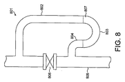
したがって、さらなる態様では、船舶バラスト水タンク用の圧力リリーフ弁が提供されている。かかる船舶バラスト水タンク用の圧力リリーフ弁は、第一の部分と、第二の部分と、第一の部分と第二の部分との間に配置され、使用に当たり、第一の部分と第二の部分との間にシールを形成するように液体を含有するように構成されている中央部分とを備えている。 Accordingly, in a further aspect, a pressure relief valve for a ship ballast water tank is provided. Such a pressure relief valve for a ship ballast water tank is arranged between the first part, the second part, the first part and the second part, and in use, the first part and the second part And a central portion configured to contain a liquid so as to form a seal therewith.
たとえば、導管がU字型に曲げられた配管から形成され、中央部分がU字型配管内に形成され、第一の部分および第二の部分が中央部分からほぼ鉛直に方向に延びている。この構成は、上側デッキがバラストタンクの頂部よりも非常に高くなっている船舶において利用する場合に非常に都合がよい。さらに、バラストタンクから上側デッキレベルにまで延びている既存の導管にぴったりと合って都合がよい。 For example, the conduit is formed from a pipe bent into a U-shape, the central portion is formed in the U-shaped piping, and the first portion and the second portion extend in a substantially vertical direction from the central portion. This configuration is very convenient for use on ships where the upper deck is much higher than the top of the ballast tank. Furthermore, it is convenient to fit in an existing conduit that extends from the ballast tank to the upper deck level.
あるいは、第一の部分および第二の部分がおおむね同軸上の導管により形成されても良い。この構成では、第一の部分の遠位端部が第二の部分にまで延びている。この第二の部分は、シールされた端部を有しある量の流体を受け入れるように構成されているおおむねチューブの形態をしている。したがって、中央部分は、第一の部分の遠位端部と第二の部分のシールされた端部との間に形成されている。この構成は、上側デッキのレベルがバラストタンクの頂部とおおむね同一のレベルに位置している場合に、非常に好都合である。 Alternatively, the first portion and the second portion may be formed by a generally coaxial conduit. In this configuration, the distal end of the first portion extends to the second portion. This second portion is generally in the form of a tube having a sealed end and configured to receive a volume of fluid. Thus, the central portion is formed between the distal end of the first portion and the sealed end of the second portion. This configuration is very convenient when the level of the upper deck is approximately at the same level as the top of the ballast tank.
一定の量の液体は、バラストタンク内の最大許容圧力に応じて選択されることが好ましい。 A certain amount of liquid is preferably selected according to the maximum allowable pressure in the ballast tank.
動作において、好ましくは、第二の部分がバラストタンクに接続され、第一の部分が大気と連通するように構成されている。たとえば窒素の注入によりバラストタンク内の圧力が上昇すると、空気が、置換され、中央部分の流体を泡となって通過する。 In operation, the second part is preferably connected to the ballast tank and the first part is configured to communicate with the atmosphere. For example, when the pressure in the ballast tank rises due to nitrogen injection, the air is replaced and the fluid in the central portion passes through as bubbles.
いうまでもなく、中央部分は、実質的に空気ロックとして作用し、ガスが、第一の部分と第二の部分との間の圧力差と中央部分に含まれる流体の高さにと応じていずれかの方向に流れることを可能としている。 Needless to say, the central part essentially acts as an air lock, depending on the pressure difference between the first part and the second part and the height of the fluid contained in the central part. It can flow in either direction.
いずれの構成であっても、ガスが迅速に一または複数のバラストタンクに進入するまたはそこから出ていくことを可能とするように開弁することができる別個の弁が設けられうる。このことは、バラストタンクを充填するまたはバラストタンクを空にするときに好ましい場合があり、窒素の注入中においては、上述の弁は、ヘッドスペース内に希ガスを保持するために用いられても良い。 In either configuration, a separate valve can be provided that can be opened to allow the gas to quickly enter or leave one or more ballast tanks. This may be preferable when filling the ballast tank or emptying the ballast tank, and during the nitrogen injection, the valve described above may be used to hold a noble gas in the headspace. good.
いうまでもなく、上記の弁は、バラスト水タンクの一体部分であっても良いし、または、既存のバラスト水タンクに都合良く付け加えることができる弁であっても良い。 Needless to say, the above-mentioned valve may be an integral part of the ballast water tank or may be a valve that can be conveniently added to an existing ballast water tank.
いうまでもなく、以下の実施形態、明細書および添付の特許請求の範囲に記載の特徴は、完全なバラスト水処理システムを提供するために、都合に合わせて分離してまたは相互に組み合わせて用いることができる。 It will be appreciated that the features described in the following embodiments, specification and appended claims are used separately or in combination with each other to provide a complete ballast water treatment system. be able to.
一例としておよび添付の図面を参照して、本発明の実施形態をさらに説明する。 Embodiments of the present invention will be further described by way of example and with reference to the accompanying drawings.
図1を参照すると、バラストタンク102とバラスト水ポンプ103とを備えている船舶101(点線により図示)が示されている。
Referring to FIG. 1, a ship 101 (shown by a dotted line) provided with a
ポンプ103は、バラスト水を、導管104および粗いフィルタ105を通して汲み上げ、1mmフィルタ106、25μmフィルタ107および導管108、109、1010、1011を通して、バラストタンク102の中へ移送する。水流量のうちの10%が導管109を通り、さらなるポンプ1012によりベンチュリ型窒素注入器1013を通過させられる。ベンチュリ型窒素注入器では、空気コンプレッサ1014および窒素生成器1015からの加圧窒素が上記のストリームの中へ注入される。窒素が加えられたストリームと窒素が加えられていないストリームとは、導管1011において合流され、約130%の飽和度で、バラストタンク102に進入する。窒素をブクブクと泡立てて放出すると、タンクのヘッドスペース1016が窒素で充填される。バラストタンク102には、モニター1019に接続された窒素センサ1017、1018が設けられている。また、ヘッドスペースには、弁1027(図8および図9には二つの異なる構成の弁が示されている)が設けられている。この弁は、ヘッドスペースの過剰圧力または過少圧力(<60mmH2O)に応答して開弁される。これに代えて、弁1027が、ヘッドスペースの過剰圧力を逃がす機能を有しても良いし、また、任意選択的に追加される配管1020が、ヘッドスペース内および/または空タンク内の窒素含有量がある所望のレベル未満にまで下がった場合に、窒素を注入する機能を有しても良い。
Pump 103 pumps ballast water through
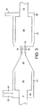
図2には、本発明にかかるバラスト水処理システムを備えているタンカーまたはその他の種類の船舶でありうる従来の二重壁構造を備えた船舶が示されている。かかる船舶は、二重壁構造の船体を備えており、その二重の壁の間に、バラストタンク3が搭載されている。また、この船舶は、推進機関4により駆動される。ポンプ5は、水を、周囲の海からバラスト水処理ユニット7を通して移送させる。窒素は、空気から酸素および窒素を分離させる膜技術などを用いた呼吸ユニットまたは制御大気通気ユニット9から、バラスト水処理ユニット7へ供給される。また、バラスト水処理ユニットには、過剰の熱(たとえば、排気ガスからの熱)またはボイラー8から生成される蒸気が供給される。蒸気発生器は、ほとんどの船舶にすでに一般的に取り付けられている。この蒸気は重油を加熱するために用いられている。バラスト水から放出された酸素は、それと同時にバラスト水システムおよびバラスト水タンクから取り除かれ、個別のタンクまたはタンクの集合に接続されている換気装置29を通るかまたは配管11、12を介した一体式タンク換気システムを通り、そして、ガス制御ユニット9を通って大気中へ放出される。水は、配管10を通じてバラストタンクの中へポンプにより移送される。配管11、12は、バラストタンクの頂部をガス制御ユニット9へ繋いで、バラストタンク内のガス含有量を制御している。この構成が実現可能でない船舶の場合、換気は、従来直接にデッキ上方に向けて行われていたが、空気が個々のタンクの中に吸引されないことを担保するために、過剰圧力弁により管理される。また、図2に示されているシステムは、バラスト水処理ユニット7の前に任意選択的にフィルタユニットを備えても良い。
FIG. 2 shows a ship with a conventional double wall structure, which can be a tanker or other type of ship equipped with a ballast water treatment system according to the present invention. Such a ship has a double-walled hull, and a
図3には、バラスト水処理ユニット7が示されている。このバラスト水処理ユニット7は、流入口側バラスト水配管6と一体になっているシリンダ形状の採取チャンバ21を備えている。シリンダ形状採取チャンバ21の後に、円錐形状のセクション22が形成され、そして幅狭のシリンダ形状のチューブ23が形成されている。シリンダ形状のチューブ23は、キャビテーションチャンバ24として作用する幅広のセクションまたはチャンバへ接続されている。円錐形状のセクション22および/または幅狭のシリンダ形状のチューブ23は、らせん状の縁部または羽根部32を備えうる。この羽根部32は、回転運動を誘発して、流体を通過させる推進力を引き起こすようになっている。
FIG. 3 shows a ballast water treatment unit 7. The ballast water treatment unit 7 includes a
採取チャンバ21には、一または複数の注入チューブ25が挿入されているかまたは組み入れられている。この/これらの注入チューブ25は、外部ユニット8、9から蒸気および窒素ガスを受け取り、そのガスを採取チャンバ21へ移送するようになっている。これらのガスは、注入チューブ25に入る直ぐ前の混合チャンバ(図示せず)内で混合されても良いし、流入口側バラスト水配管6の周りの環状のマニフォールド26内で混合されても良い。ガス混合物は、採取チャンバ21内で水と混合される。採取チャンバ21の周辺において複数のガス注入チューブ25を用いることが好ましい。
One or
先と場合と同様に構成されている一または複数の小さなガス流出チューブがキャビテーションチャンバ24に挿入されても良いしまたは組み込まれても良い。このチェンバの周辺の開口部は、除去された酸素を取り除くための換気装置として作用する。これらのチューブはガス流出口マニフォールド28に至る。マニフォールド28は、通気配管29により、ガス制御ユニット9に接続されている。キャビテーションチャンバ24の周辺において複数のガス流出チューブ27を用いることが好ましい。しかしながら、単一のガス流出チューブ27のみを用いることも可能である。
One or more small gas outlet tubes, configured as before, may be inserted into or incorporated into the
動作において、海水は、バラスト水用ポンプ5によりシリンダ形状の採取チャンバ21の中へ、さらに、円錐形状のセクション22を通ってシリンダ形状のチューブ23へ、それから、キャビテーションチャンバ24の中へと供給される。キャビテーションまたは準キャビテーションが発生する物理的状態は、バラスト水の粘稠度、すなわちその蒸気点を操作し、内部流体圧力を下げることにより達成される。シリンダ形状のチューブとキャビテーションチャンバとの間の縁部20において、キャビテーションは開始される。シリンダ形状のチューブでは、流体の速度が上昇し、静水圧が、修正されたバラスト水(流体)の蒸気点にまたはその近傍にまで下降し、泡が形成されることになる。らせん状の縁部または羽根部32は、シリンダ形状のチューブ23とキャビテーションチャンバ24との間の縁部20における飛躍的な圧力の変化と相俟って、上記の泡の破壊を開始する。これらの作用は、流体力を起こし、泡が内破し、圧力インパルスとしてエネルギーを放出し、温度をピークにまで上昇させる。
In operation, seawater is fed by the ballast water pump 5 into the cylinder-shaped
水の速度は、蒸気と窒素との混合物がガス供給チューブからの水に進入することによるジェット作用によって上昇される。蒸気は、速度上昇効果の発揮に必要とされる量が非常に制限された量でしかないので、水温に対しては、無視できる程度の影響しか及ぼさない。この速度上昇効果は、窒素の密度の急速な変化のため窒素の体積が上昇するので、さらに促進される。泡により、水のレオロジー的な物性、たとえば総合密度および総合粘度が変わる。窒素が周辺の水により冷却されるに従って、一部が泡を形成し、一部が水に徐々に溶けていく。この工程により、酸素の放出が開始される。 The water velocity is increased by the jet action due to the mixture of steam and nitrogen entering the water from the gas supply tube. Steam only has a negligible effect on the water temperature because only a very limited amount is needed to exert the speed-increasing effect. This speed increasing effect is further promoted because the volume of nitrogen increases due to the rapid change in nitrogen density. Foam changes the rheological properties of water, such as total density and total viscosity. As nitrogen is cooled by the surrounding water, some will form bubbles and some will gradually dissolve in the water. By this step, release of oxygen is started.
シリンダ形状のチューブ23を通過し、挿入された縁部20の作用に晒されたあと、形成された泡は、キャビテーションチャンバ24への進入時点において崩壊していく。泡の内破により、水中に存在する有機細胞膜および有機細胞組織が破壊される。飛躍的な圧力変化を発生させるキャビテーションチャンバの特徴的な設計により、安定したかつ制御されたキャビテーション作用が発生する。
After passing through the cylinder-shaped
キャビテーション作用の効果は、水中に存在する酸素の大部分が放出されることにある。この酸素は、キャビテーションチャンバの周囲のガス流出チューブ27によりまたは船舶タンク換気システムを通じて取り除かれる。流体を飽和するに至っていない余剰の窒素により、キャビテーションにより放出された酸素が置換され、プロセスの途中でまたは水がバラストタンク3に入ったあと、水による再度の吸収および溶解が防止される。
The effect of the cavitation action is that most of the oxygen present in the water is released. This oxygen is removed by a
バラスト水処理ユニットは、シリンダ形状採取チャンバ21と、円錐形状のセクション22と、シリンダ形状のチューブ23とを備えているものとして記載されている。これは、現在における本発明の好ましい実施形態である。しかしながら、これらの部材は、図4に示されているように、単一のテーパ部33と交換することが最適である場合もある。また、ガスは、テーパセクション33の円周に沿ってかつ長手方向に沿って設けられた複数のチューブ状の開口部34から、すなわち多段式注入方式で注入されても良い。この実施形態では、環状のガスマニフォールドはテーパセクション33の外側上のかつこのテーパセクションの全長に沿ったチャンバまたはボックス35として設計されうる。
The ballast water treatment unit is described as comprising a cylinder-shaped
酸素含有量が典型的には2mg/mlと低く活性生物が少ないバラスト水が、キャビテーションチャンバからバラストタンクへ供給される。この低い酸素含有量は、除去作用または殺戮作用をさらに向上させ、再生の可能性を排除するように作用する。酸素の存在によるまたはそれに依存する腐食およびコーティングの劣化が著しく削減される。 Ballast water having a low oxygen content, typically 2 mg / ml, and low active organisms is supplied from the cavitation chamber to the ballast tank. This low oxygen content acts to further improve the scavenging or killing action and eliminate the possibility of regeneration. Corrosion and coating degradation due to or dependent on the presence of oxygen is significantly reduced.
バラストタンクを空にするとき、ガス制御ユニット9は、窒素をバラストタンクに供給して、酸素または空気の侵入を防止し、これにより、タンクが水を含んでいないときも酸素量の少ない雰囲気を維持するように管理している。このガスは配管11を通じて供給されるようになっている。従来のシステムでは、バラストタンクが水を含んでいないときに、通気用のチューブが外部の空気をバラストタンクに供給していた。しかしながら、本発明は、バラストタンク内に非腐食性雰囲気を担保する閉鎖型ガス制御システム(closed gas control system)を備えている。誰かがタンク内に入ろうとしている場合、ガス制御ユニット9は、配管12を通じて、窒素雰囲気を正常な呼吸可能な空気と置換する。
When emptying the ballast tank, the
換気用の配管11、12が含まれていない場合、換気は、換気装置(図示せず)を通じて空気を入れることにより担保される。
If the
図5は、バラスト水処理のための本発明にかかる構成を示す概略図である。矢印は、船舶がバラスト水を充填しているときの流れの方向を示している。水は、配管36を通じて、周辺の海から船舶に入って来ている。この水は、第一の3方向制御弁40により、ポンプ5に案内されている。ポンプ5は配管6を通じて水処理ユニット7に給水する。蒸気および窒素ガスは、配管30、31により、水処理ユニット7へ供給され、除去された酸素は、配管29およびガス制御ユニット9を通じて取り除かれる。最終的には、その酸素は配管39により大気中に排出される。処理後、水は、配管10および第二の3方向弁41を通じて、バラストタンク3の中へポンプにより移送される。水はバラストタンク3の中のガスを置換し、そのガスは配管12を通じて除去される。
FIG. 5 is a schematic diagram showing a configuration according to the present invention for ballast water treatment. The arrows indicate the direction of flow when the ship is filled with ballast water. Water enters the ship from the surrounding sea through the
排出は、水がポンプにより再び上述のようにシステムを通過、処理されるように、構成されても良い。このとき、水が、窒素に代えて、注入用の配管31を通じて酸素または空気にさらされても良い。この目的は、排出の行われる港または領域がすでに酸素レベルが不十分となっている場合に酸素量の少ない水を排出しないようにすることを担保することにある。このことが図6に示されている。バラスト水は、配管37、第一の3方向弁40、ポンプ5、水処理ユニット7および第二の3方向弁41を通じてバラストタンク3から出され、配管38を通じて周辺の海へ排出される。この場合、蒸気は、配管30を通じて供給され、空気または酸素は配管31を通じて供給される。したがって、海に排出される水は酸素含有量を回復している。バラストタンク内に酸素が除去された雰囲気を維持するために、バラストタンク3から取り除かれる水は、配管11を通じてガス制御ユニット9から供給される窒素ガスと置換される。
The discharge may be configured such that the water is again passed through the system and processed by the pump as described above. At this time, water may be exposed to oxygen or air through the piping 31 for injection instead of nitrogen. The purpose is to ensure that the port or area where the discharge takes place does not discharge low oxygen water when the oxygen level is already insufficient. This is illustrated in FIG. Ballast water is discharged from the
本発明が船舶内のバラスト水の処理のためのシステムおよび方法として記載されているが、他の用途に用いられても良い。そのような一つの用途は、廃水処理、たとえば下水処理である。夏の時期には、産業用のプラント、たとえば廃棄物焼却炉から余ったエネルギーが利用可能となる。焼却炉は、キャビテーションユニットを駆動するエネルギーおよび酸素除去用のガスを供給しうる。二酸化酸素は酸素除去用のガスとして用いても良い。というのは、上記の状態下では、このガスの腐食作用が少しも発生しないからである。他の用途は、大規模空調プラントまたは飲食物処理産業におけるバクテリアレベルの管理である。これらの他の用途は、本発明の一部を形成し、バラスト水とは異なり下水などにのみ適用するために変形された添付のクレームに記載されうる。 Although the present invention has been described as a system and method for the treatment of ballast water in ships, it may be used for other applications. One such application is wastewater treatment, such as sewage treatment. In summer, surplus energy is available from industrial plants, such as waste incinerators. The incinerator can supply energy for driving the cavitation unit and gas for oxygen removal. Oxygen dioxide may be used as a gas for removing oxygen. This is because no corrosive action of this gas occurs under the above conditions. Another application is bacterial level management in large air conditioning plants or the food processing industry. These other uses may form part of the present invention and be set forth in the appended claims modified to apply only to sewage and the like, unlike ballast water.
図7は、船舶が沿岸警備当局へバラストタンクを空にした場所および日時を示すデータを提供する構成を示している。 FIG. 7 shows an arrangement for providing data indicating where and when the ship emptied the ballast tank to the coast guard authorities.
船舶701には、バラストタンク702と排出ポンプ703が設けられている。排出ポンプは、船舶の制御システム(図示せず)により制御され、バラスト水制御ユニット705に向かう制御回線704に信号を送信するように構成されている。バラスト水制御ユニット705は、GPS受信機706から船舶の座標を示すGPS信号を受信する。また、制御ユニット705は、沿岸警備当局708に対しておよびそこからデータを送受信するための衛星用送受信機707へ接続されている。
The
動作において、制御ユニットは、バラスト水を排出ための要件、すなわち海岸からの距離を示すデータを沿岸警備当局から受信する。このデータは制御ユニット内に格納される。制御ユニットは、GPS受信機から船舶の座標を受信し、このデータを格納する。排出用ポンプが作動されると、制御ユニット705は、制御信号を受信し、それらのポンプが作動された時間および場所を記録する。次いで、このデータは、自動的に沿岸警備当局へ伝達され、該当する法律を船舶が順守しているか否かを知らせる。
In operation, the control unit receives data from the coast guard authority indicating the requirements for discharging ballast water, i.e. the distance from the coast. This data is stored in the control unit. The control unit receives the coordinates of the ship from the GPS receiver and stores this data. When the evacuation pumps are activated, the
他の実施形態では、制御ユニットは、バラストタンクを廃水するための法的な限界値に近づいていることを船舶の乗船員に知らせるように構成されうる。 In other embodiments, the control unit may be configured to inform the ship occupant that the legal limit for draining the ballast tank is approaching.
図8には、第一の構成に従うバラストタンク圧力弁が示されている。 FIG. 8 shows a ballast tank pressure valve according to the first configuration.
弁801は、第一の部分802がU断面の中央部803に接続されて形成されている。このU断面803は、第二の部分804に接続されている。第一の部分802および第二の部分804は縦長の導管805に接続されている。この導管は、その下側でバラストタンク(図示せず)に接続され、その上側で大気に接続されている。導管805には、充填中および空にする間にタンクの中へおよびタンクの外へ空気を移動させることを可能とするための弁806が設けられている。
The
動作において、バラストタンクは弁806を開弁して充填される。バラストタンクが満タンになると、弁806が閉弁される。次いで、窒素が、ヘッドスペースの中に注入され、ヘッドスペース内の空気を移動させ、圧力を上昇させる。圧力が上昇するに従って、空気は
U形状の部分803内の液体807の中をブクブクと泡を立てながら通過する。液体のレベルにより、空気がブクブクと泡を立てて通過する圧力が規定される。
In operation, the ballast tank is filled by opening valve 806. When the ballast tank is full, the valve 806 is closed. Nitrogen is then injected into the headspace, moving the air in the headspace and increasing the pressure. As the pressure increases, air passes through the liquid 807 in the
いったん空気が置き換えられると、この弁は、第一の部分と第二の部分との差圧の変化に従って、バラストタンクの中へおよびバラストタンクの外へガスを移動させることができる。 Once the air is replaced, the valve can move gas into and out of the ballast tank according to changes in the differential pressure between the first and second portions.
図9は、第二の構成にかかるバラストタンク圧力弁が示されている。 FIG. 9 shows a ballast tank pressure valve according to the second configuration.
弁901は、シールされたチューブまたは「ドラム」として形成された第二の部分の中へ第一の部分902が延びている構成に形成されている。第一の部分と第二の部分との間には、接続部分903によりシールが形成され、第二の部分903内にキャビティが形成されている。このキャビティ905は、導管906を通じて、バラストタンク(図示せず)と連通している。
The
この構成では、キャビティ905内の圧力は、バラストタンク内の圧力が上昇するに従って上昇する。第二の部分903は、液体907で部分的に充填され、この液体が第一の部分と第二の部分との間の空気ロックとして作用するようになっている。第一の構成にかかる弁を参照して先に記載した同様の方法で、圧力が上昇すると、ガスは、液体をブクブクと泡を立てて通過し、第一の部分902を通って大気中に排出される。同様に、バラストタンク内における過剰の圧力は弁によって自動的に逃がされる。
In this configuration, the pressure in the
いうまでもなく、本明細書記載のタイプのバラスト水圧力弁を実現するために、一連の範囲の異なる導管構成および液体レベルを用いることができる。 Needless to say, a series of different ranges of conduit configurations and liquid levels can be used to implement a ballast water pressure valve of the type described herein.
Claims (32)
水を、水源(たとえば、周囲の海、湖または河川)からフィルタを通して、水上を航行している船舶のバラストタンクへと、ポンプにより移送することと、
前記ポンプによる移送を停止したときの前記バラストタンク内の前記水が、当該水の窒素飽和含有量を超えているとともに酸素飽和含有量未満であるように、前記水のうちの少なくとも一部の溶融窒素含有量を、前記窒素飽和含有量を超えるレベルまで上昇させることと、
前記バラストタンクのヘッドスペース内を、大気の窒素含有量(モル%)よりも大きな窒素含有量を有する雰囲気に維持することと、
水を、前記バラストタンクから前記船舶の周辺の水の中にポンプにより移送させることと、
前記バラストタンクから前記ポンプにより移送される前記水を、前記船舶の周辺の水の中に排出するまえに、微生物を殺す処理を加えることと
を含む、方法。 A method for treating ballast water, comprising:
Pumping water from a water source (eg, surrounding sea, lake or river) through a filter to the ballast tank of a vessel navigating over the water;
Melting at least a portion of the water so that the water in the ballast tank when transfer by the pump is stopped is above the nitrogen saturation content of the water and below the oxygen saturation content Increasing the nitrogen content to a level above the nitrogen saturation content;
Maintaining the inside of the head space of the ballast tank in an atmosphere having a nitrogen content greater than the nitrogen content (mol%) of the atmosphere;
Pumping water from the ballast tank into the water around the vessel;
Adding a process of killing microorganisms before discharging the water transferred by the pump from the ballast tank into the water around the ship.
水を、フィルタを通してバラストタンクの中に移送するための第一のポンプと、
前記第一のポンプにより水が通過させられうるフィルタと、
水を、前記第一のポンプから前記フィルタを通して前記バラストタンクまで搬送するための導管と、
前記第一のポンプから前記バラストタンクまでポンプにより移送されている水の中に窒素を注入するための窒素注入器と、
任意選択的な、前記窒素注入器に取り付けられているまたは取り付け可能な窒素供給源と、
水を、前記バラストタンクから導管を通って前記船舶の外へ移送するための(任意選択的に前記第一のポンプであることが好ましい)第二のポンプと、
前記バラストタンクから前記船舶の外へポンプにより移送されている水の中の微生物を殺すように構成されている微生物を殺すユニットと
を備えてなる、装置。 An apparatus for treating ballast water of a ship navigating on the water,
A first pump for transferring water through the filter into the ballast tank;
A filter through which water can be passed by the first pump;
A conduit for transporting water from the first pump through the filter to the ballast tank;
A nitrogen injector for injecting nitrogen into the water being pumped from the first pump to the ballast tank;
An optional nitrogen source attached to or attachable to the nitrogen injector;
A second pump (optionally preferably the first pump) for transferring water from the ballast tank through a conduit and out of the vessel;
A microbe killing unit configured to kill microbes in water being pumped out of the ship from the ballast tank.
水を、水源(たとえば、周囲の海、湖または河川)からフィルタを通して、水上を航行している船舶の前記バラストタンクへと、ポンプにより移送することと、
水を、前記バラストタンクから前記船舶の周辺の水の中へポンプにより移送させることと、
前記バラストタンクに対しておよび前記バラストタンクから前記ポンプにより移送される前記水を、前記船舶の周辺の水の中に排出するまえに、微生物を殺す処理を加えることと
を含む、方法。 A method for treating ballast water, comprising:
Pumping water from a water source (e.g., surrounding sea, lake or river) through a filter to the ballast tank of a vessel navigating over the water;
Pumping water from the ballast tank into the water around the vessel;
Adding a process of killing microorganisms to the ballast tank and before the water transferred by the pump from the ballast tank is discharged into the water around the vessel.
水を、フィルタを通してバラストタンクの中に移送するための第一のポンプと、
前記第一のポンプにより水が通過させられうるフィルタと、
水を、前記第一のポンプから前記フィルタを通して前記バラストタンクまで搬送するための導管と、
前記バラストタンクに対しておよび前記バラストタンクからポンプにより移送されている水の中の微生物を殺すように構成されている微生物を殺すユニットと
を備えてなる、装置。 An apparatus for treating ballast water of a ship navigating on the water,
A first pump for transferring water through the filter into the ballast tank;
A filter through which water can be passed by the first pump;
A conduit for transporting water from the first pump through the filter to the ballast tank;
A microorganism killing unit configured to kill microorganisms in the water being pumped to and from the ballast tank.
請求項2、4および6のうちのいずれか一つに記載の装置をさらに備えてなることを特徴とする、船舶。 A ship navigating on the water with a ballast water tank,
A ship further comprising the device according to any one of claims 2, 4 and 6.
第一の容器から水をポンプにより移送することと、
前記水に蒸気を加えることと、
前記水にさらなるガス状の材料を加えることと、
前記水にキャビテーション作用を加えることと、
前記水を第二の容器に移送することと
を含む、方法。 A method for treating ballast water, comprising:
Pumping water from the first container;
Adding steam to the water;
Adding further gaseous material to the water;
Adding a cavitation action to the water;
Transferring the water to a second container.
前記水に蒸気を加える手段と、
前記水にさらなるガス状の材料を加える手段と、
前記水にキャビテーション作用を加える手段と、
前記水を第二の容器に移送する手段と
を備えてなる、システム。 A system for treating ballast water comprising a pump for transferring water from a first container,
Means for adding steam to the water;
Means for adding further gaseous material to the water;
Means for adding a cavitation action to the water;
Means for transferring said water to a second container.
バラスト水を前記液体処理機器(7)に供給する液体流入配管(6)と、
前記流入配管(6)に接続されている採取チャンバ(21)と、
前記採取チャンバ(21)に接続されている円錐形状のセクション(22)と、
前記円錐形状のセクション(22)に接続されているチューブ(23)と、
前記チューブ(23)に接続されているキャビテーションチャンバ(24)と、
前記キャビテーションチャンバ(24)に接続されているとともに前記キャビテーションチャンバ(24)から前記液体を移送する液体流出チューブと、
前記採取チャンバ(21)へ、蒸気およびさらなるガス状の材料を供給する少なくとも一つのガス供給チューブ(25)とを備えてなる、機器。 An apparatus for treating ballast water used in the apparatus according to claim 4,
A liquid inflow pipe (6) for supplying ballast water to the liquid treatment device (7);
A collection chamber (21) connected to the inlet pipe (6);
A conical section (22) connected to the collection chamber (21);
A tube (23) connected to the conical section (22);
A cavitation chamber (24) connected to the tube (23);
A liquid outflow tube connected to the cavitation chamber (24) and for transferring the liquid from the cavitation chamber (24);
An apparatus comprising at least one gas supply tube (25) for supplying vapor and further gaseous material to the collection chamber (21).
液体を前記液体処理機器(7)に供給する液体流入配管(6)と、
前記流入配管(6)に接続されているテーパセクション(33)と、
前記テーパセクション(33)に接続されているキャビテーションチャンバ(24)と、
前記キャビテーションチャンバ(24)に接続されているとともに該キャビテーションチャンバ(24)から前記液体を移送する液体流出チューブ(10)と、
前記採取チャンバ(21)へ、蒸気およびさらなるガス状の材料を加える手段(34)とを備えてなる、機器。 A device (7) for treating ballast water used in the apparatus according to claim 4,
A liquid inflow pipe (6) for supplying liquid to the liquid processing equipment (7);
A tapered section (33) connected to the inlet pipe (6);
A cavitation chamber (24) connected to the tapered section (33);
A liquid outflow tube (10) connected to the cavitation chamber (24) and transferring the liquid from the cavitation chamber (24);
A means (34) for adding vapor and further gaseous material to the collection chamber (21).
制御ユニットと、
データ格納手段とを備えており、
前記制御ユニットが、バラスト水タンクが空にされたという知らせおよび船舶の座標の知らせを受信し、前記データ格納手段内に両方の知らせを格納するように構成されてなる、システム。 A ballast water control system,
A control unit;
Data storage means,
A system wherein the control unit is configured to receive a notification that a ballast water tank has been emptied and a notification of the coordinates of a vessel and store both notifications in the data storage means.
Applications Claiming Priority (3)
| Application Number | Priority Date | Filing Date | Title |
|---|---|---|---|
| GB0410478A GB0410478D0 (en) | 2004-05-11 | 2004-05-11 | Method |
| NO20045500A NO330147B1 (en) | 2004-12-16 | 2004-12-16 | Method, arrangement and apparatus for treating ballast water |
| PCT/GB2005/001838 WO2005108301A1 (en) | 2004-05-11 | 2005-05-11 | Ballast water system |
Publications (2)
| Publication Number | Publication Date |
|---|---|
| JP2007537036A true JP2007537036A (en) | 2007-12-20 |
| JP2007537036A5 JP2007537036A5 (en) | 2008-06-19 |
Family
ID=34967574
Family Applications (1)
| Application Number | Title | Priority Date | Filing Date |
|---|---|---|---|
| JP2007512345A Pending JP2007537036A (en) | 2004-05-11 | 2005-05-11 | Ballast water system |
Country Status (6)
| Country | Link |
|---|---|
| US (1) | US20080277354A1 (en) |
| EP (1) | EP1751063A1 (en) |
| JP (1) | JP2007537036A (en) |
| KR (1) | KR100881962B1 (en) |
| AU (1) | AU2005240411B2 (en) |
| WO (1) | WO2005108301A1 (en) |
Cited By (9)
| Publication number | Priority date | Publication date | Assignee | Title |
|---|---|---|---|---|
| JP2010523328A (en) * | 2007-04-12 | 2010-07-15 | シー ナイト,コーポレーション | Field ballast water treatment system and method |
| JP2011072873A (en) * | 2009-09-29 | 2011-04-14 | Sumitomo Heavy Industries Marine & Engineering Co Ltd | Ballast water treatment apparatus |
| JP2011518038A (en) * | 2008-04-23 | 2011-06-23 | 青▲島▼海▲徳▼威科技有限公司 | A kind of low current electrolysis sterilization algae device and method |
| JP2011519717A (en) * | 2008-04-18 | 2011-07-14 | エコマリネ アーベー | How to handle offshore objects |
| JP2012245852A (en) * | 2011-05-26 | 2012-12-13 | Mitsubishi Heavy Ind Ltd | Liquefied fuel transporting vessel, method of converting vessel, vessel, and liquefied fuel transporting vessel |
| WO2013081289A1 (en) * | 2011-11-30 | 2013-06-06 | 삼성중공업 주식회사 | Thruster system and ship including same |
| CN103442982A (en) * | 2011-03-03 | 2013-12-11 | 巴瓦特股份公司 | System for treating ballast water in ballast tanks |
| JP2017185884A (en) * | 2016-04-05 | 2017-10-12 | テククロス・カンパニー・リミテッド | Ballast water treatment operation device and method |
| JP2020080858A (en) * | 2018-11-20 | 2020-06-04 | Jfeエンジニアリング株式会社 | Cell wall destructor and sludge processing device using the same |
Families Citing this family (37)
| Publication number | Priority date | Publication date | Assignee | Title |
|---|---|---|---|---|
| WO2005122054A2 (en) | 2004-01-22 | 2005-12-22 | The Glosten Associates, Inc. | Apparatus and method of vessel emission management |
| DE102005013673A1 (en) * | 2005-03-24 | 2006-09-28 | Hydac Process Technology Gmbh | Filter system and method for operating the filter system |
| RU2433087C2 (en) * | 2005-10-28 | 2011-11-10 | Ризос Балласт Текнолоджиз (Препрайэтри) Лимитед | Method of disinfecting water by destroying aquatic organisms and apparatus for realising said method |
| DE102006045558A1 (en) * | 2006-09-25 | 2008-04-03 | Rwo Gmbh | Water treatment plant |
| JP5408661B2 (en) | 2006-10-20 | 2014-02-05 | オーシャンセイバー エーエス | Ballast water treatment apparatus and ballast water treatment method |
| JP2008221122A (en) * | 2007-03-12 | 2008-09-25 | Sumitomo Heavy Ind Ltd | Water treatment device |
| EP1975130A3 (en) * | 2007-03-27 | 2011-03-30 | JOWA GERMANY GmbH | Method for removing plant growth from ballast water in ships |
| US20100072143A1 (en) * | 2007-04-26 | 2010-03-25 | Bernard Jacobs | Water treatment system |
| US9266752B2 (en) | 2007-08-02 | 2016-02-23 | Ecosphere Technologies, Inc. | Apparatus for treating fluids |
| SE535052C2 (en) | 2009-01-20 | 2012-03-27 | Gva Consultants Ab | Seawater systems and floating vessels including such a system |
| WO2011049546A1 (en) * | 2009-10-20 | 2011-04-28 | Enviro Tech As | Apparatus for installation of ultraviolet system for ballast water treatment in explosive atmosphere of shipboard pump rooms and offshore platforms |
| US9546351B2 (en) | 2010-04-12 | 2017-01-17 | Industrias Centli, S.A. De C.V. | Method and system for processing biomass |
| IT1404266B1 (en) * | 2011-02-10 | 2013-11-15 | E Pic S R L | PLANT AND METHOD FOR THE TREATMENT OF FLUIDS. |
| ITMI20111127A1 (en) * | 2011-06-21 | 2012-12-22 | Artes Ingegneria S P A | METHOD AND MODULAR SYSTEM FOR THE STERILIZATION OF BORN WATERS |
| CN102491569B (en) * | 2011-11-30 | 2013-06-19 | 江苏南极机械有限责任公司 | Marine ballast water treatment system |
| JP5831327B2 (en) * | 2012-03-28 | 2015-12-09 | 栗田工業株式会社 | Remote monitoring device and remote monitoring method for ballast water treatment system |
| KR101250349B1 (en) * | 2012-06-29 | 2013-04-03 | 주식회사 신영이앤아이 | A method for the removal of aqueous nitrogen from the wastewater |
| WO2014073105A1 (en) * | 2012-11-12 | 2014-05-15 | 三浦工業株式会社 | Ballast water treatment device |
| US10370263B2 (en) | 2012-11-12 | 2019-08-06 | Miura Co., Ltd. | Ballast water treatment device |
| DK2920064T3 (en) | 2012-11-14 | 2017-11-20 | Ballast Water Monitoring As | PROCEDURE AND SYSTEM FOR MONITORING THE QUALITY OF BALLAST WATER FROM A VESSEL |
| KR101269578B1 (en) | 2013-04-24 | 2013-06-05 | 삼건세기(주) | Operating method for treating a ballast water |
| KR101520586B1 (en) * | 2014-08-11 | 2015-05-15 | 연세대학교 산학협력단 | Apparatus and method for treating ballast water |
| WO2016029185A1 (en) * | 2014-08-21 | 2016-02-25 | Coating Systems Laboratories, Inc. | Ballast water treatment systems |
| CN107428408A (en) * | 2015-01-15 | 2017-12-01 | 巴瓦特股份公司 | For configuring the method and related system of ballast water treatment system |
| EP3350130A4 (en) * | 2015-09-18 | 2019-03-13 | Evoqua Water Technologies LLC | In-situ delivery systems for reaction product abatement in electrochemical cells |
| US10214274B2 (en) * | 2016-04-05 | 2019-02-26 | Techcross Co. Ltd. | Ballast water treatment operating apparatus and method |
| US11254395B2 (en) | 2016-09-09 | 2022-02-22 | Richard L. Hartman | Aquatic invasive species control apparatuses and methods for watercraft |
| WO2018058011A1 (en) * | 2016-09-23 | 2018-03-29 | Evoqua Water Technologies Llc | Ballast water treatment and neutralization |
| US10640394B2 (en) | 2016-12-31 | 2020-05-05 | Ugsi Solutions, Inc. | Systems and methods for removing volatile compounds from water-storage tanks |
| WO2018207071A1 (en) * | 2017-05-08 | 2018-11-15 | Jeremic Milan | Method for liquid purification by hydrodynamic cavitation and device for carrying out said method |
| BR102018000893A2 (en) * | 2018-01-16 | 2018-09-04 | Nbs Engenharia Ltda Me | system and equipment for the treatment of sewage by hydrocavitation and advanced oxidation, associated with biological systems, with or without media (mbbr) to meet varying flows, and capable of treating effluents with industrial and domestic characteristics; with nutrient removal, coliform reductions that enable reuse of final effluent |
| EP3666640A1 (en) * | 2018-12-14 | 2020-06-17 | ABB Schweiz AG | Water treatment device |
| WO2020212502A1 (en) * | 2019-04-16 | 2020-10-22 | Minox Technology As | System and method for mixing gas and fluids |
| CN110526463B (en) * | 2019-09-26 | 2021-08-10 | 烟台金能机械有限公司 | A environment-friendly effluent treatment plant for industrial production |
| US20210147272A1 (en) * | 2019-11-20 | 2021-05-20 | Hyperion H2O LLC | Water Treatment System and Method |
| US11027987B1 (en) * | 2019-11-20 | 2021-06-08 | Andy Andalibian | Ballast water, bilge water, slop water, or oily water treatment system |
| CN116353811B (en) * | 2023-05-31 | 2023-07-28 | 中交第一航务工程局有限公司 | Leveling method and leveling system for full-floating leveling ship |
Citations (3)
| Publication number | Priority date | Publication date | Assignee | Title |
|---|---|---|---|---|
| JP2001509729A (en) * | 1996-11-27 | 2001-07-24 | ブラウニング トランスポート マネージメント、インコーポレイテッド | Method and apparatus for sterilizing microorganisms in ship ballast water |
| JP2003514648A (en) * | 1999-11-15 | 2003-04-22 | フォーリノーバ、アクティーゼルスカブ | Method and apparatus for regulating undesirable organisms in water systems |
| WO2003093176A2 (en) * | 2002-05-02 | 2003-11-13 | Peter Drummond Mcnulty | Apparatus and method for water treatment |
Family Cites Families (25)
| Publication number | Priority date | Publication date | Assignee | Title |
|---|---|---|---|---|
| US3594115A (en) * | 1968-02-09 | 1971-07-20 | Electro Hydraulics Corp | Bacteria destruction methods |
| US4084757A (en) * | 1976-08-05 | 1978-04-18 | Vladimir Jurievich Rakitin | Apparatus for continuous disintegration of cells of microorganisms |
| US4259360A (en) * | 1979-04-16 | 1981-03-31 | Liquid Carbonic Corporation | Deoxygenation of liquids |
| GB2145937A (en) * | 1983-07-07 | 1985-04-11 | British Hydromechanics | Contacting a gas and a liquid to remove an unwanted gas |
| US4931225A (en) * | 1987-12-30 | 1990-06-05 | Union Carbide Industrial Gases Technology Corporation | Method and apparatus for dispersing a gas into a liquid |
| DE3818237A1 (en) * | 1988-05-28 | 1989-11-30 | Bran & Luebbe | HIGH PRESSURE HOMOGENIZER |
| US4969983A (en) * | 1988-07-11 | 1990-11-13 | Ionics, Incorporated | Apparatus and process for the removal of acidic and basic gases from fluid mixtures using bipolar membranes |
| JP2794438B2 (en) * | 1989-02-16 | 1998-09-03 | 本多電子株式会社 | Cleaning method using cavitation |
| US5190670A (en) * | 1990-03-16 | 1993-03-02 | Pec Research, Inc. | Process and system for separating and condensing contaminants from a liquid |
| US5049400A (en) * | 1990-07-02 | 1991-09-17 | Hayden Steven M | Apparatus and method for treatment of various liquid or slurry by ultrasonification in conjunction with heat and pressure |
| US5587081A (en) * | 1994-04-26 | 1996-12-24 | Jet-Tech, Inc. | Thermophilic aerobic waste treatment process |
| US5893233A (en) * | 1994-05-03 | 1999-04-13 | Board Of Regents Of The University Of Wisconsin System On Behalf Of The University Of Wisconsin-Milwaukee | Displacement of zebra mussels |
| US5476595A (en) * | 1994-05-18 | 1995-12-19 | The University Of Western Ontario | Zebra mussel control device for water intakes |
| WO1995032052A1 (en) * | 1994-05-20 | 1995-11-30 | U.S. Filter/Ionpure, Inc. | Polarity reversal and double reversal electrodeionization apparatus and method |
| US5816181A (en) * | 1996-02-14 | 1998-10-06 | Sherman, Jr.; Thomas W. | Ballast water treatment system |
| GB9701797D0 (en) * | 1997-01-29 | 1997-03-19 | Univ Coventry | Cavitation inducer |
| US6126842A (en) * | 1998-01-30 | 2000-10-03 | Decker; R. Scott | Low-concentration ozone waste water treatment |
| WO1999048588A1 (en) * | 1998-03-20 | 1999-09-30 | Mazzei Angelo L | Stripping of contaminants from water |
| US6200486B1 (en) * | 1999-04-02 | 2001-03-13 | Dynaflow, Inc. | Fluid jet cavitation method and system for efficient decontamination of liquids |
| GB0106483D0 (en) * | 2001-03-16 | 2001-05-02 | Ws Atkins Consultants Ltd | Improvemnts relating to fluid processing devices |
| US6761123B2 (en) * | 2001-05-25 | 2004-07-13 | Mh Systems | Infusion of combustion gases into ballast water preferably under less than atmospheric pressure to synergistically kill harmful aquatic nuisance species by simultaneous hypercapnia, hypoxia and acidic ph level |
| US7381338B2 (en) * | 2002-04-17 | 2008-06-03 | Nutech 03, Inc. | Ballast water treatment system and method without off-gas |
| US20030205136A1 (en) * | 2002-05-02 | 2003-11-06 | Mcnulty Peter Drummond | System and method of water treatment |
| EP1517860A4 (en) * | 2002-06-29 | 2006-05-10 | Marenco Group | Ballast water treatment systems including related apparatus and methods |
| DE20302516U1 (en) * | 2003-02-15 | 2003-12-11 | Hamann Ag | Plant for the removal and deactivation of organisms in ballast water |
-
2005
- 2005-05-11 US US11/596,179 patent/US20080277354A1/en not_active Abandoned
- 2005-05-11 JP JP2007512345A patent/JP2007537036A/en active Pending
- 2005-05-11 AU AU2005240411A patent/AU2005240411B2/en not_active Ceased
- 2005-05-11 WO PCT/GB2005/001838 patent/WO2005108301A1/en active Application Filing
- 2005-05-11 KR KR20067023651A patent/KR100881962B1/en not_active IP Right Cessation
- 2005-05-11 EP EP20050742069 patent/EP1751063A1/en not_active Withdrawn
Patent Citations (3)
| Publication number | Priority date | Publication date | Assignee | Title |
|---|---|---|---|---|
| JP2001509729A (en) * | 1996-11-27 | 2001-07-24 | ブラウニング トランスポート マネージメント、インコーポレイテッド | Method and apparatus for sterilizing microorganisms in ship ballast water |
| JP2003514648A (en) * | 1999-11-15 | 2003-04-22 | フォーリノーバ、アクティーゼルスカブ | Method and apparatus for regulating undesirable organisms in water systems |
| WO2003093176A2 (en) * | 2002-05-02 | 2003-11-13 | Peter Drummond Mcnulty | Apparatus and method for water treatment |
Cited By (12)
| Publication number | Priority date | Publication date | Assignee | Title |
|---|---|---|---|---|
| JP2010523328A (en) * | 2007-04-12 | 2010-07-15 | シー ナイト,コーポレーション | Field ballast water treatment system and method |
| JP2011519717A (en) * | 2008-04-18 | 2011-07-14 | エコマリネ アーベー | How to handle offshore objects |
| JP2011518038A (en) * | 2008-04-23 | 2011-06-23 | 青▲島▼海▲徳▼威科技有限公司 | A kind of low current electrolysis sterilization algae device and method |
| JP2011072873A (en) * | 2009-09-29 | 2011-04-14 | Sumitomo Heavy Industries Marine & Engineering Co Ltd | Ballast water treatment apparatus |
| CN103442982A (en) * | 2011-03-03 | 2013-12-11 | 巴瓦特股份公司 | System for treating ballast water in ballast tanks |
| JP2012245852A (en) * | 2011-05-26 | 2012-12-13 | Mitsubishi Heavy Ind Ltd | Liquefied fuel transporting vessel, method of converting vessel, vessel, and liquefied fuel transporting vessel |
| WO2013081289A1 (en) * | 2011-11-30 | 2013-06-06 | 삼성중공업 주식회사 | Thruster system and ship including same |
| KR101324602B1 (en) * | 2011-11-30 | 2013-11-01 | 삼성중공업 주식회사 | Thruster system and ship inclduing the same |
| US9725147B2 (en) | 2011-11-30 | 2017-08-08 | Samsung Heavy Industries Co., Ltd. | Thruster system and vessel including the same |
| JP2017185884A (en) * | 2016-04-05 | 2017-10-12 | テククロス・カンパニー・リミテッド | Ballast water treatment operation device and method |
| JP2020080858A (en) * | 2018-11-20 | 2020-06-04 | Jfeエンジニアリング株式会社 | Cell wall destructor and sludge processing device using the same |
| JP7327082B2 (en) | 2018-11-20 | 2023-08-16 | Jfeエンジニアリング株式会社 | Cell wall breaking device and sludge treatment device using the cell wall breaking device |
Also Published As
| Publication number | Publication date |
|---|---|
| AU2005240411A1 (en) | 2005-11-17 |
| US20080277354A1 (en) | 2008-11-13 |
| EP1751063A1 (en) | 2007-02-14 |
| WO2005108301A1 (en) | 2005-11-17 |
| AU2005240411B2 (en) | 2009-12-03 |
| KR100881962B1 (en) | 2009-02-04 |
| KR20070044804A (en) | 2007-04-30 |
Similar Documents
| Publication | Publication Date | Title |
|---|---|---|
| JP2007537036A (en) | Ballast water system | |
| KR101424778B1 (en) | Ballast water treatment plant having filter, disinfection, instrumentation and control unit | |
| EP1349812B1 (en) | Ballast water treatment for exotic species control | |
| KR100743946B1 (en) | Apparatus for purifying ballast water and ship mounted the same | |
| CN1997599A (en) | Ballast water system | |
| US5932112A (en) | Method and apparatus for killing microorganisms in ship ballast water | |
| US20030015481A1 (en) | Method and apparatus for treating/disinfecting ballast water in ships | |
| CN101918326A (en) | Ballast water treatment system and method | |
| CA2818774A1 (en) | Method and apparatus for sterilizing water by making use of a reduced pressure zone | |
| US20120228235A1 (en) | Method and System for Purifying Water | |
| Taylor et al. | Preventive treatment and control techniques for ballast water | |
| CN110902771A (en) | Marine cooling water marine organism prevention treatment system | |
| CN110902774A (en) | Marine cooling water marine organism prevention treatment method | |
| JP2012086200A (en) | System and method for ballast water treatment | |
| JP2007090214A (en) | Ship ballast water production method and apparatus | |
| WO2022249487A1 (en) | Water discharge method, water treatment method, residual chlorine reduction method, and water treatment facility | |
| CN201400591Y (en) | Hydro-cyclone type ballast water electrolysis sterilization device for ballast water monitor system | |
| WO2021124569A1 (en) | Floating facility and production method for floating facility | |
| Katz | A watery problem: Ballast water threatens Great Lakes. | |
| NO330147B1 (en) | Method, arrangement and apparatus for treating ballast water |
Legal Events
| Date | Code | Title | Description |
|---|---|---|---|
| A521 | Request for written amendment filed |
Free format text: JAPANESE INTERMEDIATE CODE: A523 Effective date: 20080430 |
|
| A621 | Written request for application examination |
Free format text: JAPANESE INTERMEDIATE CODE: A621 Effective date: 20080430 |
|
| A977 | Report on retrieval |
Free format text: JAPANESE INTERMEDIATE CODE: A971007 Effective date: 20100309 |
|
| A131 | Notification of reasons for refusal |
Free format text: JAPANESE INTERMEDIATE CODE: A131 Effective date: 20100323 |
|
| A521 | Request for written amendment filed |
Free format text: JAPANESE INTERMEDIATE CODE: A523 Effective date: 20100604 |
|
| A131 | Notification of reasons for refusal |
Free format text: JAPANESE INTERMEDIATE CODE: A131 Effective date: 20100706 |
|
| A601 | Written request for extension of time |
Free format text: JAPANESE INTERMEDIATE CODE: A601 Effective date: 20100921 |
|
| A602 | Written permission of extension of time |
Free format text: JAPANESE INTERMEDIATE CODE: A602 Effective date: 20100929 |
|
| A521 | Request for written amendment filed |
Free format text: JAPANESE INTERMEDIATE CODE: A523 Effective date: 20110104 |
|
| A02 | Decision of refusal |
Free format text: JAPANESE INTERMEDIATE CODE: A02 Effective date: 20111227 |
|
| A521 | Request for written amendment filed |
Free format text: JAPANESE INTERMEDIATE CODE: A523 Effective date: 20120425 |
|
| A911 | Transfer to examiner for re-examination before appeal (zenchi) |
Free format text: JAPANESE INTERMEDIATE CODE: A911 Effective date: 20120705 |
|
| A912 | Re-examination (zenchi) completed and case transferred to appeal board |
Free format text: JAPANESE INTERMEDIATE CODE: A912 Effective date: 20120907 |
|
| A601 | Written request for extension of time |
Free format text: JAPANESE INTERMEDIATE CODE: A601 Effective date: 20130204 |
|
| A602 | Written permission of extension of time |
Free format text: JAPANESE INTERMEDIATE CODE: A602 Effective date: 20130207 |
|
| A601 | Written request for extension of time |
Free format text: JAPANESE INTERMEDIATE CODE: A601 Effective date: 20130227 |
|
| A602 | Written permission of extension of time |
Free format text: JAPANESE INTERMEDIATE CODE: A602 Effective date: 20130304 |