JP2007532329A - Mounting system for sanding tools - Google Patents
Mounting system for sanding tools Download PDFInfo
- Publication number
- JP2007532329A JP2007532329A JP2007507325A JP2007507325A JP2007532329A JP 2007532329 A JP2007532329 A JP 2007532329A JP 2007507325 A JP2007507325 A JP 2007507325A JP 2007507325 A JP2007507325 A JP 2007507325A JP 2007532329 A JP2007532329 A JP 2007532329A
- Authority
- JP
- Japan
- Prior art keywords
- attachment
- abrasive article
- mounting
- conversion pad
- pad
- Prior art date
- Legal status (The legal status is an assumption and is not a legal conclusion. Google has not performed a legal analysis and makes no representation as to the accuracy of the status listed.)
- Withdrawn
Links
Images


Classifications
-
- B—PERFORMING OPERATIONS; TRANSPORTING
- B24—GRINDING; POLISHING
- B24D—TOOLS FOR GRINDING, BUFFING OR SHARPENING
- B24D9/00—Wheels or drums supporting in exchangeable arrangement a layer of flexible abrasive material, e.g. sandpaper
- B24D9/08—Circular back-plates for carrying flexible material
- B24D9/085—Devices for mounting sheets on a backing plate
Abstract
研磨シートまたはディスク等の研磨物品をサンディングツールに取り付けるための取付システムは、第1主面を有する物品を含み、第1主面は、サンディングツールの関連嵌合面に付着する取付材を有する取付領域と、使用者が研磨物品を掴持しかつ研磨物品をサンディングツールから分離することができるために十分弱い、関連嵌合面との取付けを形成する、第1主面の縁の少なくとも一部に沿った非取付領域と、を含む。 An attachment system for attaching an abrasive article, such as an abrasive sheet or disk, to a sanding tool includes an article having a first major surface, the first major surface having an attachment material attached to an associated mating surface of the sanding tool. At least a portion of the edge of the first major surface forming an attachment between the region and an associated mating surface that is weak enough to allow a user to grip the abrasive article and separate the abrasive article from the sanding tool And a non-attached area along the line.
Description
本発明は、一般にエッジャサンダまたはランダムオービットサンダ等のサンディングツールに関し、特に研磨物品を容易にサンディングツールに取り付けるかまたはそこから分離することができるようにする取付システムに関する。 The present invention relates generally to sanding tools such as edger sanders or random orbit sanders, and more particularly to an attachment system that allows an abrasive article to be easily attached to or separated from the sanding tool.
堅木の床をサンディングしかつ/または再仕上げするために、通常、サンディングマシンおよび電動工具が使用される。エッジャサンダは、床の周辺領域、もしくはドラムまたはベルトタイプのサンダ等、大きめのサンディングマシンではサンディングすることができない床の他の任意の領域をサンディングするために使用される電動工具である。
エッジャサンダは、研磨シートまたはディスク等の研磨物品を使用して、床にウレタン等のコーティングを塗布する前にすべてのタイプの木の床に対しコーティングをはがし、水平にし、かつ傷を平滑化する。研磨シートおよびディスクは、多種多様のサイズ、形状および研磨粒径(粒度と呼ぶ)のものが入手可能である。「シート商品」の形態の研磨物品、すなわち研磨シートおよびディスクを使用する場合、研磨物品をエッジャサンダに据え付けるまたは取り付けるために、バックアップパッドが使用されることが多い。従来、研磨ディスクは、エッジャサンダのバックアップパッドに、手でまたはレンチを使用してボルト締めされていた。しかしながら、かかる取付システムでは、研磨ディスクの交換が不必要に面倒かつ時間がかかるものとなっていた。 The edger sander uses an abrasive article, such as an abrasive sheet or disk, to remove the coating, level and smooth the scratches on all types of wooden floors before applying a coating such as urethane to the floor. Abrasive sheets and disks are available in a wide variety of sizes, shapes, and abrasive particle sizes (referred to as particle sizes). When using abrasive articles in the form of “sheet goods”, ie abrasive sheets and disks, backup pads are often used to install or attach the abrasive articles to the edger sander. Traditionally, abrasive discs have been bolted to an edger sander backup pad by hand or using a wrench. However, in such a mounting system, it has been unnecessarily cumbersome and time-consuming to replace the polishing disk.
より最近では、研磨ディスクをより容易にバックアップパッドに取り付けかつバックアップパッドから取り外すことができるように、フックループ取付システムが提供された。しかしながら、従来のバックアップパッドは、通常、フックまたはループタイプの取付システムに適した嵌合面を提供しない面を有する。したがって、フックループ取付システムを有する研磨物品を、バックアップパッドに直接取り付けることはできず、かかる研磨物品には、フックループタイプ取付システムのための取付面を提供するように変更された面を有するバックアップパッドが必要である。これは、通常、バックアップパッドに、研磨物品のフックループ取付面のための嵌合面を提供するためにバックアップパッドの面に取り付けられる変換パッドを用いて達成される。 More recently, a hook and loop attachment system has been provided so that the abrasive disc can be more easily attached to and removed from the backup pad. However, conventional backup pads typically have a surface that does not provide a mating surface suitable for hook or loop type mounting systems. Accordingly, an abrasive article having a hook and loop attachment system cannot be attached directly to a backup pad, and such an abrasive article has a backup surface that has been modified to provide an attachment surface for a hook and loop type attachment system. A pad is required. This is typically accomplished using a conversion pad that is attached to the surface of the backup pad to provide the mating surface for the hook and loop attachment surface of the abrasive article.
しかしながら、研磨物品と、バックアップパッドまたは変換パッドの取付面と、の間の指でつまむ空間が限られているため、研磨物品を取り外すことが困難である可能性がある。さらに、サンディング操作により、フックループ取付けが積極的にかみ合う傾向があり、分離がより困難となる。 However, it may be difficult to remove the abrasive article because the space between the abrasive article and the backup pad or conversion pad mounting surface is limited by the finger. Furthermore, the sanding operation tends to positively engage the hook loop attachment, making separation more difficult.
結果として、研磨物品を迅速かつ容易にバックアップパッドに取り付けかつバックアップパッドから取り除くことができるようにする取付システムが必要とされている。特に、変換パッドであって、研磨物品を迅速かつ容易に変換パッドに取り付けかつ変換パッドから取り除くことができるようにする変換パッドが必要とされている。 As a result, there is a need for an attachment system that allows the abrasive article to be quickly and easily attached to and removed from the backup pad. In particular, there is a need for a conversion pad that allows the abrasive article to be quickly and easily attached to and removed from the conversion pad.
また、変換パッドであって、研磨物品を迅速かつ容易にその変換パッドから取り外すことができるようにする変換パッドであり、研磨物品の全表面領域に対し均一に支持し、それにより加工物表面をサンディングするための一貫しかつ均一な研磨面を提供する、変換パッドを提供することも望ましい。また、変換パッドであって、研磨物品を迅速かつ容易にその変換パッドから取り外すことができるようにする変換パッドであり、研磨物品が縁に隣接する加工物表面をサンディングすることができるようにする変換パッドを提供することも望ましい。 Also, a conversion pad that allows the abrasive article to be quickly and easily removed from the conversion pad, providing uniform support over the entire surface area of the abrasive article, thereby providing a workpiece surface It would also be desirable to provide a conversion pad that provides a consistent and uniform polishing surface for sanding. Also, a conversion pad that allows the abrasive article to be quickly and easily removed from the conversion pad, allowing the abrasive article to sand the workpiece surface adjacent to the edge. It is also desirable to provide a conversion pad.
本発明は、研磨シートまたはディスク等の研磨物品をサンディングツールに取り付け、研磨物品をサンディングツールから迅速かつ容易に取り外すことができるようにする、取付システムを提供することにより、本技術分野における上述した限界を克服する。取付システムは、第1主面を有し、第1主面は、関連嵌合面に付着する取付材を有する取付領域と、取付領域と関連嵌合面との間の接続より弱い、関連嵌合面との取付けを形成する第1主面の縁の少なくとも一部に沿った非取付領域と、を含む。すなわち、非取付領域を関連嵌合面から分離するために必要な力は、取付領域を関連嵌合面から分離するために必要な力より小さい。非取付領域と関連嵌合面との間の接続は、使用者が研磨物品を非取付領域に隣接した領域において手で掴持して研磨物品をサンディングツールから分離することができるために、十分弱いことが好ましい。 The present invention has been described above in the art by providing an attachment system that allows an abrasive article, such as an abrasive sheet or disk, to be attached to a sanding tool and allows the abrasive article to be quickly and easily removed from the sanding tool. Overcome the limits. The mounting system has a first main surface, the first main surface having a mounting area having a mounting material attached to the related mating surface, and a connection fit weaker than a connection between the mounting area and the related mating surface. A non-attached region along at least a portion of the edge of the first major surface that forms an attachment with the mating surface. That is, the force required to separate the non-attached area from the associated mating surface is less than the force required to separate the attached area from the associated mating surface. The connection between the non-attached area and the associated mating surface is sufficient to allow the user to grip the abrasive article by hand in the area adjacent to the non-attached area to separate the abrasive article from the sanding tool It is preferably weak.
一実施形態では、取付システムは、変換パッドの第1主面を備え、変換パッドは、サンディングツールに係合するように構成された、第1主面の反対側の第2主面を有する。関連嵌合面は、研磨物品の第1主面を含んでもよく、研磨物品は、加工物表面を研磨する、第1主面の反対側の研磨第2主面を含む。 In one embodiment, the attachment system includes a first major surface of the conversion pad, the conversion pad having a second major surface opposite the first major surface configured to engage the sanding tool. The associated mating surface may include a first major surface of the abrasive article, and the abrasive article includes an abrasive second major surface opposite the first major surface that polishes the workpiece surface.
特定の実施形態では、本発明は、研磨物品をバックアップパッドに取り付けるための変換パッドを提供する。変換パッドは、第1主面と反対側の第2主面とを有するパッドを含み、第1主面は、バックアップパッドに係合するように構成され、第2主面は、変換パッドを研磨物品に取り付ける取付材を含む取付面を含む。非取付面は、第2面の縁領域の少なくとも一部に沿って延在し、それにより、使用者は、研磨物品を掴持し、かつ研磨物品を変換パッドから分離することができる。 In certain embodiments, the present invention provides a conversion pad for attaching an abrasive article to a backup pad. The conversion pad includes a pad having a first main surface and a second main surface opposite to the first main surface, wherein the first main surface is configured to engage the backup pad, and the second main surface polishes the conversion pad. A mounting surface including a mounting material to be attached to the article is included. The non-attachment surface extends along at least a portion of the edge area of the second surface, thereby allowing the user to grip the abrasive article and separate the abrasive article from the conversion pad.
代替実施形態では、本発明は、変換パッドに取り付けられる研磨物品を提供する。研磨物品は、第1主面と反対側の第2主面とを有するシートを備える。第1主面は、加工物表面を研磨する研磨材を含み、第2主面は、研磨物品を変換パッドに取り付ける取付材を含む取付面と、第2面の縁領域の少なくとも一部に沿った非取付面と、を含み、それによって、使用者は、研磨物品を掴持し、それにより研磨物品を変換パッドから分離することができる。 In an alternative embodiment, the present invention provides an abrasive article attached to a conversion pad. The abrasive article includes a sheet having a first main surface and a second main surface opposite to the first main surface. The first main surface includes an abrasive that polishes the surface of the workpiece, and the second main surface includes an attachment surface including an attachment that attaches the abrasive article to the conversion pad, and at least part of an edge region of the second surface. A non-attachment surface so that a user can grip the abrasive article and thereby separate the abrasive article from the conversion pad.
別の特定の実施形態では、本発明は、バックアップパッドと、バックアップパッドに接続される変換パッドと、変換パッドに接続される研磨物品と、を含む、エッジャサンダ等の研磨ツールを提供し、変換パッドは、第1主面と反対側の第2主面とを有するパッドを含み、第1主面は、加工物表面を研磨する研磨材を含み、第2主面は、変換パッドを研磨物品に取り付ける取付材を含む取付面と、第2面の縁領域の少なくとも一部に沿った非取付面と、を有し、それにより使用者は、研磨物品を掴持し、かつ研磨物品を変換パッドから分離することができる。 In another particular embodiment, the present invention provides a polishing tool, such as an edger sander, comprising a backup pad, a conversion pad connected to the backup pad, and an abrasive article connected to the conversion pad, and the conversion pad Includes a pad having a first main surface and a second main surface opposite to the first main surface, the first main surface includes an abrasive that polishes the workpiece surface, and the second main surface converts the conversion pad into an abrasive article. A mounting surface including a mounting material to be mounted, and a non-mounting surface along at least a portion of the edge region of the second surface, whereby the user grips the abrasive article and converts the abrasive article to the conversion pad Can be separated from
別の実施形態では、本発明は、変換パッドと研磨物品との組合せを提供し、変換パッドおよび研磨物品は、取付領域を画定する嵌合面と、非取付領域を画定する非嵌合面と、を含む。非取付領域は、変換パッドと研磨物品との間の隣接する縁領域の少なくとも一部に沿って設けられ、それにより、使用者は、研磨物品を掴持し、かつ研磨物品を変換パッドから分離することができる。 In another embodiment, the present invention provides a combination of a conversion pad and an abrasive article, the conversion pad and the abrasive article comprising a mating surface that defines a mounting region and a non-mating surface that defines a non-mounting region. ,including. The non-attachment area is provided along at least a portion of the adjacent edge area between the conversion pad and the abrasive article so that the user grips the abrasive article and separates the abrasive article from the conversion pad can do.
特定の態様では、非取付領域は、第1主面の全周縁にわたって延在する連続縁領域を含む。別の態様では、取付面は、複数の機械的締結要素を備える。より特定の態様では、機械的締結要素は、フックタイプ締結要素を含む。 In a particular aspect, the non-attached area includes a continuous edge area extending across the entire periphery of the first major surface. In another aspect, the mounting surface comprises a plurality of mechanical fastening elements. In a more particular aspect, the mechanical fastening element comprises a hook type fastening element.
別の態様では、バックアップパッド、変換パッドまたは研磨物品の第1主面は円形であり、非取付領域は、第1主面の全周縁にわたって延在する環状領域を含む。 In another aspect, the first major surface of the backup pad, conversion pad, or abrasive article is circular, and the non-attached region includes an annular region that extends across the entire periphery of the first major surface.
本発明の別の態様では、非取付領域は、締結要素が関連嵌合面に付着するのを抑制するように変更された締結要素を含む。本発明のさまざまな態様では、締結要素は、締結要素が関連嵌合面に付着しないように、取り除かれ、屈曲され、破砕され、溶解され、または他の方法で変更されている。本発明の別の実施形態では、取付材は接着剤を含む。 In another aspect of the invention, the non-attachment region includes a fastening element that is modified to inhibit the fastening element from adhering to the associated mating surface. In various aspects of the invention, the fastening elements are removed, bent, crushed, melted, or otherwise modified so that the fastening elements do not adhere to the associated mating surfaces. In another embodiment of the invention, the attachment material includes an adhesive.
本発明のさらに別の態様では、非取付領域は、締結要素が関連嵌合面に付着するのを抑制するように締結要素に塗布されるコーティング材を含む。コーティングは、締結要素の末端に塗布されるシート状の材料であってもよく、それにより、締結要素を覆い、締結要素が関連取付面に付着しないようにし、または締結要素の周囲の開放空間を充填するように塗布された硬化可能液体であってもよく、それにより、締結要素が関連取付面に付着しないようにする。非取付領域にはまた、取付材がなくてもよい。 In yet another aspect of the invention, the non-attachment region includes a coating material applied to the fastening element to inhibit the fastening element from adhering to the associated mating surface. The coating may be a sheet-like material that is applied to the ends of the fastening element, thereby covering the fastening element, preventing the fastening element from adhering to the associated mounting surface, or providing an open space around the fastening element. It may be a curable liquid applied to fill, thereby preventing the fastening element from adhering to the associated mounting surface. There may also be no attachment material in the non-attachment area.
特定の態様では、取付領域と非取付領域とは同一平面上にあることにより、一様の研磨面を提供する。変換パッドおよび研磨物品もまた実質的同じ輪郭を有し、かつ位置合せされた外縁を有してもよい。 In certain aspects, the attachment region and the non-attachment region are coplanar to provide a uniform polished surface. The conversion pad and abrasive article may also have substantially the same contour and have aligned outer edges.
別の実施形態では、取付システムは、研磨物品の主面を備え、研磨物品は、加工物表面を研磨する研磨材を含む、その第1主面の反対側の第2主面を有する。 In another embodiment, the attachment system comprises a major surface of an abrasive article, the abrasive article having a second major surface opposite to the first major surface that includes an abrasive that polishes the workpiece surface.
さまざまな態様において、関連嵌合面は、変換パッド、バックアップパッド、研磨物品およびブロックサンダのうちの少なくとも1つの面を含む。特定の態様では、取付面は、フープタイプ締結要素を供える関連嵌合面と嵌合するように構成されたループタイプファブリック材を備える。 In various aspects, the associated mating surface includes at least one of a conversion pad, a backup pad, an abrasive article, and a block sander. In certain aspects, the mounting surface comprises a loop type fabric material configured to mate with an associated mating surface that provides a hoop-type fastening element.
本発明は、いかなる特定のタイプのサンディングツールにも限定されず、エッジャサンダおよびオービタルサンダ等の電動サンディングツールおよび手動ブロックサンダを含んでもよい。それは、特に、堅木の床が壁に当接する場所等、加工物表面の縁領域をサンディングするために使用されるサンディングツールに適用可能である。それは、研磨物品が当接面に隣接する加工物表面を、当接面に損傷を与えることなく研磨するのを可能にするためである。 The present invention is not limited to any particular type of sanding tool, and may include electric sanding tools such as edger sanders and orbital sanders and manual block sanders. It is particularly applicable to sanding tools that are used to sand the edge area of the workpiece surface, such as where the hardwood floor abuts the wall. This is to allow the abrasive article to polish the workpiece surface adjacent to the abutment surface without damaging the abutment surface.
本発明のいくつかの実施形態の利点は、使用者が研磨物品を交換することができるように、研磨物品を容易に変換パッドから分離することができるということである。本発明のいくつかの実施形態の別の利点は、研磨物品が変換パッドによって均一に支持され、それにより加工物表面を研磨するための一貫しかつ均一な研磨面が提供される、ということである。いくつかの実施形態のさらに別の利点は、研磨物品および変換パッドの縁が位置合せされることにより、堅木の床等の加工物表面を、壁等の当接面に直接隣接してサンディングすることが可能になる。 An advantage of some embodiments of the present invention is that the abrasive article can be easily separated from the conversion pad so that a user can replace the abrasive article. Another advantage of some embodiments of the present invention is that the abrasive article is uniformly supported by the conversion pad, thereby providing a consistent and uniform polishing surface for polishing the workpiece surface. is there. Yet another advantage of some embodiments is that the edges of the abrasive article and conversion pad are aligned so that a workpiece surface such as a hardwood floor is sanded directly adjacent to an abutment surface such as a wall. It becomes possible to do.
本発明を、添付図面を参照してさらに説明する。 The invention will be further described with reference to the accompanying drawings.
ここで、それぞれの図を通して同様の参照数字が同様のまたは対応する部分を示す図面を参照すると、図1は、研磨物品4をサンディングツール(図示せず)に取り付けるためのアセンブリ2を示す。アセンブリ2は、バックアップパッド6と、ボルト10でバックアップパッドに固定される変換パッド8と、上述したように変換パッド8に取り付けられる、研磨シートまたはディスク等の研磨物品4と、を含む。
Referring now to the drawings wherein like reference numerals indicate like or corresponding parts throughout the respective views, FIG. 1 shows an
バックアップパッド6は、係合面12を有し、それに対して変換パッド8が配置される。ボルト10は、変換パッド8を係合面12に対して固定する。ボルトはまた、変換パッド8をバックアップパッド6から取り外し、かつ必要な場合に、定期的に交換するのも可能にする。接着剤等の他の固定手段を使用して、変換パッド8をバックアップパッド6に取り付けてもよい、ということが理解されよう。バックアップパッド6は、一般に、多種多様のバックアップパッドを表すように示され、その構造に対して特定のサイズ、形状または材料を有するバックアップパッドに限定されない。
The backup pad 6 has an
変換パッド8は、バックアップパッド6に固定されることにより、バックアップパッド6を、本来変換パッド8の係合面12に取り付けることができなかった取付システムを有する研磨物品4と使用することができるようにする。
The
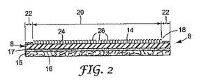
ここで図1および図2を参照すると、変換パッド8は、研磨物品4に付着する第1主面14と、バックアップパッド6の係合面12に係合する、反対側の第2主面16とを有する。第1主面14は、複数のフックタイプの締結要素26を含む。変換パッド8は、係合面12に固定されると、バックアップパッド6に対し、研磨物品4をバックアップパッド6に取り付けるために使用することができる新たな嵌合面、すなわち面14を提供する。
Referring now to FIGS. 1 and 2, the
変換パッド8は、変換パッド8の構造的完全性および耐久性を向上させるのに役立つ裏当て15を含む。裏当ては、たとえば、一層のホットメルト接着剤17で変換パッド8に接着接合される一層のバルカンファイバボードであってもよい。
The
研磨物品4は、変換パッド8の第1主面14と係合する関連嵌合面28を含む第1主面28と、第1主面の反対側の、堅木の床(図示せず)等の加工物表面を研磨するための研磨第2主面21と、を含む。研磨物品4および変換パッド8は、サイズおよび形状が実質的に同じであり、それらの外周縁部が位置合せされるように輪郭が一致することが好ましい。このように、変換パッド8は、研磨物品の、別の面に当接する加工物表面の縁に沿ってサンディングすることができる能力を妨げない。すなわち、変換パッド8の外縁と研磨物品4の外縁とを位置合せすることにより、研磨物品4は、壁等の当接面に直接隣接する領域を、壁に損傷を与えることなく有効にサンディングすることができる。
The abrasive article 4 includes a first
本発明の特色となる特徴によれば、変換パッド8の第1主面14は、内部取付領域20と周辺非取付領域22とを備えた取付システム18を含む。取付領域20は、研磨物品4を変換パッド8と取外し可能に接続する取付材24を含む。研磨物品4と変換パッド8との間の接続は、研磨物品4を変換パッド8に確実に取り付けるべきであり、かつ使用中、研磨物品4と変換パッド8とが相対移動しないようにすべきであるが、研磨物品4を比較的小さい力で変換パッド8から取り外すことができるようにすべきである。
According to a characteristic feature of the present invention, the first
図示する実施形態では、取付材24は、研磨物品4の関連嵌合面28に解放可能に係合する複数の外側に突出する締結要素26を含む。関連嵌合面28は、締結要素26に解放可能に係合し、それにより研磨物品4を変換パッド8に取り付けるループを有する、編みループ、縦編みループファブリック、縫いループファブリックまたは織りループファブリックであってもよい、ループファブリック29を含む。
In the illustrated embodiment, the
取付材24および関連嵌合面28は、ループタイプの嵌合材と嵌合するフックタイプの締結要素、複数の相互かみ合い部分を有する自己嵌合式異形押出しファスナ、またはマッシュルーム形状のファスナ要素等の相互係合要素またはファスナ、もしくは他の既知のファスナを含む種々の適当なメカニカルファスナを含んでもよい。
The mounting
締結要素26が自己嵌合式である、すなわち同一であるかまたは実質的に類似する構造を有する他の嵌合要素と相互連結して係合することができる場合、研磨物品4の関連嵌合面28には、変換パッド8の第1主面14と同じ締結要素が設けられる。締結要素26は、再締結可能である、すなわち、一旦締結要素が嵌合面と接続されても、それが同じ嵌合面または別の嵌合面と再度接続することができなくなるようにすることなく、引き離すことができることが好ましい。
The associated mating surface of the abrasive article 4 when the
適当なファスナは、種々の形態をとってもよい。1つの例示的なタイプには、米国特許第2,717,437号明細書(デメストラル(de Mestral))に記載されているフックフックファスナ、米国特許第3,009,235号明細書(デメストラル(de Mestral))に記載されているフックループファスナ、および米国特許第4,846,815号明細書(スクリップス(Scripps))にさらに記載されている頭付きステムまたはマッシュルームループファスナがある。 Suitable fasteners may take a variety of forms. One exemplary type includes the hook-hook fastener described in US Pat. No. 2,717,437 (de Mestral), US Pat. No. 3,009,235 (demestral ( de Mest)) and hooked stem or mushroom loop fasteners further described in U.S. Pat. No. 4,846,815 (Scrips).
多数の係合要素を使用する別のグループのファスナは、主に、ステムとステム先端における拡大部分すなわち頭部とを含む中実突起を有するものである。拡張部分すなわち頭部は、多種多様の形状を有することができる。通常、これらのファスナは自己嵌合式であり、頭部は、頭部間の空間より直径または断面が大きい。このタイプのファスナについて述べている例示的な特許には、たとえば米国特許第2,499,898号明細書(アンダーソン(Anderson))、米国特許第3,192,589号明細書(ピアソン(Pearson))、米国特許第3,266,113号明細書(フラナガン,Jr(Flanagan,Jr.)、米国特許第3,408,705号明細書(カイザー(Kayser)ら)および米国特許第5,097,570号明細書(ガーシェンソン(Gershenson))がある。 Another group of fasteners that use multiple engagement elements are those that have solid projections that mainly include a stem and an enlarged portion or head at the stem tip. The extension or head can have a wide variety of shapes. Typically, these fasteners are self-fitting and the head has a larger diameter or cross section than the space between the heads. Exemplary patents describing this type of fastener include, for example, U.S. Pat. No. 2,499,898 (Anderson), U.S. Pat. No. 3,192,589 (Pearson). ), U.S. Pat. No. 3,266,113 (Flanagan, Jr.), U.S. Pat. No. 3,408,705 (Kayser et al.) And U.S. Pat. No. 5,097, No. 570 (Gershenson).
米国特許第3,899,805号明細書(マクミラン(McMillan))は、頭付き中空突起を使用することについて教示している。このタイプのファスナは、上に断面積が縮小した部分または制限されたポケットがある台にかつ/またはステムの撓曲により台に嵌入する拡張部分を含む。このタイプのファスナの結合は、通常、ファスナが着座する際に単一または二重スナップと関連する。 U.S. Pat. No. 3,899,805 (McMillan) teaches the use of a headed hollow projection. This type of fastener includes an extended portion that fits into a table with a reduced cross-sectional area on top or a pocket with limited pockets and / or stem bending. This type of fastener coupling is usually associated with a single or double snap when the fastener is seated.
多数の相互にかみ合う中実突起を有する別のタイプのファスナは、米国特許第4,875,259号明細書(アペルドーン(Appeldorn))に述べられている。このタイプのファスナでは、突起の先端は拡大しておらず頭付きでもない。相互にかみ合う突起の接触面の間にもたらされる摩擦力により接合が形成される。ここでそれら接触面は、光学的に平滑な平面である。このグループにおけるファスナのさらなる例は、米国特許第5,071,363号明細書(レイレック(Reylek)ら)、米国特許第5,088,164号明細書(ウィルソン(Wilson)ら)、米国特許第5,113,555号明細書(ウィルソン(Wilson)ら)および米国特許第5,201,101号明細書(ラウザー(Rouser)ら)に見ることができる。ウェブを貫通しウェブの一方の側から他方の側までの列において互い違いになる突起に基づくファスナは、米国特許第4,581,792号明細書(スピアー(Spier))に開示されている。このファスナは、くぼみに突起を係合させて解放可能な摩擦嵌合を形成することによって機能する。 Another type of fastener having a number of interlocking solid projections is described in US Pat. No. 4,875,259 (Appeldon). In this type of fastener, the tip of the protrusion is not enlarged or headed. A bond is formed by the frictional force produced between the contact surfaces of the interdigitated protrusions. Here, these contact surfaces are optically smooth planes. Additional examples of fasteners in this group include US Pat. No. 5,071,363 (Reylek et al.), US Pat. No. 5,088,164 (Wilson et al.), US Pat. No. 5,113,555 (Wilson et al.) And US Pat. No. 5,201,101 (Rouser et al.). Fasteners based on protrusions that penetrate the web and stagger in rows from one side of the web to the other are disclosed in US Pat. No. 4,581,792 (Spier). The fastener functions by engaging a protrusion in the recess to form a releasable friction fit.
図1および図2に示す実施形態では、非取付領域22は、第2主面14の全周縁に外接する環状領域を含む。この構成により、使用者が取外し手続き中に研磨物品4の取り付けられない部分の特定の位置を見つける必要がなくなる。代りに、使用者は、変換パッド8の円周全体に沿った任意の位置で摩擦物品4を掴持することができる。
In the embodiment shown in FIGS. 1 and 2, the
しかしながら、非取付領域22は、第1主面14の縁部分を含み、使用者が、研磨物品4を掴持し、かつ研磨品4を変換パッド8の第1主面14から容易に分離することができるようにする説明した機能を提供する限り、種々の形状およびサイズを含んでもよい。
However, the
図3aおよび図3bは、非取付領域22の2つのあり得る代替構成を示す。図3aにおいて、非取付領域22は、変換パッド8の円周の長さに沿って延在する弧と、弧の両端の間に延在する線と、によって画定される半円形領域を含む。締結要素26は、取付領域20を含む面14の残りの部分に設けられる。このように配置されると、研磨物品が変換パッド8に取り付けられた時、非取付領域22に隣接して配置された研磨物品の部分は、使用者が変換パッド8から研磨物品を分離し取り外すために手で掴持し引くことができるプルタブまたはフラップを形成する。図3bでは、非取付領域22は、第1主面14のパイ形状(pie−shaped)スライスを含む。残りの取付領域20に締結要素26が設けられる。本発明の範囲内にある取付領域20および非取付領域22の他のパターンまたは構成は、当業者には明らかとなろう。
FIGS. 3 a and 3 b show two possible alternative configurations of the
非取付領域22を、複数の方法で形成してもよい。たとえば、変換パッド8の第1主面14(取付領域20および非取付領域22の両方を含む)に締結要素26が設けられる場合、締結要素26自体の構造を、関連嵌合面28に付着するそれらの能力を抑制するように、除去し、破砕し、屈曲させ、溶解し、または他の方法で変形させることにより、非取付領域22の締結要素26を変更することによって、非取付領域22を形成してもよい。
The
図4aおよび図4bに示すように、非取付領域22を、締結要素26が関連嵌合面28に付着しないように、締結要素26をシート材30で覆うことによって形成してもよい。シート材30は、たとえば、締結要素26の末端32に接着取付けされる接着面を含むシート状の重合体材料であってもよい。
As shown in FIGS. 4 a and 4 b, the
図5aおよび図5bは別の実施形態を示し、そこでは、非取付領域22は、締結要素26をエポキシ等の硬化可能な液体34でコーティングすることによって形成される。液体34は、締結要素26の周囲の開放空間を、締結要素26のフック部分の高さまで充填し、それにより、締結要素26が関連嵌合面28に付着しないようにする。
FIGS. 5a and 5b show another embodiment in which the
非取付領域22を、単純にいかなる締結要素26もなしに非取付領域22を形成することによって作成してもよい。しかしながら、この技法により、研磨物品のための支持面が平坦でなくなる可能性があり、それにより、研磨物品のサンディング性能が低下する結果となる可能性がある。このため、非取付領域22を、取付領域20と同じ高さであるように確立することが望ましい場合もあり、それにより、取付領域と非取付領域とが本質的に同一平面上にあるようになる。図6aおよび図6bに示すように、これを、非取付領域22にリップまたはうね36を設けることによって達成することができる。図示するように、リップ36は、一片の圧縮性弾性発泡体を第1主面14の非取付領域22に取り付けることによって形成される。別法として、リップ36を、変換パッド8の一部として一体的に成形してもよい。
The
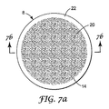
接着剤等の他の技法を使用して研磨物品4を変換パッド8に取り付けてもよい、ということが理解されよう。図7aおよび図7bに示すように、たとえば、取付領域20は接着剤を含んでもよく、非取付領域22は非接着領域を含んでもよい。適当な接着剤は、ミネソタ州セントポールの3Mカンパニー(3M Company(St.Paul,MN))から販売されているポストイット(Post−It)(登録商標)ノートブランドである。
It will be appreciated that other techniques such as adhesive may be used to attach the abrasive article 4 to the
変換パッド8の第1主面14全体が最初に接着性である場合、非取付領域22を、適当なフィルム、紙、粉末、発泡体またはインクでコーティングすることによる等、従来の処置を使用して非接着性にしてもよい。別法として、変換パッド8が、非接着性裏当てを使用し後に接着剤でコーティングされることによって形成される場合、非取付領域22を、単純に接着剤でコーティングしないことによって非接着性にしてもよい。
If the entire first
本発明のさまざまな実施形態における非取付領域22は、必ずしもではないが、研磨物品4と変換パッド8との間の取付を完全になくす、ということが理解されよう。むしろ、非取付領域22は、研磨物品4と変換パッド8との間の取付けを、使用者が非取付領域22において変換パッド8から研磨物品4を容易に分離することができるために十分な程度まで抑制するだけでよく、そのため使用者は、研磨物品4を掴持して、変換パッド8の取付領域20から研磨物品4を取り外すことができる。
It will be appreciated that the
本発明の一態様では、非取付領域22と関連嵌合面28との間に形成される接続は、取付領域22と関連嵌合面28との間に形成される接続より弱い。すなわち、研磨物品4を変換パッド8から分離するために必要な力は、取付領域20におけるよりも非取付領域22における方が弱い。取外しを容易にするために、研磨物品4は、非取付領域において変換パッド8に取り付けられていないことが好ましく、または単に緩く取り付けられており、それにより、使用者は、研磨物品4の縁部分を変換パッド8から容易に分離することができる。そして、分離された縁部分は、使用者がしっかりと掴持することができ、取付領域22を関連嵌合面28から分離する剥離力を生成する開始点としての役割を果たす。
In one aspect of the invention, the connection formed between the
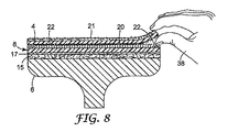
図8は、図1および図2に示す変換パッド8から研磨物品4を取り外すことを示す。図示するように、非取付領域22を含む、変換パッド8の環状円周縁部分にオーバラップする研磨物品4は、非取付領域22に取り付けられておらず、または単に緩く取り付けられており、それにより、使用者が、自身の手38を用いて研磨物品4の円周に沿った任意の箇所において研磨物品4の縁部分を掴持することができるようにする。そして、使用者は、取付領域20から研磨物品4を剥離することにより、研磨物品4を変換パッド8から完全に分離することができる。このように、取付領域22は、使用者が容易に研磨物品4を掴持し研磨物品4を変換パッド8から分離することができるようにするプルタブを提供することにより、研磨物品4の変換パッド8からの分離を容易にする。
FIG. 8 shows the removal of the abrasive article 4 from the
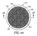
図9aおよび図9bは、変換パッド8の代りに研磨物品104に取付システム118が設けられる、本発明の別の実施形態を示す。図9aおよび図9bにおいて、図1乃至図8の特徴に機能的に類似する機能を、100だけ増分した同様の参照数字で参照する。研磨物品104の第1主面140は、内部取付領域120と、環状周縁非取付領域122と、を含む。取付領域120は、研磨物品104を変換パッド8に取外し可能に接続するための取付材124を含む。図示する実施形態では、取付材124は、ループタイプファブリック129を備える。しかしながら、取付材24および関連嵌合面28に関して上述したもののような他の取付材を使用してもよい。取付領域120は接着剤を含んでもよく、かつ非取付領域122は非接着領域を含んでもよい、ということが理解されよう。適当な接着剤は、ミネソタ州セントポールの3Mカンパニー(3M Company(St.Paul,MN))から販売されているポストイット(Post−It)(登録商標)ノートブランドである。
FIGS. 9 a and 9 b show another embodiment of the present invention in which an
非取付領域122領域は、第1主面140の全周縁にわたって延在する環状領域を含む。非取付領域122は、変換パッド8の非取付領域22で上述したような方法で、非取付領域122が変換パッドの関連嵌合面に付着するのを抑制するように、覆われ、コーティングされ、または他の方法で変更された取付材124を含んでもよい。別法として、非取付領域122を、単純に取付材124なしに非取付領域122を形成することにより、または研磨物品104の第1主面140の選択された1つまたは複数の領域から取付領域124を除去することにより、作成してもよい。
The
上述した発明の概念から逸脱することなく、さまざまな変形および変更を行ってもよい、ということが当業者には明らかとなろう。たとえば、研磨物品および変換パッドは、正方形、三角形、矩形、長円形、五角形、六角形、八角形等を含む種々のサイズおよび形状であってもよい。さらに、変換パッドに設けられるように上述した取付システムの任意のものを、研磨物品に設けてもよい、ということが理解されよう。すなわち、取付システム18および関連嵌合面28の構成を反対にしてもよい。このため、本発明の範囲は、この出願に記載されている構造に限定されるべきではなく、特許請求の範囲およびそれら構造の等価物の文言によって記載されている構造によってのみ限定されるべきである。
It will be apparent to those skilled in the art that various modifications and variations can be made without departing from the inventive concepts described above. For example, the abrasive article and conversion pad may be of various sizes and shapes including squares, triangles, rectangles, ovals, pentagons, hexagons, octagons, and the like. Further, it will be appreciated that any of the mounting systems described above as provided on the conversion pad may be provided on the abrasive article. That is, the configuration of the
Claims (40)
Applications Claiming Priority (2)
| Application Number | Priority Date | Filing Date | Title |
|---|---|---|---|
| US10/821,071 US8002612B2 (en) | 2004-04-08 | 2004-04-08 | Attachment system for a sanding tool |
| PCT/US2005/008574 WO2005102607A1 (en) | 2004-04-08 | 2005-03-14 | Attachment system for a sanding tool |
Publications (2)
| Publication Number | Publication Date |
|---|---|
| JP2007532329A true JP2007532329A (en) | 2007-11-15 |
| JP2007532329A5 JP2007532329A5 (en) | 2008-03-21 |
Family
ID=34963602
Family Applications (1)
| Application Number | Title | Priority Date | Filing Date |
|---|---|---|---|
| JP2007507325A Withdrawn JP2007532329A (en) | 2004-04-08 | 2005-03-14 | Mounting system for sanding tools |
Country Status (6)
| Country | Link |
|---|---|
| US (1) | US8002612B2 (en) |
| EP (1) | EP1742769A1 (en) |
| JP (1) | JP2007532329A (en) |
| CN (1) | CN1964818A (en) |
| CA (1) | CA2563171A1 (en) |
| WO (1) | WO2005102607A1 (en) |
Families Citing this family (33)
| Publication number | Priority date | Publication date | Assignee | Title |
|---|---|---|---|---|
| US7458883B2 (en) * | 2006-01-31 | 2008-12-02 | B A Werk Industries Ltd. | Apparatus for abrading a surface |
| US7731573B2 (en) | 2008-01-30 | 2010-06-08 | 3M Innovative Properties Company | Method, system, and apparatus for modifying surfaces |
| US20090191376A1 (en) | 2008-01-30 | 2009-07-30 | 3M Innovative Properties Company | Method, apparatus, and system using adapter assembly for modifying surfaces |
| US7892074B2 (en) * | 2008-01-30 | 2011-02-22 | 3M Innovative Properties Company | Surface modifying tool adapter using a plurality of surface modifying article inserts for use in a surface modifying system |
| US20100009606A1 (en) * | 2008-07-10 | 2010-01-14 | 3M Innovative Properties Company | Conversion assemblage adaptable for use in combination with a surface modifying apparatus and method thereof |
| US20100009607A1 (en) * | 2008-07-10 | 2010-01-14 | 3M Innovative Properties Company | Conversion assemblage adaptable for use in combination with a surface modifying apparatus and method thereof |
| US8469775B2 (en) | 2008-07-10 | 2013-06-25 | 3M Innovative Properties Company | Conversion assemblage adaptable for use in combination with a surface modifying apparatus and method thereof |
| CN102481684B (en) * | 2009-08-28 | 2014-12-03 | 3M创新有限公司 | Abrasive article having a line of weakness |
| DE102010028123A1 (en) * | 2010-04-22 | 2011-10-27 | Robert Bosch Gmbh | Sharpening plate device for hand-guided grinder, has sand paper arranged on bottom side of sharpening plate, and hook-and-loop fastener whose sections are extended to sharpening plate over partial flange of bottom side of sharpening plate |
| US20110300784A1 (en) * | 2010-06-04 | 2011-12-08 | Tchakarov Tchavdar V | Flexible and interchangeable multi-head floor polishing disk assembly |
| WO2013102206A1 (en) * | 2011-12-31 | 2013-07-04 | Saint-Gobain Abrasives, Inc. | Abrasive article having a non-uniform distribution of openings |
| DE102012013043B4 (en) * | 2012-06-29 | 2014-09-11 | Emag Holding Gmbh | Grinding wheel and machine tool |
| DE102013203116A1 (en) * | 2013-02-26 | 2014-08-28 | Robert Bosch Gmbh | Abrasive device |
| US20150056899A1 (en) * | 2013-08-23 | 2015-02-26 | Jose De Souza | Interchangeable abrasive glove |
| US9072343B1 (en) | 2014-01-02 | 2015-07-07 | John W. Ogilvie | Multigrip touch closure fasteners |
| JP6452295B2 (en) * | 2014-03-19 | 2019-01-16 | スリーエム イノベイティブ プロパティズ カンパニー | Polishing pad and glass substrate polishing method |
| USD795666S1 (en) | 2014-06-06 | 2017-08-29 | Diamond Tool Supply, Inc. | Polishing pad |
| US10414012B2 (en) | 2017-01-13 | 2019-09-17 | Husqvarna Construction Products North America, Inc. | Grinding pad apparatus |
| US10246885B2 (en) | 2014-09-18 | 2019-04-02 | Husqvarna Construction Products North America, Inc. | Grouting pan assembly with reinforcement ring |
| US9580916B2 (en) | 2014-09-18 | 2017-02-28 | Diamond Tool Supply, Inc. | Method for finishing a composite surface and a grounting pan for finishing a composite surface |
| US11351654B2 (en) * | 2014-11-26 | 2022-06-07 | 3M Innovative Properties Company | Abrasive articles, assemblies, and methods with gripping material |
| CA3102523C (en) | 2015-09-24 | 2023-12-12 | Husqvarna Ab | Polishing or grinding pad assembly |
| NL2015861B1 (en) * | 2015-11-26 | 2017-06-13 | James Broussard Quintin | Backing pad for a sander, such as an eccentric sander. |
| CN105500186A (en) * | 2016-01-21 | 2016-04-20 | 苏州新美光纳米科技有限公司 | Polishing pad for wafer polishing and self-absorption method thereof |
| CA2959779C (en) | 2016-03-04 | 2019-06-11 | The Libman Company | Scissor-style toilet brush |
| USD800456S1 (en) | 2016-03-04 | 2017-10-24 | The Libman Company | Brush handle |
| USD854902S1 (en) | 2016-09-23 | 2019-07-30 | Husqvarna Construction Products North America, Inc. | Polishing or grinding pad |
| DE102016222043A1 (en) * | 2016-11-10 | 2018-02-22 | Bayerische Motoren Werke Aktiengesellschaft | sharpener |
| USD927952S1 (en) * | 2017-08-30 | 2021-08-17 | Husqvarna Ab | Polishing or grinding pad assembly with abrasive disk, spacer, reinforcement and pad |
| AU201810919S (en) | 2017-08-30 | 2018-04-13 | Husqvarna Construction Products North America | Polishing or grinding pad assembly with abrasive discs reinforcement and pad |
| USD958626S1 (en) * | 2017-08-30 | 2022-07-26 | Husqvarna Ab | Polishing or grinding pad assembly with abrasive disks, reinforcement and pad |
| US11565370B2 (en) * | 2017-12-20 | 2023-01-31 | Fabrica Machinale S.R.L. | Method and apparatus for carrying out the replacement of an abrasive element in a machine for working surfaces |
| US10710214B2 (en) * | 2018-01-11 | 2020-07-14 | Husqvarna Ab | Polishing or grinding pad with multilayer reinforcement |
Family Cites Families (30)
| Publication number | Priority date | Publication date | Assignee | Title |
|---|---|---|---|---|
| US2499898A (en) | 1946-12-23 | 1950-03-07 | Albert F Anderson | Clasp |
| BE514797A (en) | 1951-10-22 | 1900-01-01 | ||
| US3009235A (en) | 1957-10-02 | 1961-11-21 | Internat Velcro Company | Separable fastening device |
| US3192589A (en) | 1960-07-18 | 1965-07-06 | Raymond C Pearson | Separable fastener |
| US3266113A (en) | 1963-10-07 | 1966-08-16 | Minnesota Mining & Mfg | Interreacting articles |
| US3408705A (en) | 1966-07-07 | 1968-11-05 | Minnesota Mining & Mfg | Fastener articles |
| US3527001A (en) * | 1967-06-01 | 1970-09-08 | Minnesota Mining & Mfg | Holder for abrasive product |
| US3522681A (en) * | 1968-12-18 | 1970-08-04 | Gerald Lampert | Rubbing apparatus |
| US3899805A (en) | 1973-07-13 | 1975-08-19 | Dow Chemical Co | Indented sheet |
| US3875703A (en) * | 1973-12-26 | 1975-04-08 | Joseph V Clemente | Flexible sanding disc unit |
| EP0112405B1 (en) | 1982-12-24 | 1987-09-09 | Hans J. Fabritius | Attaching element to be employed in grinding and polishing machines |
| US4581792A (en) | 1983-02-18 | 1986-04-15 | Clements Industries Incorporated | Separable fastener |
| US4617767A (en) * | 1985-01-14 | 1986-10-21 | Ali Frank F | Sanding, buffing and polishing tool and parts thereof |
| US4875259A (en) | 1986-09-08 | 1989-10-24 | Minnesota Mining And Manufacturing Company | Intermeshable article |
| US5113555A (en) | 1986-09-08 | 1992-05-19 | Minnesota Mining And Manufacturing Company | Container with intermeshable closure members |
| US5088164A (en) | 1986-09-08 | 1992-02-18 | Minnesota Mining And Manufacturing Company | Container with intermeshable closure members |
| US4846815A (en) | 1987-01-26 | 1989-07-11 | The Procter & Gamble Company | Disposable diaper having an improved fastening device |
| US5071363A (en) | 1990-04-18 | 1991-12-10 | Minnesota Mining And Manufacturing Company | Miniature multiple conductor electrical connector |
| US5097570A (en) | 1991-01-23 | 1992-03-24 | Bruce Gershenson | Fastening system |
| US5540970A (en) * | 1991-05-03 | 1996-07-30 | Velcro Industries B.V. | Die cut mold-in |
| US5201785A (en) * | 1991-05-10 | 1993-04-13 | Minnesota Mining & Manufacturing Company | Disc-holder assembly |
| US5201101A (en) | 1992-04-28 | 1993-04-13 | Minnesota Mining And Manufacturing Company | Method of attaching articles and a pair of articles fastened by the method |
| DE4339110A1 (en) * | 1993-11-16 | 1995-05-18 | Koltec Ag | Holder for fleece polishing discs |
| AU692828B2 (en) | 1994-01-13 | 1998-06-18 | Minnesota Mining And Manufacturing Company | Abrasive article, method of making same, and abrading apparatus |
| TW317223U (en) * | 1994-01-13 | 1997-10-01 | Minnesota Mining & Mfg | Abrasive article |
| US5807161A (en) * | 1996-03-15 | 1998-09-15 | Minnesota Mining And Manufacturing Company | Reversible back-up pad |
| US5731056A (en) * | 1996-06-11 | 1998-03-24 | Mcdonnell Douglas Helicopter Company | Rigid structure attachment using hook and loop fasteners |
| DE69805150T2 (en) * | 1997-12-03 | 2002-12-12 | Ykk Corp | Tool holder for portable oscillating grinder |
| US6210389B1 (en) * | 1998-09-17 | 2001-04-03 | Kimberly-Clark Worldwide, Inc. | Fastener system with a lift region |
| US6394887B1 (en) | 1999-04-19 | 2002-05-28 | Stillman Eugene Edinger | Apparatus for use with automated abrading equipment |
-
2004
- 2004-04-08 US US10/821,071 patent/US8002612B2/en not_active Expired - Fee Related
-
2005
- 2005-03-14 CN CNA2005800189065A patent/CN1964818A/en active Pending
- 2005-03-14 WO PCT/US2005/008574 patent/WO2005102607A1/en active Application Filing
- 2005-03-14 JP JP2007507325A patent/JP2007532329A/en not_active Withdrawn
- 2005-03-14 EP EP05729393A patent/EP1742769A1/en not_active Withdrawn
- 2005-03-14 CA CA002563171A patent/CA2563171A1/en not_active Abandoned
Also Published As
| Publication number | Publication date |
|---|---|
| US8002612B2 (en) | 2011-08-23 |
| EP1742769A1 (en) | 2007-01-17 |
| CN1964818A (en) | 2007-05-16 |
| WO2005102607A1 (en) | 2005-11-03 |
| US20050227600A1 (en) | 2005-10-13 |
| CA2563171A1 (en) | 2005-11-03 |
Similar Documents
| Publication | Publication Date | Title |
|---|---|---|
| JP2007532329A (en) | Mounting system for sanding tools | |
| US5170595A (en) | Pull tab for velcro backed marble grinding pad and method for removal | |
| KR100329308B1 (en) | Improved Sanding Disc | |
| CA2045381C (en) | Lamellar end grinding tool | |
| CA2713709C (en) | Surface modifying tool adapter using a plurality of surface modifying article inserts for use in a surface modifying system | |
| US6234886B1 (en) | Multiple abrasive assembly and method | |
| US4263755A (en) | Abrasive product | |
| JP2001526593A (en) | Composite polishing assembly and method | |
| JP2001522731A (en) | Backup pad for abrasive products and method of use | |
| EP2262613B1 (en) | Method, apparatus, and system using adapter assembly for modifying surfaces | |
| TW422759B (en) | Improved grinding system | |
| US6186878B1 (en) | Apparatus relating to sanders | |
| JP2002307315A (en) | Fixing device for abrasive cloth and paper | |
| AU2005336407B2 (en) | Abrasive body | |
| JP5407016B2 (en) | Brush pad with hook-and-loop fastener | |
| JPH0432214Y2 (en) | ||
| JP3194035U (en) | Wall fasteners | |
| JPS6232774Y2 (en) | ||
| JP3098043U (en) | Polishing tool that can be used on both sides | |
| EP1607181B1 (en) | Abrasive body | |
| CA1112050A (en) | Flexible abrasive sheet and holder | |
| JP2000093371A (en) | Pad holder for electric floor polisher | |
| EP1698434A1 (en) | Geinder | |
| JP2002178269A (en) | Polishing wheel | |
| JP2006187818A (en) | Buff |
Legal Events
| Date | Code | Title | Description |
|---|---|---|---|
| A521 | Written amendment |
Free format text: JAPANESE INTERMEDIATE CODE: A523 Effective date: 20080129 |
|
| A621 | Written request for application examination |
Free format text: JAPANESE INTERMEDIATE CODE: A621 Effective date: 20080129 |
|
| A761 | Written withdrawal of application |
Free format text: JAPANESE INTERMEDIATE CODE: A761 Effective date: 20080718 |