JP2007531934A - Discrimination of important areas in images - Google Patents
Discrimination of important areas in images Download PDFInfo
- Publication number
- JP2007531934A JP2007531934A JP2007505140A JP2007505140A JP2007531934A JP 2007531934 A JP2007531934 A JP 2007531934A JP 2007505140 A JP2007505140 A JP 2007505140A JP 2007505140 A JP2007505140 A JP 2007505140A JP 2007531934 A JP2007531934 A JP 2007531934A
- Authority
- JP
- Japan
- Prior art keywords
- image
- original image
- display device
- controller
- user input
- Prior art date
- Legal status (The legal status is an assumption and is not a legal conclusion. Google has not performed a legal analysis and makes no representation as to the accuracy of the status listed.)
- Pending
Links
Images


Classifications
-
- G—PHYSICS
- G06—COMPUTING; CALCULATING OR COUNTING
- G06T—IMAGE DATA PROCESSING OR GENERATION, IN GENERAL
- G06T11/00—2D [Two Dimensional] image generation
- G06T11/60—Editing figures and text; Combining figures or text
-
- H—ELECTRICITY
- H04—ELECTRIC COMMUNICATION TECHNIQUE
- H04N—PICTORIAL COMMUNICATION, e.g. TELEVISION
- H04N23/00—Cameras or camera modules comprising electronic image sensors; Control thereof
- H04N23/60—Control of cameras or camera modules
- H04N23/63—Control of cameras or camera modules by using electronic viewfinders
- H04N23/633—Control of cameras or camera modules by using electronic viewfinders for displaying additional information relating to control or operation of the camera
- H04N23/635—Region indicators; Field of view indicators
-
- H—ELECTRICITY
- H04—ELECTRIC COMMUNICATION TECHNIQUE
- H04N—PICTORIAL COMMUNICATION, e.g. TELEVISION
- H04N23/00—Cameras or camera modules comprising electronic image sensors; Control thereof
- H04N23/80—Camera processing pipelines; Components thereof
-
- H—ELECTRICITY
- H04—ELECTRIC COMMUNICATION TECHNIQUE
- H04N—PICTORIAL COMMUNICATION, e.g. TELEVISION
- H04N2101/00—Still video cameras
Abstract
表示装置および表示装置を動作させるための方法が提供される。表示装置は原画像のソースおよびディスプレイを有している。ユーザー入力システムは、ユーザー入力動作に反応して非方向性信号を生成するよう適応されている。コントローラが設けられていて、該非方向性信号を検出し、原画像の諸部分の集合のうちの異なる一つを逐次指定するよう適応されている。コントローラはさらに、ディスプレイをして、原画像の現在指定されている部分を示す部分評価画像を呈示させ、現在指定されている部分に基づいて原画像内の重要領域を決定するよう適応されている。原画像の諸部分の集合に含まれる部分のうちの少なくとも一つは、原画像と中心が同じではない。
A display device and a method for operating the display device are provided. The display device has an original image source and a display. The user input system is adapted to generate a non-directional signal in response to a user input action. A controller is provided and is adapted to detect the non-directional signal and sequentially designate a different one of the set of portions of the original image. The controller is further adapted to cause the display to present a partial evaluation image showing the currently designated portion of the original image and to determine an important region within the original image based on the currently designated portion. . At least one of the parts included in the set of parts of the original image is not the same as the center of the original image.
Description
本発明は、原画像における重要な領域を判別する画像処理の方法およびシステムに関する。 The present invention relates to an image processing method and system for discriminating important regions in an original image.
デジタル画像はインフォイメージング(info-imaging)のますます人気のある形態となりつつある。この人気の一つの理由は、そのようなデジタル画像は取り込み後にユーザーが操作し、編集し、変更し、改善することが容易なことである。たとえば、ユーザーはしばしば、デジタル画像の見え方を向上させるために、米国ニューヨーク州ロチェスターのイーストマン・コダック社によって販売されているコダック・ピクチャーCDというソフトウェアにて提供されているトリミングやズームのツールといったような手動のデジタル画像処理および編集ツールを利用する。こうした画像編集ツールによって、ユーザーは画像中の重要な要素を強調するために画像の内容に限界を付けることができる。画像が取り込まれたのちにユーザーが重要であると考える画像部分に有用に適用されるものには、他の画像編集、分別その他のツールもある。しかし、取り込み後段階では、典型的には写真家がそのようなツールを使って重要領域指定をするのは、選択された画像についてのみである。 Digital images are becoming an increasingly popular form of info-imaging. One reason for this popularity is that such digital images are easy to manipulate, edit, change and improve after the capture by the user. For example, users often use cropping and zooming tools provided by the Kodak Picture CD software sold by Eastman Kodak Company of Rochester, New York to improve the appearance of digital images. Utilize manual digital image processing and editing tools such as: These image editing tools allow users to limit the content of the image to emphasize important elements in the image. There are other image editing, sorting and other tools that can be usefully applied to image parts that the user considers important after the image is captured. However, at the post-capture stage, a photographer typically designates an important area using such a tool only for the selected image.
関心領域判別を、画像が取り込まれた時点における画像に関連付けることがしばしば有用である。画像取り込みの時点または使用中にそのような関連付けを構築することで、画像が、少なくとも部分的には重要性領域情報に基づいて決定される仕方で処理され、保存され、分別され、および/または共有されることが可能になる。さらに、そのような指定が取り込みの際に単純な仕方でできるという限りにおいて、写真家がより多くの画像についてそのような指定をし、そのような指定がより正確になる可能性が高まる。さらに、画像を撮影し、あるいは他の仕方で取得し、すぐ遠方の受信者に送信することを可能にするデジタルカメラおよびその他の表示装置(display device)の使用が増えたことで、多くのユーザーは、画像中で重要なものを手動で指定するための、迅速かつ効率的に実行できる簡単かつ効率的な手段をも望んでいる。 Often it is useful to relate region of interest discrimination to the image at the time the image was captured. By constructing such associations at the time of image capture or during use, the images are processed, stored, sorted, and / or in a manner determined at least in part based on importance region information. It can be shared. Furthermore, to the extent that such a designation can be made in a simple manner upon capture, it is likely that the photographer will make such a designation for more images and such a designation will be more accurate. In addition, the increased use of digital cameras and other display devices that allow images to be taken or otherwise acquired and sent to a distant recipient can help many users. Also wants a simple and efficient means that can be quickly and efficiently performed to manually specify what is important in the image.
自動的および半自動的画像処理および編集アルゴリズムが知られている。これらは、ユーザー入力をほとんど必要とせずにデジタル画像の見え方を向上させるために適用できる。これらの自動的および半自動的画像処理アルゴリズムは画像の内容を解析し、ユーザーが画像の重要な要素であると見出しそうなものについてのさまざまな想定を適用する。 Automatic and semi-automatic image processing and editing algorithms are known. These can be applied to improve the appearance of a digital image with little need for user input. These automatic and semi-automatic image processing algorithms analyze the content of the image and apply various assumptions about what the user is likely to find as an important element of the image.
自動アルゴリズムの第一の例においては、既知の肌色に近い色をもつ大きな楕円形の(oval shaped)オブジェクトがユーザーにとって重要であると仮定することができる。たとえばその大きな楕円の顔型のオブジェクトが画像の中心付近に位置しているときには想定される重要性の度合いを上げることができる。たとえば、1998年12月31日にLuo et al.によって出願された“Method For Automatic Determination of Main Subjects in Photographic Images”と題する、本出願人に譲渡された米国特許第6,282,317号を参照。他のアルゴリズムは、重要性が高いと考えられる画像の要素を同定するために、デジタル画像をなすデジタルデータの周波数(frequency)解析を使う。そのようなアルゴリズムは、撮影された画像の視覚的要素の解析に基づいて、画像中で重要なものについての想定をする。たとえば、1998年10月22日にErkkilea et al.によって出願された“Determining Portions of a Digital Image Which are In Focus”と題する、本出願人に譲渡された米国特許出願第09/176,805号を参照。 In a first example of an automatic algorithm, it can be assumed that a large oval shaped object with a color close to a known skin color is important to the user. For example, when the large elliptical face-shaped object is located near the center of the image, the degree of importance assumed can be increased. See, for example, US Pat. No. 6,282,317 assigned to the present applicant entitled “Method For Automatic Determination of Main Subjects in Photographic Images” filed by Luo et al. Other algorithms use a frequency analysis of the digital data that makes up the digital image to identify the elements of the image that are considered important. Such an algorithm makes assumptions about what is important in the image based on an analysis of the visual elements of the captured image. See, for example, US patent application Ser. No. 09 / 176,805, assigned to the present applicant, entitled “Determining Portions of a Digital Image Which are In Focus” filed by Erkkilea et al.
自動的システムのさらにもう一つの例が、2002年11月25日にMiller et al.によって出願された“Digital Imaging System With Eye Monitoring”と題する、本出願人に譲渡された米国特許出願第10/303,978号において記載されている。この出願は、画像撮影シーケンスの間に視線方向情報を含む目の情報を保存し、その目の情報を該画像撮影シーケンスの間に撮影された画像と関連付ける、目モニタリングシステムを有する画像撮影システムを記載している。ある種の実施形態では、コンテキスト情報も画像に関連付けられる。そこで記載されている目モニタリングシステムはその意図された目的のために有用であり、広範な応用を有する。しかし、消費者によっては目モニタリングシステムを使わないことを好む。 Yet another example of an automatic system is US Pat. Appl. No. 10 / assigned to the present applicant entitled “Digital Imaging System With Eye Monitoring” filed by Miller et al. No. 303,978. This application relates to an image capture system having an eye monitoring system that stores eye information including line-of-sight information during an image capture sequence and associates the eye information with images captured during the image capture sequence. It is described. In certain embodiments, context information is also associated with the image. The eye monitoring system described therein is useful for its intended purpose and has a wide range of applications. However, some consumers prefer not to use an eye monitoring system.
自動システムのさらなる例が、2002年12月20日にFredlundによって出願された“Imaging Method and System For Determining An Area Importance In An Archival Image”と題する、本出願人に譲渡された米国特許出願第10/324,489号に記載されている。この出願では、諸評価画像および原画像を取得するよう動作できる画像ソースを有する画像システムが提供されている。コントローラが画像ソースをして、一組の評価画像と原画像とを取得させる。信号プロセッサが諸評価画像と原画像とを比較して、撮影された画像すべてに共通する原画像の部分を同定する。信号プロセッサは、その共通部分に対応する原画像の部分を同定する重要領域データを保存し、その重要領域データを原画像に関連付ける。 A further example of an automated system is a U.S. patent application assigned to the present applicant entitled “Imaging Method and System For Determining An Area Importance In An Archival Image” filed by Fredlund on Dec. 20, 2002. No. 324,489. In this application, an image system is provided having an image source operable to obtain evaluation images and an original image. The controller acts as an image source and acquires a set of evaluation images and original images. A signal processor compares the evaluation images and the original image to identify portions of the original image that are common to all captured images. The signal processor stores important region data that identifies the portion of the original image that corresponds to the common portion and associates the important region data with the original image.
2001年7月17日にParulski et al.によって出願された“Image Revising Camera and Method”と題する、本出願人に譲渡された米国特許第6,516,154号も自動的方法を記載している。そこではカメラが原画像をメモリに保存し、画像を解析して複数のパラメータを決定する。そのパラメータが複数の編集提案のうちの一つまたは複数にマッチングされ、提案集合が定義される。潜在的な提案集合の一つは、最終的なプリントに組み込まれる、原画像の有効領域における変化を含む。このカメラでは、有効領域における変化がカメラ操作者に提案され、操作者が今度は提案された変化を選択するか拒否するかできる。 US Pat. No. 6,516,154, assigned to the present applicant, entitled “Image Revising Camera and Method” filed by Parulski et al. On July 17, 2001, also describes an automatic method. There, the camera stores the original image in memory and analyzes the image to determine a plurality of parameters. The parameter is matched with one or more of a plurality of editing proposals to define a proposal set. One potential proposal set includes changes in the effective area of the original image that are incorporated into the final print. With this camera, changes in the effective area are proposed to the camera operator, who can now select or reject the proposed change.
そのような自動アルゴリズムはしばしば非常に有用であるものの、ユーザーによっては画像の重要領域を手動で指定するほうを好む。したがって、さまざまなカメラは、重要情報を含めるよう画像に限界を付けることを意図するユーザーに構図上の提案を提供する。 While such automatic algorithms are often very useful, some users prefer to manually specify important areas of the image. Therefore, various cameras provide compositional suggestions to users who intend to limit the image to include important information.
たとえば、1995年11月30日にMoghadam et al.によって出願された“Camera that records and Active Image Area Identifier”と題する米国特許第5,706,049号が記載するカメラは、オブジェクトの画像を撮影するための画像受容器と、画像受容器にオブジェクトからの像光を向けるための光学部と、見えている像における有効なホットスポット領域を指定するためのタイルパターンをもった、撮影に先立ってオブジェクトを見るためのファインダーとを含んでいる。ファインダーのタイルパターンは、オブジェクトの像と一緒にファインダーを通して見える複数の個別タイル領域から構成される。このカメラはさらに、一つまたは複数の個別タイル領域および画像の有効領域を指定する手段と、全有効領域の位置を当該カメラの外部にある作動装置にとってアクセス可能なメモリ位置に記録する手段とを含んでいる。この'049特許が記載する一つのデジタルカメラ実施例は、パターンメモリに保存されるべき特定のパターンを選択するためのタイルパターン選択スイッチまたは保存されているタイル領域パターンの一つまたは複数を選択的に逐次ハイライトしていって所望の有効領域がハイライトされるようにするためのタイルエリア指定スイッチのいずれかとして動作するサムホイールスイッチを有している。ホットスポット選択スイッチは、指定されたホットスポット領域の一つを選択するよう従事させられる。このように、この'049特許は、撮影された原画像のうちホットスポットの機能を実行するために使用できる領域を指定するために使われる。これは、表示装置、プレゼンテーションシステムあるいはHTMLブラウズシステムの統合と統合されることができる。 For example, a camera described in US Pat. No. 5,706,049 entitled “Camera that records and Active Image Area Identifier” filed by Moghadam et al. On Nov. 30, 1995 is an image receiver for taking an image of an object. To view the object prior to shooting, with a container, an optic for directing the image light from the object to the image receiver, and a tile pattern to specify the effective hot spot area in the visible image Includes a viewfinder. The tile pattern of the viewfinder is composed of a plurality of individual tile areas that can be seen through the viewfinder together with the object image. The camera further includes means for designating one or more individual tile areas and an effective area of the image, and means for recording the position of all effective areas in a memory location accessible to an actuator external to the camera. Contains. One digital camera embodiment described in this' 049 patent selectively selects one or more of tile pattern selection switches or stored tile area patterns for selecting a particular pattern to be stored in a pattern memory. And a thumbwheel switch that operates as one of tile area designating switches for sequentially highlighting the desired effective area. The hot spot selection switch is engaged to select one of the designated hot spot areas. As described above, the '049 patent is used to designate an area of a photographed original image that can be used for executing a hot spot function. This can be integrated with integration of display devices, presentation systems or HTML browsing systems.
手動システムのもう一つの例では、Petruchik et al.によって出願された“Pre-processing Image Editing”と題する、本出願人に譲渡された米国特許第5,619,738号は、電子ディスプレイを含むフィルムカメラを記載している。電子ディスプレイは、電子的に表示される画像の枠を決め、編集するための可動マーカーを呈示するドライバを具備している。マーカーの電子的な操作によって、画像のズームおよびトリミング、さらには画像フォーマットおよび横方向または縦方向記録の変更が提供される。編集データを、フィルム上で露光されたシーン画像に対して所定の位置に記録するコントロールもある。カメラは、それぞれが所定の大きさおよび縦横比をもつプリントフォーマットの所定の集合からプリントフォーマットを選択するための入力と、フレームフォーマットをプリントフォーマットの選択と一貫するものに限定するコントロールとを含んでいる。多様なコントロールおよびユーザー入力が、画像を選択し、形成するプロセスを容易にする。これらのコントロールにより、カメラユーザーは編集において大いに柔軟性を有することができる。 In another example of a manual system, assigned US Pat. No. 5,619,738 entitled “Pre-processing Image Editing” filed by Petruchik et al. Describes a film camera including an electronic display. ing. The electronic display includes a driver that presents a movable marker for determining and editing a frame of an electronically displayed image. Electronic manipulation of the markers provides zooming and cropping of the image, as well as changes to the image format and lateral or longitudinal recording. There is also a control for recording the edit data at a predetermined position with respect to the scene image exposed on the film. The camera includes inputs for selecting a print format from a predetermined set of print formats, each having a predetermined size and aspect ratio, and controls that limit the frame format to be consistent with the print format selection. Yes. A variety of controls and user inputs facilitate the process of selecting and forming images. These controls allow camera users great flexibility in editing.
同様に、1997年4月14日にSquilla et al.によって出願された“Photographic System With Selected Area Image Authentication”と題する、本出願人に譲渡された米国特許第5,898,779号は、画像を認証するための公開鍵暗号化システムを記載している。この暗号化システムは、それぞれがオブジェクトの画像とともに見える少なくとも一つの個別領域からなる一つまたは複数のパターンを生成する手段と、認証のために好適な画像の有効領域として少なくとも一つの個別領域を指定する手段と、該有効領域を同定する位置データを生成する手段とを有している。一つの形態では、単一のグリッドパターンが使用できる。そこではタイル領域指定スイッチが使用されて、該タイル領域を巡回してタイル領域を一つずつハイライトしてユーザーカスタマイズ可能なタイルパターンを形成する。タイルパターンは、個別タイル領域を定義するいくつかの交差する線からなり、該個別タイル領域の一つまたは複数が、画像をセキュリティで保護する目的のための有効領域として指定されうる。どのタイル領域が有効領域となるべきかを決定する過程において、一つまたは複数のタイル領域が考慮のためにハイライトされる。あるいはまた、タイルパターン選択スイッチを使って、使用されるべき領域を示す事前形成されたハイライト領域を有する事前形成された特定のタイルパターンを選択してもよい。ハイライトされたタイル領域の特定の配列すなわち事前形成されたタイルパターンを指定するために、セキュリティサービススイッチが使われる。 Similarly, assigned US Pat. No. 5,898,779 entitled “Photographic System With Selected Area Image Authentication” filed by Squilla et al. A public key encryption system is described. This encryption system specifies a means for generating one or more patterns each consisting of at least one individual area visible with an object image, and designates at least one individual area as a valid image area suitable for authentication. And means for generating position data for identifying the effective area. In one form, a single grid pattern can be used. There, a tile area designation switch is used, and the tile area is highlighted and tile areas are highlighted one by one to form a user-customizable tile pattern. A tile pattern consists of a number of intersecting lines that define individual tile areas, and one or more of the individual tile areas can be designated as effective areas for the purpose of securing an image. In the process of determining which tile area should be the effective area, one or more tile areas are highlighted for consideration. Alternatively, a tile pattern selection switch may be used to select a particular preformed tile pattern having a preformed highlight area that indicates the area to be used. A security service switch is used to specify a particular array of highlighted tile areas, ie a pre-formed tile pattern.
手動システムのさらにもう一つの例では、2002年11月12日にBrostによって出願された、“User Interface for Controlling Cropping In An Electronic Camera”と題する、本出願人に譲渡された米国特許出願第10/292,235号は、画像を撮影してその撮影された画像に基づいて光像を呈示するカメラシステムを記載している。カメラにはトリミング器が配置されており、複数の設定の間で切り換え可能になっている。各設定は異なる長方形断面の窓をファインダー内に有している。トリミングコントローラは撮影ユニットとトリミング器とに動作的に接続されている。トリミングコントロールは、本体外部にアクセス可能なトリミング入力要素を有している。トリミング入力要素は、設定を変更するために第一および第二の対向するトリミングコントロール位置の間で移動可能である。トリミングコントロール位置は、撮影ユニットの光学軸に垂直なトリミングコントロール軸を定義する。このアプローチは、画像のトリミングで使う境界を調整できるようにする単純化された制御構造を提供し、それぞれがシーン画像を中心とする怒濤のようなトリミング画像のうちから選択をするための有用かつ商業的見込みのある方法を提供する。 Yet another example of a manual system is US Pat. Appl. No. 10 / assigned to the present applicant entitled “User Interface for Controlling Cropping In An Electronic Camera” filed Nov. 12, 2002 by Brost. No. 292,235 describes a camera system that captures an image and presents a light image based on the captured image. The camera has a trimming device that can be switched between a plurality of settings. Each setting has a window with a different rectangular cross section in the viewfinder. The trimming controller is operatively connected to the photographing unit and the trimming device. The trimming control has a trimming input element accessible outside the main body. The trimming input element is movable between first and second opposing trimming control positions to change settings. The trimming control position defines a trimming control axis perpendicular to the optical axis of the photographing unit. This approach provides a simplified control structure that allows you to adjust the boundaries used for image cropping, each of which is useful for selecting among angry cropped images centered on the scene image. Provide a commercially viable method.
この種のもう一つの例では、新写真システム(Advanced Photographic System)諸規格に準拠するカメラは典型的には、高精細度テレビの縦横比に対応する縦横比をもつ第一のフォーマットを使って画像を撮影でき、ユーザーが信号をフィルム上に記録できるようにしているが、これは撮影された画像から作成されるプリントが高精細度フォーマットで、いわゆる古典フォーマットで、あるいはいわゆるパノラマフォーマットで表現されることを示している。古典フォーマットかパノラマフォーマットが選択されているときには、DPE担当者は、それぞれ高精細度画像に合わせてセンタリングされており、それぞれ異なる縦横比を有する撮影された画像のトリミングされた部分を使用する。 In another example of this type, cameras that conform to the Advanced Photographic System standards typically use the first format with an aspect ratio that corresponds to the aspect ratio of high-definition television. The image can be taken and the user can record the signal on film, but this is a print created from the taken image in high definition format, so-called classical format or so-called panoramic format. Which indicates that. When the classic or panoramic format is selected, the DPE personnel are centered for high-definition images and use cropped portions of the captured images, each with a different aspect ratio.
したがって、必要とされているのは、デジタルカメラもしくはハイブリッドカメラ、携帯情報端末(Personal Digital Assistant)または電子画像を呈示できる他の任意のシステムのような表示装置であって、撮影された画像内の重要領域の迅速かつ単純化された手動指定を可能にし、それにより画像のどの部分が指定されたかが容易に決定できるような出力を提供するようにするユーザーインターフェースシステムをも有しているものである。 Therefore, what is needed is a display device, such as a digital or hybrid camera, a personal digital assistant, or any other system capable of presenting an electronic image, within the captured image. It also has a user interface system that allows for quick and simplified manual specification of critical areas, thereby providing an output that can easily determine which part of the image has been specified. .
そのような指定を実行するために必要とされるキー操作またはユーザー入力動作の数をわずかでも減らすことのできるいかなるシステムでもとりわけ有用であることは理解されるであろう。ユーザーが指定を行う可能性が高まるからである。よって、画像中の重要領域を同定するために表示装置のユーザーに必要とされる努力の全体としての量を減らすよう適応された、画像中の重要領域の手動指定を可能にするための表示装置および方法がさらに必要とされている。 It will be appreciated that any system that can reduce the number of keystrokes or user input actions required to perform such designations is particularly useful. This is because the possibility of the user making a designation increases. Thus, a display device for enabling manual designation of important regions in an image, adapted to reduce the overall amount of effort required by the user of the display device to identify important regions in the image There is a further need for methods and methods.
さらに必要とされているのは、重要領域を判別するのに使うために、ユーザーによって考慮されている画像の部分に何が含まれているかを、ユーザーが迅速かつより簡単に見られるようにする評価画像を呈示するシステムである。 What is also needed is to make it quicker and easier for the user to see what is contained in the part of the image that is being considered by the user to be used to determine important areas. This is a system for presenting an evaluation image.
本発明のある側面では、表示装置が提供される。表示装置は原画像のソースおよびディスプレイを有する。ユーザー入力システムは、ユーザー入力動作に反応して非方向性信号を生成するよう適応されている。コントローラが設けられていて、原画像の諸部分の集合を決定するよう適応されている。各部分は原画像全部よりも少ない部分を含み、前記集合は原画像と中心が同じでない部分を少なくとも一つ有する。コントローラはまた、各非方向性信号に反応して原画像の諸部分の集合のうちの異なる一つを逐次指定するよう適応されている。コントローラはさらに、ディスプレイをして、原画像の現在指定されている部分を示す部分評価画像を呈示させ、現在指定されている部分に基づいて原画像内の重要領域を決定するよう適応されている。ここで、部分評価画像のそれぞれは、現在指定されている部分が原画像の一部として呈示されるときの倍率よりも大きなある倍率で現在指定されている部分を示すものである。 In one aspect of the present invention, a display device is provided. The display device has an original image source and a display. The user input system is adapted to generate a non-directional signal in response to a user input action. A controller is provided and is adapted to determine a set of portions of the original image. Each portion includes less than the entire original image, and the set has at least one portion whose center is not the same as the original image. The controller is also adapted to sequentially specify a different one of the set of portions of the original image in response to each non-directional signal. The controller is further adapted to cause the display to present a partial evaluation image showing the currently designated portion of the original image and to determine an important region within the original image based on the currently designated portion. . Here, each of the partial evaluation images indicates a portion currently designated at a certain magnification larger than the magnification when the currently designated portion is presented as a part of the original image.
本発明のもう一つの側面では、表示装置が提供される。表示装置は原画像のソース、ディスプレイおよびユーザー入力システムを有する。該ユーザー入力システムは進み信号および保存信号を生成するよう適応されている。コントローラが設けられており、前記進み信号を検出し、それに反応して前記ディスプレイをして部分評価画像のシーケンスを呈示させるよう適応されている。部分評価画像のそれぞれは原画像の異なる種々の部分の集合のうちの一つの画像内容を表しており、諸部分のあらかじめ定義された集合は原画像と中心が同じでない部分を少なくとも一つ含む。ここで、コントローラは、該コントローラが保存信号を検出するときに呈示されている原画像の部分に基づいて、原画像中での重要領域を決定する。 In another aspect of the present invention, a display device is provided. The display device has an original image source, a display and a user input system. The user input system is adapted to generate advance and store signals. A controller is provided and adapted to detect the advance signal and responsively cause the display to present a sequence of partial evaluation images. Each of the partial evaluation images represents one image content of a different set of different parts of the original image, and the predefined set of parts includes at least one part whose center is not the same as the original image. Here, the controller determines an important region in the original image based on the portion of the original image presented when the controller detects the stored signal.
本発明のもう一つの側面では、表示装置が提供される。表示装置は原画像のソース、ディスプレイおよびユーザー入力システムを有する。該ユーザー入力システムは、ユーザー入力動作に反応して非方向性進み信号を生成するよう適応されている。コントローラが、前記非方向性進み信号を検出し、それに反応していくつかの部分評価画像を定義するよう適応されている。部分評価画像のそれぞれは原画像のある部分からの画像情報を有しており、各部分は原画像内の所定のアンカー点に対して位置している。コントローラはさらに、各進み信号に反応して異なる部分評価画像をディスプレイ上に呈示させるよう適応されている。コントローラはさらに、前記非方向性進み信号から、原画像のある部分のユーザー指定を決定し、該指定を使って原画像の重要領域を決定するよう適応されている。ここで、少なくとも一つのアンカー点は、少なくとも一つの部分が原画像と中心が同じでなくなるよう位置している。 In another aspect of the present invention, a display device is provided. The display device has an original image source, a display and a user input system. The user input system is adapted to generate a non-directional advance signal in response to a user input action. A controller is adapted to detect the non-directional advance signal and to define several partial evaluation images in response thereto. Each of the partial evaluation images has image information from a certain portion of the original image, and each portion is located with respect to a predetermined anchor point in the original image. The controller is further adapted to cause a different partial evaluation image to be presented on the display in response to each advance signal. The controller is further adapted to determine a user designation of a portion of the original image from the non-directional advance signal and to use the designation to determine an important area of the original image. Here, at least one anchor point is positioned so that at least one portion is not the same as the center of the original image.
本発明のあるさらなる側面では、表示装置を動作させるための方法が提供される。該方法によれば、原画像が取得され、原画像に対応する見かけをもつ評価画像が呈示される。原画像の異なる諸部分の集合が定義され、各部分は原画像全部よりも少ない部分を含み、前記諸部分の少なくとも一つは原画像と中心が同じでない。評価画像の呈示の間に非方向性ユーザー入力動作が検出される。検出された各非方向性ユーザー入力動作に反応して前記諸部分の集合のうちの一つが指定され、指定された部分に対応する部分評価画像が呈示される。部分評価画像は、現在指定されている部分が原画像の一部として呈示されるときの倍率よりも大きなある倍率で、現在指定されている部分を示すものである。指定された部分に基づいて重要領域が決定される。 In certain further aspects of the invention, a method for operating a display device is provided. According to this method, an original image is acquired, and an evaluation image having an appearance corresponding to the original image is presented. A set of different portions of the original image is defined, each portion including less than the entire original image, and at least one of the portions is not centered the same as the original image. A non-directional user input action is detected during the presentation of the evaluation image. In response to each detected non-directional user input action, one of the set of parts is designated, and a partial evaluation image corresponding to the designated part is presented. The partial evaluation image indicates the currently designated portion at a certain magnification larger than the magnification when the currently designated portion is presented as a part of the original image. An important area is determined based on the designated portion.
本発明のさらにもう一つの側面では、表示装置を動作させるための方法が提供される。該方法によれば、原画像が取得され、原画像の評価画像が表示される。表示されている評価画像に関して方向性入力を含まない進みユーザー入力動作が検出される。原画像の異なる諸部分の集合のうち少なくとも一つの部分が、そのユーザー入力動作に基づいて選択される。現在指定されている部分内に含まれる原画像中の画像情報を示す部分評価画像が呈示される。ユーザー入力保存動作が検出され、該ユーザー入力保存動作が検出されたときに表示されている選択された部分に基づいて重要領域が決定される。ここで、原画像の諸部分の所定の集合のうち少なくとも一つは原画像と中心が同じではない。 In yet another aspect of the invention, a method for operating a display device is provided. According to this method, an original image is acquired and an evaluation image of the original image is displayed. An advanced user input action that does not include a directional input with respect to the displayed evaluation image is detected. At least one portion of the set of different portions of the original image is selected based on the user input action. A partial evaluation image indicating image information in the original image included in the currently designated portion is presented. A user input saving operation is detected, and an important region is determined based on the selected portion displayed when the user input saving operation is detected. Here, at least one of the predetermined sets of portions of the original image is not the same as the center of the original image.
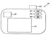
図1は、表示装置10のある実施形態のブロック図である。図2は、図1の表示装置10の背面図である。図1および図2に示されているように、表示装置10は、デジタルカメラ12の形をとり、そのボディ20は、レンズ系23、イメージセンサー24、信号プロセッサ26、任意的なディスプレイドライバ28およびディスプレイ30を有する画像撮影システム22を含んでいる。動作では、場面からの光はレンズ系23によって結像されて、イメージセンサー24上に像を形成する。レンズ系23は一つまたは複数の要素を有することができる。
FIG. 1 is a block diagram of an embodiment of a
レンズ系23は固定焦点型であってもよいし、手動または自動的に調整可能であってもよい。図1に示された実施形態では、レンズ系23は自動的に調整される。レンズ系23は、単一の焦点距離で、手動フォーカスまたは固定焦点といった単純なものであってもよい。図1に示した実施例では、撮影レンズユニット22はモーター付きの6倍ズームレンズユニットで、単数または複数の可動要素(図示せず)は単数または複数の固定要素(図示せず)に対してレンズドライバ25によって駆動される。レンズドライバ25はレンズ系23のレンズ焦点距離およびレンズ焦点位置の両方を制御し、レンズ焦点距離および/またはレンズ焦点位置を、信号プロセッサ26、任意的な自動距離計システム27および/またはコントローラ32からの信号に基づいて設定する。
The
レンズ系23の焦点距離および/または焦点位置は、多様な既知の方針を使って自動的に選択できる。たとえば、ある実施例では、イメージセンサー24は、いわゆる「焦点通過(through focus)」または「全方向スキャン(whole way scanning)」アプローチを使ってマルチスポット・オートフォーカスを提供するために使われる。そのようなアプローチでは、場面は領域またはスポットのグリッドに分割され、最適な焦点距離は各画像領域について決定される。各領域についての最適な焦点距離は、レンズ系23を、近い焦点距離から無限遠位置まで焦点距離位置の範囲を通じて動かすことによって決定される。デジタルカメラ12の設計に依存して、異なる焦点距離において4枚から32枚までの画像を取り込む必要があることがありうる。典型的には、8つの異なる距離で画像を取り込めば好適な精度が提供される。
The focal length and / or focal position of the
取り込まれた画像データは次いで解析されて、各画像領域についての最適な焦点距離が決定される。この解析は、センサー信号を一つまたは複数のフィルタを使って帯域通過フィルタ処理することで始まる。これは1995年12月11日にXie et al.によって出願された、本出願人に譲渡された米国特許第5,874,994号において記載されているとおりである。この開示はここに参照によって組み込まれる。各画像領域についての帯域通過フィルタ出力の絶対値は、次いで、その画像領域についてその焦点距離における焦点値を決定するためにピーク検出される。各画像領域についての焦点値が各撮影焦点距離位置について決定されたのち、各画像領域についての最適な焦点距離が決定できる。これは、最大の焦点値を与える撮影焦点距離を選択することによって、あるいは大きいほうから2つの焦点値を与えた2つの測定された撮影焦点距離の間でさまざまな補間法を使って中間的な距離値を推定することによってである。 The captured image data is then analyzed to determine the optimal focal length for each image region. This analysis begins with bandpass filtering the sensor signal using one or more filters. This is as described in commonly assigned US Pat. No. 5,874,994, filed Dec. 11, 1995 by Xie et al. This disclosure is hereby incorporated by reference. The absolute value of the bandpass filter output for each image region is then peak detected to determine the focus value at that focal length for that image region. After the focus value for each image region is determined for each shooting focal length position, the optimum focal length for each image region can be determined. This can be done either by selecting the shooting focal length that gives the maximum focus value, or by using various interpolation methods between two measured shooting focal lengths given the two largest focus values. By estimating the distance value.
デジタル画像を撮影するために使用されるべきレンズ焦点距離がこれで決定できる。ある好ましい実施形態では、目標オブジェクト(たとえば撮影される人物)に対応する諸画像領域が決定される。次いで、それらの画像領域について最良の焦点を与える焦点位置が設定される。たとえば、ある場面の画像は複数の区画に分割されることができる。画像の各区画に含まれる高周波成分を表す焦点評価値を決定することができ、その焦点評価値を使ってオブジェクト距離を決定することができる。このことは1996年10月15日にOmata et al.によって出願された、“Method Of Automatic Object Detection In An Image”と題する、本出願人に譲渡された米国特許第5,877,809号において記載されているとおりである。この開示はここに参照によって組み込まれる。目標オブジェクトが動いている場合、オブジェクト追跡を実行してもよい。このことは1996年10月26日にOmata et al.によって出願された“Detecting Compositional Change in Image”と題する、本出願人に譲渡された米国特許第6,067,114号において記載されているとおりである。この開示はここに参照によって組み込まれる。ある代替的な実施形態では、「全方向スキャン」によって決定される焦点値が大まかな焦点位置を設定するために使われ、これは精細焦点モードを使って洗練される。このことは、1998年10月11日にOmata et al.によって出願された、“Automatic Focusing Apparatus and Method”と題する、本出願人に譲渡された米国特許第5,715,483号において記載されているとおりである。この開示はここに参照によって組み込まれる。 The lens focal length to be used for taking a digital image can now be determined. In a preferred embodiment, image areas corresponding to a target object (eg, a person to be photographed) are determined. Then, the focus position that gives the best focus for those image areas is set. For example, an image of a scene can be divided into a plurality of sections. A focus evaluation value representing a high-frequency component included in each section of the image can be determined, and the object distance can be determined using the focus evaluation value. This is as described in U.S. Pat. No. 5,877,809, assigned to the present applicant, entitled “Method Of Automatic Object Detection In An Image”, filed by Omata et al. It is. This disclosure is hereby incorporated by reference. If the target object is moving, object tracking may be performed. This is as described in commonly assigned US Pat. No. 6,067,114 entitled “Detecting Compositional Change in Image” filed by Omata et al. On October 26, 1996. This disclosure is hereby incorporated by reference. In an alternative embodiment, the focus value determined by “omnidirectional scanning” is used to set a rough focus position, which is refined using a fine focus mode. This is as described in US Pat. No. 5,715,483, assigned to the present applicant, entitled “Automatic Focusing Apparatus and Method” filed by Omata et al. . This disclosure is hereby incorporated by reference.
ある実施形態では、デジタルカメラ12のためのオートフォーカス情報を提供するための帯域通過フィルタ処理およびその他の計算は、デジタル信号プロセッサ26によって実行される。この実施形態では、デジタルカメラ12は、自動的にレンズ焦点位置を設定するために、特別に適応されたイメージセンサー24を使用する。これは1994年12月30日にParulski et al.によって出願された、“An Electronic Camera With Rapid Automatic Focus Of An Image Upon A Progressive Scan Image Sensor”と題する、本出願人に譲渡された米国特許第5,668,597号において示されているとおりである。この開示はここに参照によって組み込まれる。'597特許において記載されているように、センサー光素子の一部の行しか(たとえば4分の1の行しか)焦点を決定するために使われない。他の行はセンサー読み出しプロセスの間は消去される。これはセンサー読み出し時間を減らし、よってレンズ系23の焦点を合わせるために必要とされる時間を短縮する。
In some embodiments, bandpass filtering and other calculations to provide autofocus information for digital camera 12 are performed by
代替的な実施形態では、デジタルカメラ12は、別個の光学式またはその他の型(たとえば超音波)の距離計27を使って、画像の被写体を同定し、その被写体への距離について適切な、レンズ系23のための焦点位置を選択する。距離計27はレンズドライバ25を直接動作させることもできるし、あるいは図1に示すように、信号プロセッサ26またはコントローラ32に信号を提供し、その信号からプロセッサ26またはコントローラ32が画像撮影に使われるべき信号を生成できるようにすることもできる。当業者に知られている幅広い範囲の好適な多重センサー距離計27が使用のために好適である。たとえば、1993年11月30日にTabata et al.によって出願された、“Compact Camera With Automatic Focal Length Dependent Exposure Adjustments”と題する米国特許第5,440,369号は、そのような距離計27の一つを開示している。その開示はここに参照によって組み込まれる。距離計27によって提供される焦点決定は、単一スポット型でも、多重スポット型であってもよい。好ましくは、焦点決定は多重スポットを使用する。多重スポット焦点決定においては、場面は領域すなわちスポットのグリッドに分割され、最適な焦点距離が各スポットについて決定される。スポットの一つが画像の被写体として同定され、そのスポットについての焦点距離がレンズ系23の焦点を設定するために使用される。
In an alternative embodiment, the digital camera 12 uses a separate optical or other type (e.g., ultrasound)
レンズドライバ25とカメラコントローラ32との間でフィードバックループが確立され、カメラコントローラ32はレンズ系23の焦点位置を精密に設定できるようになる。
A feedback loop is established between the
レンズ系23はまた任意的に、可変ズームを提供するよう調整可能である。図示された実施形態において、レンズドライバ25は自動的に、レンズ系23の一つまたは複数の可動要素(図示せず)の一つまたは複数の固定要素(図示せず)に対する位置を、信号プロセッサ26、自動距離計システム27および/またはコントローラ32からの信号に基づいて調整してズーム倍率を提供する。レンズ系23は固定倍率であってもよいし、手動で調節できてもよいし、および/または調整可能なズームを提供するためのその他の既知の構成を用いてもよい。
レンズ系23によってイメージセンサー24上に結像された、場面からの光は、その場面の画像を表す画像信号に変換される。イメージセンサー24は電荷結合素子(CCD)、相補的金属酸化物センサー(CMOS)あるいは当業者に既知の他の任意の電子イメージセンサーであってよい。画像信号はデジタル形式であってもアナログ形式であってもよい。
The light from the scene imaged on the
信号プロセッサ26は、イメージセンサー24から画像信号を受け取り、画像信号をデジタルデータの形の画像に変換する。デジタル画像は一つまたは複数のスチール画像を有していてもよいし、多重スチール画像を有していてもよいし、および/またはビデオセグメントのような見かけ上動いている画像のストリームを有していてもよい。デジタル画像データが見かけ上動いている画像のストリームを有する場合には、デジタル画像データをなす画像データは、インターリーブまたはインターレースされた画像形式、一連のスチール画像および/またはデジタルビデオ分野の当業者に既知のその他の形式で保存されることができる。
The
信号プロセッサ26は、デジタル画像を形成するときに、さまざまな画像処理アルゴリズムを画像信号に対して適用することができる。これらは、色および露出のバランス取り、補間および圧縮を含むがこれに限られるものではない。画像信号がアナログ信号形式である場合、信号プロセッサ26はそうしたアナログ信号のデジタル形式への変換もする。
The
コントローラ32は、画像処理動作の間、表示装置10の動作を制御する。表示装置10は画像撮影システム22、ディスプレイ30およびメモリ40のようなメモリを含んでいるが、これに限られるものではない。コントローラ32は、イメージセンサー24、信号プロセッサ26、ディスプレイ30およびメモリ40をして、ユーザー入力システム34から受け取った信号、信号プロセッサ26からのデータおよび任意的なセンサー36から受け取ったデータに応答して、原画像を撮影し、保存するようにさせる。コントローラ32は、プログラム可能汎用マイクロプロセッサのようなマイクロプロセッサ、専用マイクロプロセッサもしくはマイクロコントローラ、離散素子の組み合わせまたは表示装置10の動作を制御するのに使用できる他の任意のシステムを有していることができる。
The
コントローラ32は、ユーザー入力システム34と協働して、表示装置10がユーザーと対話できるようにする。ユーザー入力システム34は、ユーザーからの入力を受け取ってその入力を表示装置10を動作させる際にコントローラ32が使用できる形に変換することのできるいかなる形のトランスデューサまたはその他のデバイスを有していてもよい。たとえば、ユーザー入力システム34はタッチスクリーン入力、タッチパッド入力、四方向スイッチ、六方向スイッチ、八方向スイッチ、スタイラスシステム、トラックボールシステム、ジョイスティックシステム、音声認識システム、ジェスチャー認識システムまたはその他の同様なシステムを有していることができる。図1および図2に示した表示装置10のデジタルカメラ12の実施形態においては、ユーザー入力システム34はシャッタートリガーボタン60を含んでおり、これは画像を撮影する意思を示すトリガー信号をコントローラ32に送る。
The
図1および図2に示した実施形態では、ユーザー入力システム34は広角ズームアウトボタン62および望遠ズームボタン64をも含んでいる。これらはコントローラ32と協働して、レンズ系23のズーム設定を制御するもので、広角ズームアウトボタン62が押下されているときにはレンズ系23をズームアウトさせ、望遠ズームボタン64が押下されているときにはズームインさせる。広角ズームアウトレンズボタン62および望遠ズームボタン64は、信号プロセッサ26をして、形成されるデジタル画像が実際に光学レンズ系によって与えられているのとは異なるズーム設定で撮影されたかのように見えるように画像信号を処理させる信号を提供するために使われることもできる。これは、イメージセンサー24からの画像信号の部分集合を使い、画像信号のその部分集合を補間してデジタル画像を形成することによってできる。ユーザー入力システム34はまた、図2に示される編集ボタン68を含むその他のボタンを含むこともできる。その機能についてはのちにより詳細に述べる。
In the embodiment shown in FIGS. 1 and 2, the
センサー36は任意的で、光センサーおよびその他のセンサーを含むことができる。その他のセンサーとは、表示装置10を取り巻く環境の条件を検出し、その情報を表示装置10の動作を管理するのにコントローラ32が使用できる形に変換するのに使用できるものである。センサー36はまた、セキュリティ目的および影響型画像処理(affective imaging)の目的でユーザーの特徴を検出するよう適応されたバイオメトリックセンサーを含むこともできる。
コントローラ32は、トリガー条件が検出されたときに、画像信号および対応するデジタル画像が形成されるようにする。典型的には、トリガー条件が発生するのは、ユーザーがシャッタートリガーボタン60を押下したときであるが、コントローラ32は特定の時刻に、あるいはシャッタートリガーボタン60の押下後のある特定の時間に、トリガー条件が存在すると判定することもできる。あるいはまた、コントローラ32は任意的なセンサー36がある種の環境条件を検出したときにトリガー条件が存在すると判定することもできる。
The
コントローラ32は、各画像に付随するメタデータを生成するのに使うこともできる。メタデータとは、デジタル画像またはデジタル画像の部分に関係するが、必ずしも画像そのものにおいて観測可能ではないデータである。これに関し、コントローラ32は、信号プロセッサ26、カメラユーザー入力システム34およびその他のセンサー36から信号を受け取ることができ、任意的にそのような信号に基づいてメタデータを発生させる。メタデータは、原画像が撮影された時刻、日付および場所、イメージセンサー24の種類、モード設定情報、積分時間情報、原画像を撮影するために使われたプロセスを特徴付ける撮影レンズユニット設定情報、ならびに原画像を形成するために表示装置10によって使用されたプロセス、方法およびアルゴリズムといった情報を含むことができるが、これに限られない。メタデータはまた、コントローラ32によって決定されたり、あるいは表示装置10内の任意のメモリに保存されたりする、表示装置10を同定する情報のような他の任意の情報、および/またはそのメタデータが付随するデジタル画像を表現する、あるいは他の仕方で処理するための命令をも含みうるが、それに限られない。メタデータはまた、特定のメッセージを呈示されるときのデジタル画像に組み込むための命令をも有しうる。そのようなメッセージは、デジタル画像が呈示または表現されるときに表現されるべきテキストメッセージであることができる。メタデータはまた音声信号を含んでいてもよい。メタデータはさらに、デジタル画像データを含んでいてもよい。メタデータはまた、表示装置10に入力される他の任意の情報を含むこともできる。
The
デジタル画像および任意的なメタデータは圧縮された形で保存されることができる。たとえば、デジタル画像が一連のスチール画像を有する場合、スチール画像は、たとえばJPEG(Joint Photographic Experts Group)ISO10918-1(ITU-T.81)規格を使うなどして圧縮された形で保存できる。JPEG圧縮された画像データは、電子情報技術産業協会(Japan Electronics and Information Technology Industries Association)JEITA CP-3451によって発表された交換可能画像ファイルフォーマット(Exchangeable Image File Format)バージョン2.2において定義されているいわゆる「Exif」画像フォーマットを使って保存される。同様に、MPEG-4(Motion Pictures Expert Group)またはアップルQuickTime(商標)規格といったその他の圧縮システムをビデオ形式のデジタル画像データを保存するために使うこともできる。その他の画像圧縮および保存形式を使うこともできる。 Digital images and optional metadata can be stored in a compressed form. For example, if the digital image has a series of still images, the still images can be stored in a compressed form, for example using the JPEG (Joint Photographic Experts Group) ISO10918-1 (ITU-T.81) standard. JPEG-compressed image data is a so-called “Exchangeable Image File Format” version 2.2 published by Japan Electronics and Information Technology Industries Association JEITA CP-3451. Saved using Exif image format. Similarly, other compression systems such as MPEG-4 (Motion Pictures Expert Group) or Apple QuickTime (TM) standard can be used to store digital image data in video format. Other image compression and storage formats can also be used.
デジタル画像およびメタデータはメモリ40のようなメモリに保存することができる。メモリ40は、半導体、磁気、光学式その他のデータ記憶装置を含む従来型のメモリ装置を含みうる。メモリ40は表示装置10内に固定されていてもよいし、取外し可能であってもよい。図1の実施形態では、表示装置10は、取外し可能なメモリカードのようなリムーバブルメモリ48を保持し、リムーバブルメモリ48と通信するためのリムーバブルメモリインターフェース50をもつメモリカードスロット46を有するものとして示されている。デジタル画像およびメタデータはまた、表示装置10の外部にあるパソコン、コンピュータネットワークまたは他の画像処理システムといったリモート・メモリシステム52に保存することもできる。
Digital images and metadata can be stored in a memory such as
図1および図2に示された実施形態では、表示装置10は、リモート・メモリシステム52と通信するための通信モジュール54を有している。通信モジュール54はたとえば、光学式、電波式あるいはその他、画像その他のデータを光学信号、電波信号その他の形態の信号によって離れた表示装置に伝えられる形に変換するトランスデューサでありうる。通信モジュール54はまた、ホストコンピュータやネットワーク(図示せず)からデジタル画像その他の情報を受信するのに使うこともできる。コントローラ32はまた、リモートトリガーボタン(図示せず)のような離れた制御装置(図示せず)からの信号を含むがそれに限られない、通信モジュール54によって受信された信号から情報および命令を受け取り、表示装置10をそのような信号に従って動作させることができる。
In the embodiment shown in FIGS. 1 and 2, the
信号プロセッサ26および/またはコントローラ32はまた、画像信号またはデジタル画像を使って、表示装置10に保存されている原画像に対応する見かけを有し、ディスプレイ30上での呈示のために適応されている評価画像を形成する。これにより表示装置10のユーザーは、ディスプレイ30のようなディスプレイを使って、表示装置10で利用可能な原画像に対応する画像を閲覧することができるようになる。そのような画像は、たとえば、画像撮影システム22によって撮影された、および/または通信モジュール54によるなどその他の仕方で取得され、メモリ40もしくはリムーバブルメモリ48のようなメモリに保存された画像を含むことができる。
The
ディスプレイ30はたとえば、カラー液晶ディスプレイ(LCD: liquid crystal display)、有機発光ディスプレイ(OLED: organic light emitting display)――有機ELディスプレイ(OLED: organic electroluminescent display)としても知られる――その他の種類のビデオディスプレイであってよい。ディスプレイ30は図2に示したように外部にあってもよいし、ファインダーシステム38内などで使う内部的なものであってもよい。あるいはまた、表示装置10は、外部に一つ、内部に一つなど複数のディスプレイを有していてもよい。
The
信号プロセッサ26および/またはコントローラ32はまた、コントローラ32と表示装置10のユーザーとの間の対話的なやりとりを可能にしうる、ディスプレイ30上で呈示するためのテキスト、グラフィック、アイコンその他の情報のような他の画像を協力して生成することができる。ディスプレイ30が表示装置10のユーザーに情報を提供し、表示装置10のユーザーがユーザー入力システム34を使って対話的に表示装置10に情報を提供するのである。表示装置10はまたセグメントLCDまたはLED表示(図示せず)のようなその他の表示手段も有していていることができる。これも信号プロセッサ26および/またはコントローラ32がユーザー10に情報を提供するのを可能にすることができる。この機能は、動作モードの確定、制御設定やユーザーの好み設定の入力、表示装置10のユーザーへの警告や指示の提供といったさまざまな目的のために使われる。音声信号、振動、触覚フィードバックその他の形の信号を生成するための既知のシステムやアクチュエータといったその他のシステムも、表示装置10に組み込まれ、該表示装置10のユーザーに情報、フィードバック、警告を与えるのに使われることができる。
典型的には、ディスプレイ30はイメージセンサー24より画像解像度が低い。したがって、信号プロセッサ26は、ディスプレイ30上での呈示のために適応された評価画像を形成する際には画像信号またはデジタル画像の解像度を減らす。全体としての画像解像度を下げるためには、ダウンサンプリングその他従来の技術を使うことができる。たとえば、1990年3月15日にクチュタ(Kuchta)らによって出願された「完全な解像度および低下した解像度の画像の多フォーマット保存を提供する電子スチルカメラ」(Electronic Still Camera Providing Multi-Format Storage Of Full And Reduced Resolution Images)と題する、本出願人に譲渡された米国特許第5,164,831号において記載されているような再サンプリング技術を使うことができる。評価画像は任意的にメモリ40のようなメモリに保存されてもよい。評価画像は、ディスプレイ30を駆動するのに使用されうる任意的なディスプレイドライバ28に与えられるよう適応されることもできる。あるいはまた、評価画像は、ディスプレイ30に該評価画像を直接呈示させるような形で信号プロセッサ26から送信できる信号に変換されることもできる。こうする場合には、ディスプレイドライバ28は省略できる。
Typically, the
表示装置10は処理するための原画像をさまざまな仕方で取得できる。たとえば、表示装置10は、上述したように画像撮影システム22を使って原画像を撮影することができる。画像撮影システム22を使って原画像を取得するのに使用できる画像生成プロセスは撮影プロセスを含んでおり、任意的にまた、構図プロセスおよび検証過程を含んでいる。
The
該任意的な構図プロセスの間、コントローラ32は任意的に電子ファインダー効果をディスプレイ30上で提供する。これに関し、コントローラ32は信号プロセッサ26をしてイメージセンサー24と協力して構図の間にプレビューデジタル画像を撮影し、対応する評価画像をディスプレイ30上に表示するようにさせる。
During the optional composition process, the
図1および図2に示した実施形態では、コントローラ32はシャッタートリガーボタン60が半押しの位置まで動かされたときに画像構図プロセスにはいる。しかし、構図プロセスにいつはいるかを決めるのはこれ以外の方法を用いてもよい。たとえば、図2に示したたとえば編集ボタン68のようなユーザー入力システム34の一つを表示装置10のユーザーが押下することができ、それをコントローラ32が構図プロセスにはいる命令として解釈することができる。構図の間に呈示される評価画像は、ユーザーが原画像の撮影のための場面の構図を決める助けとなりうる。
In the embodiment shown in FIGS. 1 and 2, the
撮影プロセスは、コントローラ32がトリガー条件が存在すると判断することに反応して実行される。図1および図2の実施形態では、トリガー信号はシャッタートリガーボタン60が完全押下状態にまで動かされたときに生成され、コントローラ32は該トリガー信号を検出したときにトリガー条件が存在すると判断する。撮影プロセスの間、コントローラ32は信号プロセッサ26をしてイメージセンサー24からの画像信号を取得し、画像信号を処理して原デジタル画像をなすデジタル画像データを形成するようにさせる撮影信号を送る。
The imaging process is executed in response to the
検証プロセスの間、前記原デジタル画像に対応する評価画像がディスプレイ30での呈示のために、信号プロセッサ26によって画像信号に基づいて任意的に形成される。ある代替的な実施形態では、信号プロセッサ26はそのような画像信号をデジタル画像に変換し、次いで前記原デジタル画像から対応する評価画像を導出する。対応する評価画像はディスプレイ30に供給され、一定期間にわたって呈示される。これによりユーザーはそのデジタル画像が好ましい見え方をしていることを検証することができる。
During the verification process, an evaluation image corresponding to the original digital image is optionally formed by the
表示装置10は、原画像を画像撮影以外の方法で取得することもできる。原画像はたとえば、そのような画像がメモリインターフェース50に動作的に付随するリムーバブルメモリ上に記録されているとき、表示装置10に伝送されることもできる。あるいはまた、原画像は通信モジュール54によって受信されることもできる。たとえば、通信モジュール54が携帯電話網によって通信するよう適応されている場合には、通信モジュール54は携帯電話番号またはその他の識別番号と関連付けることができ、たとえばデジタルカメラ付き電話のユーザーのような前記携帯電話網の他のユーザーがその番号を使って表示装置10との通信リンクを確立して画像を送信し、通信モジュール54が受け取れる画像を送信することができる。
The
このように、表示装置10が画像を受け取るのはさまざまな方法があり、よって表示装置10が画像撮影システムを有しているかどうかは本質的ではない。表示装置10に画像をインポートするための上述したような他の手段が利用できさえすればよいのである。
As described above, there are various ways in which the
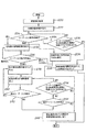
図3は、たとえば表示装置10を使って保管画像中の重要領域を決定する方法の第一の実施形態を描いた流れ図を示している。本方法によれば、原画像が取得される(ステップ100)。これは撮影によってなされてもよいし、上で議論したように原画像をインポートしたり、他の従来式の保管画像取り込みもしくはダウンロード技術を使ってなされてもよい。たとえば、上で議論したように、原画像は、画像撮影システム22によって取り込まれたり、リムーバブルメモリ48からダウンロードされたり、あるいは他の仕方で通信モジュール54によって取得されたりしたいかなるデジタル画像であってもよい。
FIG. 3 shows a flowchart depicting a first embodiment of a method for determining an important region in a stored image using, for example, the
原画像が取得されたのち、評価画像が呈示される(ステップ102)。ディスプレイ30の画像処理機能が十分な画像解像度を有するなどのようなある種の状況下では、評価画像は原画像であってもよい。原画像がディスプレイ30を使って呈示できるよりも多くの画像情報を提供するような状況では、コントローラ32は評価画像の形成を引き起こすが、それには原画像をダウンサンプリングしたりその他の仕方で適応させたりして、上述したように原画像に基づいて評価画像を形成する。そのような評価画像は、原画像の見え方に対応する見え方を有しており、ディスプレイ30を使った呈示のために適応されている。
After the original image is acquired, an evaluation image is presented (step 102). Under certain circumstances, such as when the image processing function of the
次いで、ユーザー入力動作が起こったかどうかが判定される(ステップ104)。典型的には、ユーザー入力動作は、ユーザー入力システム34によって感知されることのできる何らかの動作である。これは多様な形態を取ることができる。たとえば、ユーザー入力動作は、図2に示される編集ボタン68を押すことであってもよい。この例では、編集ボタン68が押されると、ユーザー入力システム34はコントローラ32によって受信される編集信号を発生させる。コントローラ32が編集信号を受け取ると、コントローラ32はユーザー入力動作が発生したと判定する。ユーザー入力動作は幅広い多様なその他の形態を取ることもでき、そのほんの一部についてのちにより詳細に述べる。ユーザー入力システム34およびコントローラ32はユーザー入力動作のそのような種々の形態と協働するよう適応されている。
It is then determined whether a user input action has occurred (step 104). Typically, a user input action is any action that can be sensed by the
図3の実施形態では、ユーザー入力動作が検出されたとき、コントローラ32は原画像の諸部分の集合の少なくとも一つの部分を指定する(ステップ106)。これに関し、コントローラ32は、任意的に信号プロセッサ26と協働して、原画像内に異なる諸部分の集合を定義する。各部分は原画像の少なくとも一部を含んでいる。該集合内の各部分の大きさ、位置、縦横比および形状は変わりうる。諸部分の少なくとも一つは、原画像の中心でない部分を中心とすることができる。諸部分の集合は、多様な異なる諸部分を組み込みうる。ある実施例では3から30個の間の異なる諸部分が提供され、別の実施例では9つの異なる諸部分が提供され、さらに別の実施例では100以上の諸部分が前記集合に組み込まれうる。
In the embodiment of FIG. 3, when a user input action is detected, the
諸部分の集合は、さまざまな同様または異質の形状および大きさを取ることができる。たとえば、ある実施形態では、諸部分のすべては、たとえば原画像によって提供される画像空間の75%を組み込みうる面積を有し、原画像と同じ縦横比を有することができる。しかし、複数の部分はそれらの部分が原画像に対してどこに位置しているかによって互いに異なっている。たとえば、第一の部分は原画像に関して中心が揃っていることができ、一方、少なくとも一つの他の部分は原画像と中心が揃っていない原画像の領域を定義する。たとえば、そのような非中心的なあらかじめ定義された部分は、原画像の水平軸に沿っては原画像の中心にあるが、垂直方向にはたとえば下にずれていて、当該部分の下端が原画像の評価コピーの下端の上に載っていることがありうる。 The collection of parts can take a variety of similar or heterogeneous shapes and sizes. For example, in some embodiments, all of the portions can have an area that can incorporate, for example, 75% of the image space provided by the original image, and can have the same aspect ratio as the original image. However, the plurality of parts differ from each other depending on where those parts are located with respect to the original image. For example, the first portion can be centered with respect to the original image, while at least one other portion defines a region of the original image that is not centered with the original image. For example, such a non-centered predefined part is at the center of the original image along the horizontal axis of the original image, but is shifted downward, for example in the vertical direction, with the lower end of the part being the original. It can be on the bottom of the evaluation copy of the image.
さらに、原画像の部分は、原画像のある部分を重要領域であると指定する際にユーザーにとって有用であると表示装置10の設計者が信じるいかなる仕方で定義されることもできる。上述の例では諸部分は大きさは同一で位置が異なるものとして述べたが、諸部分の大きさ、縦横比、形状またはこれらもしくはその他のパラメータの組み合わせにおいて変動がありうることも可能である。
Furthermore, the portion of the original image can be defined in any way that the designer of the
諸部分の集合は、画像解析ステップ(図示せず)において実行される、原画像の解析に基づいて定義されることもできる。この種のある実施例では、原画像は、焦点が合っている原画像の諸領域を同定するための周波数解析のような既知の諸技法を使って解析されることができ、焦点が合っている領域のうちの種々のものに対応する諸部分を定義することができる。表示装置10がデジタルカメラである別の実施形態では、原画像は、たとえばオートフォーカス・プロセスの間に取得された焦点距離情報に基づいて諸部分に分離されることができる。原画像内で被写体領域の可能性があるなど原画像の有用な諸部分を同定するために、より複雑な場面画像分析技術をコントローラ32および/または信号プロセッサ26によって原画像に適用することもできる。そうした技術にはエッジ検出、照明パターン認識および焦点同定技法が含まれるが、これに限らない。
The set of parts can also be defined based on the analysis of the original image performed in an image analysis step (not shown). In some examples of this type, the original image can be analyzed using known techniques such as frequency analysis to identify regions of the original image that are in focus and are in focus. Portions corresponding to various ones of the existing areas can be defined. In another embodiment, where the
図4は、原画像120の諸部分の集合の図解の一つの例を示している。図4で示されるように、原画像120は諸部分122,124、126、128、130、132、134、136および138に分割されている。この例では、諸部分のそれぞれは他の諸部分とは別個であることが理解されるであろう。しかし、これは必須ではなく、諸部分が少なくとも部分的に重なり合うこともできる。それは図5に図解したとおりである。図5は6つの部分140、142、144、146、148および150の集合を有する原画像120を示しており、諸部分のうちのいくつかが重なり合っている。やはり図5で図解されているように、諸部分は形が異なっていてもよい。
FIG. 4 shows an example of an illustration of a set of parts of the
諸部分の集合からのある第一の部分は、ユーザー入力動作が検出されたときにコントローラ32によって自動的に指定される(ステップ106)。本発明のある実施形態では、コントローラ32は、所定のシーケンスを使って諸部分の集合の諸部分を指定するよう適応されている。たとえば、表示装置10のユーザーが最初に編集ボタン68を押下したとき、コントローラ32は、諸部分の集合からの第一の部分を指定するのを、諸部分のその集合のために指定されている所定のシーケンスに従って行うことができる。しかし、シーケンスおよび指定の順序は決定的ではなく、変わることができる。
A first part from the set of parts is automatically designated by the
コントローラ32および任意的に信号プロセッサ26は指定された部分について部分評価画像が呈示されるようにする(ステップ108)。部分評価画像は、原画像中で現在指定されている部分内に含まれる画像情報を示す。
部分評価画像は多様な方法で形成できる。部分評価画像160の一つの形は図6に示されている。この種の部分評価画像は、図4の部分138のような現在指定されている部分からの画像情報のみを含む画像である。この種の部分評価画像の利点は、指定された部分が原画像の他の画像要素と一緒にディスプレイ30上に呈示されているときの指定された部分の見え方と比べて拡大された見え方を有する指定された部分を示すということである。このため、呈示された部分評価画像を観察するユーザーは、指定された部分をより詳細に見る機会が得られ、それにより、指定された部分が原画像からの他の画像情報と一緒に呈示されたときには指定された部分においてすぐには目につかない、ユーザーが望ましくないと見なしうる誤りまたはその他の画像条件を当該画像中で検出できる。
The partial evaluation image can be formed by various methods. One form of the
部分評価画像162を提示する代替的な実施形態が図7に示されている。図7に示されるように、この実施形態では、部分評価画像162は、原画像120から、現在指定されている部分164の外側にあるマスク166によってマスクされる諸部分も含めた全画像情報をもつものとして提供される。図示した実施例では、マスク166は評価画像の非指定部分に重ねられる不透明領域である。しかし、マスク166が完全に不透明である必要はなく、実際上は、マスク166は、指定された部分164の境界を示す、あるいは評価画像160のその他の部分と視覚的に分離することのできる、評価画像160の見え方へのいかなる形の変更を有していてもよい。たとえば、評価画像160の指定された領域の見え方は白黒で、あるいは色を変えて見えるよう調整されてもよいし、明らかに鮮鋭度を変えて見えるのでもよい。
An alternative embodiment for presenting the
図8に示されるさらに別の実施形態では、原画像120の部分138のような指定された部分は、部分評価画像162において、ディスプレイ30上に呈示される原画像120からの画像情報の実質すべてを有する評価画像160の他の諸部分からは、線のようなセパレーター168を使って区別されて示される。部分評価画像は他の形を取ることもできる。
In yet another embodiment shown in FIG. 8, a designated portion, such as
図3に戻ると、現在指定されている部分を示す部分評価画像の呈示中または呈示後、コントローラ32は、ユーザーリセット動作を検出するためにユーザー入力システム34を監視する(ステップ110)。ユーザーリセット動作は、ユーザー入力システム34によって検出されることができ、コントローラ32にリセット信号を提供する、いかなる形のユーザー動作であってもよい。コントローラ32がそのようなリセット信号を検出すると、コントローラ32は原画像の現在指定されている部分が指定される部分と考えられるべきではないと判断する。ユーザーリセット動作は、ユーザーが別の部分を選択したがっていることを示す、ユーザー入力システム34への命令でありうる。あるいはまた、ユーザーリセット動作は、ユーザーが原画像のいかなる部分も指定したがっていないことを示す信号でありうる。ユーザーが部分を指定しないことを選ぶ場合には、指定プロセスは終了する。
Returning to FIG. 3, during or after presentation of a partial evaluation image showing the currently designated portion, the
ユーザーがリセット動作を入力しない場合、コントローラ32は、指定に基づいて重要領域を決定する(ステップ112)。ある実施例では、重要領域決定は、指定されている部分内の領域が重要領域を含んでいると判定することによってなされる。別の実施例では、重要領域決定は、指定されている部分に基づいて重要領域として使うための原画像を定義することによってなされてもよい。たとえば、図5の部分148が指定部分として選択されている場合、コントローラ32は、重要領域は、重要領域指定部分を含んでいるが必ずしもそれと同じ広がりではない領域であると判定できる。この例では、図9に示すように、指定される領域は、この例では部分148として示される決定された指定部分の位置に基づいて、たとえば異なる形および縦横比を有する、原画像120内に位置する重要領域170であることができる。
If the user does not input a reset operation, the
重要領域が原画像について決定されたのち、その重要領域決定は、何らかの目的のためにコントローラ32によって使用される(ステップ114)。ある実施形態では、コントローラ32は、決定された重要領域に基づいて重要領域データを生成し、生成された重要領域データを原画像に関連付けるよう適応されている。重要領域データは、原画像のどの部分がユーザーによって重要であると指定されたかを原画像のユーザーが判定できるもとになるような情報のデータまたはその他の符号化でありうる。
After the critical area is determined for the original image, the critical area determination is used by the
重要領域データは多様な方法で原画像と関連付けることができる。たとえば、重要領域データは、メタデータとして、原画像に基づいて形成されたデジタル画像中に保存されることができる。あるいはメタデータとして原画像そのものとともに保存されることができる。表示装置10が電子画像撮影ユニットおよびフィルム画像撮影ユニットを組み込んでいる場合、重要領域データは、たとえば光学的または磁気的符号化を使って、フィルム上に記録される原画像ともに保存されることができる。
Critical region data can be associated with the original image in a variety of ways. For example, the important area data can be stored as metadata in a digital image formed based on the original image. Alternatively, it can be stored as metadata along with the original image itself. If the
さらに別の実施形態では、コントローラ32は、重要領域を原画像と関連付けるのを、その重要領域からの画像情報に基づいて修正画像を生成することによって行うこともできる。この修正画像は、原画像またはそれから導出した他の何らかの画像と関連付けられて保存されることができる。該修正画像は、原画像を保持することなく保存されることもできる。この後者の代替法は、表示装置10内のメモリ空間を節約する利点があり、ある種の実施形態では、原画像中の画像情報の一部しか使わないことによって、あるいは原画像に基づいて保存のための画像を形成するのに使われる圧縮パラメータを調整し、原画像の重要領域内の画像要素についてはほどほどの圧縮率を使い、原画像の重要領域内でない領域からの画像情報を保存するためにはより大きな圧縮率を使うようにすることによって、所望の画像を保存するために必要とされるデータ量を減らすことができる。
In yet another embodiment, the
コントローラ32は、決定された重要領域を他の目的のために使うこともできる。たとえば、コントローラ32は、決定された重要領域を、取り込み後画像編集および修正についての決定をする際に使うことができる。たとえば、原画像を形成するためにコントローラ32および/または信号プロセッサ26によって使用される白バランスおよび/または露出設定は、決定された重要領域の解析に基づいて電子的に調整されることができる。さらに、コントローラ32および/または信号プロセッサ26は、重要領域において判別された諸条件に基づいて、種々のカメラ設定を決定することができる。決定された重要領域は次いで、画像トリミングおよび同様のそのような機能のために原画像を編集および修正するために、あるいはその後の画像撮影のための撮影パラメータを定義するために、あるいは原画像ののちの処理および評価、解析および/または使用において使うために原画像と対応付けられることのできるメタデータの形で情報を提供するために使用されることができる。
The
図10および図11は、表示装置10および本発明の方法の別の実施形態を示している。図10および図11の実施形態では、ユーザー指定は、一つのユーザー入力システム34だけを使って実行できる。そのユーザー入力システム34は、この実施形態では原画像のある部分を指定するために使われる編集ボタン68として指定されている。図11の実施形態において示されるように、原画像が取得されたのち(ステップ182)、取得された原画像に基づいて評価画像がディスプレイ30などを使って呈示される(ステップ184)。
10 and 11 show another embodiment of the
コントローラ32は、評価画像の呈示中に表示装置10のユーザーがユーザー入力動作をするかどうかを検出するためにユーザー入力システム34を監視する。コントローラ32が、評価画像の呈示中にユーザーが表示装置10の編集ボタン68を押下するユーザー入力動作をしたことを検出した場合(ステップ186)、コントローラ32は、最初の現在の部分評価画像をディスプレイ30に呈示させる(ステップ188)。該最初の現在の部分評価画像は、あらかじめ定義された諸部分の任意のものに基づいた部分評価画像であってもよい。ある実施形態では、現在の部分評価画像は、原画像と同じ中心をもつ部分評価画像であり、よってズームされた画像の見え方を有する。しかし、これは必須ではなく、初期部分評価画像は原画像のいかなる部分を有していてもよい。
The
ユーザーが時間切れまでの期間内にユーザー入力動作を行わなかった場合(ステップ192)、コントローラ32はこのことから、ユーザーは原画像のいかなる部分も重要領域として指定したくないということを判定できる(ステップ194)。あるいはまた、コントローラ32は、時間切れまでの期間内にユーザー入力動作がないことを、ユーザーが原画像の全体を重要領域として選択することを意味していると解釈することもできる(図示せず)。
If the user does not perform a user input action within the period before the time expires (step 192), the
コントローラ32が、ある進み時間期間後まで継続するユーザー入力動作を検出した場合(たとえば編集ボタン68が3秒後にもまだ押下されている場合)(ステップ190)、コントローラ32は、あらかじめ決められた諸部分の集合からの別の部分を原画像の現在部分として指定し(ステップ196)、その現在指定されている部分を使って部分評価画像をディスプレイ30上に呈示させる(ステップ198)。
When the
コントローラ32は、現在の部分評価画像の呈示中にユーザー入力動作が実行されるかどうかを検出するよう適応されている(ステップ200)。現在の部分評価画像の呈示中にユーザー入力動作が検出された場合には、コントローラ32は、ユーザーがその入力動作を少なくともある進み時間にわたって継続するかどうかを判定する(ステップ202)。たとえば、コントローラ32は、ユーザー相互作用が3秒などのある進み時間期間にわたって持続させられているかどうかを検出することができる。この条件が検出された場合、コントローラ32は、原画像の諸部分の集合から原画像の別の部分を、現在の部分として使用するために選択されるようにする(ステップ196)。次いで部分評価画像が呈示され(ステップ198)、この新しい現在の部分評価画像の呈示中にユーザー入力動作が実行されるかどうかを検出するプロセスが実行される。
The
コントローラ32が、現在の部分評価画像が呈示されている時間切れまでの期間の間にユーザーがユーザー入力動作を行わなかったと判定した場合には、コントローラ32は次いで、現在指定されている部分に基づいて原画像中の重要領域を決定するステップに進む(ステップ206)。任意的に、重要領域はコントローラ32によって、たとえば原画像をトリミングおよび/またはサイズ変更する目的のために使われることもできる(図示せず)。また、任意的に、コントローラ32は、原画像と関連付けて、重要領域を示す情報を記録して、のちの編集プロセスがその重要領域を使ってトリミング画像を生成することができるようにすることもできる(このステップも図示せず)。
If the
図11の実施例の方法を使うことで、原画像中の重要領域を指定するためのワンボタン制御方法を使用しながらも、表示装置10のユーザーが、原画像と中心が同じでない原画像の諸部分のうちから選択できるようにする表示装置10が提供されていることが理解されるであろう。そのようなワンボタンの実施形態は、デジタルカメラ、デジタル画像およびビデオプレーヤーおよび携帯電話のような表示装置において格別の有用性を有し、重要領域の境界の精密な位置合わせを要求することなく画像中の重要領域を指定する便利で迅速な手段を提供する。さらに、この実施形態は、方向性のユーザー入力信号を要求しない。すなわち、ユーザー入力コントロールの動きの方向と指定される部分の位置との間に内在的な相関も見かけの相関もないということである。
By using the method of the embodiment of FIG. 11, the user of the
図12は、本発明の表示装置10のもう一つの実施形態を示している。図12に示した実施形態では、表示装置10は、重要領域指定をするのに使われる2つのボタン、進みボタン210および保存ボタン212を有するユーザー入力システム34を提供する。図13は、図12に示したユーザー入力システム34を使った原画像中の重要領域を決定する方法の一つの実施形態である。図13の実施形態に示されているように、原画像が取得され(ステップ220)、初期評価画像が呈示される(ステップ222)。
FIG. 12 shows another embodiment of the
コントローラ32は、初期評価画像の呈示中、表示装置10のユーザーがユーザー入力動作をその呈示中に行うかどうかを検出するために、ユーザー入力34を監視する。この実施形態では、コントローラ32は、時間切れまで(たとえば10秒)の間に、2つのユーザー入力動作、進みユーザー入力動作と保存ユーザー入力動作を検出するよう適応されている。前記期間の少なくとも一部は、初期評価画像が呈示されている時間に対応する。進みユーザー入力動作を表示装置10のユーザーが使うのは、現在呈示されている部分以外の原画像の部分に基づく評価画像の提示を要求するためである。図12および図13に示した実施形態では、進みユーザー入力動作は進みボタン210を押下することである。保存ユーザー入力動作を使うのは、現在呈示されている部分を指定するためである。図11および図12に示した実施形態では、保存ユーザー入力動作は保存ボタン212を作動させることである。他の形のユーザー入力システム34が使用される場合には、他の入力を与えることができ、進み入力動作および保存入力動作を受け取る目的に使用できることは理解されるであろう。そのいくつかはのちにより詳細に述べる。
The
図13に示した実施形態では、評価画像の呈示の間に表示装置10のユーザーには3つのオプションが利用できる。第一のオプションは、表示装置10のユーザーが進みユーザー入力動作を行うときに発生する。コントローラ32は部分評価画像を呈示し、可能性としてはユーザー選択を受領する諸ステップを進む(ステップ232〜ステップ246)。これについてはのちにより詳細に述べる。第二のオプションでは、ユーザーは、原画像全体に基づいた評価画像を肯定的に指定できる。この場合、原画像全体が重要領域として判定されることができる(ステップ234)。第三のオプションでは、ユーザーは時間切れまでの期間内に何らの動作も行わないことができる(ステップ226)。これが起こった場合は、コントローラ32は、その原画像について重要領域が選択されなかったと判定できる(ステップ228)。あるいはまた、ユーザーが時間切れまでの期間内にいかなる動作もしなかった場合には、コントローラ32は原画像全体が重要領域であると判定できる。
In the embodiment shown in FIG. 13, three options are available to the user of the
時間切れまでの期間中に進みユーザー入力動作が検出されたとき、コントローラ32は、初期部分評価画像をディスプレイ30上に呈示させる(ステップ234)。初期部分評価画像は、あらかじめ定められた諸部分の任意のものに基づく部分評価画像であることができる。ある実施例では、初期部分評価画像は、原画像と中心が同じであり、よって普通にズームされた画像の見え方を有する部分評価画像であってもよいが、これは必須ではない。
When the user input operation is detected during the period until the time expires, the
初期部分評価画像の呈示中、コントローラ32は、表示装置10のユーザーが進みボタン210または保存ボタン212のいずれかを作動させることによってユーザー入力動作を行うかどうかを判別するために、ユーザー入力34を監視する(ステップ236)。初期部分評価画像の呈示中に進みボタン210が作動させられた場合には、コントローラ32は、原画像の現在の部分として、あらかじめ決められた諸部分の集合からの諸部分の別のものを指定することができ(ステップ238)、現在指定されている部分に基づく部分評価画像をディスプレイ30上に呈示させ(ステップ240)、表示装置10のユーザーが現在指定されている部分を評価できるようにする。初期部分評価画像の呈示中に保存ボタン212が作動させられた場合(ステップ236)、コントローラ32は現在指定されている部分、今の場合は初期部分を、原画像の重要領域を決定するために使う(ステップ248)。ユーザー入力動作が受領されない場合には、コントローラ32は時間切れまでの期間にわたって現在の部分評価画像の呈示を継続できる。時間切れまでの期間の終了後(ステップ246)、コントローラ32は随意選択的にその原画像について重要領域が選択されなかったと判定でき(ステップ228)、原画像全体が重要領域をなしていると判定でき、あるいは図示したように初期部分評価画像をなすのに使われている部分に対応する画像の部分が重要領域であると判定することができ、あるいはユーザーの好み設定またはメーカー設定によって指示されるようなその他の動作を行うことができる。
During the presentation of the initial partial evaluation image, the
各部分評価画像の呈示中、コントローラ32は、表示装置10のユーザーが進みボタン210(ステップ242)または保存ボタン212(ステップ244)のいずれかを作動させるかどうかを判別するために、ユーザー入力34を監視する。初期部分評価画像の呈示中に進みボタン210が作動させられた場合には、コントローラ32は、原画像の現在の部分として、あらかじめ決められた諸部分の集合からの諸部分の別のものを指定することができ(ステップ238)、部分評価画像をディスプレイ30上に呈示させ(ステップ240)、表示装置10のユーザーがこの部分評価画像を評価できるようにする。初期部分評価画像の呈示中に保存ボタン212が作動させられた場合、コントローラ32は現在指定されている部分を、ユーザーの好み設定またはメーカー設定に依存して、原画像の重要領域を決定するために使う(ステップ248)。該時間切れまでの期間の終了後(ステップ246)、コントローラ32は原画像全体が重要領域をなしていると判定でき、あるいはその原画像について重要領域が選択されなかったと判定でき(ステップ228)、あるいは初期部分評価画像をなすのに使われている部分に対応する画像の部分が重要領域であると判定することができる(ステップ244)。
During the presentation of each partial evaluation image, the
図11の方法のある代替的な実施形態では、コントローラ32は進みユーザー入力を検出し、原画像の異なる諸部分の集合のうちの一つに基づく各部分評価画像からなる部分評価画像のシーケンス呈示を開始するよう適応されることができる。ユーザーが該部分評価画像の一つの呈示中に保存入力動作を行った場合、コントローラ32はそのユーザーが、原画像の現在呈示されている部分を、重要領域決定に使うために指定したと考える。部分評価画像の呈示中にユーザーが保存入力動作を行わない場合には、コントローラ32は画像全体が重要領域であると判定でき、あるいはユーザーが重要領域のそのような指定をしたくないものと判定できる。
In an alternative embodiment of the method of FIG. 11,
図13に示した方法が表示装置10の多様な実施形態を使って実行できることは理解されるであろう。そうした実施形態には、ユーザーインターフェース入力システム34が少なくとも二つのコントロールを有しているような任意の実施形態が含まれる。たとえば、表示装置10の従来式のカメラの実施形態では、進み入力は望遠ズームボタン64であることができ、保存ボタンはシャッタートリガーボタン60であることができる。同様に、表示装置10が携帯電話またはその他のキーパッドを有する装置である実施形態では、2つのキーの任意の組み合わせがこの目的のために使われることができる。
It will be appreciated that the method illustrated in FIG. 13 can be performed using various embodiments of the
さらに別の実施形態では、図11の方法は、単一のユーザー入力コントロールを使って実施されることもできる。該コントロールの押下が進みユーザー入力としてはたらき、該コントロールを放すことが保存ユーザー入力としてはたらくのである。このようにして、ユーザーコントロールの単一のタッチのみを使って領域が指定されうる。 In yet another embodiment, the method of FIG. 11 can be implemented using a single user input control. The pressing of the control proceeds as a user input, and releasing the control serves as a saved user input. In this way, the region can be specified using only a single touch of the user control.
図14および図15に示されるさらに別の実施形態では、表示装置10は、ジョグダイヤル300を組み込んだ携帯情報端末であるものとして示されている。ジョグダイヤル300は、少なくとも一つの回転(rotation)方向(R)および一つの押下(depression)方向(D)に動作可能である。この実施形態では、ジョグダイヤル300は、ジョグダイヤル300が回転させられたときに回転信号を発生させ、ジョグダイヤル300が押下方向に動かされたときに押下信号を発生させる。コントローラ32は回転信号を進みユーザー入力と解釈し、コントローラ32は押下信号を保存ユーザー入力と解釈する。
In yet another embodiment shown in FIGS. 14 and 15,
上述の諸実施形態では、指定される部分は、該指定される部分が静的で、各部分が原画像のあらかじめ定義された領域を定義しているものであることを示唆するような仕方で記述されてきた。これは必ずしもそうではない。本発明の上述した諸実施形態では、表示装置10のユーザーは、指定される部分の位置およびその他の特性を指定することが許容されうる。図14および図15はこれがなされうる一つの方法を図解している。
In the embodiments described above, the designated parts are in such a way as to suggest that the designated parts are static and that each part defines a predefined area of the original image. Has been described. This is not necessarily so. In the above-described embodiments of the present invention, the user of the
図14は、原画像からの画像情報を含む評価画像を呈示する表示装置10を示している。図14に示されるように、諸部分(260〜276)の集合が原画像中で与えられている。各部分(260〜276)は原画像中で所定のアンカー点に対して位置している。評価画像の呈示中にジョグダイヤル300が回転させられた場合、コントローラ32はこれを進みユーザー入力動作と解釈し、呈示する必要のある少なくとも一つの部分評価画像を決定する。該部分評価画像は、たとえば部分264と関連付けられていることができる。したがって、コントローラ32は、図15に示される初期評価画像302の準備および呈示を引き起こす。
FIG. 14 shows the
初期評価画像302を準備する際、コントローラ32は原画像中での部分形状304を定義し、該部分形状304を原画像中にアンカー点282に対して位置させる。この実施形態では、コントローラ32は、形状指定入力をユーザー入力システム34から受け取るようさらに適応されている。形状指定入力はたとえば、アンカー点に対して位置させられるべき部分形状の大きさを定義する倍率入力を含みうる。たとえば、図15に示されるように、ユーザーがアンカー点282をもつ部分264を指定したのち、表示装置10は初期評価画像302を呈示する。評価画像302の呈示中にジョグダイヤル300が押下された場合には、コントローラ32は、ユーザーが原画像のうち評価画像302に示されている部分に対応する部分を選択指定したいのだと判断することができ、上述したように進むことができる。初期評価画像302の呈示中にジョグダイヤル300が回転させられた場合、コントローラ32はアンカー点290に対する新たな部分形状306または308を定義することができ、ユーザーがジョグダイヤル300を押下したときにユーザーによって選択されているような部分形状306または部分形状308内にある画像情報のみを含む現在の評価画像の形成を引き起こすことができる。新たな部分形状306または308がアンカー点282に対して位置され、縦横比または全体的な形もしくはパターンといった諸部分のその他の特性が同じようにして決定されることができる。
When preparing the
したがって、提供されるのは、方向性入力および諸要素の位置指示を必要とすることなく、原画像の諸部分を重要領域として指定するために使用されることができる表示装置10である。コントローラ32は、この指定をさまざまな目的のために使うよう適応されることができる。該さまざまな目的には、これに限るものではないが、ユーザーの重要領域指定を示すメタデータを生成し、このメタデータを原画像と関連付けることが含まれる。デジタル撮影の場合、コントローラ32はそのような重要領域メタデータを画像と関連付けることができる。それは、メタデータを撮影されたデジタル画像中に保存することによって、あるいはデジタル画像を重要領域メタデータを含む記憶位置と関連付けるデータを保存してメタデータが後刻取得できるようにすることによってである。現画像がたとえば感光性フィルムストリップのような感光性媒体上に撮影される場合には、メタデータは、当技術分野において知られている諸技法を使って、感光性フィルムストリップに光学的に記録されたり、あるいは写真共帯(photographic conscript)上に磁気的に記録されることができる。重要領域データは、原画像をトリミングしたり、原画像についてのサムネイル画像を形成したり、原画像を保存するための圧縮設定を調整したり、あるいはその他多様な用途に使ったりすることもできる。
Thus, what is provided is a
10 表示装置
12 デジタルカメラ
20 ボディ
22 画像撮影システム
23 レンズ系
24 イメージセンサー
25 レンズドライバ
26 信号プロセッサ
27 距離計
28 ディスプレイドライバ
30 ディスプレイ
32 コントローラ
34 ユーザー入力システム
36 センサー
38 ファインダーシステム
40 メモリ
48 リムーバブルメモリ
50 メモリインターフェース
52 リモート・メモリシステム
54 通信モジュール
60 トリガーボタン
62 広角ズームアウトボタン
64 望遠ズームボタン
68 編集ボタン
100 原画像取得ステップ
102 評価画像呈示ステップ
104 ユーザー入力動作検出ステップ
106 部分指定ステップ
108 部分評価画像呈示ステップ
110 ユーザーリセット動作検出ステップ
112 原画像中で重要領域を決定
114 決定された重要領域を使う
120 原画像
122 部分
124 部分
126 部分
128 部分
130 部分
132 部分
134 部分
136 部分
138 部分
140 部分
142 部分
144 部分
146 部分
148 部分
150 部分
160 部分評価画像
162 部分評価画像
164 部分評価画像
166 マスク
168 セパレーター
170 重要領域
180 原画像取得ステップ
182 評価画像を呈示
184 評価画像呈示ステップ
186ユーザー入力動作検出ステップ
188 初期部分評価画像を呈示
190 ユーザー入力動作が少なくともある進み時間期間の間継続したかどうかを判定するステップ
192 ユーザー入力動作がないまま時間切れまでの期間が経過したかどうかを判定するステップ
194 重要領域が選択されなかったことを判定するステップ
196 別の部分を現在部分として指定するステップ
198 現在部分評価画像を呈示するステップ
200 ユーザー入力動作がないまま時間切れまでの期間が経過したかどうかを判定するステップ
202 ユーザー入力動作が少なくともある進み時間期間の間継続したかどうかを判定するステップ
204 ユーザー入力動作がないまま時間切れまでの期間が経過したかどうかを判定するステップ
206 現在指定されている部分を重要領域を決定するために使うステップ
210 進みボタン
212 保存ボタン
220 原画像取得ステップ
222 初期評価画像呈示ステップ
224 ユーザー入力動作検出ステップ
226 ユーザー入力動作がないまま時間切れまでの期間が経過したかどうかを判定するステップ
228 重要領域が選択されなかったことを判定するステップ
234 初期部分評価画像呈示ステップ
236 ユーザー入力動作検出ステップ
238 別の部分を現在部分として指定するステップ
240 現在部分評価画像呈示ステップ
242 進みユーザー入力検出ステップ
244 保存ユーザー入力検出ステップ
246 ユーザー入力動作がないまま時間切れまでの期間が経過したかどうかを判定するステップ
260 部分
262 部分
264 部分
266 部分
268 部分
270 部分
272 部分
274 部分
276 部分
278 アンカー点
280 アンカー点
282 アンカー点
284 アンカー点
286 アンカー点
288 アンカー点
290 アンカー点
292 アンカー点
294 アンカー点
296 アンカー点
300 ジョグダイヤル
302 初期評価画像
306 新しい部分形状
308 新しい部分形状
DESCRIPTION OF SYMBOLS 10 Display apparatus 12 Digital camera 20 Body 22 Image pick-up system 23 Lens system 24 Image sensor 25 Lens driver 26 Signal processor 27 Distance meter 28 Display driver 30 Display 32 Controller 34 User input system 36 Sensor 38 Finder system 40 Memory 48 Removable memory 50 Memory Interface 52 Remote memory system 54 Communication module 60 Trigger button 62 Wide-angle zoom-out button 64 Telephoto zoom button 68 Edit button 100 Original image acquisition step 102 Evaluation image presentation step 104 User input operation detection step 106 Partial designation step 108 Partial evaluation image presentation step 110 User reset operation detection step 112 Decide important region in the original image 114 120 Using the determined important region 120 Original image 122 Part 124 Part 126 Part 128 Part 130 Part 132 Part 134 Part 136 Part 138 Part 140 Part 142 Part 144 Part 146 Part 148 Part 150 Part 160 Part evaluation image 162 Part evaluation image 164 Part Evaluation image 166 Mask 168 Separator 170 Important region 180 Original image acquisition step 182 Evaluation image is presented 184 Evaluation image presentation step 186 User input motion detection step 188 Initial partial evaluation image is presented 190 User input motion continues for at least an advance time period Step 192 for determining whether or not a step 194 for determining whether or not a period until a time-out has passed without any user input operation is performed.
Claims (46)
ディスプレイと、
ユーザー入力動作に反応して非方向性信号を生成するよう適応されているユーザー入力システムと、
原画像全部よりも少ない部分を含む諸部分からなり、原画像と中心が同じでない部分を少なくとも一つ有する、原画像の諸部分の集合を決定し、各非方向性信号に反応して原画像の諸部分の集合のうちの異なる一つを逐次指定するよう適応されており、前記ディスプレイをして、原画像の現在指定されている部分を示す部分評価画像を呈示させ、前記現在指定されている部分に基づいて原画像内の重要領域を決定するよう適応されているコントローラとを有しており、
各部分評価画像が、前記現在指定されている部分が原画像の一部として呈示されるときの倍率よりも大きなある倍率で、前記現在指定されている部分を示すものであることを特徴とする表示装置。 The source of the original image,
Display,
A user input system adapted to generate a non-directional signal in response to user input motion;
Determine the set of parts of the original image that consist of parts that contain less than the entire original image and have at least one part that is not the same center as the original image, and react to each non-directional signal Adapted to sequentially designate a different one of the set of parts of the display, causing the display to present a partial evaluation image showing the currently designated part of the original image, and the currently designated A controller adapted to determine an important region in the original image based on the portion
Each partial evaluation image indicates the currently designated portion at a magnification larger than the magnification at which the currently designated portion is presented as part of the original image. Display device.
ディスプレイと、
進み信号および保存信号を生成するよう適応されているユーザー入力システムと、
前記進み信号を検出し、それに反応して前記ディスプレイをして部分評価画像のシーケンスを呈示させるよう適応されたコントローラとを有する表示装置であって、部分評価画像のそれぞれは原画像の異なる種々の部分の集合のうちの一つの画像内容を表しており、諸部分のあらかじめ定義された集合は原画像と中心が同じでない部分を少なくとも一つ含み、
コントローラは、該コントローラが前記保存信号を検出したときに呈示されている原画像の部分に基づいて、原画像中での重要領域を決定する、ことを特徴とする表示装置。 The source of the original image,
Display,
A user input system adapted to generate a lead signal and a stored signal;
A display device having a controller adapted to detect the advance signal and responsively cause the display to present a sequence of partial evaluation images, each of the partial evaluation images having a variety of different original images Represents the image content of one of the sets of parts, the predefined set of parts includes at least one part whose center is not the same as the original image;
The display apparatus, wherein the controller determines an important region in the original image based on a portion of the original image presented when the controller detects the storage signal.
ディスプレイと、
ユーザー入力動作に反応して非方向性進み信号を生成するよう適応されたユーザー入力システムと、
原画像内の所定のアンカー点を基準として位置している原画像の一つの部分からの画像情報を有する部分評価画像をいくつか定義するよう構成されており、さらに各進み信号に反応して別の部分評価画像をディスプレイ上に呈示させるよう適応されており、さらに、前記非方向性進み信号から、原画像のある部分のユーザー指定を決定し、該指定を使って原画像の重要領域を決定するよう適応されているコントローラとを有する表示装置であって、
少なくとも一つのアンカー点が、少なくとも一つの部分が原画像と中心が同じでなくなるよう位置されることを特徴とする表示装置。 The source of the original image,
Display,
A user input system adapted to generate a non-directional advance signal in response to a user input action;
It is configured to define several partial evaluation images having image information from one part of the original image located with reference to a predetermined anchor point in the original image. The partial evaluation image of the original image is adapted to be presented on the display, and further, a user designation of a part of the original image is determined from the non-directional advance signal, and an important region of the original image is determined using the designation. A display device having a controller adapted to:
A display device, wherein at least one anchor point is positioned such that at least one portion is no longer centered on the original image.
原画像を取得し、
原画像に対応する見かけをもつ評価画像を呈示し、
原画像の異なる諸部分の集合を定義し、ここで各部分は原画像全部よりも少ない部分を含み、前記諸部分の少なくとも一つは原画像と中心が同じでなく、
評価画像の呈示の間に非方向性ユーザー入力動作を検出し、
検出された各非方向性ユーザー入力動作に反応して前記諸部分の集合のうちの一つを指定し、
指定された部分に対応する部分評価画像を呈示し、ここで該部分評価画像は、現在指定されている部分が原画像の一部として呈示されるときの倍率よりも大きなある倍率で、現在指定されている部分を示すものであり、
指定された部分に基づいて重要領域を決定する、
ステップを有することを特徴とする方法。 A method for operating a display device comprising:
Get the original image,
Present an evaluation image with the appearance corresponding to the original image,
Defining a set of different parts of the original image, where each part contains less than the whole original image, at least one of said parts is not centered on the original image,
Detect non-directional user input motion during presentation of evaluation image,
Specifying one of the set of parts in response to each detected non-directional user input action;
A partial evaluation image corresponding to the specified part is presented, where the partial evaluation image is presently specified at a magnification that is greater than the magnification when the currently specified part is presented as part of the original image. It shows the part that has been
Determine important areas based on specified parts,
A method comprising steps.
原画像を取得し、
原画像の評価画像を表示し、
表示されている評価画像に関して方向性入力を含まない進みユーザー入力動作を検出し、
原画像の異なる諸部分の集合から異なる諸部分のシーケンスを前記進みユーザー入力動作に基づいて選択し、
選択された各部分について、現在指定されている部分内に含まれる原画像中の画像情報を示す部分評価画像を呈示し、
保存ユーザー入力動作を検出し、該保存ユーザー入力動作が検出されたときに表示されている選択された部分に基づいて重要領域を決定する、
ステップを有しており、原画像の諸部分の所定の集合のうち少なくとも一つは原画像と中心が同じではないことを特徴とする方法。 A method for operating a display device comprising:
Get the original image,
Display the evaluation image of the original image,
Detect advanced user input actions that do not include directional input for the displayed evaluation image,
Selecting a sequence of different parts from a set of different parts of the original image based on the advance user input action;
For each selected part, present a partial evaluation image showing the image information in the original image included in the currently specified part,
Detecting a saved user input action and determining an important region based on a selected portion displayed when the saved user input action is detected;
A method comprising the steps of: wherein at least one of the predetermined set of portions of the original image is not the same center as the original image.
Applications Claiming Priority (2)
| Application Number | Priority Date | Filing Date | Title |
|---|---|---|---|
| US10/810,283 US8659619B2 (en) | 2004-03-26 | 2004-03-26 | Display device and method for determining an area of importance in an original image |
| PCT/US2005/009698 WO2005098758A1 (en) | 2004-03-26 | 2005-03-24 | Determining area of importance in an image |
Publications (2)
| Publication Number | Publication Date |
|---|---|
| JP2007531934A true JP2007531934A (en) | 2007-11-08 |
| JP2007531934A5 JP2007531934A5 (en) | 2008-04-24 |
Family
ID=34964184
Family Applications (1)
| Application Number | Title | Priority Date | Filing Date |
|---|---|---|---|
| JP2007505140A Pending JP2007531934A (en) | 2004-03-26 | 2005-03-24 | Discrimination of important areas in images |
Country Status (3)
| Country | Link |
|---|---|
| US (1) | US8659619B2 (en) |
| JP (1) | JP2007531934A (en) |
| WO (1) | WO2005098758A1 (en) |
Cited By (2)
| Publication number | Priority date | Publication date | Assignee | Title |
|---|---|---|---|---|
| JP2012010233A (en) * | 2010-06-28 | 2012-01-12 | Canon Inc | Image processing apparatus, image processing system and image processing method |
| KR101400459B1 (en) | 2007-11-29 | 2014-05-28 | 엘지전자 주식회사 | Apparatus and method for displaying |
Families Citing this family (47)
| Publication number | Priority date | Publication date | Assignee | Title |
|---|---|---|---|---|
| JP2006025007A (en) * | 2004-07-06 | 2006-01-26 | Fuji Photo Film Co Ltd | Image processor and image processing program |
| IL162921A0 (en) * | 2004-07-08 | 2005-11-20 | Hi Tech Solutions Ltd | Character recognition system and method |
| US7528846B2 (en) * | 2005-02-23 | 2009-05-05 | Microsoft Corporation | Systems and methods to adjust a source image aspect ratio to match a different target display aspect ratio |
| JP4588642B2 (en) * | 2005-03-15 | 2010-12-01 | 富士フイルム株式会社 | Album creating apparatus, album creating method, and program |
| CA2613998C (en) * | 2005-06-08 | 2016-01-05 | Thomson Licensing | Method, apparatus and system for alternate image/video insertion |
| US8339420B2 (en) * | 2005-06-30 | 2012-12-25 | Panasonic Corporation | Method and apparatus for producing size-appropriate images to be displayed by an electronic device with a small display area |
| US7876334B2 (en) * | 2005-09-09 | 2011-01-25 | Sandisk Il Ltd. | Photography with embedded graphical objects |
| US7697827B2 (en) | 2005-10-17 | 2010-04-13 | Konicek Jeffrey C | User-friendlier interfaces for a camera |
| US8467672B2 (en) * | 2005-10-17 | 2013-06-18 | Jeffrey C. Konicek | Voice recognition and gaze-tracking for a camera |
| KR20070046475A (en) * | 2005-10-31 | 2007-05-03 | 삼성전자주식회사 | Image forming device for changing composition of image and changing method thereof |
| US7986298B1 (en) * | 2005-12-19 | 2011-07-26 | Adobe Systems Incorporated | Identifying changes to an image file |
| US7982747B1 (en) | 2005-12-19 | 2011-07-19 | Adobe Systems Incorporated | Displaying generated changes to an image file |
| JP4125762B2 (en) * | 2006-07-06 | 2008-07-30 | 株式会社スクウェア・エニックス | Online video game control server |
| CN101277387A (en) * | 2007-03-29 | 2008-10-01 | 鸿富锦精密工业(深圳)有限公司 | Electronic device |
| KR100811796B1 (en) * | 2007-03-30 | 2008-03-10 | 삼성전자주식회사 | Mobile terminal and method for displaying image using focus information thereof |
| JP5014241B2 (en) * | 2007-08-10 | 2012-08-29 | キヤノン株式会社 | Imaging apparatus and control method thereof |
| US8300064B2 (en) * | 2008-03-26 | 2012-10-30 | Fujifilm Corporation | Apparatus and method for forming a combined image by combining images in a template |
| US8723922B2 (en) * | 2008-09-25 | 2014-05-13 | Sony Corporation | Single camera device and method for 3D video imaging using a refracting lens |
| US9104984B2 (en) | 2008-11-13 | 2015-08-11 | Sony Corporation | Method and device relating to information management |
| KR101610705B1 (en) * | 2008-12-10 | 2016-04-11 | 삼성전자주식회사 | Terminal having camera and method for processing image thereof |
| KR101657120B1 (en) * | 2010-05-06 | 2016-09-13 | 엘지전자 주식회사 | Mobile terminal and Method for displaying image thereof |
| JP5791256B2 (en) * | 2010-10-21 | 2015-10-07 | キヤノン株式会社 | Display control apparatus and display control method |
| JP5549631B2 (en) * | 2011-03-31 | 2014-07-16 | 株式会社デンソーウェーブ | Portable setting terminal and monitoring system |
| JP5145444B2 (en) * | 2011-06-27 | 2013-02-20 | 株式会社コナミデジタルエンタテインメント | Image processing apparatus, image processing apparatus control method, and program |
| JP5853458B2 (en) | 2011-07-21 | 2016-02-09 | ソニー株式会社 | Mark information recording device and mark information presentation device |
| US8485430B2 (en) | 2011-12-06 | 2013-07-16 | Honeywell International, Inc. | Hand held bar code readers or mobile computers with cloud computing services |
| US8941561B1 (en) * | 2012-01-06 | 2015-01-27 | Google Inc. | Image capture |
| US9041518B2 (en) | 2012-01-26 | 2015-05-26 | Hand Held Products, Inc. | Portable RFID reading terminal with visual indication of scan trace |
| JP6071215B2 (en) * | 2012-02-24 | 2017-02-01 | キヤノン株式会社 | Optical viewfinder and optical apparatus using the same |
| US9443119B2 (en) | 2012-04-20 | 2016-09-13 | Hand Held Products, Inc. | Portable encoded information reading terminal configured to locate groups of RFID tags |
| US8881982B2 (en) | 2012-04-20 | 2014-11-11 | Honeywell Scanning & Mobility | Portable encoded information reading terminal configured to acquire images |
| US9536219B2 (en) | 2012-04-20 | 2017-01-03 | Hand Held Products, Inc. | System and method for calibration and mapping of real-time location data |
| US8727225B2 (en) | 2012-04-20 | 2014-05-20 | Honeywell International Inc. | System and method for calibration and mapping of real-time location data |
| US9013275B2 (en) | 2012-04-20 | 2015-04-21 | Hand Held Products, Inc. | Portable encoded information reading terminal configured to adjust transmit power level |
| US9558386B2 (en) | 2012-05-15 | 2017-01-31 | Honeywell International, Inc. | Encoded information reading terminal configured to pre-process images |
| US9064254B2 (en) | 2012-05-17 | 2015-06-23 | Honeywell International Inc. | Cloud-based system for reading of decodable indicia |
| US9092683B2 (en) | 2012-07-10 | 2015-07-28 | Honeywell International Inc. | Cloud-based system for processing of decodable indicia |
| KR20140112774A (en) * | 2013-03-14 | 2014-09-24 | 삼성전자주식회사 | Image editing method, machine-readable storage medium and terminal |
| JP6102602B2 (en) * | 2013-07-23 | 2017-03-29 | ソニー株式会社 | Image processing apparatus, image processing method, image processing program, and imaging apparatus |
| US9594939B2 (en) | 2013-09-09 | 2017-03-14 | Hand Held Products, Inc. | Initial point establishment using an image of a portion of an object |
| EP2942940A1 (en) * | 2014-05-06 | 2015-11-11 | Nokia Technologies OY | Method and apparatus for defining the visible content of an image |
| JP2016015009A (en) * | 2014-07-02 | 2016-01-28 | ソニー株式会社 | Information processing system, information processing terminal, and information processing method |
| EP3040904B1 (en) | 2014-12-31 | 2021-04-21 | Hand Held Products, Inc. | Portable rfid reading terminal with visual indication of scan trace |
| JP6553418B2 (en) * | 2015-06-12 | 2019-07-31 | パナソニック インテレクチュアル プロパティ コーポレーション オブ アメリカPanasonic Intellectual Property Corporation of America | Display control method, display control device and control program |
| JP6707644B2 (en) * | 2015-12-31 | 2020-06-10 | ローベルト ボツシユ ゲゼルシヤフト ミツト ベシユレンクテル ハフツングRobert Bosch Gmbh | Intelligent distributed vision traffic marker and method thereof |
| US10469726B1 (en) * | 2018-09-19 | 2019-11-05 | Inventec Besta Co., Ltd. | Reversing display system with wireless switching multi-view images and method thereof |
| JP7419723B2 (en) * | 2019-09-25 | 2024-01-23 | 株式会社リコー | Image processing system, image processing device and method |
Citations (6)
| Publication number | Priority date | Publication date | Assignee | Title |
|---|---|---|---|---|
| JPH11313233A (en) * | 1998-04-28 | 1999-11-09 | Kyocera Corp | Digital camera system coupled integrally with auxiliary storage device |
| JP2000287955A (en) * | 1999-04-03 | 2000-10-17 | Konica Corp | Image diagnostic supporting apparatus |
| JP2003153145A (en) * | 2001-11-15 | 2003-05-23 | Canon Inc | Print system, control method therefor, camera and control program |
| JP2003189254A (en) * | 1997-04-16 | 2003-07-04 | Seiko Epson Corp | High-speed image display of digital camera |
| JP2003189177A (en) * | 2001-12-18 | 2003-07-04 | Sharp Corp | Terminal |
| JP2004072655A (en) * | 2002-08-09 | 2004-03-04 | Ricoh Co Ltd | Roi region setting device, electronic camera device, roi region setting method, program, and recording medium |
Family Cites Families (132)
| Publication number | Priority date | Publication date | Assignee | Title |
|---|---|---|---|---|
| US3971065A (en) | 1975-03-05 | 1976-07-20 | Eastman Kodak Company | Color imaging array |
| US4642678A (en) | 1984-09-10 | 1987-02-10 | Eastman Kodak Company | Signal processing method and apparatus for producing interpolated chrominance values in a sampled color image signal |
| US4685143A (en) | 1985-03-21 | 1987-08-04 | Texas Instruments Incorporated | Method and apparatus for detecting edge spectral features |
| US4603966A (en) | 1985-08-28 | 1986-08-05 | Eastman Kodak Company | Film video player/printer with cropping control |
| US4812912A (en) | 1986-05-26 | 1989-03-14 | Minolta Camera Kabushiki Kaisha | Focus detection condition display device for camera |
| JP2556484B2 (en) | 1986-10-20 | 1996-11-20 | キヤノン株式会社 | Figure contour extraction device |
| US5172234A (en) | 1987-08-04 | 1992-12-15 | Canon Kabushiki Kaisha | Camera having an electronic zooming display feature |
| US4969202A (en) | 1988-03-31 | 1990-11-06 | Honeywell Inc. | Image recognition edge detection method and system |
| US5081689A (en) | 1989-03-27 | 1992-01-14 | Hughes Aircraft Company | Apparatus and method for extracting edges and lines |
| US5016107A (en) | 1989-05-09 | 1991-05-14 | Eastman Kodak Company | Electronic still camera utilizing image compression and digital storage |
| US5389988A (en) | 1989-05-22 | 1995-02-14 | Nikon Corporation | Trimming camera |
| US5142380A (en) | 1989-10-23 | 1992-08-25 | Ricoh Company, Ltd. | Image data processing apparatus |
| US5164831A (en) | 1990-03-15 | 1992-11-17 | Eastman Kodak Company | Electronic still camera providing multi-format storage of full and reduced resolution images |
| JPH07175119A (en) | 1990-05-01 | 1995-07-14 | Ricoh Co Ltd | Camera capable of trimming photographing |
| US5103254A (en) | 1990-05-29 | 1992-04-07 | Eastman Kodak Company | Camera with subject highlighting and motion detection |
| US5266985A (en) | 1990-07-16 | 1993-11-30 | Nikon Corporation | Camera with optimum composition determinator |
| US5333029A (en) | 1990-10-12 | 1994-07-26 | Nikon Corporation | Camera capable of detecting eye-gaze |
| US5361119A (en) | 1991-01-08 | 1994-11-01 | Nikon Corporation | Focus state display device for camera |
| JP3139028B2 (en) | 1991-02-04 | 2001-02-26 | 株式会社ニコン | Imaging equipment |
| JP2585874B2 (en) | 1991-03-18 | 1997-02-26 | 富士通株式会社 | Edge detection method for color images |
| US5892991A (en) | 1991-04-30 | 1999-04-06 | Minolta Co., Ltd. | Camera capable of displaying the level of visual effect |
| JP3070624B2 (en) | 1991-05-02 | 2000-07-31 | キヤノン株式会社 | Automatic focus detection device |
| US6256061B1 (en) | 1991-05-13 | 2001-07-03 | Interactive Pictures Corporation | Method and apparatus for providing perceived video viewing experiences using still images |
| US5249056A (en) | 1991-07-16 | 1993-09-28 | Sony Corporation Of America | Apparatus for generating video signals from film |
| JP2763211B2 (en) | 1991-08-07 | 1998-06-11 | 富士写真フイルム株式会社 | camera |
| US5557358A (en) | 1991-10-11 | 1996-09-17 | Minolta Camera Kabushiki Kaisha | Camera having an electronic viewfinder for displaying an object image under different photographic conditions |
| JPH05145818A (en) | 1991-11-21 | 1993-06-11 | Sony Corp | Image pickup device |
| JP3255678B2 (en) | 1992-01-14 | 2002-02-12 | オリンパス光学工業株式会社 | camera |
| JPH05260352A (en) | 1992-03-11 | 1993-10-08 | Sony Corp | Video camera |
| JP2597802B2 (en) | 1992-08-04 | 1997-04-09 | インターナショナル・ビジネス・マシーンズ・コーポレイション | Method for controlling an image capture device, image capture device and user interface |
| DE4340729A1 (en) | 1992-11-30 | 1994-06-01 | Asahi Optical Co Ltd | Compact camera with automatic focal length-dependent exposure settings - calculates values of exposure using weighted average of photometric brightness steps with coeffts. varying according to focus |
| US5373322A (en) | 1993-06-30 | 1994-12-13 | Eastman Kodak Company | Apparatus and method for adaptively interpolating a full color image utilizing chrominance gradients |
| JP3528214B2 (en) | 1993-10-21 | 2004-05-17 | 株式会社日立製作所 | Image display method and apparatus |
| US5404189A (en) * | 1993-11-30 | 1995-04-04 | Eastman Kodak Company | Panoramic viewfinder mask |
| US5563718A (en) | 1993-11-30 | 1996-10-08 | Polaroid Corporation | Image coding by use of discrete cosine transforms |
| JP3427454B2 (en) | 1993-12-21 | 2003-07-14 | 株式会社ニコン | Still camera |
| JPH07226911A (en) | 1994-02-15 | 1995-08-22 | Eastman Kodak Japan Kk | Electronic still camera |
| US5710954A (en) | 1994-02-17 | 1998-01-20 | Olympus Optical Co., Ltd. | Camera system having function for photographing image linked to electronic image |
| JPH07261279A (en) | 1994-02-25 | 1995-10-13 | Eastman Kodak Co | Selection system and method of photograph picture |
| US5563655A (en) | 1994-02-28 | 1996-10-08 | Eastman Kodak Company | Intelligent digital image storage for an electronic camera |
| US5715334A (en) * | 1994-03-08 | 1998-02-03 | The University Of Connecticut | Digital pixel-accurate intensity processing method for image information enhancement |
| US5477264A (en) | 1994-03-29 | 1995-12-19 | Eastman Kodak Company | Electronic imaging system using a removable software-enhanced storage device |
| US5943050A (en) | 1994-04-07 | 1999-08-24 | International Business Machines Corporation | Digital image capture control |
| US5446804A (en) | 1994-04-14 | 1995-08-29 | Hewlett-Packard Company | Magnifying digital image using edge mapping |
| KR100322249B1 (en) | 1994-06-10 | 2002-06-20 | 이중구 | Camera with multi automatic focus adjusting function and control method thereof |
| US5647025A (en) * | 1994-09-20 | 1997-07-08 | Neopath, Inc. | Automatic focusing of biomedical specimens apparatus |
| JPH08110564A (en) | 1994-10-13 | 1996-04-30 | Canon Inc | Optical equipment provided with finder display device |
| EP0713331B1 (en) | 1994-11-17 | 2001-03-14 | Canon Kabushiki Kaisha | Camera control device and method |
| US5496106A (en) | 1994-12-13 | 1996-03-05 | Apple Computer, Inc. | System and method for generating a contrast overlay as a focus assist for an imaging device |
| KR0135815B1 (en) | 1994-12-19 | 1998-06-15 | 김광호 | Data communicating method and device |
| US5672840A (en) * | 1994-12-21 | 1997-09-30 | Trw Inc. | Method and apparatus for automatically orienting a computer display |
| US5828406A (en) | 1994-12-30 | 1998-10-27 | Eastman Kodak Company | Electronic camera having a processor for mapping image pixel signals into color display pixels |
| US5668597A (en) | 1994-12-30 | 1997-09-16 | Eastman Kodak Company | Electronic camera with rapid automatic focus of an image upon a progressive scan image sensor |
| US5784658A (en) | 1995-03-09 | 1998-07-21 | Fuji Photo Film Co., Ltd. | Optical data recording device of camera and lens-fitted photographic film unit |
| US5619738A (en) | 1995-05-02 | 1997-04-08 | Eastman Kodak Company | Pre-processing image editing |
| US5791692A (en) | 1995-05-31 | 1998-08-11 | Eastman Kodak Company | Dual sided photographic album leaf and method of making |
| US5874994A (en) | 1995-06-30 | 1999-02-23 | Eastman Kodak Company | Filter employing arithmetic operations for an electronic sychronized digital camera |
| JP3109421B2 (en) * | 1995-09-08 | 2000-11-13 | 富士ゼロックス株式会社 | Chart processing equipment |
| US5706049A (en) * | 1995-11-30 | 1998-01-06 | Eastman Kodak Company | Camera that records an active image area identifier with an image |
| JPH09163037A (en) | 1995-12-13 | 1997-06-20 | Olympus Optical Co Ltd | Image filing system |
| US5675400A (en) | 1995-12-20 | 1997-10-07 | Eastman Kodak Company | Method of reproducing a portion of a photograph |
| JPH09230476A (en) | 1996-02-20 | 1997-09-05 | Fuji Photo Film Co Ltd | Camera |
| JP3733392B2 (en) | 1996-03-05 | 2006-01-11 | イーストマン コダック カンパニー | Image composition change detection method |
| JPH09243906A (en) | 1996-03-05 | 1997-09-19 | Eastman Kodak Japan Kk | Automatic focusing device and method |
| US6333761B2 (en) | 1996-04-09 | 2001-12-25 | Canon Kabushiki Kaisha | Image pickup apparatus having focus detection area size dependent on aspect ratio |
| JP3752510B2 (en) * | 1996-04-15 | 2006-03-08 | イーストマン コダック カンパニー | Automatic subject detection method for images |
| US5697001A (en) | 1996-04-24 | 1997-12-09 | Eastman Kodak Company | Camera for generating and recording object data with the recorded image |
| US5926218A (en) | 1996-06-04 | 1999-07-20 | Eastman Kodak Company | Electronic camera with dual resolution sensors |
| US5663759A (en) | 1996-06-10 | 1997-09-02 | Industrial Technology Research Institute | Feature processor for a digital camera |
| JPH1013725A (en) | 1996-06-25 | 1998-01-16 | Nikon Corp | Information processor |
| US6249316B1 (en) * | 1996-08-23 | 2001-06-19 | Flashpoint Technology, Inc. | Method and system for creating a temporary group of images on a digital camera |
| US6072586A (en) | 1996-09-04 | 2000-06-06 | Eastman Kodak Company | Computer program product for storing preselected zoom and crop data |
| US6005613A (en) | 1996-09-12 | 1999-12-21 | Eastman Kodak Company | Multi-mode digital camera with computer interface using data packets combining image and mode data |
| US5760917A (en) | 1996-09-16 | 1998-06-02 | Eastman Kodak Company | Image distribution method and system |
| US5897232A (en) * | 1996-09-19 | 1999-04-27 | Eastman Kodak Company | Camera with widthwise pseudo zoom masks and method of exposing a pseudo zoom image |
| KR100261603B1 (en) | 1996-12-06 | 2000-07-15 | 이중구 | Portrait shooting device and method |
| TW352415B (en) | 1996-12-26 | 1999-02-11 | Fuji Photo Film Co Ltd | Still camera |
| US5743609A (en) | 1996-12-31 | 1998-04-28 | Eastman Kodak Company | Method and apparatus for preparing photographic film units having image frame associated encoded information |
| US6252989B1 (en) | 1997-01-07 | 2001-06-26 | Board Of The Regents, The University Of Texas System | Foveated image coding system and method for image bandwidth reduction |
| US5742233A (en) | 1997-01-21 | 1998-04-21 | Hoffman Resources, Llc | Personal security and tracking system |
| US6122455A (en) | 1997-01-24 | 2000-09-19 | Hines; Stephen P. | Lensless viewfinder and lensless viewfinder camera |
| US6269357B1 (en) | 1997-02-06 | 2001-07-31 | Nikon Corporation | Information processing system, apparatus, method and recording medium for controlling same |
| US5822625A (en) | 1997-02-19 | 1998-10-13 | Eastman Kodak Company | Hybrid electronic-film camera |
| US5845166A (en) | 1997-02-20 | 1998-12-01 | Eastman Kodak Company | Hybrid camera with identification matching of film and electronic images |
| US5978016A (en) | 1997-02-20 | 1999-11-02 | Eastman Kodak Company | Electronic camera with internal fixed album memory |
| US5940121A (en) | 1997-02-20 | 1999-08-17 | Eastman Kodak Company | Hybrid camera system with electronic album control |
| JPH10268387A (en) | 1997-03-28 | 1998-10-09 | Fuji Photo Optical Co Ltd | Visual field switching mechanism for finder |
| US5898779A (en) * | 1997-04-14 | 1999-04-27 | Eastman Kodak Company | Photograhic system with selected area image authentication |
| US6075926A (en) | 1997-04-21 | 2000-06-13 | Hewlett-Packard Company | Computerized method for improving data resolution |
| US6215523B1 (en) | 1997-06-10 | 2001-04-10 | Flashpoint Technology, Inc. | Method and system for accelerating a user interface of an image capture unit during review mode |
| US6020920A (en) | 1997-06-10 | 2000-02-01 | Flashpoint Technology, Inc. | Method and system for speculative decompression of compressed image data in an image capture unit |
| US5933137A (en) | 1997-06-10 | 1999-08-03 | Flashpoint Technology, Inc. | Method and system for acclerating a user interface of an image capture unit during play mode |
| US5973734A (en) | 1997-07-09 | 1999-10-26 | Flashpoint Technology, Inc. | Method and apparatus for correcting aspect ratio in a camera graphical user interface |
| US6137534A (en) | 1997-07-10 | 2000-10-24 | Flashpoint Technology, Inc. | Method and apparatus for providing live view and instant review in an image capture device |
| US6047140A (en) | 1997-07-15 | 2000-04-04 | Fuji Photo Film Co., Ltd. | Cartridge, laboratory system, image data recording method, camera and photograph processing method |
| US6262769B1 (en) | 1997-07-31 | 2001-07-17 | Flashpoint Technology, Inc. | Method and system for auto rotating a graphical user interface for managing portrait and landscape images in an image capture unit |
| US6310648B1 (en) | 1997-09-12 | 2001-10-30 | Eastman Kodak Company | User interface for electronic image viewing apparatus |
| US6275260B1 (en) | 1997-09-17 | 2001-08-14 | Flashpoint Technology, Inc. | Positioning stamps in images captured with an image capture unit |
| US6249652B1 (en) | 1997-11-13 | 2001-06-19 | Fuji Photo Film Co., Ltd. | Lens-fitted photo film unit and method of producing photographic print |
| US6205296B1 (en) | 1997-12-12 | 2001-03-20 | Minolta Co., Ltd. | Film information writing device, film information reading device and film information handling device |
| JPH11175330A (en) | 1997-12-17 | 1999-07-02 | Canon Inc | Memory alteration system for camera |
| US6018397A (en) | 1998-02-13 | 2000-01-25 | Eastman Kodak Company | Digital image processing with indication to user of hardcopy output image quality |
| US6091902A (en) | 1998-02-25 | 2000-07-18 | Fuji Photo Film Co., Ltd. | Zoom camera with pseudo zooming function |
| US6215485B1 (en) * | 1998-04-03 | 2001-04-10 | Avid Technology, Inc. | Storing effects descriptions from a nonlinear editor using field chart and/or pixel coordinate data for use by a compositor |
| US6167469A (en) | 1998-05-18 | 2000-12-26 | Agilent Technologies, Inc. | Digital camera having display device for displaying graphical representation of user input and method for transporting the selected digital images thereof |
| US6345274B1 (en) | 1998-06-29 | 2002-02-05 | Eastman Kodak Company | Method and computer program product for subjective image content similarity-based retrieval |
| US6714205B1 (en) * | 1998-08-21 | 2004-03-30 | Canon Kabushiki Kaisha | Image data processing method and apparatus, and image processing system |
| US6097901A (en) | 1998-09-18 | 2000-08-01 | Eastman Kodak Company | Camera having locator for image modification areas |
| JP3596307B2 (en) | 1998-09-28 | 2004-12-02 | 日本ビクター株式会社 | Imaging device |
| US6282317B1 (en) | 1998-12-31 | 2001-08-28 | Eastman Kodak Company | Method for automatic determination of main subjects in photographic images |
| JP3803950B2 (en) * | 1999-03-04 | 2006-08-02 | 株式会社リコー | Image composition processing method, image composition processing apparatus, and recording medium |
| US6287252B1 (en) | 1999-06-30 | 2001-09-11 | Monitrak | Patient monitor |
| US6294993B1 (en) | 1999-07-06 | 2001-09-25 | Gregory A. Calaman | System for providing personal security via event detection |
| JP2001051322A (en) * | 1999-08-05 | 2001-02-23 | Minolta Co Ltd | Camera capable of executing trimming photographing |
| US6584221B1 (en) * | 1999-08-30 | 2003-06-24 | Mitsubishi Electric Research Laboratories, Inc. | Method for image retrieval with multiple regions of interest |
| JP2001100280A (en) | 1999-09-29 | 2001-04-13 | Fuji Photo Optical Co Ltd | Image plane frame switching device for camera |
| JP2001116985A (en) | 1999-10-21 | 2001-04-27 | Canon Inc | Camera with subject recognizing function and subject recognizing method |
| US6282231B1 (en) | 1999-12-14 | 2001-08-28 | Sirf Technology, Inc. | Strong signal cancellation to enhance processing of weak spread spectrum signal |
| US6893396B2 (en) | 2000-03-01 | 2005-05-17 | I-Medik, Inc. | Wireless internet bio-telemetry monitoring system and interface |
| US6438323B1 (en) | 2000-06-15 | 2002-08-20 | Eastman Kodak Company | Camera film loading with delayed culling of defective cameras |
| US6697502B2 (en) | 2000-12-14 | 2004-02-24 | Eastman Kodak Company | Image processing method for detecting human figures in a digital image |
| US6516154B1 (en) | 2001-07-17 | 2003-02-04 | Eastman Kodak Company | Image revising camera and method |
| US6577821B2 (en) | 2001-07-17 | 2003-06-10 | Eastman Kodak Company | Camera having oversized imager and method |
| US6505003B1 (en) | 2001-10-12 | 2003-01-07 | Eastman Kodak Company | Hybrid cameras that revise stored electronic image metadata at film unit removal and methods |
| JP3814514B2 (en) * | 2001-10-23 | 2006-08-30 | キヤノン株式会社 | Image display apparatus, image processing method, and program |
| US7221805B1 (en) * | 2001-12-21 | 2007-05-22 | Cognex Technology And Investment Corporation | Method for generating a focused image of an object |
| US7053953B2 (en) | 2001-12-21 | 2006-05-30 | Eastman Kodak Company | Method and camera system for blurring portions of a verification image to show out of focus areas in a captured archival image |
| US7095907B1 (en) * | 2002-01-10 | 2006-08-22 | Ricoh Co., Ltd. | Content and display device dependent creation of smaller representation of images |
| US7006764B2 (en) * | 2002-11-12 | 2006-02-28 | Eastman Kodak Company | User interface for controlling cropping in electronic camera |
| US7206022B2 (en) * | 2002-11-25 | 2007-04-17 | Eastman Kodak Company | Camera system with eye monitoring |
| JP3841046B2 (en) * | 2002-12-02 | 2006-11-01 | 富士写真フイルム株式会社 | Image display device and print system |
| US7327890B2 (en) * | 2002-12-20 | 2008-02-05 | Eastman Kodak Company | Imaging method and system for determining an area of importance in an archival image |
-
2004
- 2004-03-26 US US10/810,283 patent/US8659619B2/en not_active Expired - Fee Related
-
2005
- 2005-03-24 WO PCT/US2005/009698 patent/WO2005098758A1/en active Application Filing
- 2005-03-24 JP JP2007505140A patent/JP2007531934A/en active Pending
Patent Citations (6)
| Publication number | Priority date | Publication date | Assignee | Title |
|---|---|---|---|---|
| JP2003189254A (en) * | 1997-04-16 | 2003-07-04 | Seiko Epson Corp | High-speed image display of digital camera |
| JPH11313233A (en) * | 1998-04-28 | 1999-11-09 | Kyocera Corp | Digital camera system coupled integrally with auxiliary storage device |
| JP2000287955A (en) * | 1999-04-03 | 2000-10-17 | Konica Corp | Image diagnostic supporting apparatus |
| JP2003153145A (en) * | 2001-11-15 | 2003-05-23 | Canon Inc | Print system, control method therefor, camera and control program |
| JP2003189177A (en) * | 2001-12-18 | 2003-07-04 | Sharp Corp | Terminal |
| JP2004072655A (en) * | 2002-08-09 | 2004-03-04 | Ricoh Co Ltd | Roi region setting device, electronic camera device, roi region setting method, program, and recording medium |
Cited By (2)
| Publication number | Priority date | Publication date | Assignee | Title |
|---|---|---|---|---|
| KR101400459B1 (en) | 2007-11-29 | 2014-05-28 | 엘지전자 주식회사 | Apparatus and method for displaying |
| JP2012010233A (en) * | 2010-06-28 | 2012-01-12 | Canon Inc | Image processing apparatus, image processing system and image processing method |
Also Published As
| Publication number | Publication date |
|---|---|
| US20050212817A1 (en) | 2005-09-29 |
| US8659619B2 (en) | 2014-02-25 |
| WO2005098758A1 (en) | 2005-10-20 |
Similar Documents
| Publication | Publication Date | Title |
|---|---|---|
| JP2007531934A (en) | Discrimination of important areas in images | |
| US7433586B2 (en) | Camera with an auto-focus function | |
| US9462181B2 (en) | Imaging device for capturing self-portrait images | |
| CN111294517B (en) | Image processing method and mobile terminal | |
| US20050134719A1 (en) | Display device with automatic area of importance display | |
| JP5056061B2 (en) | Imaging device | |
| US7880792B2 (en) | Image capturing apparatus with through image display function | |
| US7515197B2 (en) | Digital camera capable of obtaining crop image | |
| KR101610705B1 (en) | Terminal having camera and method for processing image thereof | |
| JP2007295183A (en) | Device, method, and program for reproducing image, and image sensing device | |
| JP2007310813A (en) | Image retrieving device and camera | |
| US20080309785A1 (en) | Photographing apparatus | |
| JP5181841B2 (en) | Imaging apparatus, imaging control program, image reproducing apparatus, and image reproducing program | |
| JP4196393B2 (en) | ID photo system | |
| JP4788172B2 (en) | Imaging apparatus and program | |
| JP4842232B2 (en) | Imaging apparatus and image reproduction apparatus | |
| KR101998846B1 (en) | Terminal having camera and method for processing image thereof | |
| KR101945028B1 (en) | Terminal having camera and method for processing image thereof | |
| JP2003051981A (en) | Digital camera | |
| KR101798019B1 (en) | Terminal having camera and method for processing image thereof | |
| KR101853054B1 (en) | Terminal having camera and method for processing image thereof | |
| KR102249139B1 (en) | Terminal having camera and method for processing image thereof | |
| KR101755520B1 (en) | Terminal having camera and method for processing image thereof | |
| KR101644888B1 (en) | Terminal having camera and method for processing image thereof | |
| KR20190084228A (en) | Terminal having camera and method for processing image thereof |
Legal Events
| Date | Code | Title | Description |
|---|---|---|---|
| A521 | Request for written amendment filed |
Free format text: JAPANESE INTERMEDIATE CODE: A523 Effective date: 20080305 |
|
| A621 | Written request for application examination |
Free format text: JAPANESE INTERMEDIATE CODE: A621 Effective date: 20080305 |
|
| A977 | Report on retrieval |
Free format text: JAPANESE INTERMEDIATE CODE: A971007 Effective date: 20101221 |
|
| A131 | Notification of reasons for refusal |
Free format text: JAPANESE INTERMEDIATE CODE: A131 Effective date: 20110118 |
|
| A02 | Decision of refusal |
Free format text: JAPANESE INTERMEDIATE CODE: A02 Effective date: 20110809 |