JP5145444B2 - Image processing apparatus, image processing apparatus control method, and program - Google Patents
Image processing apparatus, image processing apparatus control method, and program Download PDFInfo
- Publication number
- JP5145444B2 JP5145444B2 JP2011141890A JP2011141890A JP5145444B2 JP 5145444 B2 JP5145444 B2 JP 5145444B2 JP 2011141890 A JP2011141890 A JP 2011141890A JP 2011141890 A JP2011141890 A JP 2011141890A JP 5145444 B2 JP5145444 B2 JP 5145444B2
- Authority
- JP
- Japan
- Prior art keywords
- image
- virtual
- subject
- target area
- target
- Prior art date
- Legal status (The legal status is an assumption and is not a legal conclusion. Google has not performed a legal analysis and makes no representation as to the accuracy of the status listed.)
- Active
Links
- 238000012545 processing Methods 0.000 title claims description 73
- 238000000034 method Methods 0.000 title claims description 33
- 230000008859 change Effects 0.000 claims description 19
- 230000008569 process Effects 0.000 claims description 19
- 239000000203 mixture Substances 0.000 claims description 13
- 238000003384 imaging method Methods 0.000 claims description 10
- 230000015572 biosynthetic process Effects 0.000 claims description 7
- 238000003786 synthesis reaction Methods 0.000 claims description 7
- 230000009466 transformation Effects 0.000 claims 6
- 238000004587 chromatography analysis Methods 0.000 claims 2
- 230000003190 augmentative effect Effects 0.000 description 40
- 238000013500 data storage Methods 0.000 description 24
- 239000004973 liquid crystal related substance Substances 0.000 description 21
- 230000015654 memory Effects 0.000 description 17
- 238000010586 diagram Methods 0.000 description 16
- 230000004048 modification Effects 0.000 description 16
- 238000012986 modification Methods 0.000 description 16
- 230000009471 action Effects 0.000 description 14
- 230000000007 visual effect Effects 0.000 description 11
- 238000004891 communication Methods 0.000 description 9
- 230000006870 function Effects 0.000 description 9
- 238000001514 detection method Methods 0.000 description 5
- 238000013507 mapping Methods 0.000 description 5
- 235000019013 Viburnum opulus Nutrition 0.000 description 4
- 244000071378 Viburnum opulus Species 0.000 description 4
- 238000005516 engineering process Methods 0.000 description 4
- 239000000284 extract Substances 0.000 description 2
- 125000002066 L-histidyl group Chemical group [H]N1C([H])=NC(C([H])([H])[C@](C(=O)[*])([H])N([H])[H])=C1[H] 0.000 description 1
- 230000001413 cellular effect Effects 0.000 description 1
- 238000006243 chemical reaction Methods 0.000 description 1
- 239000002131 composite material Substances 0.000 description 1
- 230000000694 effects Effects 0.000 description 1
- 239000011521 glass Substances 0.000 description 1
- 230000003287 optical effect Effects 0.000 description 1
- 239000011435 rock Substances 0.000 description 1
- 230000003936 working memory Effects 0.000 description 1
Images


Classifications
-
- H—ELECTRICITY
- H04—ELECTRIC COMMUNICATION TECHNIQUE
- H04N—PICTORIAL COMMUNICATION, e.g. TELEVISION
- H04N5/00—Details of television systems
- H04N5/222—Studio circuitry; Studio devices; Studio equipment
- H04N5/262—Studio circuits, e.g. for mixing, switching-over, change of character of image, other special effects ; Cameras specially adapted for the electronic generation of special effects
- H04N5/2621—Cameras specially adapted for the electronic generation of special effects during image pickup, e.g. digital cameras, camcorders, video cameras having integrated special effects capability
-
- G—PHYSICS
- G06—COMPUTING; CALCULATING OR COUNTING
- G06T—IMAGE DATA PROCESSING OR GENERATION, IN GENERAL
- G06T15/00—3D [Three Dimensional] image rendering
- G06T15/50—Lighting effects
- G06T15/503—Blending, e.g. for anti-aliasing
-
- G—PHYSICS
- G06—COMPUTING; CALCULATING OR COUNTING
- G06T—IMAGE DATA PROCESSING OR GENERATION, IN GENERAL
- G06T19/00—Manipulating 3D models or images for computer graphics
- G06T19/006—Mixed reality
-
- H—ELECTRICITY
- H04—ELECTRIC COMMUNICATION TECHNIQUE
- H04N—PICTORIAL COMMUNICATION, e.g. TELEVISION
- H04N5/00—Details of television systems
- H04N5/222—Studio circuitry; Studio devices; Studio equipment
- H04N5/262—Studio circuits, e.g. for mixing, switching-over, change of character of image, other special effects ; Cameras specially adapted for the electronic generation of special effects
- H04N5/272—Means for inserting a foreground image in a background image, i.e. inlay, outlay
Landscapes
- Engineering & Computer Science (AREA)
- Multimedia (AREA)
- Signal Processing (AREA)
- Computer Graphics (AREA)
- Physics & Mathematics (AREA)
- General Physics & Mathematics (AREA)
- Theoretical Computer Science (AREA)
- Computer Hardware Design (AREA)
- General Engineering & Computer Science (AREA)
- Software Systems (AREA)
- Processing Or Creating Images (AREA)
- Image Generation (AREA)
Description
本発明は、画像処理装置、画像処理装置の制御方法、及びプログラムに関する。 The present invention relates to an image processing apparatus, a control method for the image processing apparatus, and a program.
従来、現実空間をカメラで撮影して得られる画像と、仮想空間を所与の視点から見た画像と、を重畳させて画面に表示させることによって、ユーザに拡張現実(AR:Augmented Reality)を提供する技術が知られている。例えば、特許文献1には、眼鏡を示すオブジェクトが配置された仮想空間を所与の視点から見た画像と、ユーザの顔を撮影した画像と、を重ね合わせることによって拡張現実を提供する技術が記載されている。 Conventionally, augmented reality (AR) is displayed to the user by superimposing an image obtained by photographing a real space with a camera and an image obtained by viewing the virtual space from a given viewpoint on the screen. The technology to provide is known. For example, Patent Literature 1 discloses a technology that provides augmented reality by superimposing an image obtained by viewing a virtual space where an object indicating glasses is viewed from a given viewpoint and an image of a user's face. Have been described.
しかしながら、特許文献1の技術が提供する拡張現実においては、仮想空間を示す画像が、現実空間を示す画像に重畳して表示されるので、例えば、現実空間に配置された物体の陰(裏側)からキャラクタが表れるような表示制御を行うことができず、合成画像のリアリティが不足する場合がある。 However, in the augmented reality provided by the technology of Patent Document 1, an image showing a virtual space is displayed superimposed on an image showing the real space. For example, the shadow (back side) of an object placed in the real space is displayed. Therefore, display control that makes a character appear cannot be performed, and the reality of the composite image may be insufficient.
拡張現実におけるリアリティを高めるために、現実空間を撮影した画像から特徴点を抽出することによって、現実空間を模した3次元空間を生成するPTAM(Parallel Tracking and Mapping)に関する技術も検討されているが、PTAM技術では複雑な処理が必要であり、画像処理装置の処理負荷が増大する問題があった。 In order to enhance the reality in augmented reality, a technique related to PTAM (Parallel Tracking and Mapping) that generates a three-dimensional space imitating a real space by extracting feature points from an image of the real space is also being studied. However, the PTAM technology requires complicated processing, and there is a problem that the processing load of the image processing apparatus increases.
本発明は上記課題に鑑みてなされたものであって、その目的は、画像処理装置の処理負荷を軽減しつつ、リアリティの高い拡張現実を提供することが可能な画像処理装置、画像処理装置の制御方法、及びプログラムを提供することにある。 The present invention has been made in view of the above problems, and an object of the present invention is to provide an image processing apparatus and an image processing apparatus capable of providing augmented reality with high reality while reducing the processing load of the image processing apparatus. A control method and a program are provided.
上記課題を解決するために、本発明に係る画像処理装置は、現実空間を撮影する撮影手段から前記現実空間の撮影画像を取得する画像取得手段と、仮想空間を所与の視点から見た様子を示す仮想空間画像を表示手段に表示させる表示制御手段と、前記撮影画像に対象領域を設定する対象領域設定手段と、前記撮影画像の前記対象領域外に撮影された背景を示す背景オブジェクトを前記仮想空間に配置する背景オブジェクト配置手段と、前記撮影画像の前記対象領域内に撮影された被写体を示す被写体オブジェクトを前記仮想空間に配置する手段であって、前記仮想空間画像において前記被写体オブジェクトが前記背景オブジェクトに重畳表示される位置と、前記撮影画像における前記対象領域の位置と、が対応するように、前記被写体オブジェクトを、前記視点と前記背景オブジェクトとの間に配置する被写体オブジェクト配置手段と、前記仮想空間画像において前記現実空間と合成して表示させる合成対象を示す合成対象オブジェクトを、前記背景オブジェクトと前記被写体オブジェクトとの間に配置する合成対象オブジェクト配置手段と、を含み、前記表示制御手段は、前記仮想空間画像において、前記合成対象オブジェクトを前記背景オブジェクトに重畳表示させ、かつ、前記被写体オブジェクトを前記合成対象オブジェクトに重畳表示させる、ことを特徴とする。 In order to solve the above problems, an image processing apparatus according to the present invention is an image acquisition unit that acquires a captured image of the real space from an imaging unit that captures the real space, and a state in which the virtual space is viewed from a given viewpoint. A display control means for displaying a virtual space image indicating a display area, a target area setting means for setting a target area in the captured image, and a background object indicating a background imaged outside the target area of the captured image. Background object placement means for placing in a virtual space; and means for placing a subject object indicating a subject photographed in the target area of the photographed image in the virtual space, wherein the subject object is the virtual space image The subject object is so arranged that the position superimposed on the background object corresponds to the position of the target area in the captured image. A subject object placement means for placing an object between the viewpoint and the background object, and a composition target object indicating a composition target to be displayed by being synthesized with the real space in the virtual space image, the background object and the subject A compositing target object disposing unit disposed between the object and the display control unit, wherein the display control unit causes the compositing target object to be superimposed on the background object in the virtual space image, and the subject object is combined with the compositing object. It is characterized by being superimposed on the target object.
また、本発明に係る画像処理装置の制御方法は、現実空間を撮影する撮影手段から前記現実空間の撮影画像を取得する画像取得ステップと、仮想空間を所与の視点から見た様子を示す仮想空間画像を表示手段に表示させる表示制御ステップと、前記撮影画像に対象領域を設定する対象領域設定ステップと、前記撮影画像の前記対象領域外に撮影された背景を示す背景オブジェクトを前記仮想空間に配置する背景オブジェクト配置ステップと、前記撮影画像の前記対象領域内に撮影された被写体を示す被写体オブジェクトを前記仮想空間に配置するステップであって、前記仮想空間画像において前記被写体オブジェクトが前記背景オブジェクトに重畳表示される位置と、前記撮影画像における前記対象領域の位置と、が対応するように、前記被写体オブジェクトを、前記視点と前記背景オブジェクトとの間に配置する被写体オブジェクト配置ステップと、前記仮想空間画像において前記現実空間と合成して表示させる合成対象を示す合成対象オブジェクトを、前記背景オブジェクトと前記被写体オブジェクトとの間に配置する合成対象オブジェクト配置ステップと、を含み、前記表示制御ステップは、前記仮想空間画像において、前記合成対象オブジェクトを前記背景オブジェクトに重畳表示させ、かつ、前記被写体オブジェクトを前記合成対象オブジェクトに重畳表示させる、ことを特徴とする。 Also, the control method of the image processing apparatus according to the present invention includes an image acquisition step of acquiring a captured image of the real space from an image capturing unit that captures the real space, and a virtual view of the virtual space viewed from a given viewpoint. A display control step for displaying a spatial image on a display unit; a target region setting step for setting a target region in the captured image; and a background object indicating a background imaged outside the target region of the captured image in the virtual space. A background object placement step for placing and a subject object indicating a subject photographed in the target area of the photographed image in the virtual space, wherein the subject object is the background object in the virtual space image. The position to be overlapped and the position of the target area in the captured image correspond to each other. A subject object placement step of placing a body object between the viewpoint and the background object; a composition target object indicating a composition target to be synthesized and displayed in the virtual space image; and the background object and the background object. A compositing target object placing step to be placed between the object and the object, wherein the display control step causes the compositing target object to be superimposed on the background object in the virtual space image, and the subject object is It is characterized by being displayed superimposed on the compositing target object.
また、本発明に係るプログラムは、現実空間を撮影する撮影手段から前記現実空間の撮影画像を取得する画像取得手段、仮想空間を所与の視点から見た様子を示す仮想空間画像を表示手段に表示させる表示制御手段、前記撮影画像に対象領域を設定する対象領域設定手段、前記撮影画像の前記対象領域外に撮影された背景を示す背景オブジェクトを前記仮想空間に配置する背景オブジェクト配置手段、前記撮影画像の前記対象領域内に撮影された被写体を示す被写体オブジェクトを前記仮想空間に配置する手段であって、前記仮想空間画像において前記被写体オブジェクトが前記背景オブジェクトに重畳表示される位置と、前記撮影画像における前記対象領域の位置と、が対応するように、前記被写体オブジェクトを、前記視点と前記背景オブジェクトとの間に配置する被写体オブジェクト配置手段、前記仮想空間画像において前記現実空間と合成して表示させる合成対象を示す合成対象オブジェクトを、前記背景オブジェクトと前記被写体オブジェクトとの間に配置する合成対象オブジェクト配置手段、を含み、前記表示制御手段は、前記仮想空間画像において、前記合成対象オブジェクトを前記背景オブジェクトに重畳表示させ、かつ、前記被写体オブジェクトを前記合成対象オブジェクトに重畳表示させる、ことを特徴とする画像処理装置としてコンピュータを機能させる。 Further, the program according to the present invention provides an image acquisition unit that acquires a captured image of the real space from an imaging unit that captures the real space, and a display unit that displays a virtual space image showing the virtual space viewed from a given viewpoint. Display control means for displaying, target area setting means for setting a target area in the photographed image, background object placement means for arranging a background object indicating a background photographed outside the target area of the photographed image in the virtual space, Means for arranging a subject object indicating a subject photographed in the target area of the photographed image in the virtual space, wherein the subject object is superimposed and displayed on the background object in the virtual space image; The subject object is placed on the viewpoint and the background object so that the positions of the target areas in the image correspond to each other. A subject object placement means for placing the object between the background object and the subject object, a subject object placement means for placing the subject object on the virtual space image; Object placement means, wherein the display control means superimposes the composition target object on the background object and superimposes the subject object on the composition target object in the virtual space image. The computer functions as an image processing apparatus.
また、本発明に係る情報記憶媒体は、上記プログラムを記憶したコンピュータ読み取り可能な情報記憶媒体である。 An information storage medium according to the present invention is a computer-readable information storage medium storing the above program.
本発明によれば、画像処理装置の処理負荷を軽減しつつ、リアリティの高い拡張現実を提供することが可能になる。 According to the present invention, it is possible to provide augmented reality with high reality while reducing the processing load of the image processing apparatus.
また、本発明の一態様では、前記画像取得手段は、前記ユーザにより撮影指示操作が行われた場合に、前記撮影手段から前記撮影画像を取得し、前記画像処理装置は、前記ユーザによる前記撮影指示操作が行われる前において前記撮影手段から取得される、前記現実空間を示す撮影前画像を前記表示手段に表示させ、前記撮影前画像において、前記撮影画像に設定される前記対象領域を前記ユーザに案内する案内手段、を更に含み、前記案内画像取得手段は、前記対象領域が前記ユーザに案内された後、前記ユーザにより前記撮影指示操作が行われた場合、前記撮影手段から前記撮影画像を取得する、ことを特徴とする。 In one aspect of the present invention, the image acquisition unit acquires the captured image from the imaging unit when a shooting instruction operation is performed by the user, and the image processing device is configured to capture the shooting by the user. The pre-shooting image showing the real space acquired from the shooting means before the instruction operation is performed is displayed on the display means, and the target region set in the shot image in the pre-shooting image is displayed by the user. The guide image acquisition means further includes a guide means that guides the photographed image from the photographing means when the photographing instruction operation is performed by the user after the target area is guided to the user. It is characterized by acquiring.
また、本発明の一態様では、前記画像処理装置は、前記撮影画像に設定される前記対象領域の形状又は位置の変更指示操作を前記ユーザが行うための手段と、前記ユーザによる前記変更指示操作が行われた場合、当該変更指示操作に基づいて前記対象領域の形状又は位置を変更する手段と、を更に含み、前記被写体オブジェクト配置手段は、前記変更された前記対象領域の形状又は位置に基づいて、前記被写体オブジェクトの形状又は位置を決定し、前記合成対象オブジェクト配置手段は、前記視点から見て、前記合成対象オブジェクトの全部又は一部が、前記決定された被写体オブジェクトに隠れるように、前記合成対象オブジェクトの位置又は動作を決定する、ことを特徴とする。 In one aspect of the present invention, the image processing apparatus includes: means for the user to change the shape or position of the target area set in the captured image; and the change instruction operation by the user. And a means for changing the shape or position of the target area based on the change instruction operation, wherein the subject object placement means is based on the changed shape or position of the target area. Determining the shape or position of the subject object, and the compositing target object placing means is configured to hide all or part of the compositing target object from the determined subject object when viewed from the viewpoint. The position or motion of the compositing target object is determined.
また、本発明の一態様では、前記被写体オブジェクトは、半透明ポリゴンを含んで構成され、前記画像処理装置は、前記被写体オブジェクトのうち、前記対象領域内の所定領域に撮影された部分を示す前記半透明ポリゴンを透過させる手段、を更に含み、前記表示制御手段は、前記合成対象オブジェクトのうち、前記視点から見て前記透過された半透明ポリゴンが重畳する部分を、前記仮想空間画像において表示させる、ことを特徴とする。 In the aspect of the invention, the subject object includes a semi-transparent polygon, and the image processing apparatus shows the portion of the subject object that is photographed in a predetermined area within the target area. Means for transmitting a translucent polygon, wherein the display control means displays, in the virtual space image, a portion of the compositing target object on which the transmitted translucent polygon is superimposed as viewed from the viewpoint. It is characterized by that.
また、本発明の一態様では、前記画像処理装置は、前記仮想空間と、前記合成対象オブジェクトの動作を定義したモーションデータと、を関連付けて記憶する手段から前記モーションデータを取得する手段、を更に含み、前記合成対象オブジェクト配置手段は、前記表示制御手段により生成された仮想空間に関連付けられた前記モーションデータに基づいて、前記合成対象オブジェクトを前記仮想空間において動作させる、ことを特徴とする。 In one aspect of the present invention, the image processing apparatus further includes means for acquiring the motion data from means for storing the virtual space and motion data defining the operation of the compositing target object in association with each other. And the compositing target object placement unit operates the compositing target object in the virtual space based on the motion data associated with the virtual space generated by the display control unit.
また、本発明の一態様では、前記画像処理装置は、前記対象領域に撮影されるべき被写体を前記ユーザに案内する手段と、前記被写体と、前記合成対象オブジェクトの動作を定義したモーションデータと、を関連付けて記憶する手段から前記モーションデータを取得する手段と、を更に含み、前記合成対象オブジェクト配置手段は、前記ユーザに案内された前記被写体に関連付けられた前記モーションデータに基づいて、前記合成対象オブジェクトを前記仮想空間において動作させる、ことを特徴とする。 In one aspect of the present invention, the image processing device includes means for guiding a subject to be photographed in the target region to the user, motion data defining the subject and the operation of the compositing target object, Means for acquiring the motion data from a means for storing the data in association with each other, wherein the composition target object placement means is based on the motion data associated with the subject guided by the user. An object is operated in the virtual space.
[1.実施形態]
以下、本発明に係る実施形態について図面に基づき詳細に説明する。本発明に係る画像処理は、例えば、携帯ゲーム機、携帯電話機等の携帯端末、又はパーソナルコンピュータ等の各種コンピュータを用いて実現される。ここでは、本発明の実施形態に係る画像処理装置を、携帯ゲーム機を用いて実現する場合について説明する。
[1. Embodiment]
Hereinafter, embodiments according to the present invention will be described in detail with reference to the drawings. The image processing according to the present invention is realized using, for example, a portable terminal such as a portable game machine or a cellular phone, or various computers such as a personal computer. Here, a case where the image processing apparatus according to the embodiment of the present invention is realized using a portable game machine will be described.
[1−1.ゲーム装置のハードウェア構成]
図1は、本実施の形態に係るゲーム装置10のハードウェア構成を示す図である。図1に示すように、ゲーム装置10は、携帯ゲーム機12と、ゲームメモリカード44と、を含んでなる。携帯ゲーム機12は、制御部14、記憶部16、主記憶18、画像処理部20、入出力処理部22、バス24、タッチスクリーン26(第1液晶表示部26a及びタッチパネル26b)、第2液晶表示部28、メモリカードスロット30、音声処理部32、音声出力部34、操作キー部36、通信インタフェース38、CMOSカメラ40、センサ部42を含む。
[1-1. Hardware configuration of game device]
FIG. 1 is a diagram showing a hardware configuration of
制御部14は、記憶部16に記憶されるオペレーティングシステムや、ゲームメモリカード44に格納されるプログラムや各種データに基づいてゲーム装置10の各部を制御する。記憶部16は、フラッシュメモリ等の不揮発性記憶媒体を含んで構成される。記憶部16には、オペレーティングシステム等が記憶される。
The
主記憶18は、例えば、RAMを含んで構成される。メモリカードスロット30を介してゲームメモリカード44から読み出されたプログラムは、必要に応じて主記憶18に書き込まれる。主記憶18は、制御部14の作業用メモリとしても用いられる。
The
バス24は、アドレス及び各種データをゲーム装置10の各部でやり取りするために用いられる。制御部14、主記憶18、画像処理部20及び入出力処理部22は、バス24によって相互データ通信可能に接続される。
The
画像処理部20は、VRAMを含む。画像処理部20は、制御部14からの指示に従って画像をVRAM上に描画する。VRAM上に描画された画像は、所定のタイミングで第1液晶表示部26aや第2液晶表示部28に表示される。第1液晶表示部26a及び第2液晶表示部28は、例えば、公知の液晶表示パネルである。
The image processing unit 20 includes a VRAM. The image processing unit 20 draws an image on the VRAM according to an instruction from the
入出力処理部22は、制御部14が、タッチパネル26b、メモリカードスロット30、音声処理部32、操作キー部36、通信インタフェース38、CMOSカメラ40、及びセンサ部42と各種データを授受するためのインタフェースである。
The input /
操作キー部36は、ユーザが操作を行うための入力手段として機能する。操作キー部36は、例えば、十字ボタン、スライドパッド、各種ボタンを含む。入出力処理部22は、一定周期毎(例えば、1/60秒毎)に操作キー部36の各部の状態をスキャンする。このスキャン結果を表す操作信号は、バス24を介して制御部14に供給される。制御部14は、ユーザの操作内容を、操作信号に基づいて判断する。
The operation
タッチパネル26bは、操作キー部36と同様に、ユーザが操作を行うための入力手段として機能する。タッチパネル26bは、ユーザ又はユーザが把持する物体(タッチペン)によって接触(押圧)された位置に応じた接触位置情報を、入出力処理部22を介して制御部14に供給する。
Similar to the operation
メモリカードスロット30は、ゲームメモリカード44に記憶されたゲームプログラムやゲームデータを制御部14からの指示に従って読み出す。ゲームメモリカード44は、例えば、ゲームプログラムや画像データ等のゲームデータが記憶されるROMと、セーブデータ等のゲームデータが記憶されるEEPROMと、を含む。
The memory card slot 30 reads the game program and game data stored in the
なお、本実施形態では、プログラムやデータをゲーム装置10に供給するためにゲームメモリカード44が用いられる例を挙げて説明するが、光ディスクなどの他の情報記憶媒体が用いられるようにしてもよい。他にも、インターネットなどの通信ネットワークを介して遠隔地からプログラムやデータが、ゲーム装置10に供給されるようにしてもよい。あるいは、赤外線通信などの各種データ通信を利用してプログラムやデータがゲーム装置10に供給されるようにしてもよい。
In the present embodiment, an example in which the
音声処理部32は、サウンドバッファを含む。音声処理部32は、サウンドバッファに格納された楽曲の出力用データや音声データに基づいて、楽曲や音声を音声出力部34から出力する。通信インタフェース38は、ゲーム装置10を通信ネットワークに接続するためのインタフェースである。
The
CMOSカメラ40は、現実空間を撮影する。なお、本実施形態においてはCMOSカメラ40によって現実空間が撮影される場合を説明するが、他の撮像素子(例えば、CCDカメラ)によって現実空間が撮影されるようにしてもよい。センサ部42は、ジャイロセンサ、及びモーションセンサ等を含んで構成される。センサ部42による検出信号は、入出力処理部22を介して制御部14に入力される。
The
[1−2.ユーザに提供される拡張現実]
ゲーム装置10は、CMOSカメラ40が撮影する現実空間を示す画像(以降、撮影画像という。)に基づいて、現実空間に配置された物体の陰から架空のキャラクタが表れるような画像を表示させることによって、拡張現実をユーザに提供する。
[1-2. Augmented reality provided to users]
The
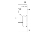
図2は、ユーザが撮影する現実空間を示す図である。図2に示すように、例えば、ユーザUは、ゲーム装置10を把持してCMOSカメラ40の撮影範囲を変更する。CMOSカメラ40は、種々の物体が配置された現実空間50を撮影する。例えば、現実空間50の地面52上には、木54と壁56とが配置される。ユーザが所与の撮影指示操作を行うと、CMOSカメラ40により撮影画像が生成される。
FIG. 2 is a diagram illustrating a real space taken by the user. As shown in FIG. 2, for example, the user U holds the
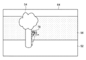
図3は、ゲーム装置10において表示される撮影画像を示す図である。撮影画像60は、第1液晶表示部26aと第2液晶表示部28との何れに表示されるようにしてもよい。本実施形態においては、撮影画像60が第2液晶表示部28に表示される場合を説明する。図3に示すように、撮影画像60には、CMOSカメラ40の撮影範囲内に含まれる現実空間50の物体(例えば、地面52と木54と壁56)が含まれる。
FIG. 3 is a diagram illustrating a captured image displayed on the
また、撮影画像60には、対象領域62が設定される。ユーザは、対象領域62内に現実空間50の所与の物体(被写体)が含まれるように、現実空間50を撮影することを目指す。即ち、対象領域62は、被写体の撮影位置(撮影画像60における表示位置)を、ユーザに案内するためのものである。本実施形態においては、ユーザは、対象領域62内に木54が撮影されるように(位置するように)、CMOSカメラ40の撮影範囲を変更する。
A
本実施形態においては、対象領域62が長方形である場合を説明する。また、本実施形態においては、対象領域62が、撮影画像60の中心点と左端部(例えば、Ys軸)との間の所定位置に配置される場合を説明する。例えば、図3に示すように、撮影画像60の左上端点を原点Osとする平面座標系(スクリーン座標系)の位置P1(X1,0)と、位置P2(X2,Y2)と、を対角線とする長方形内の領域が、対象領域62として設定される(例えば、0<X1<X2,0<Y2)。
In the present embodiment, a case where the
なお、ユーザによる撮影指示操作が行われる前にCMOSカメラ40により生成される撮影前画像において、対象領域62内の画像が、対象領域62外の画像よりも輝度が低く設定されるようにしてもよい。即ち、対象領域62内に撮影される物体と、対象領域62外に撮影される物体と、の表示形態を異ならしめることによって、ユーザに対象領域62が案内されるようにしてもよい。
Note that, in the pre-photographing image generated by the
上記のように、対象領域62内に木54が含まれるようにCMOSカメラ40の撮影範囲が設定された場合、ユーザは、タッチパネル26bや操作キー部36を用いて所与の撮影指示操作を行う。ユーザが撮影指示操作を行うと、撮影画像60が取得される。そして、当該撮影画像60に基づいて、現実空間50を模した仮想空間が主記憶18に構築される。仮想空間には、現実空間50の物体を示すオブジェクトと、現実空間50に合成させる合成対象を示すオブジェクトと、が配置される。
As described above, when the shooting range of the
図4は、主記憶18に構築される仮想空間の一例を示す図である。図4に示すように、仮想空間70には、互いに直交する3軸(Xw軸−Yw軸−Zw軸)が設定される。仮想空間70に配置される各オブジェクト及び仮想カメラ72の位置は、3次元座標によって特定される。
FIG. 4 is a diagram illustrating an example of a virtual space constructed in the
例えば、仮想空間70に配置されるオブジェクトのうち、仮想カメラ72の視野内のオブジェクトが第1液晶表示部26a又は第2液晶表示部28に表示される。仮想カメラ72の視野は、仮想カメラ72に設定される位置、視線方向V、及び画角に基づいて定まる。
For example, among the objects arranged in the
仮想空間70には、対象領域62外に撮影された現実空間50の物体(以降、単に背景という。)を示す背景オブジェクト74と、対象領域62内に撮影された現実空間50の物体(以降、単に被写体という。)を示す被写体オブジェクト76と、が配置される。詳細は後述するが、背景オブジェクト74の表面には、撮影画像60のうち対象領域62外の画像が描かれる。被写体オブジェクト76の表面には、撮影画像60のうち対象領域62内の画像が描かれる。
The
また、仮想空間70には、合成対象を示すオブジェクトであるキャラクタ78が配置される。図4に示すように、キャラクタ78は、背景オブジェクト74と被写体オブジェクト76との間に配置される。例えば、キャラクタ78と仮想カメラ72との間にある被写体オブジェクト76の表面には木54が描かれているので、現実空間50の木54の陰(裏側)からキャラクタ78が現れるような仮想空間画像が表示される。
In the
図5は、仮想空間画像の一例を示す図である。例えば、仮想空間画像64においては、木54の陰(裏側)からキャラクタ78が出現してユーザに駆け寄ってくるように表示制御が行われる。即ち、キャラクタ78が、現実空間50の木54と壁56との間に立っているかのように表示制御が行われる。図4に示すように、仮想カメラ72から見て、キャラクタ78の一部は、被写体オブジェクト76に隠れているので、キャラクタ78のうち、木54に隠れている部位(例えば、キャラクタの下半身)は、仮想空間画像64に表示されない。
FIG. 5 is a diagram illustrating an example of a virtual space image. For example, in the
このように、ゲーム装置10は、リアリティの高い拡張現実をユーザに提供する。更に、本実施形態のゲーム装置10は、例えば、PTAM等に比べて簡易な処理により処理負荷を軽減しつつ、拡張現実のリアリティを高める構成になっている。以下、この技術について詳細に説明する。
As described above, the
[1−3.ゲーム装置において実現される機能]
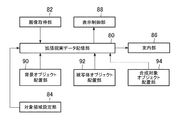
図6は、ゲーム装置10で実現される機能を示す機能ブロック図である。図6に示すように、ゲーム装置10は、拡張現実データ記憶部80、画像取得部82、対象領域設定部84、案内部86、表示制御部88、背景オブジェクト配置部90、被写体オブジェクト配置部92、及び合成対象オブジェクト配置部94を含む。これら各機能は、例えば、制御部14が記憶部16に記憶されたプログラムを実行することによって実現される。
[1-3. Functions realized in game device]
FIG. 6 is a functional block diagram showing functions realized by the
[1−3−1.拡張現実データ記憶部]
拡張現実データ記憶部80は、記憶部16及び主記憶18を主として実現される。拡張現実データ記憶部80は、ユーザに拡張現実を提供するために必要なデータを記憶する。例えば、拡張現実データ記憶部80は、画像取得部82により取得される撮影画像60の画像データを記憶する。
[1-3-1. Augmented reality data storage]
The augmented reality
また、拡張現実データ記憶部80は、仮想空間70の様子を示す仮想空間データを記憶する。仮想空間データには、仮想空間70に配置されたオブジェクトの位置や姿勢を示すデータ、仮想カメラ72の設定内容(例えば、位置、視線方向V、及び画角)を示すデータが格納される。
The augmented reality
また例えば、拡張現実データ記憶部80は、撮影画像60に設定されている対象領域62を識別するためのデータを記憶する。対象領域62を識別するためのデータとしては、撮影画像60に設定されている対象領域62の種別を識別する情報、又は、対象領域62の位置及び形状を示す情報が記憶される。
Further, for example, the augmented reality
例えば、撮影画像60の各画素うち、対象領域62に含まれる画素の位置(例えば、対象領域62の左上の画素と右下の画素の位置)を示す情報が記憶される。対象領域62は、例えば、予め用意された複数の対象領域62の何れかが設定される。
For example, information indicating the positions of the pixels included in the target area 62 (for example, the positions of the upper left pixel and the lower right pixel of the target area 62) among the pixels of the captured
なお、制御部14は、拡張現実データ記憶部80に記憶される各種データを取得する手段として機能する。制御部14は、拡張現実データ記憶部80に記憶される各種データを変更(更新)する手段として機能する。
The
また、拡張現実データ記憶部80に記憶されるデータは、上記の例に限られない。他にも例えば、キャラクタ78の動作を定義したモーションデータや、キャラクタ78の外観を示すテクスチャデータ、被写体オブジェクト76及び背景オブジェクト74にマッピングされる画像のマッピング位置を定義したデータ等が記憶されていてもよい。
The data stored in the augmented reality
他にも例えば、対象領域62の種別を識別する情報と、対象領域62の形状及び位置を示す情報と、が関連付けられて記憶されるようにしてもよい。この場合、例えば、ユーザにより指定された対象領域62が撮影画像60に設定される。例えば、複数の対象領域62のうち、ユーザにより指定された種別の対象領域62に関連付けられた形状及び位置の対象領域62が撮影画像60に設定される。
In addition, for example, information for identifying the type of the
[1−3−2.画像取得部]
画像取得部82は、制御部14を主として実現される。画像取得部82は、現実空間50を撮影する撮影手段(例えば、CMOSカメラ40)から現実空間50の撮影画像60を取得する。画像取得部82は、CMOSカメラ40の検出信号に基づいて生成される撮影画像60を取得する。
[1-3-2. Image acquisition unit]
The
CMOSカメラ40の撮影範囲は、ユーザの操作により変化する。例えば、ユーザがCMOSカメラ40の姿勢を変化させて、CMOSカメラ40の位置及び視線方向Vを変化させることによって、CMOSカメラ40の撮影範囲を変化させる。
The shooting range of the
例えば、画像取得部82は、ユーザにより撮影指示操作が行われた場合に、撮影手段(例えば、CMOSカメラ40)から撮影画像60を取得する。本実施形態においては、画像取得部82は、対象領域62がユーザに案内された後、ユーザにより撮影指示操作が行われた場合、撮影手段(例えば、CMOSカメラ40)から撮影画像60を取得する場合を説明する。
For example, the
[1−3−3.対象領域設定部]
対象領域設定部84は、制御部14を主として実現される。対象領域設定部84は、撮影画像60に対象領域62を設定する。対象領域設定部84は、拡張現実データ記憶部80に記憶された対象領域82を識別する情報に基づいて、撮影画像60に対象領域62を設定する。例えば、対象領域設定部84は、複数の対象領域82のうち、ユーザに指定された対象領域82を、撮影画像60に設定する。対象領域設定部84により設定された対象領域62を示す情報は、拡張現実データ記憶部80に記憶される。
[1-3-3. Target area setting section]
The target
[1−3−4.案内部]
案内部86は、制御部14及び第1液晶表示部26a又は第2液晶表示部28を主として実現される。案内部86は、ユーザによる撮影指示操作が行われる前において撮影手段(例えば、CMOSカメラ40)から取得される、現実空間50を示す撮影前画像を表示手段(例えば、第2液晶表示部28)に表示させ、撮影前画像において、撮影画像60に設定される対象領域62をユーザに案内する。
[1-3-4. Guide section]
The
案内部86は、例えば、第2液晶表示部28に表示される撮影前画像のうち、対象領域62内の画像の表示形態と、対象領域62外の画像の表示形態と、を異ならしめることによって、ユーザに対象領域62を案内する。例えば、案内部86は、撮影前画像のうち、対象領域62内の画像又は対象領域62外の画像に所与のエフェクト処理を施すことによって、ユーザに対象領域62を案内する。
For example, the
なお、対象領域62は、他の方法によってユーザに案内されるようにしてもよい。他にも例えば、対象領域62は、所与の指標が表示されることによってユーザに案内されるようにしてもよいし、所与の音声が出力されることによってユーザに案内されるようにしてもよい。
The
[1−3−5.表示制御部]
表示制御部88は、制御部14を主として実現される。表示制御部88は、仮想空間70を所与の視点(例えば、仮想カメラ72)から見た様子を示す仮想空間画像64を表示手段(例えば、第2液晶表示部28)に表示させる。
[1-3-5. Display control unit]
The
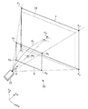
図7は、仮想空間画像64の表示方法を説明するための図である。図7に示すように、仮想空間70のうち、仮想カメラ72の視野を所与のニアクリップNとファークリップFで切り取った視錘台内の空間が、仮想空間画像64に表示される。例えば、仮想カメラ72の視野のうちニアクリップNとファークリップFとで挟まれた空間内のオブジェクトに、所与の座標変換処理が実行されることによって、仮想空間画像64が表示される。
FIG. 7 is a diagram for explaining a display method of the
仮想カメラ72とニアクリップN及びファークリップFとの位置関係は、予め設定されている。例えば、ニアクリップNの中心点N0及び端点N1〜N4と仮想カメラ72との位置関係を示すデータ(例えば、仮想カメラ72とニアクリップNとの距離)、及び、ファークリップFの中心点F0及び端点F1〜F4と仮想カメラ72との位置関係を示すデータ(例えば、仮想カメラ72とファークリップFとの距離)が予め記憶されている。
The positional relationship between the
[1−3−6.背景オブジェクト配置部]
背景オブジェクト配置部90は、制御部14を主として実現される。背景オブジェクト配置部90は、撮影画像60の対象領域62外に撮影された背景(例えば、地面52や壁56)を示す背景オブジェクト74を仮想空間70に配置する。背景オブジェクト74は、仮想カメラ72の視野内の所定位置に配置される。例えば、仮想空間画像64における背景オブジェクト74の表示位置と、撮影画像60における対象領域62外の位置と、が対応するように、背景オブジェクト74が配置される。
[1-3-6. Background object placement section]
The background
本実施形態においては、背景オブジェクト74は、例えば、仮想カメラ72の視野を仮想カメラ72の視線方向Vに略直交する平面で切断した切断面に基づいて生成される場合を説明する。例えば、図7に示すように、仮想カメラ72の視錘台を、仮想カメラ72の視線方向Vに垂直な平面(視線方向Vを垂線方向とする平面)で切り取った切断面と、背景オブジェクト74の表面と、は略一致する。
In the present embodiment, for example, a case will be described in which the
例えば、背景オブジェクト74は、仮想カメラ72との距離が距離D1(例えば、仮想カメラ72とニアクリップNとの距離<距離D1≦仮想カメラ72とファークリップFとの距離)となる位置に配置される。例えば、背景オブジェクト74の表面は、ニアクリップN及びファークリップFと平行になるように配置される。
For example, the
上記のように配置される背景オブジェクト74の表面には、撮影画像60のうち対象領域62外の画像(以降、背景画像60aという。)に基づいて、現実空間50の様子が描画される。
On the surface of the
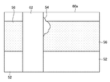
図8は、背景画像60aの一例を示す図である。図8に示すように、背景画像60aは、撮影画像60から対象領域62内の画像(以降、被写体画像60bという。)を除いた画像である。別の言い方をすれば、背景画像60aは、撮影画像60と被写体画像60bとの差分画像である。
FIG. 8 is a diagram illustrating an example of the
背景オブジェクト74の各点は、背景画像60aの各点と関連付けられており、背景オブジェクト74の表面に背景画像60aがマッピングされる。即ち、背景画像60aは、背景オブジェクト74のテクスチャとして使用される。別の言い方をすれば、背景オブジェクト74には、背景画像60aに基づいて、現実空間50の背景が描画される。
Each point of the
上記のように、背景オブジェクト74が、背景画像60aと同じように仮想空間画像64に表示されるように、背景オブジェクト74の形状及び位置が決定される。別の言い方をすれば、CMOSカメラ40と背景画像60aに撮影された現実空間50の背景との位置関係と、仮想カメラ72と背景オブジェクト74に描かれた現実空間50の背景との位置関係と、が対応するように、背景オブジェクト74が配置される。
As described above, the shape and position of the
[1−3−7.被写体オブジェクト配置部]
被写体オブジェクト配置部92は、制御部14を主として実現される。被写体オブジェクト配置部92は、撮影画像60の対象領域62内に撮影された被写体を示す被写体オブジェクト76を仮想空間70に配置する手段である。被写体オブジェクト配置部92は、仮想空間画像64において被写体オブジェクト76が背景オブジェクト74に重畳表示される位置と、撮影画像60における対象領域62の位置と、が対応するように、被写体オブジェクト76を、視点(例えば、仮想カメラ72)と背景オブジェクト74との間に配置する。
[1-3-7. Subject object placement section]
The subject
図9は、被写体オブジェクト76の配置方法を説明するための図である。図9に示すように、例えば、背景オブジェクト74の表面のうち撮影画像60の対象領域62に対応する領域(対象領域62の部分がマッピングされた領域)を底面とし仮想カメラ72の位置を頂点とする錐体Cを、仮想カメラ72の視線方向Vに略直交する平面で切断した切断面に基づいて生成される。
FIG. 9 is a diagram for explaining a method of arranging the
即ち、背景オブジェクト74の表面に背景画像60aがマッピングされた場合の対象領域62を底面とし、仮想カメラ72の位置を頂点とする錐体Cを、仮想カメラ72の視線方向Vに垂直な平面(ただし、ニアクリップNと背景オブジェクト74との間の平面)で切り取った切断面と、被写体オブジェクト76の表面と、が略一致するように、被写体オブジェクト76の形状及び位置が決定される。
That is, the cone C having the
被写体オブジェクト配置部92は、被写体画像60bに基づいて、上記のように配置される被写体オブジェクト76の表面に、現実空間50の様子を描画する。
The subject
図10は、被写体画像60bの一例を示す図である。図10に示すように、被写体画像60bは、撮影画像60から対象領域62の画素が切り出されることによって生成される画像である。
FIG. 10 is a diagram illustrating an example of the
例えば、被写体オブジェクト76の各点は、被写体画像60bの各点と関連付けられており、被写体オブジェクト76の表面に被写体画像60bがマッピングされる。即ち、被写体画像60bは、被写体オブジェクト76のテクスチャとして使用される。別の言い方をすれば、被写体オブジェクト76には、被写体画像60bに基づいて、対象領域62内に撮影された現実空間の被写体が描画される。
For example, each point of the
上記のように、例えば、仮想空間画像64における被写体オブジェクト76の表示位置と、撮影画像60における対象領域62の位置と、が対応するように、被写体オブジェクト76の位置が設定される。別の言い方をすれば、撮影画像60の中心点と対象領域62との位置関係と、仮想カメラ72の注視点と被写体オブジェクト76との位置関係と、が対応するように、被写体オブジェクト76が配置される。なお、背景オブジェクト74と被写体オブジェクト76との位置関係は、撮影画像60と対象領域62との位置関係に対応しているともいえる。
As described above, for example, the position of the
[1−3−8.合成対象オブジェクト配置部]
合成対象オブジェクト配置部94は、仮想空間画像64において現実空間50と合成して表示させる合成対象を示す合成対象オブジェクト(例えば、キャラクタ78)を、背景オブジェクト74と被写体オブジェクト76との間に配置する。
[1-3-8. Compositing target object placement section]
The compositing target
本実施形態においては、キャラクタ78は、被写体オブジェクト76よりも仮想カメラ72から遠い位置に配置される。つまり、キャラクタ78と仮想カメラ72との間隔は、被写体オブジェクト76と仮想カメラ72との間隔よりも長い。別の言い方をすれば、仮想カメラ72からキャラクタ78を見た場合にキャラクタ78の一部が被写体オブジェクト76に隠れるように、キャラクタ78と仮想カメラ72との間に、被写体オブジェクト76が配置される。
In the present embodiment, the
キャラクタ78は、例えば、所与のモーションデータに定義された動作をする。例えば、キャラクタ78は、仮想空間70内を移動する。例えば、キャラクタ78は、仮想カメラ72に向かって移動したり、被写体オブジェクト76の周囲を回るように移動する。他にも例えば、キャラクタ78は、仮想カメラ72の視野外に出たり視野内に戻ったりするようにしてもよい。
The
表示制御部88は、仮想空間画像64において、合成対象オブジェクト(例えば、キャラクタ78)を背景オブジェクト74に重畳表示させ、かつ、被写体オブジェクト76を合成対象オブジェクト(例えば、キャラクタ78)に重畳表示させる。
In the
表示制御部88は、キャラクタ78が、撮影画像60の対象領域62内に撮影された被写体と、撮影画像60の対象領域62外に撮影された背景と、の間に位置しているように、仮想空間画像64の表示制御を行う。即ち、表示制御部88は、キャラクタ78の一部が、被写体オブジェクト76に隠れるように表示制御を行う。
The
[1−4.ゲーム装置において実行される処理]
次に、ゲーム装置10が実行する処理について説明する。図11及び図12は、ゲーム装置10が実行する処理のうちの、本発明に関連する処理を主に示すフロー図である。制御部14は、例えば、記憶部16及びゲームメモリカード44に記憶されるプログラムに従って、図11及び図12に示す処理を実行する。図11及び図12に示す処理は、ユーザにより所与の操作が行われた場合に実行される。例えば、図示しないメニュー画面から、拡張現実が提供されるためのボタンが選択された場合に、以下に説明する処理が実行される。
[1-4. Processing executed in game device]
Next, processing executed by the
図11に示すように、まず、制御部14は、CMOSカメラ40を起動して、CMOSカメラ40の検出信号に基づいて生成される撮影前画像を第2液晶表示部28に表示させる(S1)。制御部14は、記憶部16又はゲームメモリカード44に記憶された対象領域62の位置及び形状を示すデータを参照し、撮影前画像のうち、対象領域62内の画素の輝度を対象領域62外の画素の輝度よりも低く表示させることによって、対象領域62をユーザに案内する(S2)。なお、S2において案内される対象領域62は、撮影画像60に設定される対象領域62であり、例えば、予めユーザに指定された対象領域62が案内されるようにしてもよい。
As shown in FIG. 11, first, the
制御部14は、ユーザから撮影指示操作が入力されたか否かを判定する(S3)。撮影指示操作が入力されない場合(S3;N)、処理はS1に戻る。この場合、ユーザはゲーム装置10の姿勢を変更することによって、CMOSカメラ40の撮影範囲を変更する。例えば、ユーザは、対象領域62内に木54が含まれるように撮影範囲を変更する。
The
撮影指示操作が入力された場合(S3;Y)、制御部14は、撮影画像60の画像データを一時的に主記憶18に記憶させる(S4)。即ち、ユーザにより撮影指示操作が入力された場合にCMOSカメラ40の検出信号に基づいて生成された撮影画像60の画像データが、主記憶18に記憶される。当該生成された撮影画像60には、S2において案内された対象領域62が設定される。
When the photographing instruction operation is input (S3; Y), the
制御部14は、主記憶18に仮想空間70を構築する(S5)。S5においては、例えば、3軸が設定されて、仮想カメラ72が所与の位置に配置される。仮想カメラ72の位置、視線方向V、及び画角は、予め定められた値が設定されるようにしてもよい。
The
制御部14は、背景オブジェクト74を、仮想カメラ72の視野内の所与の位置に配置する(S6)。例えば、仮想カメラ72の視錘台を、ニアクリップNとファークリップFに平行な平面で切断した切断面に基づいて、背景オブジェクト74が配置される。
The
制御部14は、主記憶18に記憶された撮影画像60のうち、対象領域62外の背景画像60aを抽出する(S7)。例えば、対象領域62の位置及び形状を示す情報が参照され、撮影画像60から対象領域62外の背景画像60aが切り出される。S7において抽出された背景画像60aを示す画像データは、主記憶18に一時的に記憶される。
The
なお、撮影画像60がそのまま背景オブジェクト74にマッピングされたとしても、対象領域62がマッピングされている箇所を仮想カメラ72から見た場合、当該箇所は被写体オブジェクト76に隠れて表示されないので、S7においては、撮影画像60をそのまま背景オブジェクト74にマッピングするようにしてもよい。
Even if the captured
制御部14は、S6において配置された背景オブジェクト74に、S7において抽出された背景画像60aをマッピングする(S8)。S8においては、背景画像60aのマッピング位置を示すデータが参照されることによって、背景画像60aのマッピングが行われる。
The
図12に移り、制御部14は、被写体オブジェクト76を、仮想カメラ72と背景オブジェクト74との間に配置する(S9)。S9においては、例えば、背景オブジェクト74に描かれた対象領域62を底面とし、仮想カメラ72を頂点とする錐体の切断面に基づいて、被写体オブジェクト76が配置される。別の言い方をすれば、仮想カメラ72を基準(光源)として被写体オブジェクト76を射影した場合、背景オブジェクト74の表面に表れる被写体オブジェクト76の影と、背景オブジェクト74の表面における対象領域62と、が略一致するように、被写体オブジェクト76が配置される。
Moving to FIG. 12, the
制御部14は、主記憶18に記憶された撮影画像60のうち、対象領域62内の被写体画像60bを抽出する(S10)。例えば、対象領域62の位置及び形状を示す情報が参照され、撮影画像60から対象領域62内の被写体画像60bが切り出される。S10において抽出された被写体画像60bを示す画像データは、主記憶18に一時的に記憶される。
The
制御部14は、S9において配置された被写体オブジェクト76に、S10において抽出された被写体画像60bをマッピングする(S11)。S11においては、被写体画像60bのマッピング位置を示すデータが参照されることによって、被写体画像60bのマッピングが行われる。
The
制御部14は、モーションデータを参照し、キャラクタ78を仮想空間70に配置する(S12)。例えば、キャラクタ78は、被写体オブジェクト76と背景オブジェクト74との間に配置される。キャラクタ78は、モーションデータに基づいて所与の動作をする。
The
制御部14は、仮想カメラ72から仮想空間70を見た様子を示す仮想空間画像64を第2液晶表示部28に表示させる(S13)。S13においては、例えば、キャラクタ78が木54の陰から表れるように仮想空間画像64の表示制御が実行される。
The
制御部14は、終了条件を満たすか否かを判定する(S14)。終了条件は、本処理を終了させるために予め定められた条件であればよく、例えば、モーションデータの再生が終了したか否かを示す条件である。
The
終了条件を満たす場合(S14;Y)、制御部14は、本処理を終了する。終了条件を満たさない場合(S14;N)、処理はS12に戻り、モーションデータの再生が継続される。
When the end condition is satisfied (S14; Y), the
以上説明したゲーム装置10によれば、撮影画像60に設定される対象領域62に基づいて、架空のキャラクタ78が現実空間50を自在に移動するような仮想空間画像64を表示させることができるので、ユーザが感じるリアリティが向上する。例えば、ユーザは、現実空間50においてキャラクタ78と一緒に遊んでいるかのような感覚を得ることができる。
According to the
また、背景オブジェクト74と被写体オブジェクト76とを用いることによって、現実空間50を模した仮想空間70を疑似的に生成することができるので、例えば、PTAM技術等に比べて簡易な処理内容で、木54と壁56の間からキャラクタ78が表れるような表示制御処理を実行することができる。
Further, by using the
したがって、ゲーム装置10の処理負荷を軽減しつつ、リアリティの高い拡張現実をユーザに提供することができる。また、対象領域62をユーザに案内してからユーザに撮影指示操作を行わせることによって、ユーザは、対象領域62に被写体を撮影することができる。ユーザは、案内された対象領域62に合わせて被写体を撮影するだけでよいので、特段の専門知識を要することなく手軽に拡張現実を体験することができる。
Therefore, it is possible to provide the user with augmented reality with high reality while reducing the processing load of the
[2.変形例]
なお、本発明は、以上に説明した実施の形態に限定されるものではない。本発明の趣旨を逸脱しない範囲で、適宜変更可能である。
[2. Modified example]
The present invention is not limited to the embodiment described above. Modifications can be made as appropriate without departing from the spirit of the present invention.
(1)例えば、現実空間50に配置されている木54には、比較的太いものもあれば細いものもある。したがって、対象領域62に木54が収まりきらない場合もあり、対象領域62の幅が木54の幅よりも広すぎる場合もある。そこで、ユーザの操作によって対象領域62の形状又は位置が変更されるようにしてもよい。例えば、ユーザは、予め用意された複数の対象領域62の中から、撮影画像60に設定する対象領域62を選択するようにしてもよいし、撮影画像60に設定されている対象領域62の形状又は位置の変更操作を行ってもよい。
(1) For example, some
変形例(1)のゲーム装置10は、撮影画像60に設定される対象領域62の形状又は位置の変更指示操作をユーザが行うための手段を含む。当該手段は、タッチパネル26b又は操作キー部36を主として実現される。例えば、制御部14が、所与の操作信号を取得することによって、対象領域62の変更指示操作が検出される。例えば、対象領域62の変更指示操作は、複数の対象領域62の何れかをユーザが指定する操作、又は、現在設定されている対象領域62の形状又は位置の変更をユーザが指示する操作である。
The
また、ゲーム装置10は、ユーザにより変更指示操作が行われた場合、当該変更指示操作に基づいて対象領域62を変更する手段を含む。当該手段は、制御部14を主として実現される。例えば、複数の対象領域62のうちユーザにより指定された対象領域62が撮影画像60に設定される、又は、ユーザによる変更指示操作に基づいて対象領域62の形状又は位置が変更される。
Further, the
例えば、変形例(1)の拡張現実データ記憶部80は、予め用意された対象領域62の種別と、当該対象領域62の形状又は位置を示すデータと、を関連付けて記憶する。又は、拡張現実データ記憶部80は、ユーザによる変更指示操作と、対象領域62の形状又は位置の変更方法を示すデータと、を関連付けて記憶する。ユーザにより変更指示操作が行われた場合、拡張現実データ記憶部80の記憶内容が参照されることによって、変更後の対象領域62の形状又は位置が特定される。
For example, the augmented reality
図13は、ユーザにより形状及び位置が変更された対象領域62を示す図である。例えば、図3に示す長方形の対象領域62が、図13に示すような楕円形の対象領域62に変更される。この状態では、例えば、ユーザは、現実空間50に配置された机58を対象領域62内に撮影することを目指す。ユーザにより、対象領域62内に机58が撮影されると、仮想空間70には、楕円形の対象領域62に対応する被写体オブジェクト76が配置される。
FIG. 13 is a diagram illustrating the
変形例(1)の被写体オブジェクト配置部92は、変更された対象領域62の形状又は位置に基づいて、被写体オブジェクト76の形状又は位置を決定する。被写体オブジェクト76の設定方法は、実施形態と同様である。即ち、仮想空間画像64における被写体オブジェクト76の形状及び位置が、撮影画像60における対象領域62の形状及び位置に対応するように、被写体オブジェクト76の形状又は位置が決定される。例えば、背景オブジェクト74の表面における対象領域62を底面とし、仮想カメラ72を頂点とする錐体(上記の場合は楕円錐)を、仮想カメラ72の視線方向Vと垂直な平面で切断した切断面に基づいて、被写体オブジェクト76が設定される。
The subject
また、変形例(1)の合成対象オブジェクト配置部94は、視点(例えば、仮想カメラ72)から見て、合成対象オブジェクト(例えば、キャラクタ78)の全部又は一部が、被写体オブジェクト76に隠れるように、合成対象オブジェクトの位置又は動作を決定する。
In addition, the compositing target
例えば、キャラクタ78が、仮想カメラ72から見て、背景オブジェクト74と被写体オブジェクト76との間に配置されるように、キャラクタ78の位置又は動作が決定される。例えば、モーションデータの再生開始時のキャラクタ78の位置が、背景オブジェクト74と被写体オブジェクト76との間になるように、キャラクタ78の位置が決定差される。また例えば、複数のモーションデータを用意しておき、これら複数のモーションデータのうち、キャラクタ78の位置が背景オブジェクト74と被写体オブジェクト76との間になる動作を定義したモーションデータが抽出され、当該モーションデータが再生される。
For example, the position or action of the
変形例(1)によれば、ユーザは、現実空間50に配置された物体の配置状況に応じて、対象領域62を変更することができる。例えば、木54が対象領域62に対して細い場合には、対象領域62の幅を細くすることができるので、ゲーム装置10は、現実空間50に応じた最適な拡張現実をユーザに提供することができる。
According to the modification example (1), the user can change the
(2)また例えば、仮想カメラ72から見てキャラクタ78が被写体オブジェクト76に隠れている場合、当該隠れている箇所の一部分のみを仮想空間画像64に表示させるようにしてもよい。
(2) For example, when the
図14は、変形例(2)において表示される仮想空間画像64の一例を示す図である。図14に示すように、キャラクタ78が、ユーザから見て机58の奥側に座っているように、仮想空間画像64が表示される。キャラクタ78のうち、机58に隠れている部分(例えば、キャラクタ78の胴体)は表示されない。一方、キャラクタ78のうち、机58に隠れていない部分(例えば、キャラクタ78の足)は、表示される。
FIG. 14 is a diagram illustrating an example of the
上記のような表示制御を実現するために、変形例(2)における被写体オブジェクト76は、半透明ポリゴンを含んで構成される。半透明ポリゴンは、透過度(いわゆるアルファ値)が設定され、例えば、表面に描かれたテクスチャを透過させる。
In order to realize the display control as described above, the
例えば、表示制御部88は、被写体オブジェクト76のうち、対象領域62内の所定領域(例えば、下半分)に撮影された部分を示す半透明ポリゴンの透過度を透過させる。対象領域62の所定領域は、予め定められた対象領域62の一部分であり、例えば、サービス提供者が、被写体ではなく背景が撮影されると想定する領域である。例えば、対象領域62の所定領域は、机58ではなく、地面52が撮影されると想定される領域である。
For example, the
図15は、変形例(2)における仮想空間70を示す図である。例えば、図15に示すように、仮想空間70には、楕円形の被写体オブジェクト76が配置される。キャラクタ78は、座位姿勢で配置される。仮想カメラ72からキャラクタ78を見た場合、キャラクタ78の首から下の部位は、被写体オブジェクト76に隠れる。即ち、被写体オブジェクト76が半透明ポリゴンでない場合、被写体オブジェクト76は透過しないので、キャラクタ78の首から下の部位は、仮想空間画像64に表示されない。
FIG. 15 is a diagram illustrating the
そこで、変形例(2)の表示制御部88は、合成対象オブジェクト(例えば、キャラクタ78)のうち、視点(例えば、仮想カメラ72)から見て透過された半透明ポリゴンが重畳する部分を、仮想空間画像64において表示させる。図15に示す場合、楕円形の被写体オブジェクト76の上側は透過しないように設定され、下側(図15に示す斜線領域76a)は透過するように設定される。被写体オブジェクト76に設定される透過度を示す情報は、予め拡張現実データ記憶部80に記憶されるようにしてもよいし、ユーザの操作入力に基づいて設定されるようにしてもよい。
Therefore, the
変形例(2)によれば、例えば、図15に示すように、机58の奥に座るキャラクタ78の足だけが見えるような表示制御を行うことができるので、拡張現実のリアリティを更に向上させることができる。
According to the modification (2), for example, as shown in FIG. 15, display control can be performed so that only the foot of the
(3)また例えば、実施形態においては、長方形の対象領域62が設定される場合を説明したが、変形例(1)及び変形例(2)のように、他の対象領域62が撮影画像60に設定されるようにしてもよい。この場合、キャラクタ78は、撮影画像60に設定された対象領域62に基づいて生成される仮想空間70に応じた動作をするようにしてもよい。
(3) For example, in the embodiment, the case where the
変形例(3)の拡張現実データ記憶部80は、仮想空間70(例えば、対象領域62の種別、形状、又は位置を識別する情報)と、合成対象オブジェクトの動作を定義したモーションデータと、を関連付けて記憶する場合を説明する。即ち、撮影画像60に設定された対象領域62に基づいて生成される仮想空間70に応じてキャラクタ78が異なる動作をするように、モーションデータが定義されている。
The augmented reality
図16は、モーションデータのデータ格納例を示す図である。図16に示すように、仮想空間70を識別する情報としては、対象領域62の種別を示す情報や、対象領域62の位置又は形状を示す情報が格納される。図16に示す複数の対象領域62の何れかが、撮影画像60に設定される。
FIG. 16 is a diagram illustrating a data storage example of motion data. As shown in FIG. 16, information indicating the type of the
図16に示すモーションデータは、キャラクタ78の時系列的な位置変化を定義したデータである。例えば、モーションデータとしては、キャラクタ78のポリゴンの頂点位置の変化を定義したデータが格納される。具体的には、キャラクタ78に設定されるスケルトンの位置変化と、当該変化するスケルトンの位置とポリゴンの頂点位置との位置関係と、を示すデータが、モーションデータとして格納される。
The motion data shown in FIG. 16 is data defining time-series position changes of the
例えば、縦長の対象領域62に基づいて生成される仮想空間70に関連付けられたモーションデータは、被写体の陰からキャラクタ78が駆け寄ってくる動作が定義される。また例えば、横長の対象領域62に基づいて生成される仮想空間70に関連付けられたモーションデータは、被写体の奥にキャラクタ78が腰掛ける動作が定義される。
For example, the motion data associated with the
変形例(3)の合成対象オブジェクト配置部94は、表示制御部88により生成された仮想空間70に関連付けられたモーションデータに基づいて、合成対象オブジェクト(例えば、キャラクタ78)を仮想空間70において動作させる。
The compositing target
例えば、拡張現実データ記憶部80の記憶内容が参照され、撮影画像60に設定された対象領域62を示す情報が参照される。例えば、撮影画像60に設定されている対象領域62の種別が特定される。そして、撮影画像60に設定されている対象領域62に基づいて生成される仮想空間70に関連付けられたモーションデータに基づいて、仮想空間70内のキャラクタ78を動作させる。モーションデータが再生されることによって、仮想空間70内でキャラクタ78が動作する。
For example, the contents stored in the augmented reality
変形例(3)によれば、仮想空間70に応じた動作をキャラクタ78に行わせることができる。したがって、多種多様な拡張現実をユーザに提供することができる。
According to the modification (3), the
(4)また例えば、対象領域62に撮影されるべき被写体が、ユーザに案内されるようにしてもよい。例えば、ユーザが対象領域62に木54を撮影すべき旨が案内されるようにしてもよい。この場合、対象領域62に撮影されるべき被写体に応じた動作を、キャラクタ78が行うようにしてもよい。即ち、対象領域62に木54が撮影されるべき場合と、対象領域62に机58が撮影されるべき場合と、でキャラクタ78の動作が異なるようにしてもよい。
(4) Further, for example, a subject to be photographed in the
変形例(4)のゲーム装置10は、対象領域62に撮影されるべき被写体をユーザに案内する手段を含む。例えば、当該手段は、案内部86によって実現される。案内部86は、撮影前画像に所与の指標を重畳させることによって、被写体をユーザに案内する。他にも例えば、音声によって被写体をユーザに案内するようにしてもよい。案内部86が案内すべき被写体は、対象領域62に応じて変化するようにしてもよい。また、案内部86が案内している被写体を示す情報が、拡張現実データ記憶部80に記憶されるようにしてもよい。
The
変形例(4)の拡張現実データ記憶部80は、被写体と、合成対象オブジェクトの動作を定義したモーションデータと、を関連付けて記憶する。被写体は、ユーザに案内される被写体であり、サービス提供者が予め定めた物体である。被写体に応じて対象領域62の形状や位置が設定されているようにしてもよい。
The augmented reality
図17は、被写体とモーションデータとの関連付けを示す図である。図17に示すように、被写体を識別するための情報と、モーションデータと、が関連付けられて記憶される。図17に示すデータにおいて定義された被写体の何れかが、ユーザに案内される。 FIG. 17 is a diagram illustrating an association between a subject and motion data. As shown in FIG. 17, information for identifying a subject and motion data are stored in association with each other. Any of the subjects defined in the data shown in FIG. 17 is guided to the user.
変形例(4)の合成対象オブジェクト配置部94は、ユーザに案内された被写体に関連付けられたモーションデータに基づいて、合成対象オブジェクト(例えば、キャラクタ78)を仮想空間70において動作させる。例えば、合成対象オブジェクト配置部94は、拡張現実データ記憶部80の記憶内容を参照し、案内部86によりユーザに案内されている被写体を特定する。当該特定された被写体に関連付けられたモーションデータに基づいて、キャラクタ78が仮想空間70で動作する。
The compositing target
変形例(4)によれば、対象領域62に撮影されるべき被写体に応じた動作をキャラクタ78に行わせることができる。
According to the modification (4), the
(5)また例えば、撮影画像60に複数の対象領域62が設定されるようにしてもよい。例えば、撮影画像60に2つの対象領域62が設定される場合、それぞれの対象領域62内に撮影された現実空間50の物体を示す被写体オブジェクト76が、仮想空間70に配置される。即ち、複数の被写体オブジェクト76が、仮想空間70に配置される。
(5) For example, a plurality of
なお、これら複数の被写体オブジェクト76の各々と、仮想カメラ72と、の距離は、互いに異なっていてもよい。即ち、仮想カメラ72から比較的離れた位置に配置されている被写体オブジェクト76があってもよいし、当該被写体オブジェクト76よりも仮想カメラ72に近い被写体オブジェクト76があってもよい。
Note that the distance between each of the plurality of
また例えば、撮影画像60に複数の対象領域62が設定される場合、当該複数の対象領域62の組み合わせに応じてキャラクタ78の動作が異なるようにしてもよい。この場合、例えば、対象領域62の組み合わせと、モーションデータと、が関連付けられて記憶されるようにしてもよい。合成対象オブジェクト配置部94は、撮影画像60に設定されている対象領域62の組み合わせに関連付けられたモーションデータに基づいて、キャラクタ78を動作させる。
Further, for example, when a plurality of
(6)また例えば、被写体オブジェクト76を配置する位置をユーザが指定できるようにしてもよい。例えば、仮想カメラ72と被写体オブジェクト76との距離をユーザが指定できるようにしてもよい。別の言い方をすれば、錐体Cの切断面の位置をユーザが指定できるようにしてもよい。このようにすることによって、現実空間50に配置された被写体の奥行き(被写体とCMOSカメラ40との距離)をユーザが指定することができる。
(6) Further, for example, the user may be allowed to specify the position where the
(7)また例えば、キャラクタ78がモーションデータに基づいて動作する場合を説明したが、キャラクタ78は、ユーザによる操作に基づいて仮想空間70内を動作するようにしてもよい。例えば、タッチパネル26b又は操作キー部36の検出信号に基づいて、キャラクタ78の位置や姿勢、移動方向が変更されるようにしてもよい。このようにすることによって、ユーザは、自分の操作に応じて、キャラクタ78が現実空間50に配置された物体に隠れたり出現したりする様子を味わうことができる。
(7) For example, although the case where the
(8)また例えば、ユーザの操作に応じて、仮想空間70に所与のオブジェクトを生成するようにしてもよい。例えば、ユーザが所与の操作を行うと、仮想空間70に雪玉を示すオブジェクトが生成される。当該オブジェクトは、ユーザの操作に応じて、仮想空間70を移動する。例えば、仮想空間70内を動き回るキャラクタ78に当該オブジェクトを接触させることをユーザが目指すゲーム(例えば、雪合戦ゲーム)が実行されるようにしてもよい。
(8) Further, for example, a given object may be generated in the
例えば、キャラクタ78が被写体オブジェクト76と背景オブジェクト74との間に位置する場合には、雪玉を示すオブジェクトは被写体オブジェクト76に接触する。したがって、ユーザは、キャラクタ78が現実空間50の木54に隠れて、自分が投げた雪玉をやり過ごすような感覚を味わうことができる。
For example, when the
(9)また例えば、実施形態においては、撮影画像60が静止画である場合を説明したが、連続撮影された撮影画像60からなる動画に基づいて、仮想空間70が生成されるようにしてもよい。また例えば、ユーザが撮影開始操作を行った場合のCMOSカメラ40の位置及び姿勢が記憶されるようにしてもよい。この場合、センサ部42により検出されるCMOSカメラ40の位置及び姿勢の変化に応じて、仮想カメラ72の位置及び姿勢が制御されるようにしてもよい。
(9) For example, in the embodiment, the case where the photographed
(10)また例えば、対象領域62がユーザに案内された後に、ユーザが撮影指示操作を行う場合を説明したが、撮影画像60が撮影された後に、ユーザによって対象領域62が設定されるようにしてもよい。この場合、案内部86は、ゲーム装置10において実現されないようにしてもよい。例えば、ユーザは、撮影画像60に設定したい対象領域62をタッチペン等を用いて囲うことによって、対象領域62を設定する。
(10) For example, although the case where the user performs a shooting instruction operation after the
(11)また例えば、実施形態においては、背景オブジェクト74及び被写体オブジェクト76が動的に生成される場合を説明したが、背景オブジェクト74の形状及び位置と、被写体オブジェクト76の形状及び位置と、を定義したデータが予め記憶されていてもよい。この場合、当該データは、対象領域62毎に記憶されている。ユーザにより撮影画像60が撮影された場合、当該撮影時に設定されている対象領域62に関連付けられたデータに基づいて、背景オブジェクト74及び被写体オブジェクト76が仮想空間70に配置される。
(11) For example, in the embodiment, the case where the
(12)また、合成対象オブジェクトは、キャラクタ78に限られない。合成対象オブジェクトは、現実空間50に合成させる合成対象を示すオブジェクトであればよく、他にも例えば、現実空間50にはない架空の物体(例えば、架空の岩)が、合成対象オブジェクトとして仮想空間70に配置されるようにしてもよい。
(12) Further, the compositing target object is not limited to the
(13)また例えば、本発明は、実施形態や変形例において説明したゲーム装置10以外の画像処理装置にも適用することができる。例えば、画像処理装置が携帯電話機によって実現される場合には、携帯電話機に備えられたカメラにより生成される撮影画像に基づいて拡張現実がユーザに提供されるようにしてもよい。
(13) Further, for example, the present invention can also be applied to an image processing apparatus other than the
10 ゲーム装置、12 携帯ゲーム機、14 制御部、16 記憶部、18 主記憶、20 画像処理部、22 入出力処理部、24 バス、26 タッチスクリーン、26a 第1液晶表示部、26b タッチパネル、28 第2液晶表示部、30 メモリカードスロット、32 音声処理部、34 音声出力部、36 操作キー部、38 通信インタフェース、40 CMOSカメラ、42 センサ部、44 ゲームメモリカード、50 現実空間、52 地面、54 木、56 壁、58 机、60 撮影画像、60a 背景画像、60b 被写体画像、62 対象領域、64 仮想空間画像、70 仮想空間、72 仮想カメラ、74 背景オブジェクト、76 被写体オブジェクト、78 キャラクタ、80 拡張現実データ記憶部、82 画像取得部、84 対象領域設定部、86 案内部、88 表示制御部、90 背景オブジェクト配置部、92 被写体オブジェクト配置部、94 合成対象オブジェクト配置部、N ニアクリップ、F ファークリップ。
DESCRIPTION OF
Claims (9)
仮想3次元空間に配置されたオブジェクトに所与の座標変換処理を実行することによって、前記仮想3次元空間を所与の視点から見た様子を示す仮想空間画像を表示手段に表示させる表示制御手段と、
前記撮影画像に対象領域を設定する対象領域設定手段と、
前記撮影画像の前記対象領域外に撮影された背景を示す背景オブジェクトを前記仮想3次元空間に配置する背景オブジェクト配置手段と、
前記撮影画像の前記対象領域内に撮影された被写体を示す被写体オブジェクトを前記仮想3次元空間に配置する手段であって、前記仮想空間画像において前記被写体オブジェクトが前記背景オブジェクトに重畳表示される位置と、前記撮影画像における前記対象領域の位置と、が対応するように、前記被写体オブジェクトを、前記視点と前記背景オブジェクトとの間に配置する被写体オブジェクト配置手段と、
前記仮想空間画像において前記現実空間と合成して表示させる合成対象を示す合成対象オブジェクトを、前記背景オブジェクトと前記被写体オブジェクトとの間に配置し、当該配置された位置から前記仮想3次元空間内を移動させる合成対象オブジェクト配置手段と、
を含み、
前記表示制御手段は、
前記仮想3次元空間に配置された前記背景オブジェクトと前記被写体オブジェクトと前記合成対象オブジェクトとに所与の座標変換処理を実行することによって、前記仮想空間画像において、前記合成対象オブジェクトを前記背景オブジェクトに重畳表示させ、かつ、前記被写体オブジェクトを前記合成対象オブジェクトに重畳表示させる、
ことを特徴とする画像処理装置。 Image acquisition means for acquiring a photographed image of the real space from a photographing means for photographing the real space;
Display control means for causing a display means to display a virtual space image showing the virtual three-dimensional space viewed from a given viewpoint by executing a given coordinate transformation process on an object arranged in the virtual three-dimensional space When,
Target area setting means for setting a target area in the captured image;
Background object placement means for placing a background object indicating a background photographed outside the target area of the photographed image in the virtual three-dimensional space;
Means for arranging a subject object indicating a subject photographed in the target area of the photographed image in the virtual three-dimensional space, wherein the subject object is superimposed and displayed on the background object in the virtual space image; , Subject object placement means for placing the subject object between the viewpoint and the background object so that the position of the target region in the captured image corresponds to,
A compositing target object that indicates a compositing target to be displayed by compositing with the real space in the virtual space image is disposed between the background object and the subject object, and the virtual three-dimensional space is moved from the disposed position. A compositing target object placement means to be moved;
Including
The display control means includes
By executing a given coordinate transformation process on the background object, the subject object, and the synthesis target object arranged in the virtual three-dimensional space, the synthesis target object is converted into the background object in the virtual space image. Superimposing and displaying the subject object superimposed on the compositing target object,
An image processing apparatus.
前記仮想3次元空間において、前記合成対象オブジェクトを前記視点に向かって移動させる手段と、
前記仮想3次元空間において、前記合成対象オブジェクトを前記被写体オブジェクトの周囲を回るように移動させる手段と、
の少なくとも一方を含むことを特徴とする請求項1に記載の画像処理装置。 The compositing target object placement means includes:
Means for moving the compositing target object toward the viewpoint in the virtual three-dimensional space;
Means for moving the compositing target object around the subject object in the virtual three-dimensional space;
The image processing apparatus according to claim 1, comprising at least one of the following.
前記画像処理装置は、
前記ユーザによる前記撮影指示操作が行われる前において前記撮影手段から取得される、前記現実空間を示す撮影前画像を前記表示手段に表示させ、前記撮影前画像において、前記撮影画像に設定される前記対象領域を前記ユーザに案内する案内手段、
を更に含み、
前記画像取得手段は、
前記対象領域が前記ユーザに案内された後、前記ユーザにより前記撮影指示操作が行われた場合、前記撮影手段から前記撮影画像を取得する、
ことを特徴とする請求項1又は2に記載の画像処理装置。 It said image acquisition means, when the photographing instruction operation by Yu chromatography THE is performed, acquires the captured image from the imaging means,
The image processing apparatus includes:
The pre-photographing image showing the real space acquired from the photographing means before the photographing instruction operation by the user is displayed on the display means, and the pre-photographed image is set to the photographed image. Guidance means for guiding the target area to the user;
Further including
Before outs image acquisition means,
After the target area is guided to the user, when the shooting instruction operation is performed by the user, the captured image is acquired from the shooting unit.
The image processing apparatus according to claim 1, wherein the image processing apparatus is an image processing apparatus.
前記撮影画像に設定される前記対象領域の形状又は位置の変更指示操作をユーザが行うための手段と、
前記ユーザによる前記変更指示操作が行われた場合、当該変更指示操作に基づいて前記対象領域の形状又は位置を変更する手段と、
を更に含み、
前記被写体オブジェクト配置手段は、
前記変更された前記対象領域の形状又は位置に基づいて、前記被写体オブジェクトの形状又は位置を決定し、
前記合成対象オブジェクト配置手段は、
前記視点から見て、前記合成対象オブジェクトの全部又は一部が、前記決定された被写体オブジェクトに隠れるように、前記合成対象オブジェクトの位置又は動作を決定する、
ことを特徴とする請求項1〜3の何れか一項に記載の画像処理装置。 The image processing apparatus includes:
And means for performing the User chromatography The instruction to change the operation of the shape or position of the target area that is set in the captured image,
Means for changing the shape or position of the target area based on the change instruction operation when the change instruction operation is performed by the user;
Further including
The subject object placement means includes:
Determining the shape or position of the subject object based on the changed shape or position of the target area;
The compositing target object placement means includes:
Determining the position or motion of the compositing target object so that all or part of the compositing target object is hidden by the determined subject object as seen from the viewpoint;
The image processing apparatus according to claim 1, wherein the image processing apparatus is an image processing apparatus.
前記画像処理装置は、
前記被写体オブジェクトのうち、前記対象領域内の所定領域に撮影された部分を示す前記半透明ポリゴンを透過させる手段、
を更に含み、
前記表示制御手段は、
前記合成対象オブジェクトのうち、前記視点から見て前記透過された半透明ポリゴンが重畳する部分を、前記仮想空間画像において表示させる、
ことを特徴とする請求項1〜4の何れか一項に記載の画像処理装置。 The subject object is configured to include a translucent polygon,
The image processing apparatus includes:
Means for transmitting the translucent polygon showing a portion photographed in a predetermined area in the target area of the subject object;
Further including
The display control means includes
Of the compositing target object, a portion where the transparent semi-transparent polygon as viewed from the viewpoint is superimposed is displayed in the virtual space image.
The image processing apparatus according to claim 1, wherein the image processing apparatus is an image processing apparatus.
前記仮想3次元空間と、前記合成対象オブジェクトの動作を定義したモーションデータと、を関連付けて記憶する手段から前記モーションデータを取得する手段、
を更に含み、
前記合成対象オブジェクト配置手段は、
前記表示制御手段により生成された仮想3次元空間に関連付けられた前記モーションデータに基づいて、前記合成対象オブジェクトを前記仮想3次元空間において動作させる、
ことを特徴とする請求項1〜5の何れか一項に記載の画像処理装置。 The image processing apparatus includes:
Means for acquiring the motion data from means for storing the virtual three-dimensional space in association with motion data defining the operation of the compositing target object;
Further including
The compositing target object placement means includes:
Based on the motion data associated with the virtual three-dimensional space generated by the display control means, the composition target object is operated in the virtual three-dimensional space.
The image processing apparatus according to claim 1, wherein the image processing apparatus is an image processing apparatus.
前記対象領域に撮影されるべき被写体をユーザに案内する手段と、
前記被写体と、前記合成対象オブジェクトの動作を定義したモーションデータと、を関連付けて記憶する手段から前記モーションデータを取得する手段と、
を更に含み、
前記合成対象オブジェクト配置手段は、
前記ユーザに案内された前記被写体に関連付けられた前記モーションデータに基づいて、前記合成対象オブジェクトを前記仮想3次元空間において動作させる、
ことを特徴とする請求項1〜5の何れか一項に記載の画像処理装置。 The image processing apparatus includes:
It means for guiding the object to be photographed in the target area to Yu over THE,
Means for acquiring the motion data from means for storing the subject and motion data defining the operation of the compositing target object in association with each other;
Further including
The compositing target object placement means includes:
Based on the motion data associated with the subject guided by the user, the composition target object is operated in the virtual three-dimensional space.
The image processing apparatus according to claim 1, wherein the image processing apparatus is an image processing apparatus.
仮想3次元空間に配置されたオブジェクトに所与の座標変換処理を実行することによって、前記仮想3次元空間を所与の視点から見た様子を示す仮想空間画像を表示手段に表示させる表示制御ステップと、
前記撮影画像に対象領域を設定する対象領域設定ステップと、
前記撮影画像の前記対象領域外に撮影された背景を示す背景オブジェクトを前記仮想3次元空間に配置する背景オブジェクト配置ステップと、
前記撮影画像の前記対象領域内に撮影された被写体を示す被写体オブジェクトを前記仮想3次元空間に配置するステップであって、前記仮想空間画像において前記被写体オブジェクトが前記背景オブジェクトに重畳表示される位置と、前記撮影画像における前記対象領域の位置と、が対応するように、前記被写体オブジェクトを、前記視点と前記背景オブジェクトとの間に配置する被写体オブジェクト配置ステップと、
前記仮想空間画像において前記現実空間と合成して表示させる合成対象を示す合成対象オブジェクトを、前記背景オブジェクトと前記被写体オブジェクトとの間に配置し、当該配置された位置から前記仮想3次元空間内を移動させる合成対象オブジェクト配置ステップと、
を含み、
前記表示制御ステップは、
前記仮想3次元空間に配置された前記背景オブジェクトと前記被写体オブジェクトと前記合成対象オブジェクトとに所与の座標変換処理を実行することによって、前記仮想空間画像において、前記合成対象オブジェクトを前記背景オブジェクトに重畳表示させ、かつ、前記被写体オブジェクトを前記合成対象オブジェクトに重畳表示させる、
ことを特徴とする画像処理装置の制御方法。 An image acquisition step of acquiring a photographed image of the real space from a photographing means for photographing the real space;
A display control step of causing a display means to display a virtual space image showing the virtual three-dimensional space viewed from a given viewpoint by executing a given coordinate transformation process on an object arranged in the virtual three-dimensional space. When,
A target area setting step for setting a target area in the captured image;
A background object arrangement step of arranging a background object indicating a background photographed outside the target area of the photographed image in the virtual three-dimensional space;
Disposing a subject object indicating a subject photographed in the target region of the photographed image in the virtual three-dimensional space, wherein the subject object is superimposed on the background object in the virtual space image; A subject object placement step of placing the subject object between the viewpoint and the background object so that the position of the target region in the captured image corresponds to the position of the subject region;
A compositing target object that indicates a compositing target to be displayed by compositing with the real space in the virtual space image is disposed between the background object and the subject object, and the virtual three-dimensional space is moved from the disposed position. A composition object placement step to be moved,
Including
The display control step includes:
By executing a given coordinate transformation process on the background object, the subject object, and the synthesis target object arranged in the virtual three-dimensional space, the synthesis target object is converted into the background object in the virtual space image. Superimposing and displaying the subject object superimposed on the compositing target object,
And a control method for the image processing apparatus.
仮想3次元空間に配置されたオブジェクトに所与の座標変換処理を実行することによって、前記仮想3次元空間を所与の視点から見た様子を示す仮想空間画像を表示手段に表示させる表示制御手段、
前記撮影画像に対象領域を設定する対象領域設定手段、
前記撮影画像の前記対象領域外に撮影された背景を示す背景オブジェクトを前記仮想3次元空間に配置する背景オブジェクト配置手段、
前記撮影画像の前記対象領域内に撮影された被写体を示す被写体オブジェクトを前記仮想3次元空間に配置する手段であって、前記仮想空間画像において前記被写体オブジェクトが前記背景オブジェクトに重畳表示される位置と、前記撮影画像における前記対象領域の位置と、が対応するように、前記被写体オブジェクトを、前記視点と前記背景オブジェクトとの間に配置する被写体オブジェクト配置手段、
前記仮想空間画像において前記現実空間と合成して表示させる合成対象を示す合成対象オブジェクトを、前記背景オブジェクトと前記被写体オブジェクトとの間に配置し、当該配置された位置から前記仮想3次元空間内を移動させる合成対象オブジェクト配置手段、
としてコンピュータを機能させ、
前記表示制御手段は、
前記仮想3次元空間に配置された前記背景オブジェクトと前記被写体オブジェクトと前記合成対象オブジェクトとに所与の座標変換処理を実行することによって、前記仮想空間画像において、前記合成対象オブジェクトを前記背景オブジェクトに重畳表示させ、かつ、前記被写体オブジェクトを前記合成対象オブジェクトに重畳表示させる、
ことを特徴とするプログラム。 Image acquiring means for acquiring a photographed image of the real space from a photographing means for photographing the real space;
Display control means for causing a display means to display a virtual space image showing the virtual three-dimensional space viewed from a given viewpoint by executing a given coordinate transformation process on an object arranged in the virtual three-dimensional space ,
Target area setting means for setting a target area in the captured image;
Background object placement means for placing a background object indicating a background photographed outside the target area of the photographed image in the virtual three-dimensional space;
Means for arranging a subject object indicating a subject photographed in the target area of the photographed image in the virtual three-dimensional space, wherein the subject object is superimposed and displayed on the background object in the virtual space image; Subject object placement means for placing the subject object between the viewpoint and the background object so that the position of the target region in the captured image corresponds to
A compositing target object that indicates a compositing target to be displayed by compositing with the real space in the virtual space image is disposed between the background object and the subject object, and the virtual three-dimensional space is moved from the disposed position. A composition object placement means to be moved,
Function as a computer
The display control means includes
By executing a given coordinate transformation process on the background object, the subject object, and the synthesis target object arranged in the virtual three-dimensional space, the synthesis target object is converted into the background object in the virtual space image. Superimposing and displaying the subject object superimposed on the compositing target object,
A program characterized by that.
Priority Applications (3)
| Application Number | Priority Date | Filing Date | Title |
|---|---|---|---|
| JP2011141890A JP5145444B2 (en) | 2011-06-27 | 2011-06-27 | Image processing apparatus, image processing apparatus control method, and program |
| US13/883,429 US8866848B2 (en) | 2011-06-27 | 2012-04-25 | Image processing device, control method for an image processing device, program, and information storage medium |
| PCT/JP2012/061141 WO2013001902A1 (en) | 2011-06-27 | 2012-04-25 | Image processing device, method for controlling image processing device, program, and information storage medium |
Applications Claiming Priority (1)
| Application Number | Priority Date | Filing Date | Title |
|---|---|---|---|
| JP2011141890A JP5145444B2 (en) | 2011-06-27 | 2011-06-27 | Image processing apparatus, image processing apparatus control method, and program |
Publications (2)
| Publication Number | Publication Date |
|---|---|
| JP2013008297A JP2013008297A (en) | 2013-01-10 |
| JP5145444B2 true JP5145444B2 (en) | 2013-02-20 |
Family
ID=47423808
Family Applications (1)
| Application Number | Title | Priority Date | Filing Date |
|---|---|---|---|
| JP2011141890A Active JP5145444B2 (en) | 2011-06-27 | 2011-06-27 | Image processing apparatus, image processing apparatus control method, and program |
Country Status (3)
| Country | Link |
|---|---|
| US (1) | US8866848B2 (en) |
| JP (1) | JP5145444B2 (en) |
| WO (1) | WO2013001902A1 (en) |
Families Citing this family (32)
| Publication number | Priority date | Publication date | Assignee | Title |
|---|---|---|---|---|
| US9215368B2 (en) * | 2012-12-02 | 2015-12-15 | Bachir Babale | Virtual decals for precision alignment and stabilization of motion graphics on mobile video |
| US20140253540A1 (en) * | 2013-03-07 | 2014-09-11 | Yoav DORI | Method and system of incorporating real world objects into a virtual environment |
| JP2015032952A (en) * | 2013-08-01 | 2015-02-16 | ソニー株式会社 | Display control device, display control method, and recording medium |
| KR102138521B1 (en) * | 2013-12-12 | 2020-07-28 | 엘지전자 주식회사 | Mobile terminal and method for controlling the same |
| JP6011567B2 (en) * | 2014-03-10 | 2016-10-19 | キヤノンマーケティングジャパン株式会社 | Information processing apparatus, control method thereof, and program |
| US9575564B2 (en) | 2014-06-17 | 2017-02-21 | Chief Architect Inc. | Virtual model navigation methods and apparatus |
| US9589354B2 (en) * | 2014-06-17 | 2017-03-07 | Chief Architect Inc. | Virtual model viewing methods and apparatus |
| US9595130B2 (en) | 2014-06-17 | 2017-03-14 | Chief Architect Inc. | Virtual model navigation methods and apparatus |
| US10724864B2 (en) | 2014-06-17 | 2020-07-28 | Chief Architect Inc. | Step detection methods and apparatus |
| US9904055B2 (en) | 2014-07-25 | 2018-02-27 | Microsoft Technology Licensing, Llc | Smart placement of virtual objects to stay in the field of view of a head mounted display |
| US10311638B2 (en) | 2014-07-25 | 2019-06-04 | Microsoft Technology Licensing, Llc | Anti-trip when immersed in a virtual reality environment |
| US10416760B2 (en) | 2014-07-25 | 2019-09-17 | Microsoft Technology Licensing, Llc | Gaze-based object placement within a virtual reality environment |
| US9858720B2 (en) | 2014-07-25 | 2018-01-02 | Microsoft Technology Licensing, Llc | Three-dimensional mixed-reality viewport |
| US9766460B2 (en) | 2014-07-25 | 2017-09-19 | Microsoft Technology Licensing, Llc | Ground plane adjustment in a virtual reality environment |
| US10451875B2 (en) | 2014-07-25 | 2019-10-22 | Microsoft Technology Licensing, Llc | Smart transparency for virtual objects |
| US9865089B2 (en) * | 2014-07-25 | 2018-01-09 | Microsoft Technology Licensing, Llc | Virtual reality environment with real world objects |
| TWI546772B (en) * | 2015-11-18 | 2016-08-21 | 粉迷科技股份有限公司 | Method and system for processing laminated images |
| US9836888B2 (en) * | 2016-02-18 | 2017-12-05 | Edx Technologies, Inc. | Systems and methods for augmented reality representations of networks |
| JP6472486B2 (en) * | 2016-09-14 | 2019-02-20 | キヤノン株式会社 | Image processing apparatus, image processing method, and program |
| CN108268227B (en) * | 2017-01-04 | 2020-12-01 | 京东方科技集团股份有限公司 | Display device |
| JP6517255B2 (en) * | 2017-02-27 | 2019-05-22 | Kddi株式会社 | Character image generation apparatus, character image generation method, program, recording medium, and character image generation system |
| US10726463B2 (en) * | 2017-12-20 | 2020-07-28 | Signify Holding B.V. | Lighting and internet of things design using augmented reality |
| CN108416832B (en) * | 2018-01-30 | 2024-05-14 | 腾讯科技(深圳)有限公司 | Media information display method, device and storage medium |
| WO2019195270A1 (en) * | 2018-04-03 | 2019-10-10 | Kaarta, Inc. | Methods and systems for real or near real-time point cloud map data confidence evaluation |
| US11216920B2 (en) * | 2019-05-31 | 2022-01-04 | Apple Inc. | Enhanced local contrast |
| JP2020167654A (en) * | 2019-07-16 | 2020-10-08 | 株式会社ドワンゴ | Content distribution system, content distribution method, and content distribution program |
| JP7349139B2 (en) * | 2019-11-06 | 2023-09-22 | 株式会社コナミデジタルエンタテインメント | Game program, terminal device, method, and game system |
| CN111833457A (en) * | 2020-06-30 | 2020-10-27 | 北京市商汤科技开发有限公司 | Image processing method, apparatus and storage medium |
| CN112348968B (en) * | 2020-11-06 | 2023-04-25 | 北京市商汤科技开发有限公司 | Display method and device in augmented reality scene, electronic equipment and storage medium |
| CN112346572A (en) * | 2020-11-11 | 2021-02-09 | 南京梦宇三维技术有限公司 | Method, system and electronic device for realizing virtual-real fusion |
| CN112807698B (en) * | 2020-12-31 | 2023-05-30 | 上海米哈游天命科技有限公司 | Shooting position determining method and device, electronic equipment and storage medium |
| CN112843713B (en) * | 2020-12-31 | 2023-04-18 | 上海米哈游天命科技有限公司 | Method, device, equipment and medium for determining center point of visual field |
Family Cites Families (46)
| Publication number | Priority date | Publication date | Assignee | Title |
|---|---|---|---|---|
| JP3182321B2 (en) * | 1994-12-21 | 2001-07-03 | 三洋電機株式会社 | Generation method of pseudo stereoscopic video |
| US5914748A (en) * | 1996-08-30 | 1999-06-22 | Eastman Kodak Company | Method and apparatus for generating a composite image using the difference of two images |
| US6621524B1 (en) * | 1997-01-10 | 2003-09-16 | Casio Computer Co., Ltd. | Image pickup apparatus and method for processing images obtained by means of same |
| US6101289A (en) * | 1997-10-15 | 2000-08-08 | Electric Planet, Inc. | Method and apparatus for unencumbered capture of an object |
| US6166744A (en) * | 1997-11-26 | 2000-12-26 | Pathfinder Systems, Inc. | System for combining virtual images with real-world scenes |
| JP4108171B2 (en) * | 1998-03-03 | 2008-06-25 | 三菱電機株式会社 | Image synthesizer |
| JP4507293B2 (en) * | 1999-05-18 | 2010-07-21 | 株式会社三洋物産 | Game machine |
| KR20030036160A (en) * | 2000-05-22 | 2003-05-09 | 가부시키가이샤 소니 컴퓨터 엔터테인먼트 | Information processing apparatus, graphic processing unit, graphic processing method, storage medium, and computer program |
| JP2002157607A (en) * | 2000-11-17 | 2002-05-31 | Canon Inc | System and method for image generation, and storage medium |
| JP2002157606A (en) * | 2000-11-17 | 2002-05-31 | Canon Inc | Image display controller, composite reality presentation system, image display control method, and medium providing processing program |
| JP2003215494A (en) * | 2002-01-22 | 2003-07-30 | Canon Inc | Composite reality feeling presenting device and image processing method |
| JP4136420B2 (en) * | 2002-03-29 | 2008-08-20 | キヤノン株式会社 | Information processing method and apparatus |
| JP2004015286A (en) * | 2002-06-05 | 2004-01-15 | Seiko Epson Corp | Digital camera |
| JP2004304425A (en) * | 2003-03-31 | 2004-10-28 | Casio Comput Co Ltd | Electronic camera |
| US8072470B2 (en) * | 2003-05-29 | 2011-12-06 | Sony Computer Entertainment Inc. | System and method for providing a real-time three-dimensional interactive environment |
| US7874917B2 (en) * | 2003-09-15 | 2011-01-25 | Sony Computer Entertainment Inc. | Methods and systems for enabling depth and direction detection when interfacing with a computer program |
| JP4401727B2 (en) * | 2003-09-30 | 2010-01-20 | キヤノン株式会社 | Image display apparatus and method |
| US7574070B2 (en) * | 2003-09-30 | 2009-08-11 | Canon Kabushiki Kaisha | Correction of subject area detection information, and image combining apparatus and method using the correction |
| JP2005196613A (en) * | 2004-01-09 | 2005-07-21 | Sony Corp | Information processor and information processing method, information processing system, recording medium and program |
| JP3904562B2 (en) * | 2004-02-18 | 2007-04-11 | 株式会社ソニー・コンピュータエンタテインメント | Image display system, recording medium, and program |
| JP3851907B2 (en) * | 2004-02-18 | 2006-11-29 | 株式会社ソニー・コンピュータエンタテインメント | Image display system and video game system |
| US8659619B2 (en) * | 2004-03-26 | 2014-02-25 | Intellectual Ventures Fund 83 Llc | Display device and method for determining an area of importance in an original image |
| US8547401B2 (en) * | 2004-08-19 | 2013-10-01 | Sony Computer Entertainment Inc. | Portable augmented reality device and method |
| US7876334B2 (en) * | 2005-09-09 | 2011-01-25 | Sandisk Il Ltd. | Photography with embedded graphical objects |
| US20070098238A1 (en) * | 2005-10-31 | 2007-05-03 | Pere Obrador | Imaging methods, imaging systems, and articles of manufacture |
| US20070248283A1 (en) * | 2006-04-21 | 2007-10-25 | Mack Newton E | Method and apparatus for a wide area virtual scene preview system |
| JP4926533B2 (en) * | 2006-05-02 | 2012-05-09 | キヤノン株式会社 | Moving image processing apparatus, moving image processing method, and program |
| EP1887526A1 (en) * | 2006-08-11 | 2008-02-13 | Seac02 S.r.l. | A digitally-augmented reality video system |
| US20090153550A1 (en) * | 2007-12-18 | 2009-06-18 | Disney Enterprises, Inc. | Virtual object rendering system and method |
| US8264505B2 (en) * | 2007-12-28 | 2012-09-11 | Microsoft Corporation | Augmented reality and filtering |
| KR100927009B1 (en) * | 2008-02-04 | 2009-11-16 | 광주과학기술원 | Haptic interaction method and system in augmented reality |
| US20100091036A1 (en) * | 2008-10-10 | 2010-04-15 | Honeywell International Inc. | Method and System for Integrating Virtual Entities Within Live Video |
| JP2010142592A (en) | 2008-12-22 | 2010-07-01 | Nintendo Co Ltd | Game program and game device |
| US8659680B2 (en) * | 2009-07-31 | 2014-02-25 | Casio Computer Co., Ltd. | Imaging apparatus, image recording method, and recording medium |
| AU2009251086B2 (en) * | 2009-12-22 | 2013-12-05 | Canon Kabushiki Kaisha | Method of foreground/background separation |
| EP2359915B1 (en) * | 2009-12-31 | 2017-04-19 | Sony Computer Entertainment Europe Limited | Media viewing |
| JP4924721B2 (en) * | 2010-01-20 | 2012-04-25 | カシオ計算機株式会社 | Mobile terminal and material bank management system |
| WO2011152841A1 (en) * | 2010-06-01 | 2011-12-08 | Hewlett-Packard Development Company, L.P. | Replacement of a person or object in an image |
| JP5377768B2 (en) * | 2010-06-30 | 2013-12-25 | 富士フイルム株式会社 | Image processing method and apparatus |
| US8810691B2 (en) * | 2010-09-03 | 2014-08-19 | Olympus Imaging Corp. | Imaging apparatus, imaging method and computer-readable recording medium |
| JP5827007B2 (en) * | 2010-10-15 | 2015-12-02 | 任天堂株式会社 | Game program, image processing apparatus, image processing system, and image processing method |
| KR101755598B1 (en) * | 2010-10-27 | 2017-07-07 | 삼성전자주식회사 | Digital photographing apparatus and control method thereof |
| US8743244B2 (en) * | 2011-03-21 | 2014-06-03 | HJ Laboratories, LLC | Providing augmented reality based on third party information |
| EP2813069A4 (en) * | 2012-02-08 | 2016-12-07 | Intel Corp | Augmented reality creation using a real scene |
| US9854328B2 (en) * | 2012-07-06 | 2017-12-26 | Arris Enterprises, Inc. | Augmentation of multimedia consumption |
| US9852381B2 (en) * | 2012-12-20 | 2017-12-26 | Nokia Technologies Oy | Method and apparatus for providing behavioral pattern generation for mixed reality objects |
-
2011
- 2011-06-27 JP JP2011141890A patent/JP5145444B2/en active Active
-
2012
- 2012-04-25 US US13/883,429 patent/US8866848B2/en active Active
- 2012-04-25 WO PCT/JP2012/061141 patent/WO2013001902A1/en active Application Filing
Also Published As
| Publication number | Publication date |
|---|---|
| US20130222647A1 (en) | 2013-08-29 |
| JP2013008297A (en) | 2013-01-10 |
| WO2013001902A1 (en) | 2013-01-03 |
| US8866848B2 (en) | 2014-10-21 |
Similar Documents
| Publication | Publication Date | Title |
|---|---|---|
| JP5145444B2 (en) | Image processing apparatus, image processing apparatus control method, and program | |
| CN104102412B (en) | A kind of hand-held reading device and method thereof based on augmented reality | |
| US10460512B2 (en) | 3D skeletonization using truncated epipolar lines | |
| US9495800B2 (en) | Storage medium having stored thereon image processing program, image processing apparatus, image processing system, and image processing method | |
| JP4869430B1 (en) | Image processing program, image processing apparatus, image processing system, and image processing method | |
| US8970623B2 (en) | Information processing system, information processing method, information processing device and tangible recoding medium recording information processing program | |
| US9064335B2 (en) | System, method, device and computer-readable medium recording information processing program for superimposing information | |
| KR101171660B1 (en) | Pointing device of augmented reality | |
| JP5627973B2 (en) | Program, apparatus, system and method for game processing | |
| JP2014238731A (en) | Image processor, image processing system, and image processing method | |
| JP5081964B2 (en) | GAME DEVICE, GAME DEVICE CONTROL METHOD, AND PROGRAM | |
| JP5256269B2 (en) | Data generation apparatus, data generation apparatus control method, and program | |
| JP2012058968A (en) | Program, information storage medium and image generation system | |
| JP5509227B2 (en) | Movement control device, movement control device control method, and program | |
| US20180197345A1 (en) | Augmented reality technology-based handheld viewing device and method thereof | |
| JP2007042073A (en) | Video presentation system, video presentation method, program for causing computer to execute video presentation method and storage medium | |
| JP5791434B2 (en) | Information processing program, information processing system, information processing apparatus, and information processing method | |
| CN105279795A (en) | Augmented reality system based on 3D marker | |
| US20130057574A1 (en) | Storage medium recorded with program, information processing apparatus, information processing system, and information processing method | |
| JP5602702B2 (en) | Image processing program, image processing apparatus, image processing system, and image processing method | |
| CN204028887U (en) | A kind of reading of the hand-held based on augmented reality equipment | |
| JP2011258158A (en) | Program, information storage medium and image generation system | |
| JPWO2019130374A1 (en) | Terminal device, system, program and method | |
| JP2022183213A (en) | Head-mounted display | |
| CN111459432B (en) | Virtual content display method and device, electronic equipment and storage medium |
Legal Events
| Date | Code | Title | Description |
|---|---|---|---|
| TRDD | Decision of grant or rejection written | ||
| A01 | Written decision to grant a patent or to grant a registration (utility model) |
Free format text: JAPANESE INTERMEDIATE CODE: A01 Effective date: 20121106 |
|
| A01 | Written decision to grant a patent or to grant a registration (utility model) |
Free format text: JAPANESE INTERMEDIATE CODE: A01 |
|
| A61 | First payment of annual fees (during grant procedure) |
Free format text: JAPANESE INTERMEDIATE CODE: A61 Effective date: 20121126 |
|
| FPAY | Renewal fee payment (event date is renewal date of database) |
Free format text: PAYMENT UNTIL: 20151130 Year of fee payment: 3 |
|
| R150 | Certificate of patent or registration of utility model |
Ref document number: 5145444 Country of ref document: JP Free format text: JAPANESE INTERMEDIATE CODE: R150 Free format text: JAPANESE INTERMEDIATE CODE: R150 |
|
| R250 | Receipt of annual fees |
Free format text: JAPANESE INTERMEDIATE CODE: R250 |
|
| R250 | Receipt of annual fees |
Free format text: JAPANESE INTERMEDIATE CODE: R250 |
|
| R250 | Receipt of annual fees |
Free format text: JAPANESE INTERMEDIATE CODE: R250 |
|
| R250 | Receipt of annual fees |
Free format text: JAPANESE INTERMEDIATE CODE: R250 |
|
| R250 | Receipt of annual fees |
Free format text: JAPANESE INTERMEDIATE CODE: R250 |
|
| S531 | Written request for registration of change of domicile |
Free format text: JAPANESE INTERMEDIATE CODE: R313531 |
|
| R350 | Written notification of registration of transfer |
Free format text: JAPANESE INTERMEDIATE CODE: R350 |
|
| R250 | Receipt of annual fees |
Free format text: JAPANESE INTERMEDIATE CODE: R250 |
|
| R250 | Receipt of annual fees |
Free format text: JAPANESE INTERMEDIATE CODE: R250 |
|
| R250 | Receipt of annual fees |
Free format text: JAPANESE INTERMEDIATE CODE: R250 |
|
| R250 | Receipt of annual fees |
Free format text: JAPANESE INTERMEDIATE CODE: R250 |