JP2007531273A - Electroluminescent device with anthracene derivative host - Google Patents
Electroluminescent device with anthracene derivative host Download PDFInfo
- Publication number
- JP2007531273A JP2007531273A JP2007504998A JP2007504998A JP2007531273A JP 2007531273 A JP2007531273 A JP 2007531273A JP 2007504998 A JP2007504998 A JP 2007504998A JP 2007504998 A JP2007504998 A JP 2007504998A JP 2007531273 A JP2007531273 A JP 2007531273A
- Authority
- JP
- Japan
- Prior art keywords
- group
- anthracene
- light emitting
- emitting layer
- naphthyl
- Prior art date
- Legal status (The legal status is an assumption and is not a legal conclusion. Google has not performed a legal analysis and makes no representation as to the accuracy of the status listed.)
- Pending
Links
- MSDMPJCOOXURQD-UHFFFAOYSA-N CC(C)(CC1)c(cc2C=C3c4nc(cccc5)c5[s]4)c4N1CCC(C)(C)c4c2OC3=O Chemical compound CC(C)(CC1)c(cc2C=C3c4nc(cccc5)c5[s]4)c4N1CCC(C)(C)c4c2OC3=O MSDMPJCOOXURQD-UHFFFAOYSA-N 0.000 description 1
- XVGMEIOEWHFJHS-UHFFFAOYSA-N CC(C)(Cc1c2)CN(CCC3(C)C)c1c3c(O1)c2C=C(c2nc(c(cccc3)c3cc3)c3[o]2)C1=O Chemical compound CC(C)(Cc1c2)CN(CCC3(C)C)c1c3c(O1)c2C=C(c2nc(c(cccc3)c3cc3)c3[o]2)C1=O XVGMEIOEWHFJHS-UHFFFAOYSA-N 0.000 description 1
- HWCONHJAASAHNV-UHFFFAOYSA-N CN(C)c1ccc(C=C(c2nc3ccccc3[s]2)C(O2)=O)c2c1 Chemical compound CN(C)c1ccc(C=C(c2nc3ccccc3[s]2)C(O2)=O)c2c1 HWCONHJAASAHNV-UHFFFAOYSA-N 0.000 description 1
- YQQYHUOSDRXGRF-UHFFFAOYSA-N O=C1Oc2c(C3(CCCCC3)CCN3CC4(CCCCC4)C4)c3c4cc2C=C1c1nc(cccc2)c2[s]1 Chemical compound O=C1Oc2c(C3(CCCCC3)CCN3CC4(CCCCC4)C4)c3c4cc2C=C1c1nc(cccc2)c2[s]1 YQQYHUOSDRXGRF-UHFFFAOYSA-N 0.000 description 1
Images
Classifications
-
- H—ELECTRICITY
- H05—ELECTRIC TECHNIQUES NOT OTHERWISE PROVIDED FOR
- H05B—ELECTRIC HEATING; ELECTRIC LIGHT SOURCES NOT OTHERWISE PROVIDED FOR; CIRCUIT ARRANGEMENTS FOR ELECTRIC LIGHT SOURCES, IN GENERAL
- H05B33/00—Electroluminescent light sources
- H05B33/12—Light sources with substantially two-dimensional radiating surfaces
- H05B33/14—Light sources with substantially two-dimensional radiating surfaces characterised by the chemical or physical composition or the arrangement of the electroluminescent material, or by the simultaneous addition of the electroluminescent material in or onto the light source
-
- C—CHEMISTRY; METALLURGY
- C09—DYES; PAINTS; POLISHES; NATURAL RESINS; ADHESIVES; COMPOSITIONS NOT OTHERWISE PROVIDED FOR; APPLICATIONS OF MATERIALS NOT OTHERWISE PROVIDED FOR
- C09K—MATERIALS FOR MISCELLANEOUS APPLICATIONS, NOT PROVIDED FOR ELSEWHERE
- C09K11/00—Luminescent, e.g. electroluminescent, chemiluminescent materials
- C09K11/06—Luminescent, e.g. electroluminescent, chemiluminescent materials containing organic luminescent materials
-
- H—ELECTRICITY
- H10—SEMICONDUCTOR DEVICES; ELECTRIC SOLID-STATE DEVICES NOT OTHERWISE PROVIDED FOR
- H10K—ORGANIC ELECTRIC SOLID-STATE DEVICES
- H10K85/00—Organic materials used in the body or electrodes of devices covered by this subclass
- H10K85/60—Organic compounds having low molecular weight
- H10K85/615—Polycyclic condensed aromatic hydrocarbons, e.g. anthracene
- H10K85/626—Polycyclic condensed aromatic hydrocarbons, e.g. anthracene containing more than one polycyclic condensed aromatic rings, e.g. bis-anthracene
-
- C—CHEMISTRY; METALLURGY
- C09—DYES; PAINTS; POLISHES; NATURAL RESINS; ADHESIVES; COMPOSITIONS NOT OTHERWISE PROVIDED FOR; APPLICATIONS OF MATERIALS NOT OTHERWISE PROVIDED FOR
- C09K—MATERIALS FOR MISCELLANEOUS APPLICATIONS, NOT PROVIDED FOR ELSEWHERE
- C09K2211/00—Chemical nature of organic luminescent or tenebrescent compounds
- C09K2211/10—Non-macromolecular compounds
- C09K2211/1003—Carbocyclic compounds
- C09K2211/1011—Condensed systems
-
- H—ELECTRICITY
- H10—SEMICONDUCTOR DEVICES; ELECTRIC SOLID-STATE DEVICES NOT OTHERWISE PROVIDED FOR
- H10K—ORGANIC ELECTRIC SOLID-STATE DEVICES
- H10K50/00—Organic light-emitting devices
- H10K50/10—OLEDs or polymer light-emitting diodes [PLED]
- H10K50/11—OLEDs or polymer light-emitting diodes [PLED] characterised by the electroluminescent [EL] layers
-
- H—ELECTRICITY
- H10—SEMICONDUCTOR DEVICES; ELECTRIC SOLID-STATE DEVICES NOT OTHERWISE PROVIDED FOR
- H10K—ORGANIC ELECTRIC SOLID-STATE DEVICES
- H10K85/00—Organic materials used in the body or electrodes of devices covered by this subclass
- H10K85/30—Coordination compounds
- H10K85/321—Metal complexes comprising a group IIIA element, e.g. Tris (8-hydroxyquinoline) gallium [Gaq3]
- H10K85/324—Metal complexes comprising a group IIIA element, e.g. Tris (8-hydroxyquinoline) gallium [Gaq3] comprising aluminium, e.g. Alq3
-
- H—ELECTRICITY
- H10—SEMICONDUCTOR DEVICES; ELECTRIC SOLID-STATE DEVICES NOT OTHERWISE PROVIDED FOR
- H10K—ORGANIC ELECTRIC SOLID-STATE DEVICES
- H10K85/00—Organic materials used in the body or electrodes of devices covered by this subclass
- H10K85/60—Organic compounds having low molecular weight
- H10K85/631—Amine compounds having at least two aryl rest on at least one amine-nitrogen atom, e.g. triphenylamine
-
- H—ELECTRICITY
- H10—SEMICONDUCTOR DEVICES; ELECTRIC SOLID-STATE DEVICES NOT OTHERWISE PROVIDED FOR
- H10K—ORGANIC ELECTRIC SOLID-STATE DEVICES
- H10K85/00—Organic materials used in the body or electrodes of devices covered by this subclass
- H10K85/60—Organic compounds having low molecular weight
- H10K85/649—Aromatic compounds comprising a hetero atom
Abstract
アントラセン材料を含む発光層を含んでなるエレクトロルミネッセンス・デバイスであって、このアントラセン材料は、2位に少なくとも1つのアリール環を有し、6位に水素またはアルキル基を有し、12個以下の芳香族炭素環を含み、当該アントラセン基の9位に少なくとも1つのナフタレン基を有し、その10位にアリール基を有し、さらに該アントラセン材料の環には炭素環だけが含まれているエレクトロルミネッセンス・デバイス。 An electroluminescent device comprising a light emitting layer comprising an anthracene material, wherein the anthracene material has at least one aryl ring at the 2-position, a hydrogen or alkyl group at the 6-position, and no more than 12 An electrocarbon containing an aromatic carbocycle, having at least one naphthalene group at the 9-position of the anthracene group, an aryl group at the 10-position, and the anthracene material ring containing only a carbocycle Luminescence device.
Description
本発明は、動作安定性が優れた特定のアントラセン化合物を含むホストと、発光材料とが含まれた発光層を有する有機エレクトロルミネッセンス(EL)デバイスに関する。 The present invention relates to an organic electroluminescence (EL) device having a light-emitting layer containing a host containing a specific anthracene compound having excellent operational stability and a light-emitting material.
有機エレクトロルミネッセンス(EL)デバイスは20年以上前から知られているが、性能が限られているため、望ましい多くの用途にとっての障害となっていた。最も単純な形態の有機ELデバイスは、正孔を注入するためのアノードと、電子を注入するためのカソードと、これら電極に挟まれていて、電荷の再結合をサポートして光を発生させる有機媒体とで構成されている。このようなデバイスは、一般に有機発光ダイオード、またはOLEDとも呼ばれる。初期の代表的な有機ELデバイスは、1965年3月9日に付与されたGurneeらのアメリカ合衆国特許第3,172,862号;1965年3月9日に付与されたGurneeのアメリカ合衆国特許第3,173,050号;Dresner、「アントラセンにおける二重注入エレクトロルミネッセンス」、RCA Review、第30巻、322〜334ページ、1969年;1973年1月9日に付与されたDresnerのアメリカ合衆国特許第3,710,167号である。これらデバイスの有機層は、通常は多環芳香族炭化水素で構成されているために非常に厚かった(1μmよりもはるかに厚い)。その結果、動作電圧が非常に大きくなり、100Vを超えることがしばしばあった。 Organic electroluminescent (EL) devices have been known for over 20 years, but their limited performance has been an obstacle for many desirable applications. The simplest form of organic EL device is an anode that injects holes, a cathode that injects electrons, and an electrode that is sandwiched between these electrodes to generate light by supporting charge recombination. It consists of a medium. Such devices are also commonly referred to as organic light emitting diodes or OLEDs. Early representative organic EL devices are Gurnee et al., U.S. Pat. No. 3,172,862 granted on Mar. 9, 1965; Gurnee U.S. Pat. No. 3,173,050 granted on Mar. 9, 1965; Dresner, “ Double injection electroluminescence in anthracene ", RCA Review, 30, 322-334, 1969; Dresner, U.S. Pat. No. 3,710,167 granted Jan. 9, 1973. The organic layers of these devices were very thick (much thicker than 1 μm) because they were usually composed of polycyclic aromatic hydrocarbons. As a result, the operating voltage became very large and often exceeded 100V.
より最近の有機ELデバイスは、アノードとカソードに挟まれた極めて薄い層(例えば1.0μm未満)からなる有機EL素子を含んでいる。この明細書では、“有機EL素子”という用語に、アノード電極とカソード電極に挟まれたいろいろな層が含まれる。厚さを薄くして有機層の抵抗値を小さくすることで、デバイスがはるかに低電圧で動作できるようになった。アメリカ合衆国特許第4,356,429号に初めて記載された基本的な2層ELデバイス構造では、EL素子のアノードに隣接する一方の有機層は正孔を輸送するように特別に選択されているため、正孔輸送層と呼ばれ、他方の有機層は電子を輸送するように特別に選択されているため、電子輸送層と呼ばれる。有機EL素子の中で注入された正孔と電子が再結合することで効率的なエレクトロルミネッセンスが出る。 More recent organic EL devices include an organic EL element consisting of a very thin layer (eg, less than 1.0 μm) sandwiched between an anode and a cathode. In this specification, the term “organic EL element” includes various layers sandwiched between an anode electrode and a cathode electrode. By reducing the thickness and reducing the resistance of the organic layer, the device can operate at much lower voltages. In the basic two-layer EL device structure first described in US Pat. No. 4,356,429, hole transport is achieved because one organic layer adjacent to the anode of the EL element is specifically selected to transport holes. The other organic layer is called an electron transport layer because it is specifically selected to transport electrons. Efficient electroluminescence is produced by recombination of holes and electrons injected in the organic EL device.
正孔輸送層と電子輸送層の間に有機発光層(LEL)を含む3層有機ELデバイスも提案されている。それは例えば、Tangら(J. Applied Physics、第65巻、3610〜3616ページ、1989年)によって開示されているものである。発光層は、一般に、ゲスト材料(ドーパントとしても知られる)をドープされたホスト材料からなる。さらに、アメリカ合衆国特許第4,769,292号には、正孔注入層(HIL)と、正孔輸送層(HTL)と、発光層(LEL)と、電子輸送/注入層(ETL)とを備える4層EL素子が提案されている。これらの構造によってデバイスの効率が向上した。 A three-layer organic EL device including an organic light emitting layer (LEL) between a hole transport layer and an electron transport layer has also been proposed. It is disclosed, for example, by Tang et al. (J. Applied Physics, 65, 3610-3616, 1989). The light-emitting layer generally consists of a host material doped with a guest material (also known as a dopant). Further, U.S. Pat. No. 4,769,292 discloses a four-layer EL device comprising a hole injection layer (HIL), a hole transport layer (HTL), a light emitting layer (LEL), and an electron transport / injection layer (ETL). Has been proposed. These structures have improved the efficiency of the device.
こうした初期の発明以来、デバイスの材料をさらに改善することで、色彩、安定性、輝度効率、製造しやすさなどの面で性能が向上した。そのことが、特にアメリカ合衆国特許第5,061,569号、第5,409,783号、第5,554,450号、第5,593,788号、第5,683,823号、第5,908,581号、第5,928,802号、第6,020,078号、第6,208,077号に開示されている。 Since these early inventions, further improvements in device materials have improved performance in terms of color, stability, luminance efficiency, and ease of manufacture. This is disclosed in particular in US Pat. Nos. 5,061,569, 5,409,783, 5,554,450, 5,593,788, 5,683,823, 5,908,581, 5,928,802, 6,020,078 and 6,208,077.
アントラセンをベースとしたホストがしばしば用いられている。9,10-ジ-(2-ナフチル)アントラセンという有用なホストのクラスが、アメリカ合衆国特許第5,935,721号に開示されている。発光層でビスアントラセン化合物を使用してデバイスの半減期を改善することが、アメリカ合衆国特許第6,534,199号とアメリカ合衆国特許出願公開2002/0136922に開示されている。アントラセン化合物を用いることによって輝度が向上したエレクトロルミネッセンス・デバイスは、アメリカ合衆国特許第6,582,837号に開示されている。アントラセンは、アメリカ合衆国特許第6,465,115号に開示されているように、正孔輸送層(HTL)にも使用されてきた。さらに、ELデバイスにアントラセン材料を用いた他の特許文献として、アメリカ合衆国特許第5,972,247号、日本国特開2001-097897、日本国特開2000-273056、アメリカ合衆国特許出願公開2002/0048687、WO 03/060956、WO 02/088274、WO 03/087023、ヨーロッパ特許第0429821号、WO 03/007658、日本国特開2000-053677、日本国特開2001-335516がある。 Hosts based on anthracene are often used. A useful host class of 9,10-di- (2-naphthyl) anthracene is disclosed in US Pat. No. 5,935,721. The use of bisanthracene compounds in the light emitting layer to improve device half-life is disclosed in US Pat. No. 6,534,199 and US Patent Application Publication No. 2002/0136922. An electroluminescent device having improved brightness by using an anthracene compound is disclosed in US Pat. No. 6,582,837. Anthracene has also been used in hole transport layers (HTL) as disclosed in US Pat. No. 6,465,115. Furthermore, as other patent documents using anthracene materials for EL devices, U.S. Pat.No. 5,972,247, Japan JP 2001-097897, Japan JP 2000-273056, US Patent Application Publication 2002/0048687, WO 03/060956 WO 02/088274, WO 03/087023, European Patent No. 0429821, WO 03/007658, Japanese Patent Laid-Open No. 2000-053677, Japanese Patent Laid-Open No. 2001-335516.
Kimらは、二重スピロアントラセン誘導体を報告している(アメリカ合衆国特許出願公開2004/0023060)。報告されている材料の中に、9,10置換アントラセンの2位に二重スピロ基を有するものがある。しかしこのタイプの材料は多数の炭素環を持っている可能性があり、昇華温度が高い可能性がある。 Kim et al. Have reported double spiroanthracene derivatives (US Patent Application Publication 2004/0023060). Some reported materials have a double spiro group at the 2-position of 9,10-substituted anthracene. However, this type of material may have many carbocycles and may have a high sublimation temperature.
S. Yoonらは、1〜2個のイミダゾール基が9,10置換アントラセンの2位または2,6位に位置するアントラセン材料を報告している(WO 03/060956)。日本国特開2004-059535には、アリール基とヘテロアリール基が9,10置換アントラセンの2位または2,6位に位置するアントラセン材料が記載されている。しかしこのような位置に置換を有するアントラセンは製造することが難しくて高価になる可能性があるため、ホスト材料の望ましいすべての実施態様を与えることはできないであろう。 S. Yoon et al. Reported an anthracene material in which 1-2 imidazole groups are located at the 2-position or 2,6-position of a 9,10-substituted anthracene (WO 03/060956). Japanese Patent Application Laid-Open No. 2004-059535 describes anthracene materials in which an aryl group and a heteroaryl group are located at the 2-position or 2,6-position of a 9,10-substituted anthracene. However, anthracene having substitutions in such positions would be difficult and expensive to manufacture and would not give all the preferred embodiments of the host material.
こうした進歩にもかかわらず、高輝度収率であると同時に、動作安定性が向上していて、望ましい色相を持ち、製造が容易なホストが相変わらず必要とされている。 Despite these advances, there remains a need for a host that has a high luminance yield and improved operational stability, has a desirable hue, and is easy to manufacture.
本発明により、アントラセン材料を含む発光層を含んでなるエレクトロルミネッセンス・デバイスであって、該アントラセン材料は、2位に少なくとも1つのアリール環を有し、6位に水素またはアルキル基を有し、12個以下の芳香族炭素環を含み、当該アントラセン基の9位に少なくとも1つのナフタレン基を有し、かつ、その10位にアリール基を有し、さらに該アントラセン材料の環には炭素環だけが含まれているエレクトロルミネッセンス・デバイスが提供される。本発明には、このアントラセン化合物のほか、ディスプレイ、照明装置、このエレクトロルミネッセンス・デバイスの利用法も含まれる。 According to the invention, an electroluminescent device comprising a light-emitting layer comprising an anthracene material, the anthracene material having at least one aryl ring at the 2-position and a hydrogen or alkyl group at the 6-position, It contains not more than 12 aromatic carbocycles, has at least one naphthalene group at the 9-position of the anthracene group, and has an aryl group at the 10-position, and the anthracene material has only a carbocyclic ring. An electroluminescent device is provided. In addition to the anthracene compound, the present invention also includes a display, a lighting device, and a method for using the electroluminescence device.
本発明の実施態様により、高輝度収率が提供され、動作安定性が向上し、望ましい色相が得られ、製造が容易になる。 Embodiments of the present invention provide a high luminance yield, improve operational stability, provide a desired hue, and facilitate manufacture.
本発明は、全体として上記のようになっている。本発明の一実施態様では、エレクトロルミネッセンス・デバイスは多層デバイスであり、カソードと、アノードと、電荷注入層(必要な場合)と、電荷輸送層と、ホストと少なくとも1つの発光材料とを含む少なくとも1つの発光層(LEL)とを備えている。 The present invention is as described above as a whole. In one embodiment of the invention, the electroluminescent device is a multi-layer device and comprises at least a cathode, an anode, a charge injection layer (if necessary), a charge transport layer, a host and at least one luminescent material. 1 light emitting layer (LEL).
このデバイスは、2位に少なくとも1つのアリール環(例えばフェニル基、ナフチル基、ビフェニル基)を有するアントラセン材料を含む層を備えている。このアントラセン材料は、6位に水素またはアルキル基(例えばメチル基またはt-ブチル基)も有する。このアントラセン材料は12個以下の芳香族炭素環を備えており、その環には炭素環だけが含まれている。望ましい一実施態様では、このアントラセン材料は10個までの炭素環を備えている。このアントラセン材料は、アントラセンの9位に少なくとも1個のナフタレン基を含んでいる。好ましい一実施態様では、このナフタレン基は2-ナフチル基である。アントラセンの10位はアリール置換基である。一実施態様では、このアリール置換基はナフチル基(例えば2-ナフチル基)またはビフェニル基(例えば4-ビフェニル基)である。望ましい一実施態様では、9位と10位は同じナフチル基で置換されている。このアントラセン材料は、アントラセン部分を1つだけ備えていることが好ましい。すなわち化合物中にアントラセン基が1個だけであることが好ましい。別の一実施態様では、このアントラセン材料は、アントラセン部分を2つだけ備えている。すなわち化合物中に、独立に選択した2個のアントラセン基が存在している。 This device comprises a layer comprising an anthracene material having at least one aryl ring at the 2-position (eg, phenyl, naphthyl, biphenyl). This anthracene material also has a hydrogen or alkyl group (eg, a methyl group or a t-butyl group) at the 6-position. This anthracene material has no more than 12 aromatic carbocycles, which contain only carbocycles. In one desirable embodiment, the anthracene material comprises up to 10 carbocycles. This anthracene material contains at least one naphthalene group at the 9-position of the anthracene. In one preferred embodiment, the naphthalene group is a 2-naphthyl group. The 10th position of anthracene is an aryl substituent. In one embodiment, the aryl substituent is a naphthyl group (eg, a 2-naphthyl group) or a biphenyl group (eg, a 4-biphenyl group). In one desirable embodiment, the 9- and 10-positions are substituted with the same naphthyl group. This anthracene material preferably comprises only one anthracene moiety. That is, it is preferable that the compound has only one anthracene group. In another embodiment, the anthracene material comprises only two anthracene moieties. That is, there are two independently selected anthracene groups in the compound.
一実施態様では、このアントラセン材料は一般式(1)で表わされる。 In one embodiment, the anthracene material is represented by general formula (1).

一般式(1)において、Ar2はアリール基(例えばフェニル基、ナフチル基、ビフェニル基)を表わす。Ar9はナフチル基(例えば2-ナフチル基、1-ナフチル基)を表わす。Ar10はアリール基を表わす。アリール基の具体例は、フェニル基、トリル基、ナフチル基、ビフェニル基である。一般式(1)において、v1、v3、v4、v5、v7、v8は、独立に、水素、または独立に選択した置換基(アリール基(例えばフェニル基)やアルキル基(例えばt-ブチル基)など)を表わす。一般式(1)において、v6は、水素またはアルキル基(例えばt-ブチル基)を表わす。 In the general formula (1), Ar 2 represents an aryl group (for example, a phenyl group, a naphthyl group, or a biphenyl group). Ar 9 represents a naphthyl group (for example, 2-naphthyl group, 1-naphthyl group). Ar 10 represents an aryl group. Specific examples of the aryl group are a phenyl group, a tolyl group, a naphthyl group, and a biphenyl group. In the general formula (1), v 1 , v 3 , v 4 , v 5 , v 7 , v 8 are independently hydrogen, or an independently selected substituent (an aryl group (eg, phenyl group) or alkyl group ( For example, t-butyl group). In the general formula (1), v 6 represents hydrogen or an alkyl group (for example, a t-butyl group).
このアントラセン材料は、発光材料を含む層の中に存在することが望ましい。アントラセン材料がホスト材料を含んでいることが好ましく、ホスト材料は2種類以上存在していてもよい。発光材料は、ホストの15容積%以下の量で存在している。この量は一般に0.1〜10容積%であり、より一般的なのはホストの0.1〜5.0容積%である。 The anthracene material is preferably present in the layer containing the luminescent material. The anthracene material preferably includes a host material, and two or more types of host materials may be present. The luminescent material is present in an amount of 15% or less by volume of the host. This amount is generally from 0.1 to 10% by volume, more commonly from 0.1 to 5.0% by volume of the host.
このアントラセン材料は、繰り返し単位の主鎖または側鎖を有するオリゴマーまたはポリマーの一部であってもよい。有用な一実施態様では、ELデバイスの少なくとも1つの層がポリマー材料を含んでいる。好ましい別の一実施態様では、ELデバイスの少なくとも2つの層がポリマー材料を含んでいる。 The anthracene material may be part of an oligomer or polymer having a repeating unit main chain or side chain. In one useful embodiment, at least one layer of the EL device includes a polymeric material. In another preferred embodiment, at least two layers of the EL device comprise a polymeric material.
ホストとともに用いる蛍光発光材料を選択する際の重要な1つの関係は、ホストと蛍光材料の励起一重項状態のエネルギーの比較である。蛍光材料の励起一重項状態のエネルギーは、ホスト材料の励起一重項状態のエネルギーよりも低いことが非常に望ましい。励起一重項状態のエネルギーは、発光する一重項状態と基底状態のエネルギー差として定義される。非発光性ホストに関しては、基底状態と同じ電子スピンの最低励起状態が発光状態であると考えられる。 One important relationship in selecting a fluorescent material to be used with the host is a comparison of the energies of the excited singlet states of the host and the fluorescent material. It is highly desirable that the excited singlet state energy of the fluorescent material be lower than the excited singlet state energy of the host material. The energy of the excited singlet state is defined as the energy difference between the emitting singlet state and the ground state. For non-luminescent hosts, the lowest excited state of the same electron spin as the ground state is considered to be the luminescent state.
この層は、発光材料の性質に応じて青〜赤の範囲の光を出すことができる。R.W. Hunt、『写真、印刷、テレビにおける色の再現』(第4版、1987年、ファウンテン出版)によると、青色光は、一般に、電磁スペクトルの可視領域内の450〜480nmの波長範囲として定義され、青-緑色は480〜510nm、緑色は510〜550nm、緑-黄色は550〜570nm、黄色570〜590nm、オレンジ色は590〜630nm、赤色は630〜700nmとして定義される。これらの成分を適切に組み合わせると白色光が発生する。これらの範囲がいくらか重なり合ったスペクトル・プロファイルを持つ光の場合、両方の色成分(例えば、青-緑、黄-オレンジ、オレンジ-赤)を持つと大まかに言える。 This layer can emit light in the blue to red range depending on the nature of the luminescent material. According to RW Hunt, “Color Reproduction in Photography, Printing and Television” (4th edition, 1987, Fountain Publishing), blue light is generally defined as a wavelength range of 450-480 nm in the visible region of the electromagnetic spectrum. Blue-green is defined as 480-510 nm, green 510-550 nm, green-yellow 550-570 nm, yellow 570-590 nm, orange 590-630 nm, and red 630-700 nm. When these components are properly combined, white light is generated. In the case of light with spectral profiles that have some overlap in these ranges, it can be roughly stated that they have both color components (eg, blue-green, yellow-orange, orange-red).
本発明のアントラセン材料は、青色材料または青-緑色材料にとって特に有用なホストである。青色光または青-緑色光を出す多数の材料が従来技術で知られており、本発明を実施する際に使用することが考えられる。青色発光体の特に有用なクラスとして、ペリレンとその誘導体(例えば1個以上の置換基(アルキル基やアリール基など)を有するペリレン核)がある。発光材料として使用するのが望ましいペリレン誘導体は、2,5,8,11-テトラ-t-ブチルペリレンである。 The anthracene material of the present invention is a particularly useful host for blue or blue-green materials. Many materials that emit blue light or blue-green light are known in the prior art and are contemplated for use in practicing the present invention. A particularly useful class of blue light emitters is perylene and its derivatives (eg, perylene nuclei having one or more substituents (alkyl groups, aryl groups, etc.)). A preferred perylene derivative for use as the luminescent material is 2,5,8,11-tetra-t-butylperylene.
蛍光材料の別の有用なクラスとして、青色または青緑色の光を出すジスチリルアレン誘導体(例えばジスチリルベンゼン、ジスチリルビフェニル)がある。その中には、アメリカ合衆国特許第5,121,029号に記載されている化合物も含まれる。青色または青緑色の光を出すジスチリルアレン誘導体のうちで特に有用なのは、ジアリールアミノ基で置換されたもの(ジスチリルアミンとしても知られる)である。具体例として、以下の一般式(2a)と(2b)に示したものがある(ただしRa〜Rhは同じでも異なっていてもよく、個別に、水素または1個以上の置換基を表わす)。置換基としては、例えばアルキル基(メチル基など)またはアリール基(フェニル基など)が可能である。 Another useful class of fluorescent materials is distyrylallene derivatives that emit blue or blue-green light (eg, distyrylbenzene, distyrylbiphenyl). Among these are the compounds described in US Pat. No. 5,121,029. Particularly useful among the distyrylallene derivatives that emit blue or blue-green light are those substituted with a diarylamino group (also known as distyrylamine). Specific examples include those shown in the following general formulas (2a) and (2b) (wherein R a to R h may be the same or different and each represents hydrogen or one or more substituents). ). As the substituent, for example, an alkyl group (such as a methyl group) or an aryl group (such as a phenyl group) can be used.
有用なジスチリルアミンの代表例は、以下の(2c)と(2d)に示す青色または青緑色の発光体である。 Representative examples of useful distyrylamine are blue or blue-green illuminants as shown in (2c) and (2d) below.
青色または青緑色を出す発光体の別の有用なクラスにホウ素原子がある。ホウ素を含む望ましい発光材料としては、アメリカ合衆国特許出願公開2003/0198829と2003/0201415がある。青色または青緑色を出す適切な発光材料は、一般式(3a)で表わされる。 Another useful class of phosphors that emit blue or blue-green are boron atoms. Preferred luminescent materials containing boron include United States Patent Application Publications 2003/0198829 and 2003/0201415. A suitable light-emitting material that emits blue or blue-green is represented by the general formula (3a).
一般式(3a)において、AraとArbは、独立に、5員または6員の芳香族環基(例えばピリジン基)を形成するのに必要な原子を表わす。ZaとZbは、独立に選択した置換基(例えばフルオロ置換基)を表わす。一般式(3a)において、wはNまたはC-Yを表わす。ただしYは、水素または置換基(芳香族基(フェニル基、トリル基など)、アルキル基(メチル基など)、シアノ置換基、トリフルオロメチル置換基など)を表わす。 In the general formula (3a), Ar a and Ar b independently represent atoms necessary for forming a 5-membered or 6-membered aromatic ring group (for example, a pyridine group). Z a and Z b represent independently selected substituents (eg, fluoro substituents). In general formula (3a), w represents N or CY. Y represents hydrogen or a substituent (aromatic group (phenyl group, tolyl group etc.), alkyl group (methyl group etc.), cyano substituent, trifluoromethyl substituent etc.).
有用なホウ素含有蛍光材料の代表例を以下に示す。 Representative examples of useful boron-containing fluorescent materials are shown below.
緑色発光材料の特に有用なクラスにキナクリドン化合物がある。有用なキナクリドンは、アメリカ合衆国特許出願公開2004/0001969、アメリカ合衆国特許第6,664,396号、第5,593,788号、日本国特開09-13026に記載されている。一実施態様では、発光層の中の発光材料は、一般式(4)で表わされるキナクリドン化合物である。 A particularly useful class of green luminescent materials is quinacridone compounds. Useful quinacridones are described in US Patent Application Publication No. 2004/0001969, US Pat. Nos. 6,664,396, 5,593,788, and Japanese Patent Application Laid-Open No. 09-13026. In one embodiment, the light emitting material in the light emitting layer is a quinacridone compound represented by the general formula (4).
一般式(4)において、s1〜s10は、独立に、水素、または独立に選択した置換基(例えばフェニル基、トリル基、ハロゲン(Fなど)、アルキル基(メチル基など))を表わす。互いに隣接する置換基が合わさって環を形成してもよい(例えば縮合ベンゼン環基)。 In the general formula (4), s 1 to s 10 independently represent hydrogen or an independently selected substituent (for example, phenyl group, tolyl group, halogen (F, etc.), alkyl group (methyl group, etc.)). . Substituents adjacent to each other may be combined to form a ring (for example, a fused benzene ring group).
一般式(4)において、s11とs12は、独立に、アルキル基または芳香族基を表わす。好ましい一実施態様では、s11とs12は、独立に、フェニル環基(例えばフェニル環またはトリル環)を表わす。 In the general formula (4), s 11 and s 12 independently represent an alkyl group or an aromatic group. In a preferred embodiment, s 11 and s 12 independently represent a phenyl ring group (eg a phenyl ring or a tolyl ring).
有用なキナクリドン化合物の代表例を以下に示す。 Representative examples of useful quinacridone compounds are shown below.
緑色発光材料の特に有用な別のクラスにクマリン化合物がある。有用なクマリンは、例えば、Tangらのアメリカ合衆国特許第4,769,292号、第6,020,078号に記載されている。本発明の一実施態様では、発光層の中の第3の材料は、一般式(5)で表わされるクマリンである。 Another particularly useful class of green luminescent materials is coumarin compounds. Useful coumarins are described, for example, in Tang et al., US Pat. Nos. 4,769,292, 6,020,078. In one embodiment of the present invention, the third material in the light emitting layer is a coumarin represented by the general formula (5).
一般式(5)において、w11とw12は、独立に選択した置換基(例えばアルキル基またはアリール基)を表わす。しかしw11とw12は、互いに合わさって環を形成したり、w13およびw14と合わさって環を形成したりしてもよい。w11とw12は、独立に選択したアルキル基であることが望ましいが、w11とw12は、互いに合わさって飽和した環を形成したり、w13およびw14と合わさって飽和した環を形成したりしてもよい。一般式(5)において、w13〜w16は、独立に、水素、または独立に選択した置換基(例えばフェニル環基またはメチル基)を表わす。互いに隣接する置換基が合わさって環を形成してもよい(例えば縮合ベンゼン環基)。一般式(5)において、w17は、複素芳香族環(例えばベンゾチアゾール環基)を完成させるのに必要な原子を表わす。有用なクマリン化合物の代表例を以下に示す。 In the general formula (5), w 11 and w 12 represent independently selected substituents (for example, an alkyl group or an aryl group). However, w 11 and w 12 may be combined with each other to form a ring, or combined with w 13 and w 14 to form a ring. It is desirable that w 11 and w 12 are independently selected alkyl groups, but w 11 and w 12 combine with each other to form a saturated ring, or combine with w 13 and w 14 to form a saturated ring. Or may be formed. In the general formula (5), w 13 to w 16 independently represent hydrogen or an independently selected substituent (for example, a phenyl ring group or a methyl group). Substituents adjacent to each other may be combined to form a ring (for example, a fused benzene ring group). In the general formula (5), w 17 represents an atom necessary for completing a heteroaromatic ring (for example, a benzothiazole ring group). Representative examples of useful coumarin compounds are shown below.
別の有用な発光材料の具体例として、アントラセン、フルオレン、ペリフランテン、インデノペリレンの誘導体がある。 Specific examples of other useful luminescent materials include anthracene, fluorene, perifrantene, and indenoperylene derivatives.
本発明で用いるアントラセンは、高輝度であって優れた動作安定性を示すELデバイスにおいて有用である。この化合物は、白色光を出すELデバイスのほか、フル・カラーELデバイスや動画デバイスにおいて有用である。 The anthracene used in the present invention is useful in an EL device having high luminance and excellent operational stability. This compound is useful in full-color EL devices and moving image devices in addition to EL devices that emit white light.
本発明の望ましい一実施態様では、このデバイスは、光を出す2つ以上の層を備えている。このデバイスは白色光を出すことが好ましい。このデバイスの1つの層は、ルブレンまたはルブレン誘導体を含んでいることが望ましい。 In one desirable embodiment of the invention, the device comprises two or more layers that emit light. The device preferably emits white light. One layer of the device desirably includes rubrene or a rubrene derivative.
有用なアントラセン材料はさまざまな方法で製造することができる。例えば反応ステップRx-A〜Rx-Cに示した方法がある。ブロモ-アリール化合物(Ar1Br)をリチウム試薬(例えばt-ブチルリチウム)と反応させると、アリール-リチウム塩が形成される。このアリール-リチウム塩は化合物E-1と反応することができ、E-2が形成される(Rx-A)。E-2の脱水と、例えばKI、NaH2PO2、酢酸を用いた芳香族化により、アントラセンE-3が得られる(Rx-B)。鈴木カップリング条件下で例えばトリス(ジベンジリデンアセトン)ジパラジウム、トリシクロヘキシルホスフィン、リン酸カリウム塩基を用いてこのアントラセンをアリールボロン酸(Ar2-B(OH)2)と反応させると、望むアントラセン材料であるE-4が得られる(Rx-C)。鈴木カップリング反応およびそれと同様の反応の概説に関しては、J. Hassan、M. Sevignon、C. Gozzi、E. Schulz、M. Lemaire、Marc、Chem. Rev.、第102巻、1359ページ、2002年と、その中に引用されている参考文献を参照のこと。 Useful anthracene materials can be made in a variety of ways. For example, there are methods shown in reaction steps Rx-A to Rx-C. When the bromo-aryl compound (Ar 1 Br) is reacted with a lithium reagent (eg t-butyllithium), an aryl-lithium salt is formed. This aryl-lithium salt can react with compound E-1 to form E-2 (Rx-A). Anthracene E-3 is obtained by dehydration of E-2 and aromatization using, for example, KI, NaH 2 PO 2 , and acetic acid (Rx-B). Reaction of this anthracene with an arylboronic acid (Ar 2 -B (OH) 2 ) using, for example, tris (dibenzylideneacetone) dipalladium, tricyclohexylphosphine, potassium phosphate base under Suzuki coupling conditions yields the desired anthracene. The material E-4 is obtained (Rx-C). For an overview of the Suzuki coupling reaction and similar reactions, see J. Hassan, M. Sevignon, C. Gozzi, E. Schulz, M. Lemaire, Marc, Chem. Rev., 102, 1359, 2002. And the references cited therein.
本発明の有用な化合物として以下のものがある。 Useful compounds of the present invention include:
特に断わらない限り、“置換された”または“置換基”という用語は、水素以外のあらゆる基または原子を意味する。さらに、“基”という用語を使用する場合、1つの置換基が置換可能な1つの水素を含んでいるとすると、その中には置換されていない形態が含まれるだけでなく、この明細書に記載した任意の1個または複数の置換基でさらに置換された形態も、デバイスが機能する上で必要な性質を失わせない限りは含まれるものとする。置換基は、ハロゲンにすること、または1個の原子(炭素、ケイ素、酸素、窒素、リン、イオウ、セレン、ホウ素)によって分子の残部と結合させることが好ましい。置換基としては、例えば、ハロゲン(クロロ、ブロモ、フルオロなど);ニトロ;ヒドロキシル;シアノ;カルボキシルや;さらに置換されていてもよい基が可能である。さらに置換されていてもよい基としては、アルキル(直鎖アルキル、分岐鎖アルキル、環式アルキルが含まれ、例えばメチル、トリフルオロメチル、エチル、t-ブチル、3-(2,4-ジ-t-ペンチルフェノキシ)プロピル、テトラデシルなどがある);アルケニル(例えばエチレン、2-ブテン);アルコキシ(例えばメトキシ、エトキシ、プロポキシ、ブトキシ、2-メトキシエトキシ、s-ブトキシ、ヘキシルオキシ、2-エチルヘキシルオキシ、テトラデシルオキシ、2-(2,4-ジ-t-ペンチルフェノキシ)エトキシ、2-ドデシルオキシエトキシ);アリール(例えばフェニル、4-t-ブチルフェニル、2,4,6-トリメチルフェニル、ナフチル);アリールオキシ(例えばフェノキシ、2-メチルフェノキシ、α-ナフチルオキシ、β-ナフチルオキシ、4-トリルオキシ);カーボンアミド(例えばアセトアミド、ベンズアミド、ブチルアミド、テトラデカンアミド、α-(2,4-ジ-t-ペンチルフェノキシ)アセトアミド、α-(2,4-ジ-t-ペンチルフェノキシ)ブチルアミド、α-(3-ペンタデシルフェノキシ)-ヘキサンアミド、α-(4-ヒドロキシ-3-t-ブチルフェノキシ)-テトラデカンアミド、2-オキソ-ピロリジン-1-イル、2-オキソ-5-テトラデシルピロリン-1-イル、N-メチルテトラデカンアミド、N-スクシンイミド、N-フタルイミド、2,5-ジオキソ-1-オキサゾリジニル、3-ドデシル-2,5-ジオキソ-1-イミダゾリル、N-アセチル-N-ドデシルアミノ、エトキシカルボニルアミノ、フェノキシカルボニルアミノ、ベンジルオキシカルボニルアミノ、ヘキサデシルオキシカルボニルアミノ、2,4-ジ-t-ブチルフェノキシカルボニルアミノ、フェニルカルボニルアミノ、2,5-(ジ-t-ペンチルフェニル)カルボニルアミノ、p-ドデシル-フェニルカルボニルアミノ、p-トリルカルボニルアミノ、N-メチルウレイド、N,N-ジメチルウレイド、N-メチル-N-ドデシルウレイド、N-ヘキサデシルウレイド、N,N-ジオクタデシルウレイド、N,N-ジオクチル-N'-エチルウレイド、N-フェニルウレイド、N,N-ジフェニルウレイド、N-フェニル-N-p-トリルウレイド、N-(m-ヘキサデシルフェニル)ウレイド、N,N-(2,5-ジ-t-ペンチルフェニル)-N'-エチルウレイド、t-ブチルカーボンアミド);スルホンアミド(例えばメチルスルホンアミド、ベンゼンスルホンアミド、p-トリルスルホンアミド、p-ドデシルベンゼンスルホンアミド、N-メチルテトラデシルスルホンアミド、N,N-ジプロピルスルファモイルアミノ、ヘキサデシルスルホンアミド);スルファモイル(例えばN-メチルスルファモイル、N-エチルスルファモイル、N,N-ジプロピルスルファモイル、N-ヘキサデシルスルファモイル、N,N-ジメチルスルファモイル、N-[3-(ドデシルオキシ)プロピル]スルファモイル、N-[4-(2,4-ジ-t-ペンチルフェノキシ)ブチル]スルファモイル、N-メチル-N-テトラデシルスルファモイル、N-ドデシルスルファモイル);カルバモイル(例えばN-メチルカルバモイル、N,N-ジブチルカルバモイル、N-オクタデシルカルバモイル、N-[4-(2,4-ジ-t-ペンチルフェノキシ)ブチル]カルバモイル、N-メチル-N-テトラデシルカルバモイル、N,N-ジオクチルカルバモイル);アシル(例えばアセチル、(2,4-ジ-t-アミルフェノキシ)アセチル、フェノキシカルボニル、p-ドデシルオキシフェノキシカルボニル、メトキシカルボニル、ブトキシカルボニル、テトラデシルオキシカルボニル、エトキシカルボニル、ベンジルオキシカルボニル、3-ペンタデシルオキシカルボニル、ドデシルオキシカルボニル);スルホニル(例えばメトキシスルホニル、オクチルオキシスルホニル、テトラデシルオキシスルホニル、2-エチルヘキシルオキシスルホニル、フェノキシスルホニル、2,4-ジ-t-ペンチルフェノキシスルホニル、メチルスルホニル、オクチルスルホニル、2-エチルヘキシルスルホニル、ドデシルスルホニル、ヘキサデシルスルホニル、フェニルスルホニル、4-ノニルフェニルスルホニル、p-トリルスルホニル);スルホニルオキシ(例えばドデシルスルホニルオキシ、ヘキサデシルスルホニルオキシ);スルフィニル(例えばメチルスルフィニル、オクチルスルフィニル、2-エチルヘキシルスルフィニル、ドデシルスルフィニル、ヘキサデシルスルフィニル、フェニルスルフィニル、4-ノニルフェニルスルフィニル、p-トリルスルフィニル);チオ(例えばエチルチオ、オクチルチオ、ベンジルチオ、テトラデシルチオ、2-(2,4-ジ-t-ペンチルフェノキシ)エチルチオ、フェニルチオ、2-ブトキシ-5-t-オクチルフェニルチオ、p-トリルチオ);アシルオキシ(例えばアセチルオキシ、ベンゾイルオキシ、オクタデカノイルオキシ、p-ドデシルアミドベンゾイルオキシ、N-フェニルカルバモイルオキシ、N-エチルカルバモイルオキシ、シクロヘキシルカルボニルオキシ);アミン(例えばフェニルアニリノ、2-クロロアニリノ、ジエチルアミン、ドデシルアミン);イミノ(例えば1(N-フェニルイミド)エチル、N-スクシンイミド、3-ベンジルヒダントイニル);ホスフェート(例えばジメチルホスフェート、エチルブチルホスフェート);ホスフィト(例えばジエチルホスフィト、ジヘキシルホスフィト);複素環基(例えば複素環オキシ基や複素環チオ基で、どれも置換されていてよく、炭素原子と少なくとも1個のヘテロ原子(酸素、窒素、イオウ、リン、ホウ素からなるグループの中から選択する)からなる3〜7員の複素環を含んでいる)、具体例は、2-フリル、2-チエニル、2-ベンゾイミダゾリルオキシ、2-ベンゾチアゾリル);第四級アンモニウム(例えばトリエチルアンモニウム);第四級ホスホニウム(例えばトリフェニルホスホニウム);シリルオキシ(例えばトリメチルシリルオキシ)がある。 Unless otherwise indicated, the term “substituted” or “substituent” means any group or atom other than hydrogen. Furthermore, when the term “group” is used, if a substituent contains one hydrogen that can be substituted, it includes not only the unsubstituted form, but also the specification. Forms further substituted with any one or more of the substituents set forth are intended to be included so long as the properties necessary for the device to function are not lost. The substituent is preferably halogen or bonded to the rest of the molecule by one atom (carbon, silicon, oxygen, nitrogen, phosphorus, sulfur, selenium, boron). Substituents can be, for example, halogen (chloro, bromo, fluoro, etc.); nitro; hydroxyl; cyano; carboxyl; and further optionally substituted groups. Further optionally substituted groups include alkyl (linear alkyl, branched alkyl, cyclic alkyl, such as methyl, trifluoromethyl, ethyl, t-butyl, 3- (2,4-di- t-pentylphenoxy) propyl, tetradecyl, etc.); alkenyl (eg ethylene, 2-butene); alkoxy (eg methoxy, ethoxy, propoxy, butoxy, 2-methoxyethoxy, s-butoxy, hexyloxy, 2-ethylhexyloxy) Tetradecyloxy, 2- (2,4-di-t-pentylphenoxy) ethoxy, 2-dodecyloxyethoxy); aryl (eg phenyl, 4-t-butylphenyl, 2,4,6-trimethylphenyl, naphthyl) Aryloxy (eg phenoxy, 2-methylphenoxy, α-naphthyloxy, β-naphthyloxy, 4-tolyloxy); (Eg, acetamide, benzamide, butyramide, tetradecanamide, α- (2,4-di-t-pentylphenoxy) acetamide, α- (2,4-di-t-pentylphenoxy) butyramide, α- (3-penta Decylphenoxy) -hexanamide, α- (4-hydroxy-3-t-butylphenoxy) -tetradecanamide, 2-oxo-pyrrolidin-1-yl, 2-oxo-5-tetradecylpyrrolin-1-yl, N -Methyltetradecanamide, N-succinimide, N-phthalimide, 2,5-dioxo-1-oxazolidinyl, 3-dodecyl-2,5-dioxo-1-imidazolyl, N-acetyl-N-dodecylamino, ethoxycarbonylamino, Phenoxycarbonylamino, benzyloxycarbonylamino, hexadecyloxycarbonylamino, 2,4-di-t-butylphenoxycarbonylamino, phenylcarbonylamino, 2,5- ( -t-pentylphenyl) carbonylamino, p-dodecyl-phenylcarbonylamino, p-tolylcarbonylamino, N-methylureido, N, N-dimethylureido, N-methyl-N-dodecylureido, N-hexadecylureido, N, N-dioctadecylureido, N, N-dioctyl-N'-ethylureido, N-phenylureido, N, N-diphenylureido, N-phenyl-Np-tolylureido, N- (m-hexadecylphenyl) Ureido, N, N- (2,5-di-t-pentylphenyl) -N′-ethylureido, t-butylcarbonamide); sulfonamides (eg methylsulfonamide, benzenesulfonamide, p-tolylsulfonamide, p-dodecylbenzenesulfonamide, N-methyltetradecylsulfonamide, N, N-dipropylsulfamoylamino, hexadecylsulfonamide); sulfamoyl (eg N-methylsulfamoyl, N-ethylsulfamoyl, N, N-dipropylsulfamoyl, N-hexadecylsulfamoyl, N, N-dimethylsulfamoyl, N- [3- (dodecyloxy) propyl ] Sulfamoyl, N- [4- (2,4-di-t-pentylphenoxy) butyl] sulfamoyl, N-methyl-N-tetradecylsulfamoyl, N-dodecylsulfamoyl); carbamoyl (eg N-methyl) Carbamoyl, N, N-dibutylcarbamoyl, N-octadecylcarbamoyl, N- [4- (2,4-di-t-pentylphenoxy) butyl] carbamoyl, N-methyl-N-tetradecylcarbamoyl, N, N-dioctyl Carbamoyl); acyl (eg acetyl, (2,4-di-t-amylphenoxy) acetyl, phenoxycarbonyl, p-dodecyloxyphenoxycarbonyl, methoxycarbonyl, butoxycarbonyl, tetradecyl Oxycarbonyl, ethoxycarbonyl, benzyloxycarbonyl, 3-pentadecyloxycarbonyl, dodecyloxycarbonyl); sulfonyl (eg methoxysulfonyl, octyloxysulfonyl, tetradecyloxysulfonyl, 2-ethylhexyloxysulfonyl, phenoxysulfonyl, 2,4 -Di-t-pentylphenoxysulfonyl, methylsulfonyl, octylsulfonyl, 2-ethylhexylsulfonyl, dodecylsulfonyl, hexadecylsulfonyl, phenylsulfonyl, 4-nonylphenylsulfonyl, p-tolylsulfonyl); sulfonyloxy (eg dodecylsulfonyloxy, Hexadecylsulfonyloxy); sulfinyl (eg methylsulfinyl, octylsulfinyl, 2-ethylhexylsulfinyl, dode) Silsulfinyl, hexadecylsulfinyl, phenylsulfinyl, 4-nonylphenylsulfinyl, p-tolylsulfinyl); thio (eg ethylthio, octylthio, benzylthio, tetradecylthio, 2- (2,4-di-t-pentylphenoxy) ethylthio , Phenylthio, 2-butoxy-5-t-octylphenylthio, p-tolylthio); acyloxy (eg acetyloxy, benzoyloxy, octadecanoyloxy, p-dodecylamidobenzoyloxy, N-phenylcarbamoyloxy, N-ethyl) Carbamoyloxy, cyclohexylcarbonyloxy); amines (eg phenylanilino, 2-chloroanilino, diethylamine, dodecylamine); iminos (eg 1 (N-phenylimido) ethyl, N-succinimide, 3-benzylhydantoinyl); phos Phosphates (eg, dimethyl phosphate, ethyl butyl phosphate); phosphites (eg, diethyl phosphite, dihexyl phosphite); heterocyclic groups (eg, heterocyclic oxy groups or heterocyclic thio groups), all of which may be substituted with carbon atoms Including a 3-7 membered heterocycle consisting of at least one heteroatom (selected from the group consisting of oxygen, nitrogen, sulfur, phosphorus, boron), specific examples include 2-furyl, 2- Thienyl, 2-benzimidazolyloxy, 2-benzothiazolyl); quaternary ammonium (eg triethylammonium); quaternary phosphonium (eg triphenylphosphonium); silyloxy (eg trimethylsilyloxy).
望むのであれば、置換基それ自体がさらに上記の置換基で1回以上置換されていてもよい。使用する具体的な置換基は、当業者が、特定の用途にとって望ましい性質が実現されるように選択することができ、例えば、電子求引基、電子供与基、立体基などが挙げられる。1つの分子が2つ以上の置換基を持てる場合には、特に断わらない限り、その置換基を互いに結合させて環(例えば縮合環)を形成することができる。一般に、上記の基と、その基に対する置換基は、48個までの炭素原子(一般には1〜36個であり、通常は24個未満である)を含むことができるが、選択した具体的な置換基が何であるかにより、それよりも多くすることも可能である。 If desired, the substituent itself may be further substituted one or more times with the above substituents. The specific substituents used can be selected by those skilled in the art to achieve the desired properties for a particular application, and include, for example, electron withdrawing groups, electron donating groups, steric groups, and the like. When one molecule has two or more substituents, the substituents can be bonded to each other to form a ring (eg, a condensed ring) unless otherwise specified. In general, the above groups and substituents for the groups can contain up to 48 carbon atoms (generally 1 to 36, usually less than 24), but the specific selected Depending on what the substituent is, it can be more.
デバイスの一般的構成 General device configuration
本発明は、小分子材料、オリゴマー材料、ポリマー材料、またはこれらの組み合わせを用いた多くのELデバイス構造で利用することができる。このような構造には、単一のアノードと単一のカソードを備える非常に単純な構造から、より複雑なデバイス(複数のアノードとカソードが直交アレイをなして画素を形成するパッシブ・マトリックス・ディスプレイや、各画素が例えば薄膜トランジスタ(TFT)で独立に制御されるアクティブ・マトリックス・ディスプレイ)までが含まれる。 The present invention can be utilized in many EL device structures using small molecule materials, oligomer materials, polymer materials, or combinations thereof. Such structures range from very simple structures with a single anode and single cathode to more complex devices (passive matrix displays in which multiple anodes and cathodes form an orthogonal array to form a pixel. And an active matrix display in which each pixel is independently controlled by, for example, a thin film transistor (TFT).
本発明をうまく実現することのできる有機層の構造が多数ある。OLEDにとっての必須の条件は、アノードと、カソードと、アノードとカソードの間に位置する有機発光層とが存在していることである。追加の層を使用することができ、それについては後でさらに詳しく説明する。 There are a number of organic layer structures that can successfully implement the present invention. The essential conditions for an OLED are the presence of an anode, a cathode, and an organic light emitting layer located between the anode and the cathode. Additional layers can be used and will be described in more detail later.
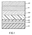
本発明による典型的な構造を図1に示してある。これは小分子デバイスにおいて特に有用である。この構造は、基板101と、アノード103と、正孔注入層105と、正孔輸送層107と、発光層109と、電子輸送層111と、カソード113を備えている。これらの層について以下に詳細に説明する。基板101をカソード113に隣接した位置にすることや、基板101が実際にアノード103またはカソード113を構成することも可能であることに注意されたい。アノード103とカソード113に挟まれた有機層を、便宜上、有機EL素子と呼ぶ。また、有機層を合計した厚さは、500nm未満であることが望ましい。このデバイスがリン光材料を含んでいる場合には、発光層と電子輸送層の間に正孔阻止層が存在していてもよい。
A typical structure according to the present invention is shown in FIG. This is particularly useful in small molecule devices. This structure includes a
OLEDのアノード103とカソード113は、導電体を通じて電圧/電流源に接続されている。OLEDは、アノード103とカソード113の間に、アノード103がカソード113と比べて正の電位となるように電圧を印加することによって動作する。正孔はアノード103から有機EL素子に注入され、電子はカソード113から有機EL素子に注入される。ACモードではACサイクル中にポテンシャル・バイアスが逆転して電流が流れないわずかな期間があるため、OLEDをACモードで動作させるときにデバイスの安定性向上を実現できることがときにある。AC駆動のOLEDの一例が、アメリカ合衆国特許第5,552,678号に記載されている。
The
基板 substrate
本発明のOLEDデバイスは支持用基板101の上に形成されて、カソード113またはアノード103が基板と接触できるようになっているのが一般的である。基板101と接触する電極は、通常、底部電極と呼ばれる。底部電極はアノード103であることが一般的であるが、本発明がこの構成に限定されることはない。基板101は、どの方向に光を出したいかに応じ、透過性または不透明にすることができる。透光特性は、基板101を通してEL光を見る上で望ましい。その場合には、透明なガラスまたはプラスチックが一般に用いられる。基板101は、多数の材料層を含む複合構造にすることができる。これは、一般に、TFTがOLED層の下に設けられるアクティブ・マトリックス基板の場合である。しかし基板101は、少なくとも光を出す画素化領域において、大部分が透明な材料(例えばガラスまたはポリマー)でできている必要がある。EL光を上部電極を通じて見るような用途では、底部支持体の透過特性は重要でないため、底部支持体は、光透過性、光吸収性、光反射性のいずれでもよい。この場合に用いる基板としては、ガラス、プラスチック、半導体材料(例えばシリコン)、セラミック、回路板材料などがある。この場合にも、基板101は、アクティブ・マトリックスTFTの設計に見られるように、多数の材料層を含む複合構造にすることができる。このような構成のデバイスでは、透光性のある上部電極を設ける必要がある。
The OLED device of the present invention is generally formed on a supporting
アノード anode
エレクトロルミネッセンス光(EL)をアノードを通して見る場合には、アノード103は、興味の対象となる光に対して透明か、実質的に透明である必要がある。本発明で用いられる透明なアノード用の一般的な材料は、インジウム-スズ酸化物(ITO)、インジウム-亜鉛酸化物(IZO)、スズ酸化物であるが、他の金属酸化物(例えばアルミニウムをドープした亜鉛酸化物、インジウムをドープした亜鉛酸化物、マグネシウム-インジウム酸化物、ニッケル-タングステン酸化物)も可能である。これら酸化物に加え、金属窒化物(例えば窒化ガリウム)、金属セレン化物(例えばセレン化亜鉛)、金属硫化物(例えば硫化亜鉛)をアノード103として用いることができる。EL光をカソード113だけを通して見るような用途では、アノード103の透過特性は重要でなく、あらゆる導電性材料(透明なもの、不透明なもの、反射性のもの)を使用することができる。この用途での具体的な導電性材料としては、金、イリジウム、モリブデン、パラジウム、白金などがある。典型的なアノード用材料は、透光性であろうとそうでなかろうと、仕事関数が4.1eV以上である。望ましいアノード用材料は、一般に適切な任意の手段(例えば蒸着、スパッタリング、化学蒸着、電気化学的手段)で堆積させる。アノードは、よく知られているフォトリソグラフィ法を利用してパターニングすることができる。場合によっては、アノードを研磨した後に他の層を付着させて表面の粗さを小さくすることで、短絡を最少にすること、または反射性を大きくすることができる。
When viewing electroluminescent light (EL) through the anode, the
カソード Cathode
アノード103だけを通して光を見る場合には、本発明で使用するカソード113は、ほぼ任意の導電性材料で構成することができる。望ましい材料は優れた膜形成特性を有するため、下にある有機層との接触がよくなり、低電圧で電子の注入が促進され、優れた安定性を得ることができる。有用なカソード材料は、仕事関数が小さな(4.0eV未満)金属または合金を含んでいることがしばしばある。有用な1つのカソード材料は、アメリカ合衆国特許第4,885,221号に記載されているように、銀が1〜20%の割合で含まれたMg:Ag合金からなる。適切なカソード材料の別のクラスとして、カソードと、有機層(例えば電子輸送層(ETL))に接する薄い電子注入層(EIL)とを備えていて、カソードの上により厚い導電性金属層を被せた構成の二層がある。その場合、EILは、仕事関数が小さな金属または金属塩を含んでいることが好ましく、そうなっている場合には、より厚い被覆層は仕事関数が小さい必要がない。このような1つのカソードは、アメリカ合衆国特許第5,677,572号に記載されているように、LiFからなる薄い層と、その上に載るより厚いAl層からなる。アルカリ金属をドープしたETL材料(例えばLiをドープしたAlq)は、有用なEILの別の一例である。他の有用なカソード材料としては、アメリカ合衆国特許第5,059,961号、第5,059,862号、第6,140,763号に開示されているものがあるが、これだけに限定されるわけではない。
When viewing light only through the
カソードを通して発光を見る場合、カソード113は、透明であるか、ほぼ透明である必要がある。このような用途のためには、金属が薄いか、透明な導電性酸化物を使用するか、このような材料の組み合わせを使用する必要がある。光学的に透明なカソードは、アメリカ合衆国特許第4,885,211号、第5,247,190号、日本国特許第3,234,963号、アメリカ合衆国特許第5,703,436号、第5,608,287号、第5,837,391号、第5,677,572号、第5,776,622号、第5,776,623号、第5,714,838号、第5,969,474号、第5,739,545号、第5,981,306号、第6,137,223号、第6,140,763号、第6,172,459号、ヨーロッパ特許第1,076,368号、アメリカ合衆国特許第6,278,236号、第6,284,393号に、より詳細に記載されている。カソード材料は、一般に、適切な任意の方法(例えば蒸着、スパッタリング、化学蒸着)によって堆積させる。必要な場合には、よく知られた多数の方法でパターニングすることができる。方法としては、例えば、スルー・マスク蒸着、アメリカ合衆国特許第5,276,380号とヨーロッパ特許第0,732,868号に記載されている一体化シャドウ・マスキング、レーザー除去、選択的化学蒸着などがある。
When viewing light emission through the cathode, the
正孔注入層(HIL) Hole injection layer (HIL)
正孔注入層105をアノード103と正孔輸送層107の間に設けることができる。正孔注入層は、後に続く有機層のフィルム形成能力を向上させ、正孔を正孔輸送層107に容易に注入できるようにする機能を持つことができる。正孔注入層105で使用するのに適した材料としては、アメリカ合衆国特許第4,720,432号に記載されているポルフィリン化合物や、アメリカ合衆国特許第6,208,075号に記載されているプラズマ堆積させたフルオロカーボン・ポリマーや、いくつかの芳香族アミン(例えばMTDATA(4,4',4"-トリス[(3-メチルフェニル)フェニルアミノ]トリフェニルアミン))などがある。有機ELデバイスにおいて有用であることが報告されている別の正孔注入材料は、ヨーロッパ特許第0,891,121 A1号と第1,029,909 A1号に記載されている。正孔注入層を本発明で用いることが好ましく、それはプラズマ堆積させたフルオロカーボン・ポリマーであることが望ましい。プラズマ堆積させたフルオロカーボン・ポリマーを含む正孔注入層の厚さは、0.2nm〜15nmの範囲が可能であり、0.3〜1.5nmの範囲であることが好ましい。
A
正孔輸送層(HTL) Hole transport layer (HTL)
必ずしも必要なわけではないが、OLEDデバイスに正孔輸送層を含めると有用であることがしばしばある。有機ELデバイスの正孔輸送層107は、少なくとも1つの正孔輸送化合物(例えば芳香族第三級アミン)を含んでいる。芳香族第三級アミンは、炭素原子(そのうちの少なくとも1つは芳香族環のメンバーである)だけに結合する少なくとも1つの3価窒素原子を含んでいる化合物であると理解されている。芳香族第三級アミンの1つの形態は、アリールアミン(例えばモノアリールアミン、ジアリールアミン、トリアリールアミン、ポリマー・アリールアミン)である。具体的なモノマー・トリアリールアミンは、Klupfelらによってアメリカ合衆国特許第3,180,730号に示されている。1個以上のビニル基で置換された他の適切なトリアリールアミン、および/または少なくとも1つの活性な水素含有基を含む他の適切なトリアリールアミンは、Brantley他によってアメリカ合衆国特許第3,567,450号と第3,658,520号に開示されている。
Although not necessary, it is often useful to include a hole transport layer in an OLED device. The
芳香族第三級アミンのより好ましいクラスは、アメリカ合衆国特許第4,720,432号と第5,061,569号に記載されているように、少なくとも2つの芳香族第三級アミン部分を含むものである。このような化合物としては、構造式(A):
構造式(A)に合致するとともに2つのトリアリールアミンを含むトリアリールアミンの有用な1つのクラスは、構造式(B):
R1とR2は、それぞれ独立に、水素原子、アリール基、アルキル基のいずれかを表わすか、R1とR2は、合わさって、シクロアルキル基を完成させる原子を表わし;
R3とR4は、それぞれ独立にアリール基を表わし、そのアリール基は、構造式(C):
R5とR6は、独立に、アリール基の中から選択される。一実施態様では、R5とR6のうちの少なくとも一方は、多環縮合環構造(例えばナフタレン)を含んでいる。
One useful class of triarylamines that conform to structural formula (A) and contain two triarylamines is structural formula (B):
R 1 and R 2 each independently represent a hydrogen atom, an aryl group, or an alkyl group, or R 1 and R 2 together represent an atom that completes a cycloalkyl group;
R 3 and R 4 each independently represents an aryl group, and the aryl group has the structural formula (C):
R 5 and R 6 are independently selected from aryl groups. In one embodiment, at least one of R 5 and R 6 includes a polycyclic fused ring structure (eg, naphthalene).
芳香族第三級アミンの別のクラスは、テトラアリールジアミンである。望ましいテトラアリールジアミンとして、構造式(C)に示したように、アリーレン基を通じて結合した2つのジアリールアミノ基が挙げられる。有用なテトラアリールジアミンとしては、一般式(D):
それぞれのAreは、独立に、アリーレン基(例えばフェニレン基またはアントラセン基)の中から選択され;
nは1〜4の整数であり;
Ar、R7、R8、R9は、独立に、アリール基の中から選択される。
Another class of aromatic tertiary amines are tetraaryldiamines. Desirable tetraaryldiamines include two diarylamino groups bonded through an arylene group as shown in Structural Formula (C). Useful tetraaryldiamines include general formula (D):
Each Are independently selected from an arylene group (eg, a phenylene group or an anthracene group);
n is an integer from 1 to 4;
Ar, R 7 , R 8 and R 9 are independently selected from aryl groups.
典型的な一実施態様では、Ar、R7、R8、R9のうちの少なくとも1つは多環縮合構造(例えばナフタレン)である。 In one exemplary embodiment, at least one of Ar, R 7 , R 8 , R 9 is a polycyclic fused structure (eg, naphthalene).
上記の構造式(A)、(B)、(C)、(D)のさまざまなアルキル部分、アルキレン部分、アリール部分、アリーレン部分は、それぞれ、置換されていてもよい。典型的な置換基としては、アルキル基、アルコキシ基、アリール基、アリールオキシ基、ハロゲン(例えばフッ化物、塩化物、臭化物)などがある。さまざまなアルキル部分とアルキレン部分は、一般に、1〜約6個の炭素原子を含んでいる。シクロアルキル部分は、3〜約10個の炭素原子を含むことができるが、一般には5個、または6個、または7個の炭素原子を含んでいる(例えばシクロペンチル環構造、シクロヘキシル環構造、シクロヘプチル環構造)。アリール基とアリーレン基は、通常は、フェニル部分とフェニレン部分である。 The various alkyl, alkylene, aryl, and arylene moieties in the above structural formulas (A), (B), (C), and (D) may each be substituted. Typical substituents include alkyl groups, alkoxy groups, aryl groups, aryloxy groups, halogens (eg, fluoride, chloride, bromide) and the like. The various alkyl and alkylene moieties generally contain from 1 to about 6 carbon atoms. Cycloalkyl moieties can contain from 3 to about 10 carbon atoms, but generally contain 5 or 6 or 7 carbon atoms (eg, cyclopentyl ring structure, cyclohexyl ring structure, cyclohexane, Heptyl ring structure). Aryl and arylene groups are usually phenyl and phenylene moieties.
正孔輸送層は、単一の芳香族第三級アミン化合物で、または芳香族第三級アミン化合物の混合物で形成することができる。特に、トリアリールアミン(例えば構造式(B)を満たすトリアリールアミン)をテトラアリールジアミン(例えば構造式(D)に示したもの)と組み合わせて使用することができる。有用な芳香族第三級アミンの具体例としては、以下のものがある。
1,1-ビス(4-ジ-p-トリルアミノフェニル)シクロヘキサン(TAPC)
1,1-ビス(4-ジ-p-トリルアミノフェニル)-4-メチルシクロヘキサン
1,1-ビス(4-ジ-p-トリルアミノフェニル)-4-フェニルシクロヘキサン
1,1-ビス(4-ジ-p-トリルアミノフェニル)-3-フェニルプロパン(TAPPP)
N,N,N',N'-テトラフェニル-4,4"'-ジアミノ-1,1':4',1":4",1"'-クアテルフェニル
ビス(4-ジメチルアミノ-2-メチルフェニル)フェニルメタン
1,4-ビス[2-[4-[N,N-ジ(p-トリル)アミノ]フェニル]ビニル]ベンゼン(BDTAPVB)
N,N,N',N'-テトラ-p-トリル-4,4'-ジアミノビフェニル(TTB)
N,N,N',N'-テトラフェニル-4,4'-ジアミノビフェニル
N,N,N',N'-テトラ-1-ナフチル-4,4'-ジアミノビフェニル
N,N,N',N'-テトラ-2-ナフチル-4,4'-ジアミノビフェニル
N-フェニルカルバゾール
4,4'-ビス[N-(1-ナフチル)-N-フェニルアミノ]ビフェニル(NPB)
4,4'-ビス[N-(1-ナフチル)-N-(2-ナフチル)アミノ]ビフェニル(TNB)
4,4'-ビス[N-(1-ナフチル)-N-フェニルアミノ]p-テルフェニル
4,4'-ビス[N-(2-ナフチル)-N-フェニルアミノ]ビフェニル
4,4'-ビス[N-(3-アセナフテニル)-N-フェニルアミノ]ビフェニル
1,5-ビス[N-(1-ナフチル)-N-フェニルアミノ]ナフタレン
4,4'-ビス[N-(9-アントリル)-N-フェニルアミノ]ビフェニル
4,4'-ビス[N-(1-アントリル)-N-フェニルアミノ]-p-テルフェニル
4,4'-ビス[N-(2-フェナントリル)-N-フェニルアミノ]ビフェニル
4,4'-ビス[N-(8-フルオランテニル)-N-フェニルアミノ]ビフェニル
4,4'-ビス[N-(2-ピレニル)-N-フェニルアミノ]ビフェニル
4,4'-ビス[N-(2-ナフタセニル)-N-フェニルアミノ]ビフェニル
4,4'-ビス[N-(2-ペリレニル)-N-フェニルアミノ]ビフェニル
4,4'-ビス[N-(1-コロネニル)-N-フェニルアミノ]ビフェニル
2,6-ビス(ジ-p-トリルアミノ)ナフタレン
2,6-ビス[ジ-(1-ナフチル)アミノ]ナフタレン
2,6-ビス[N-(1-ナフチル)-N-(2-ナフチル)アミノ]ナフタレン
N,N,N',N'-テトラ(2-ナフチル)-4,4"-ジアミノ-p-テルフェニル
4,4'-ビス{N-フェニル-N-[4-(1-ナフチル)-フェニル]アミノ}ビフェニル
2,6-ビス[N,N-ジ(2-ナフチル)アミン]フルオレン
4,4',4"-トリス[(3-メチルフェニル)フェニルアミノ]トリフェニルアミン(MTDATA)
4,4'-ビス[N-(3-メチルフェニル)-N-フェニルアミノ]ビフェニル(TPD)。
The hole transport layer can be formed of a single aromatic tertiary amine compound or a mixture of aromatic tertiary amine compounds. In particular, a triarylamine (for example, a triarylamine satisfying the structural formula (B)) can be used in combination with a tetraaryldiamine (for example, one represented by the structural formula (D)). Specific examples of useful aromatic tertiary amines include the following.
1,1-bis (4-di-p-tolylaminophenyl) cyclohexane (TAPC)
1,1-bis (4-di-p-tolylaminophenyl) -4-methylcyclohexane
1,1-bis (4-di-p-tolylaminophenyl) -4-phenylcyclohexane
1,1-bis (4-di-p-tolylaminophenyl) -3-phenylpropane (TAPPP)
N, N, N ', N'-Tetraphenyl-4,4 "'-diamino-1,1 ': 4', 1": 4 ", 1"'-quaterphenyl bis (4-dimethylamino-2 -Methylphenyl) phenylmethane
1,4-Bis [2- [4- [N, N-di (p-tolyl) amino] phenyl] vinyl] benzene (BDTAPVB)
N, N, N ', N'-Tetra-p-tolyl-4,4'-diaminobiphenyl (TTB)
N, N, N ', N'-Tetraphenyl-4,4'-diaminobiphenyl
N, N, N ', N'-tetra-1-naphthyl-4,4'-diaminobiphenyl
N, N, N ', N'-tetra-2-naphthyl-4,4'-diaminobiphenyl
N-phenylcarbazole
4,4'-bis [N- (1-naphthyl) -N-phenylamino] biphenyl (NPB)
4,4'-bis [N- (1-naphthyl) -N- (2-naphthyl) amino] biphenyl (TNB)
4,4'-bis [N- (1-naphthyl) -N-phenylamino] p-terphenyl
4,4'-bis [N- (2-naphthyl) -N-phenylamino] biphenyl
4,4'-bis [N- (3-acenaphthenyl) -N-phenylamino] biphenyl
1,5-bis [N- (1-naphthyl) -N-phenylamino] naphthalene
4,4'-bis [N- (9-anthryl) -N-phenylamino] biphenyl
4,4'-bis [N- (1-anthryl) -N-phenylamino] -p-terphenyl
4,4'-bis [N- (2-phenanthryl) -N-phenylamino] biphenyl
4,4'-bis [N- (8-fluoranthenyl) -N-phenylamino] biphenyl
4,4'-bis [N- (2-pyrenyl) -N-phenylamino] biphenyl
4,4'-bis [N- (2-naphthacenyl) -N-phenylamino] biphenyl
4,4'-bis [N- (2-perylenyl) -N-phenylamino] biphenyl
4,4'-bis [N- (1-coronenyl) -N-phenylamino] biphenyl
2,6-bis (di-p-tolylamino) naphthalene
2,6-Bis [di- (1-naphthyl) amino] naphthalene
2,6-Bis [N- (1-naphthyl) -N- (2-naphthyl) amino] naphthalene
N, N, N ', N'-tetra (2-naphthyl) -4,4 "-diamino-p-terphenyl
4,4'-bis {N-phenyl-N- [4- (1-naphthyl) -phenyl] amino} biphenyl
2,6-Bis [N, N-di (2-naphthyl) amine] fluorene
4,4 ', 4 "-Tris [(3-methylphenyl) phenylamino] triphenylamine (MTDATA)
4,4'-bis [N- (3-methylphenyl) -N-phenylamino] biphenyl (TPD).
有用な正孔輸送材料の別のクラスとして、ヨーロッパ特許1,009,041に記載されている多環式芳香族化合物がある。3つ以上のアミン基を有する第三級芳香族アミン(例えばオリゴマー材料)を使用できる。さらに、ポリマー正孔輸送材料を使用することができる。それは、例えば、ポリ(N-ビニルカルバゾール)(PVK)、ポリチオフェン、ポリピロール、ポリアニリン、コポリマー(例えばポリ(3,4-エチレンジオキシチオフェン)/ポリ(4-スチレンスルホネート)(PEDOT/PSSとも呼ばれる))などである。正孔輸送層は、組成が異なる2つ以上の下位層を含むことも可能である。なおそれぞれの下位層の組成は、上に説明した通りである。正孔輸送層の厚さは、10〜約500nmにすることができ、50〜300nmが好ましい。 Another class of useful hole transport materials is the polycyclic aromatic compounds described in European Patent 1,009,041. Tertiary aromatic amines (eg oligomeric materials) having more than two amine groups can be used. In addition, polymeric hole transport materials can be used. For example, poly (N-vinylcarbazole) (PVK), polythiophene, polypyrrole, polyaniline, copolymer (eg poly (3,4-ethylenedioxythiophene) / poly (4-styrenesulfonate) (also called PEDOT / PSS) ) Etc. The hole transport layer may include two or more lower layers having different compositions. The composition of each lower layer is as described above. The thickness of the hole transport layer can be 10 to about 500 nm, with 50 to 300 nm being preferred.
発光層(LEL) Light emitting layer (LEL)
ELデバイスにおいて有用な発光材料には蛍光材料が含まれる。アメリカ合衆国特許第4,769,292号、第5,935,721号により詳しく説明されているように、有機EL素子の発光層(LEL)は発光材料を含んでおり、この領域で電子-正孔対の再結合が起こる結果としてエレクトロルミネッセンスが生じる。発光層は単一の材料で構成できるが、より一般的には、1つまたは複数のゲスト化合物をドープしたホスト材料からなる。光は主として発光材料から発生し、任意の色が可能である。 Luminescent materials useful in EL devices include fluorescent materials. As described in more detail in US Pat. Nos. 4,769,292 and 5,935,721, the light emitting layer (LEL) of an organic EL device contains a light emitting material, and as a result of electron-hole pair recombination in this region. Electroluminescence occurs. The light emitting layer can be composed of a single material, but more generally consists of a host material doped with one or more guest compounds. Light mainly originates from the luminescent material and can be any color.
本発明のホスト材料は、別のホスト材料と組み合わせて使用することができ、その材料は同じ層の中にあってもよいし、別の層の中にあってもよい。発光層内のホスト材料は、以下に示す電子輸送材料、または上記の正孔輸送材料、または正孔-電子再結合をサポートする別の単一の材料または組み合わせた材料にすることができる。蛍光発光材料は、一般に、0.01〜10質量%の割合でホスト材料に組み込まれる。 The host material of the present invention can be used in combination with another host material, which may be in the same layer or in another layer. The host material in the light emitting layer can be the electron transport material shown below, or the hole transport material described above, or another single material or combination material that supports hole-electron recombination. The fluorescent material is generally incorporated into the host material at a rate of 0.01 to 10% by weight.
ホスト材料および発光材料としては、小さな非ポリマー分子またはポリマー材料が可能である(例えばポリフルオレン、ポリビニルアリーレン(例えばポリ(p-フェニレンビニレン)、PPV))。ポリマーの場合、小分子発光材料は、ホスト・ポリマーの中に分子として分散させること、または発光材料を微量成分とコポリマー化してホスト・ポリマーに添加することができる。膜形成、電気特性、発光効率、動作寿命、製造しやすさを改善するため、ホスト材料を互いに混合することができる。ホストは、優れた正孔輸送特性を有する材料と、優れた電子輸送特性を有する材料を含むことができる。 The host material and luminescent material can be small non-polymeric molecules or polymeric materials (eg, polyfluorene, polyvinylarylene (eg, poly (p-phenylene vinylene), PPV)). In the case of a polymer, the small molecule light emitting material can be dispersed as a molecule in the host polymer, or the light emitting material can be copolymerized with a minor component and added to the host polymer. Host materials can be mixed together to improve film formation, electrical properties, luminous efficiency, operating life, and ease of manufacture. The host can include a material having excellent hole transport properties and a material having excellent electron transport properties.
ゲスト発光材料として蛍光材料を選択する際の重要な1つの関係は、ホスト材料と蛍光材料の励起一重項状態のエネルギーの比較である。蛍光材料の励起一重項状態のエネルギーは、ホスト材料の励起一重項状態のエネルギーよりも低いことが非常に望ましい。励起一重項状態のエネルギーは、発光する一重項状態と基底状態のエネルギー差として定義される。非発光性ホストに関しては、基底状態と同じ電子スピンの最低励起状態が発光状態であると考えられる。 One important relationship in selecting a fluorescent material as the guest luminescent material is a comparison of the excited singlet state energies of the host material and the fluorescent material. It is highly desirable that the excited singlet state energy of the fluorescent material be lower than the excited singlet state energy of the host material. The energy of the excited singlet state is defined as the energy difference between the emitting singlet state and the ground state. For non-luminescent hosts, the lowest excited state of the same electron spin as the ground state is considered to be the luminescent state.
有用であることが知られているホスト材料および発光材料としては、アメリカ合衆国特許第4,768,292号、第5,141,671号、第5,150,006号、第5,151,629号、第5,405,709号、第5,484,922号、第5,593,788号、第5,645,948号、第5,683,823号、第5,755,999号、第5,928,802号、第5,935,720号、第5,935,721号、第6,020,078号に開示されているものなどがある。 Host and luminescent materials known to be useful include U.S. Pat.Nos. 4,768,292, 5,141,671, 5,150,006, 5,151,629, 5,405,709, 5,484,922, 5,593,788, and 5,645,948. No. 5,683,823, No. 5,755,999, No. 5,928,802, No. 5,935,720, No. 5,935,721, No. 6,020,078, and the like.
8-ヒドロキシキノリンの金属錯体と、それと同様の誘導体(金属キレート化オキシノイド化合物としても知られる)(一般式E)は、エレクトロルミネッセンスをサポートすることのできる有用なホスト材料の1つのクラスを形成し、波長が500nmよりも長い光(例えば緑、黄、オレンジ、赤)を出させるのに特に適している。 Metal complexes of 8-hydroxyquinoline and similar derivatives (also known as metal chelated oxinoid compounds) (general formula E) form one class of useful host materials that can support electroluminescence. Particularly suitable for emitting light having a wavelength longer than 500 nm (for example, green, yellow, orange, red).
nは1〜4の整数であり;
Zは、各々に独立に、縮合した少なくとも2つの芳香族環を有する核を完成させる原子を表わす。
n is an integer from 1 to 4;
Z each independently represents an atom that completes a nucleus having at least two fused aromatic rings.
以上の説明から、金属は、一価、二価、三価、四価の金属が可能であることが明らかである。金属としては、例えばアルカリ金属(リチウム、ナトリウム、カリウムなど)、アルカリ土類金属(マグネシウム、カルシウムなど)、三価の金属(アルミニウム、ガリウムなど);他の金属(亜鉛、ジルコニウムなど)が可能である。一般に、キレート化金属として有用であることが知られている任意の一価、二価、三価、四価の金属を使用することができる。 From the above description, it is clear that the metal can be a monovalent, divalent, trivalent, or tetravalent metal. Examples of metals include alkali metals (lithium, sodium, potassium, etc.), alkaline earth metals (magnesium, calcium, etc.), trivalent metals (aluminum, gallium, etc.); other metals (zinc, zirconium, etc.). is there. In general, any monovalent, divalent, trivalent, or tetravalent metal known to be useful as a chelating metal can be used.
Zは、縮合した少なくとも2つの芳香族環を持っていてそのうちの少なくとも一方はアゾール環またはアジン環である複素環の核を完成させる。必要な場合には、必要なその2つの環に追加の環(例えば脂肪族環と芳香族環の両方)を縮合させることができる。機能の向上なしに分子が大きくなることを避けるため、環の原子数は、通常は18個以下に維持する。 Z completes a heterocyclic nucleus having at least two fused aromatic rings, at least one of which is an azole or azine ring. If necessary, additional rings (such as both aliphatic and aromatic rings) can be fused to the two required rings. The number of ring atoms is usually kept at 18 or less in order to avoid molecular growth without improving function.
有用なキレート化オキシノイド系化合物の具体例としては、以下のものがある。
CO-1:アルミニウムトリスオキシン[別名、トリス(8-キノリノラト)アルミニウム(III)]
CO-2:マグネシウムビスオキシン[別名、ビス(8-キノリノラト)マグネシウム(II)]
CO-3:ビス[ベンゾ{f}-8-キノリノラト]亜鉛(II)
CO-4:ビス(2-メチル-8-キノリノラト)アルミニウム(III)-μ-オキソ-ビス(2-メチル-8-キノリノラト)アルミニウム(III)
CO-5:インジウムトリスオキシン[別名、トリス(8-キノリノラト)インジウム]
CO-6:アルミニウムトリス(5-メチルオキシン)[別名、トリス(5-メチル-8-キノリノラト)アルミニウム(III)]
CO-7:リチウムオキシン[別名、(8-キノリノラト)リチウム(I)]
CO-8:ガリウムオキシン[別名、トリス(8-キノリノラト)ガリウム(III)]
CO-9:ジルコニウムオキシン[別名、テトラ(8-キノリノラト)ジルコニウム(IV)]
Specific examples of useful chelated oxinoid compounds include the following.
CO-1: Aluminum trisoxin [also known as tris (8-quinolinolato) aluminum (III)]
CO-2: Magnesium bisoxin [Also known as bis (8-quinolinolato) magnesium (II)]
CO-3: Bis [benzo {f} -8-quinolinolato] zinc (II)
CO-4: Bis (2-methyl-8-quinolinolato) aluminum (III) -μ-oxo-bis (2-methyl-8-quinolinolato) aluminum (III)
CO-5: Indium trisoxin [aka tris (8-quinolinolato) indium]
CO-6: Aluminum tris (5-methyloxin) [aka tris (5-methyl-8-quinolinolato) aluminum (III)]
CO-7: Lithium oxine [aka, (8-quinolinolato) lithium (I)]
CO-8: Gallium Oxin [Also known as Tris (8-quinolinolato) gallium (III)]
CO-9: Zirconium Oxin [Also known as Tetra (8-quinolinolato) zirconium (IV)]
9,10-ジ-(2-ナフチル)アントラセンの誘導体(一般式F)は、エレクトロルミネッセンスをサポートすることのできる有用なホスト材料の1つのクラスを形成し、波長が400nmよりも長い光(例えば青、緑、黄、オレンジ、赤)を出させるのに特に適している。 Derivatives of 9,10-di- (2-naphthyl) anthracene (general formula F) form one class of useful host materials that can support electroluminescence, with wavelengths longer than 400 nm (eg Blue, green, yellow, orange, red) is particularly suitable.
R1、R2、R3、R4、R5、R6は、各環上にある、以下に示すグループの中から選択した1個以上の置換基を表わす。
グループ1:水素、または1〜24個の炭素原子を有するアルキル;
グループ2:5〜20個の炭素原子を有するアリールまたは置換されたアリール;
グループ3:アントラセニル、ピレニル、ペリレニルいずれかの芳香族縮合環を完成させるのに必要な4〜24個の炭素原子;
グループ4:フリル、チエニル、ピリジル、キノリニル、または他の複素環系の複素芳香族縮合環を完成させるのに必要な、5〜24個の炭素原子を有するヘテロアリールまたは置換されたヘテロアリール;
グループ5:1〜24個の炭素原子を有するアルコキシアミノ、アルキルアミノ、アリールアミノ;
グループ6:フッ素、塩素、ホウ素、シアノ。
R 1 , R 2 , R 3 , R 4 , R 5 and R 6 represent one or more substituents selected from the following groups on each ring.
Group 1: hydrogen or alkyl having 1 to 24 carbon atoms;
Group 2: aryl having 5 to 20 carbon atoms or substituted aryl;
Group 3: 4 to 24 carbon atoms necessary to complete an anthracenyl, pyrenyl, or perylenyl aromatic fused ring;
Group 4: heteroaryl having 5 to 24 carbon atoms or substituted heteroaryl necessary to complete a heteroaromatic fused ring of furyl, thienyl, pyridyl, quinolinyl, or other heterocyclic ring systems;
Group 5: alkoxyamino, alkylamino, arylamino having 1 to 24 carbon atoms;
Group 6: Fluorine, chlorine, boron, cyano.
代表的な具体例として、9,10-ジ-(2-ナフチル)アントラセンと2-t-ブチル-9,10-ジ-(2-ナフチル)アントラセンがある。他のアントラセン誘導体もLELにおけるホストとして役に立つ可能性があり、例えば9,10-ビス[4-(2,2-ジフェニルエテニル)フェニル]アントラセンの誘導体がある。 Typical examples are 9,10-di- (2-naphthyl) anthracene and 2-t-butyl-9,10-di- (2-naphthyl) anthracene. Other anthracene derivatives may also serve as hosts in LEL, for example, derivatives of 9,10-bis [4- (2,2-diphenylethenyl) phenyl] anthracene.
ベンズアゾール誘導体(一般式G)は、エレクトロルミネッセンスをサポートすることのできる有用なホスト材料の1つのクラスを形成し、波長が400nmよりも長い光(例えば青、緑、黄、オレンジ、赤)を出させるのに特に適している。 Benzazole derivatives (general formula G) form one class of useful host materials that can support electroluminescence and emit light with wavelengths longer than 400 nm (eg blue, green, yellow, orange, red) Especially suitable for getting out.
Zは、O、NR、Sのいずれかであり;
RとR'は、独立に、水素;1〜24個の炭素原子を有するアルキル(例えばプロピル、t-ブチル、ヘプチルなど);5〜20個の炭素原子を有するアリールまたはヘテロ原子で置換されたアリール(例えばフェニル、ナフチル、フリル、チエニル、ピリジル、キノリニル、ならびに他の複素環式系);ハロ(例えばクロロ、フルオロ);芳香族縮合環を完成させるのに必要な原子のいずれかであり;
Lは、アルキル、アリール、置換されたアルキル、置換されたアリールのいずれかを含んでいる結合単位であり、複数のベンズアゾールを互いに共役または非共役に結合させる。Lは、複数のベンズアゾールと共役していてもいなくてもよい。有用なベンズアゾールの一例は、2,2',2"-(1,3,5-フェニレン)トリス[1-フェニル-1H-ベンゾイミダゾール]である。
Z is either O, NR or S;
R and R ′ are independently substituted with hydrogen; alkyl having 1 to 24 carbon atoms (eg, propyl, t-butyl, heptyl, etc.); aryl or heteroatom having 5 to 20 carbon atoms Aryl (eg, phenyl, naphthyl, furyl, thienyl, pyridyl, quinolinyl, and other heterocyclic systems); halo (eg, chloro, fluoro); any of the atoms necessary to complete an aromatic fused ring;
L is a binding unit containing any of alkyl, aryl, substituted alkyl, and substituted aryl, and binds a plurality of benzazoles to each other in a conjugated or non-conjugated manner. L may or may not be conjugated to a plurality of benzazoles. An example of a useful benzazole is 2,2 ', 2 "-(1,3,5-phenylene) tris [1-phenyl-1H-benzimidazole].
アメリカ合衆国特許第5,121,029号と日本国特開08-333569に記載されているスチリルアリーレン誘導体も、青色を発光させるための有用なホスト材料である。例えば9,10-ビス[4-(2,2-ジフェニルエテニル)フェニル]アントラセンと4,4'-ビス(2,2-ジフェニルエテニル)-1,1'-ビフェニル(DPVBi)は、青色を発光させるための有用なホスト材料である。 The styrylarylene derivatives described in US Pat. No. 5,121,029 and Japanese Patent Application Laid-Open No. 08-333569 are also useful host materials for emitting blue light. For example, 9,10-bis [4- (2,2-diphenylethenyl) phenyl] anthracene and 4,4'-bis (2,2-diphenylethenyl) -1,1'-biphenyl (DPVBi) are blue Is a useful host material for emitting light.
有用な蛍光発光材料としては、アントラセン、テトラセン、キサンテン、ペリレン、ルブレン、クマリン、ローダミン、キナクリドンの誘導体や、ジシアノメチレンピラン化合物、チオピラン化合物、ポリメチン化合物、ピリリウム化合物、チアピリリウム化合物、フルオレン誘導体、ペリフランテン誘導体、インデノペリレン誘導体、ビス(アジニル)アミンホウ素化合物、ビス(アジニル)メタン化合物、カルボスチリル化合物などがある。有用な材料の代表例としては、以下のものがある。 Useful fluorescent materials include anthracene, tetracene, xanthene, perylene, rubrene, coumarin, rhodamine, quinacridone derivatives, dicyanomethylene pyran compounds, thiopyran compounds, polymethine compounds, pyrylium compounds, thiapyrylium compounds, fluorene derivatives, perifanthene derivatives, Indenoperylene derivatives, bis (azinyl) amine boron compounds, bis (azinyl) methane compounds, carbostyryl compounds, and the like. Representative examples of useful materials include:
蛍光発光材料に加え、リン光発光材料もELデバイスで用いることができる。便宜上、リン光錯体ゲスト材料を、この明細書ではリン光材料と呼ぶ。リン光材料は、一般に、1つ以上のリガンド(例えばsp2炭素とヘテロ原子を通じて金属と配位することができるモノアニオン・リガンド)を含んでいる。リガンドは、フェニルピリジン(ppy)、またはその誘導体、またはそのアナログにすることができる。有用なリン光有機金属材料のいくつかの具体例として、トリス(2-フェニルピリジナト-N,C2')イリジウム(III)、ビス(2-フェニルピリジナト-N,C2)イリジウム(III)(アセチルアセトネート)、ビス(2-フェニルピリジナト-N,C2')白金(II)などがある。好ましいことに、多数のリン光有機金属材料がスペクトルの緑色領域で発光する。すなわち510〜570nmの範囲で発光が最大になる。 In addition to fluorescent materials, phosphorescent materials can also be used in EL devices. For convenience, the phosphorescent complex guest material is referred to herein as a phosphorescent material. The phosphorescent material generally includes one or more ligands (eg, a monoanionic ligand that can coordinate with the metal through the sp 2 carbon and heteroatom). The ligand can be phenylpyridine (ppy), or a derivative thereof, or an analog thereof. Some specific examples of useful phosphorescent organometallic materials include tris (2-phenylpyridinato-N, C 2 ′ ) iridium (III), bis (2-phenylpyridinato-N, C 2 ) iridium (III) (acetylacetonate), bis (2-phenylpyridinato-N, C 2 ′ ) platinum (II), and the like. Preferably, many phosphorescent organometallic materials emit in the green region of the spectrum. That is, light emission is maximized in the range of 510 to 570 nm.
リン光材料は、単独で、または他のリン光材料と組み合わせて、同じ層または異なる層て使用することができる。リン光材料と適切なホストが記載されているのは、WO 00/57676、WO 00/70655、WO 01/41512 A1、WO 02/15645 A1、アメリカ合衆国特許出願2003/0017361 A1、WO 01/93642 A1、WO 01/39234 A2、アメリカ合衆国特許第6,458,475 B1号、WO 02/071813 A1、アメリカ合衆国特許第6,573,651 B2号、アメリカ合衆国特許出願2002/0197511 A1、WO 02/074015 A2、アメリカ合衆国特許第6,451,455 B1号、アメリカ合衆国特許出願2003/0072964 A1、アメリカ合衆国特許出願2003/0068528 A1、アメリカ合衆国特許第6,413,656 B1号、アメリカ合衆国特許第6,515,298 B2号、アメリカ合衆国特許第6,451,415 B1号、アメリカ合衆国特許第6,097,147号、アメリカ合衆国特許出願2003/0124381 A1、アメリカ合衆国特許出願2003/0059646 A1、アメリカ合衆国特許出願2003/0054198 A1、ヨーロッパ特許第1,239,526 A2号、ヨーロッパ特許第1,238,981 A2号、ヨーロッパ特許第1,244,155 A2号、アメリカ合衆国特許出願2002/0100906 A1、アメリカ合衆国特許出願2003/0068526 A1、アメリカ合衆国特許出願2003/0068535 A1、日本国特開2003-073387A、日本国特開2003-073388A、アメリカ合衆国特許出願2003/0141809 A1、アメリカ合衆国特許出願2003/0040627 A1、日本国特開2003-059667A、日本国特開2003-073665A、アメリカ合衆国特許出願2002/0121638A1である。 The phosphorescent materials can be used alone or in combination with other phosphorescent materials in the same or different layers. Phosphorescent materials and suitable hosts are described in WO 00/57676, WO 00/70655, WO 01/41512 A1, WO 02/15645 A1, United States Patent Application 2003/0017361 A1, WO 01/93642 A1 , WO 01/39234 A2, United States Patent No. 6,458,475 B1, WO 02/071813 A1, United States Patent No. 6,573,651 B2, United States Patent Application 2002/0197511 A1, WO 02/074015 A2, United States Patent No. 6,451,455 B1, United States Patent Application 2003/0072964 A1, United States Patent Application 2003/0068528 A1, United States Patent 6,413,656 B1, United States Patent 6,515,298 B2, United States Patent 6,451,415 B1, United States Patent 6,097,147, United States Patent Application 2003/0124381 A1, United States Patent Application 2003/0059646 A1, United States Patent Application 2003/0054198 A1, European Patent 1,239,526 A2, European Patent 1,238,981 A2, European Patent 1 , 244,155 A2, United States Patent Application 2002/0100906 A1, United States Patent Application 2003/0068526 A1, United States Patent Application 2003/0068535 A1, Japan JP2003-073387A, Japan JP2003-073388A, United States Patent Application 2003 / [0141] A1, United States Patent Application 2003/0040627 A1, Japan JP2003-059667A, Japan JP2003-073665A, United States Patent Application 2002 / 0121638A1.
IrL3タイプとIrL2L'タイプのシクロメタル化されたIr(III)錯体(例えば緑色の光を出すfac-トリス(2-フェニルピリジナト-N,C2')イリジウム(III)、ビス(2-フェニルピリジナト-N,C2')イリジウム(III)(アセチルアセトネート))の発光波長は、シクロメタル化リガンドL上の適切な位置における電子供与基または電子求引基の置換によってシフトさせること、またはシクロメタル化リガンドLのためにいろいろな複素環を選択することによってシフトさせることができる。発光波長は、補助リガンドL'を選択することによってシフトさせることもできる。赤色発光体の具体例は、ビス(2-(2'-ベンゾチエニル)ピリジナト-N,C3')イリジウム(III)(アセチルアセトネート)と、トリス(2-フェニルイソキノリナト-N,C)イリジウム(III)である。青色発光体の具体例は、ビス(2-(4,6-ジフルオロフェニル)-ピリジナト-N,C2')イリジウム(III)(ピコリネート)である。 IrL 3 type and IrL 2 L 'type cyclometallated Ir (III) complexes (eg fac-tris (2-phenylpyridinato-N, C 2' ) iridium (III), bis The emission wavelength of (2-phenylpyridinato-N, C 2 ′ ) iridium (III) (acetylacetonate)) is the substitution of an electron donating or electron withdrawing group at the appropriate position on the cyclometalated ligand L Or by selecting various heterocycles for the cyclometalated ligand L. The emission wavelength can also be shifted by selecting the auxiliary ligand L ′. Specific examples of red emitters are bis (2- (2′-benzothienyl) pyridinato-N, C 3 ′ ) iridium (III) (acetylacetonate) and tris (2-phenylisoquinolinato-N, C ) Iridium (III). A specific example of a blue light emitter is bis (2- (4,6-difluorophenyl) -pyridinato-N, C 2 ′ ) iridium (III) (picolinate).
リン光材料としてビス(2-(2'-ベンゾ[4,5-a]チエニル)ピリジナト-N,C3)イリジウム(アセチルアセトネート)[Btp2Ir(acac)]を用いた赤い電気リン光が報告されている(C. Adachi、S. Lamansky、M.A. Baldo、R.C. Kwong、M.E. Thompson、S.R. Forrest、App. Phys. Lett.、第78巻、1622〜1624ページ、2001年)。 Red electrophosphorescence using bis (2- (2'-benzo [4,5-a] thienyl) pyridinato-N, C 3 ) iridium (acetylacetonate) [Btp 2 Ir (acac)] as phosphorescent material (C. Adachi, S. Lamansky, MA Baldo, RC Kwong, ME Thompson, SR Forrest, App. Phys. Lett., Vol. 78, pp. 162-1624, 2001).
他の重要なリン光材料としては、シクロメタル化されたPt(II)錯体であるシス-ビス(2-フェニルピリジナト-N,C2')白金(II)、シス-ビス(2-(2'-チエニル)ピリジナト-N,C3')白金(II)、シス-ビス(2-(2'-チエニル)キノリナト-N,C5')白金(II)、(2-(4,6-ジフルオロフェニル)ピリジナト-N,C2')白金(II)(アセチルアセトネート)などがある。Pt(II)ポルフィリン錯体(例えば2,3,7,8,12,13,17,18-オクタエチル-21H,23H-ポルフィン白金(II))も有用なリン光材料である。 Other important phosphorescent materials include cis-bis (2-phenylpyridinato-N, C 2 ' ) platinum (II), cis-bis (2- (2'-thienyl) pyridinato-N, C 3 ' ) platinum (II), cis-bis (2- (2'-thienyl) quinolinato-N, C 5' ) platinum (II), (2- (4, 6-difluorophenyl) pyridinato-N, C 2 ′ ) platinum (II) (acetylacetonate). Pt (II) porphyrin complexes (eg, 2,3,7,8,12,13,17,18-octaethyl-21H, 23H-porphine platinum (II)) are also useful phosphorescent materials.
有用なリン光材料のさらに別の具体例として、3価ランタノイド(例えばTb3+、Eu3+)の配位錯体がある(J. Kido他、Appl. Phys. Lett.、第65巻、2124ページ、1994年)。 Yet another specific example of a useful phosphorescent material is a coordination complex of a trivalent lanthanoid (eg, Tb 3+ , Eu 3+ ) (J. Kido et al., Appl. Phys. Lett., 65, 2124). Page, 1994).
リン光材料に適したホスト材料は、三重項エキシトンの輸送がホスト材料からリン光材料へと効率的になされるが、リン光材料からホスト材料へは効率的に起こりえないようなものを選択すべきである。したがってリン光材料の三重項エネルギーはホストの三重項エネルギーよりも低いことが非常に望ましい。一般に、三重項エネルギーが大きいというのは、光学的バンドギャップが大きいことを意味する。しかしホストのバンドギャップは、電荷キャリアを発光層に注入する際の許容できない障壁を作り出したり、OLEDを駆動する電圧の許容できない上昇を引き起こしたりするほど大きくなるように選択してはならない。適切なホスト材料は、WO 00/70655 A2、WO 01/39234 A2、WO 01/93642 A1、WO 02/074015 A2、WO 02/15645 A1、アメリカ合衆国特許出願2002/0117662に記載されている。適切なホストとしては、ある種のアリールアミン、トリアゾール、インドール、カルバゾール化合物などがある。望ましいホストの具体例は、4,4'-N,N'-ジカルバゾール-ビフェニル(4,4'-ビス(カルバゾル-9-イル)ビフェニルまたはCBPとしても知られる)、4,4'-N,N'-ジカルバゾール-2,2'-ジメチル-ビフェニル(2,2'-ジメチル-4,4'-ビス(カルバゾル-9-イル)ビフェニルまたはCDBPとしても知られる)、1,3-ビス(N,N'-ジカルバゾール)ベンゼン(1,3-ビス(カルバゾル-9-イル)ベンゼンとしても知られる)、ポリ(N-ビニルカルバゾール)と、これらの誘導体である。 A suitable host material for the phosphorescent material is selected so that the triplet exciton can be efficiently transported from the host material to the phosphorescent material, but not efficiently from the phosphorescent material to the host material. Should. Therefore, it is highly desirable that the triplet energy of the phosphorescent material is lower than the triplet energy of the host. In general, a large triplet energy means a large optical band gap. However, the host bandgap should not be selected to be so large that it creates an unacceptable barrier when injecting charge carriers into the light emitting layer or causes an unacceptable rise in the voltage driving the OLED. Suitable host materials are described in WO 00/70655 A2, WO 01/39234 A2, WO 01/93642 A1, WO 02/074015 A2, WO 02/15645 A1, US patent application 2002/0117662. Suitable hosts include certain arylamines, triazoles, indoles, carbazole compounds and the like. Specific examples of desirable hosts include 4,4'-N, N'-dicarbazole-biphenyl (also known as 4,4'-bis (carbazol-9-yl) biphenyl or CBP), 4,4'-N , N'-Dicarbazole-2,2'-dimethyl-biphenyl (also known as 2,2'-dimethyl-4,4'-bis (carbazol-9-yl) biphenyl or CDBP), 1,3-bis (N, N′-dicarbazole) benzene (also known as 1,3-bis (carbazol-9-yl) benzene), poly (N-vinylcarbazole) and their derivatives.
望ましいホスト材料は、連続膜を形成することができる。 Desirable host materials can form a continuous film.
正孔阻止層(HBL) Hole blocking layer (HBL)
リン光材料を使用しているOLEDデバイスは、励起イベントと再結合イベントがホスト材料とリン光材料を含む発光層だけで起こるようにするため、適切なホストに加え、電子輸送層111と発光層109の間に位置する少なくとも1つの正孔阻止層をしばしば必要とする。この場合、正孔がホストから正孔阻止層に移動する際にエネルギー障壁が存在せねばならない一方で、電子は、正孔阻止層を容易に通過してホスト材料とリン光材料を含む発光層へと移動できねばならない。第1の条件は、正孔阻止層のイオン化電位が発光層109のイオン化電位よりも望ましくは0.2eV以上大きいことを要請する。第2の条件は、正孔阻止層の電子親和力が発光層109の電子親和力を大幅に上回ることはなく、望ましくは発光層の電子親和力よりも小さいか、これを上回る場合でも発光層の電子親和力との差が約0.2eV以下であることを要請する。
OLED devices using phosphorescent materials have an electron transport layer 111 and a light emitting layer in addition to the appropriate host to ensure that excitation and recombination events occur only in the host material and the light emitting layer containing the phosphorescent material. Often at least one hole blocking layer located between 109 is required. In this case, an energy barrier must exist when holes move from the host to the hole blocking layer, while electrons easily pass through the hole blocking layer and the light emitting layer includes the host material and the phosphorescent material. Must be able to move to. The first condition requires that the ionization potential of the hole blocking layer is desirably 0.2 eV or more higher than the ionization potential of the
特徴的な発光が緑である電子輸送層(例えば以下に説明するAlq含有電子輸送層)とともに用いる場合、正孔阻止層材料の最高被占軌道(HOMO)と最低空軌道(LUMO)のエネルギーに関する条件により、正孔阻止層の特徴的な発光は、電子輸送層の特徴的な発光よりも短い波長の発光(例えば青、紫、紫外)になる。したがって、正孔阻止層材料の特徴的な発光は、青、紫、紫外のいずれかであることが望ましい。さらに、絶対に必要というわけではないが、正孔阻止材料の三重項エネルギーは、リン光材料の三重項エネルギーよりも大きいことが望ましい。適切な正孔阻止材料は、WO 00/70655 A2とWO 01/93642 A1に記載されている。有用な正孔阻止材料の具体例を2つ挙げると、バトクプロイン(BCP)とビス(2-メチル-8-キノリノラト)(4-フェニルフェノラト)アルミニウム(III)(BAlq)である。BCPの特徴的な発光は紫外領域であり、BAlqの特徴的な発光は青である。アメリカ合衆国特許出願公開2003/0068528に記載されているように、BAlq以外の金属錯体も正孔と励起を阻止することが知られている。さらに、アメリカ合衆国特許出願公開2003/0175553 A1には、この目的でfac-トリス(1-フェニルピラゾラト-N,C2')イリジウム(III)(Irppz)を用いることが記載されている。 When used with an electron transport layer (eg, an Alq-containing electron transport layer described below) whose characteristic emission is green, it relates to the energy of the highest occupied orbit (HOMO) and lowest empty orbit (LUMO) of the hole blocking layer material. Depending on the conditions, the characteristic light emission of the hole blocking layer becomes light emission with a shorter wavelength (for example, blue, purple, ultraviolet) than the characteristic light emission of the electron transport layer. Therefore, the characteristic light emission of the hole blocking layer material is desirably blue, purple, or ultraviolet. Furthermore, although not absolutely necessary, it is desirable that the triplet energy of the hole blocking material be greater than the triplet energy of the phosphorescent material. Suitable hole blocking materials are described in WO 00/70655 A2 and WO 01/93642 A1. Two specific examples of useful hole blocking materials are bathocuproine (BCP) and bis (2-methyl-8-quinolinolato) (4-phenylphenolato) aluminum (III) (BAlq). The characteristic emission of BCP is in the ultraviolet region, and the characteristic emission of BAlq is blue. As described in US Patent Application Publication 2003/0068528, metal complexes other than BAlq are also known to block holes and excitation. Furthermore, US Patent Application Publication 2003/0175553 A1 describes the use of fac-tris (1-phenylpyrazolato-N, C 2 ′ ) iridium (III) (Irppz) for this purpose.
正孔阻止層を利用する場合、その厚さは2〜100nmにすることができる。この厚さは5〜10nmであることが好ましい。 When a hole blocking layer is used, the thickness can be 2 to 100 nm. This thickness is preferably 5 to 10 nm.
電子輸送層(ETL) Electron transport layer (ETL)
本発明の有機ELデバイスの電子輸送層111を形成する際に用いる望ましい薄膜形成材料は、金属キレート化オキシノイド化合物である。その中には、オキシンそのもの(一般に、8-キノリノールまたは8-ヒドロキシキノリンとも呼ばれる)も含まれる。このような化合物は、電子を注入して輸送するのを助け、高レベルの性能を示し、薄膜の形態にするのが容易である。考慮するオキシノイド化合物の具体例は、すでに説明した構造式(E)を満たすものである。 A desirable thin film forming material used when forming the electron transport layer 111 of the organic EL device of the present invention is a metal chelated oxinoid compound. Among them is oxine itself (commonly also called 8-quinolinol or 8-hydroxyquinoline). Such compounds help inject and transport electrons, exhibit high levels of performance, and are easy to form into thin films. Specific examples of the oxinoid compound to be considered satisfy the structural formula (E) already described.
電子輸送層111で用いるのに適した他の電子輸送材料としては、アメリカ合衆国特許第4,356,429号に記載されているさまざまなブタジエン誘導体や、アメリカ合衆国特許第4,539,507号に記載されているさまざまな複素環式蛍光増白剤がある。構造式(G)を満たすベンズアゾールも、電子輸送材料として有用である。トリアジンも電子輸送材料として有用であることが知られている。 Other electron transport materials suitable for use in the electron transport layer 111 include various butadiene derivatives described in US Pat. No. 4,356,429 and various heterocyclic fluorescent materials described in US Pat. No. 4,539,507. There is a brightener. Benzazole satisfying the structural formula (G) is also useful as an electron transport material. Triazine is also known to be useful as an electron transport material.
正孔阻止層と電子輸送層111の両方を利用する場合、電子は電子輸送層111を容易に通過して正孔阻止層に入ることができねばならない。したがって電子輸送層111の電子親和力は、正孔阻止層の電子親和力を大幅に上回ってはならない。電子輸送層の電子親和力は、正孔阻止層の電子親和力よりも小さいか、それよりも0.2eV以上は大きくないことが望ましい。 When utilizing both the hole blocking layer and the electron transport layer 111, electrons must be able to easily pass through the electron transport layer 111 and enter the hole blocking layer. Therefore, the electron affinity of the electron transport layer 111 should not significantly exceed the electron affinity of the hole blocking layer. The electron affinity of the electron transport layer is desirably smaller than the electron affinity of the hole blocking layer or not more than 0.2 eV.
電子輸送層を利用する場合、その厚さは2〜100nmにすることができる。この厚さは5〜20nmであることが好ましい。 When an electron transport layer is used, the thickness can be 2 to 100 nm. This thickness is preferably 5 to 20 nm.
他の有用な有機層とデバイスの構成 Other useful organic layers and device configurations
発光層109〜電子輸送層111は、場合によっては単一の層にし、発光と電子輸送の両方をサポートする機能を担わせることができる場合がある。正孔阻止層(存在している場合)と電子輸送層111を単一の層にし、正孔またはエキシトンを阻止するとともに、電子輸送をサポートする機能を担わせることもできる。従来技術では、発光材料を正孔輸送層107に含めうることも知られている。この場合、正孔輸送材料はホストとして機能することができる。多くの材料を1つ以上の層に添加して白色発光OLEDを作ることができる。例えば青色発光材料と黄色発光材料の組み合わせ、シアン色発光材料と赤色発光材料の組み合わせ、赤色発光材料と緑色発光材料と青色発光材料の組み合わせがある。白色発光デバイスが記載されているのは、例えばヨーロッパ特許第1,187,235号、アメリカ合衆国特許出願2002/0025419、ヨーロッパ特許第1,182,244号、アメリカ合衆国特許第5,683,823号、アメリカ合衆国特許第5,503,910号、アメリカ合衆国特許第5,405,709号、アメリカ合衆国特許第5,283,182号であり、白色発光デバイスに適切なフィルタを取り付けてカラー発光をさせることができる。
In some cases, the light-emitting
本発明は、例えばアメリカ合衆国特許第5,703,436号と第6,337,492号に記載されているようないわゆる積層デバイス構造で使用することができる。 The present invention can be used in so-called laminated device structures such as those described in US Pat. Nos. 5,703,436 and 6,337,492, for example.
有機層の堆積 Organic layer deposition
上記の有機材料は、その有機材料の形態に適した任意の方法で堆積させることが好ましい。小分子の場合、昇華または蒸発を通じてうまく堆積するが、他の手段(例えば溶媒からのコーティング。そのとき、場合によっては結合剤も用いて膜の形成を改善する)で堆積させることもできる。材料がポリマーである場合には、溶媒堆積が通常は好ましい。昇華または蒸発によって堆積させる材料は、タンタル材料からなることの多い昇華用“ボート”から気化させること(例えばアメリカ合衆国特許第6,237,529号に記載されている)や、まず最初にドナー・シートにコーティングし、次いで基板のより近くで昇華させることができる。混合材料からなる層では、別々の昇華用ボートを用いること、または材料をあらかじめ混合し、単一のボートまたはドナー・シートからコーティングすることができる。パターニングした堆積は、シャドウ・マスク、一体化シャドウ・マスク(アメリカ合衆国特許第5,294,870号)、ドナー・シートからの空間的に限定された染料熱転写(アメリカ合衆国特許第5,688,551号、第5,851,709号、第6,066,357号)、インクジェット法(アメリカ合衆国特許第6,066,357号)を利用して実現することができる。 The organic material is preferably deposited by any method suitable for the form of the organic material. In the case of small molecules, they are successfully deposited through sublimation or evaporation, but can also be deposited by other means (eg, coating from a solvent, sometimes using a binder to improve film formation). If the material is a polymer, solvent deposition is usually preferred. The material deposited by sublimation or evaporation can be vaporized from a sublimation “boat” often made of a tantalum material (for example, as described in US Pat. No. 6,237,529) or first coated on a donor sheet, It can then be sublimated closer to the substrate. For layers of mixed materials, separate sublimation boats can be used, or the materials can be premixed and coated from a single boat or donor sheet. Patterned deposition includes shadow mask, integrated shadow mask (US Pat. No. 5,294,870), spatially limited dye thermal transfer from donor sheet (US Pat. Nos. 5,688,551, 5,851,709, 6,066,357) The ink jet method (US Pat. No. 6,066,357) can be used.
封入 Enclosed
たいていのOLEDデバイスは、水分と酸素の一方または両方に敏感であるため、一般に不活性雰囲気(例えば窒素やアルゴン)中で、乾燥剤(例えばアルミナ、ボーキサイト、硫酸カルシウム、粘土、シリカゲル、ゼオライト、アルカリ金属酸化物、アルカリ土類金属酸化物、硫酸塩、ハロゲン化金属、過塩素酸塩)とともに密封される。封入と乾燥のための方法としては、アメリカ合衆国特許第6,226,890号に記載されている方法などがある。さらに、障壁層(例えばSiOx、テフロン(登録商標))や、交互に積層された無機層/ポリマー層が、封入法として知られている。本発明に従って構成したELデバイスでは、これらのうちのどの密封法または封入法を用いてもよい。 Most OLED devices are sensitive to one or both of moisture and oxygen, so typically in an inert atmosphere (eg nitrogen or argon), a desiccant (eg alumina, bauxite, calcium sulfate, clay, silica gel, zeolite, alkali Metal oxide, alkaline earth metal oxide, sulfate, metal halide, perchlorate). Methods for encapsulating and drying include those described in US Pat. No. 6,226,890. Furthermore, barrier layers (eg, SiO x , Teflon®) and alternately laminated inorganic / polymer layers are known as encapsulation methods. Any of these sealing or encapsulation methods may be used in EL devices constructed in accordance with the present invention.
光学的最適化 Optical optimization
本発明のOLEDデバイスでは、望むのであれば発光特性を向上させるため、公知のさまざまな光学的効果を利用することが可能である。その中には、層の厚さを最適化して光の透過を最大にすること、誘電体ミラー構造を設けること、反射性電極の代わりに光吸収性電極にすること、グレア防止または反射防止のコーティングをディスプレイの表面に設けること、偏光媒体をディスプレイの表面に設けること、カラー・フィルタ、中性フィルタ、カラー変換フィルタをディスプレイの表面に設けることなどがある。フィルタ、偏光装置、グレア防止用または反射防止用コーティングは、ELデバイスの表面に、またはELデバイスの一部として特別に設けることができる。 In the OLED device of the present invention, various known optical effects can be used to improve the light emission characteristics if desired. Among them are optimizing layer thickness to maximize light transmission, providing a dielectric mirror structure, making light absorbing electrodes instead of reflective electrodes, antiglare or antireflection For example, a coating may be provided on the display surface, a polarizing medium may be provided on the display surface, a color filter, a neutral filter, a color conversion filter may be provided on the display surface, and the like. Filters, polarizers, anti-glare or anti-reflection coatings can be specially provided on the surface of the EL device or as part of the EL device.
本発明の実施態様により、より高い発光効率、より低い駆動電圧、より高い電力効率、安定性の向上、製造しやすさ、低下した昇華温度といった優れた特徴を提供できる。また本発明の実施態様により、望ましいいろいろな色相を提供することができる。その中には、(マルチカラー・ディスプレイを提供するために直接に、またはフィルタを通じて)白色光を出させるのに役立つ色相も含まれる。本発明の実施態様により、このELデバイスを組み込んだ装置として、電子式ディスプレイやエリア照明装置を提供することもできる。 Embodiments of the present invention can provide superior features such as higher luminous efficiency, lower drive voltage, higher power efficiency, improved stability, ease of manufacturing, and reduced sublimation temperature. Also, various preferred hues can be provided by embodiments of the present invention. Among them are hues that help to emit white light (directly or through a filter to provide a multicolor display). According to the embodiment of the present invention, an electronic display or an area lighting apparatus can be provided as an apparatus incorporating the EL device.
本発明とその利点は、以下の実施例によってさらによく理解することができる。 The invention and its advantages can be better understood by the following examples.
合成例:Inv-1の調製 Synthesis example: Preparation of Inv-1
以下の手続き(Rxn-1)によって中間体Int-1を調製した。2-ブロモナフタレン(9.2g、44.4ミリモル)を乾燥THF(118ml)に溶かし、-78℃に冷却した。t-BuLi(1.7M、52.3g、89ミリモル)を5分間かけて一滴ずつ添加した後、反応物をこの温度にてさらに5分間にわたって撹拌した。2-クロロアントラキノン(4.3g、17.8ミリモル)を添加し、反応物をアセトン-ドライアイス浴から取り出し、室温にて一晩にわたって撹拌した。この反応混合物を塩化アンモニウム水溶液に添加し、生成物を塩化メチレンで抽出した。有機相を硫酸マグネシウムを用いて乾燥させ、濾過し、濃縮した。結晶化(85%エーテル/ヘプタン)によって精製するとInv-1が得られた。 Intermediate Int-1 was prepared by the following procedure (Rxn-1). 2-Bromonaphthalene (9.2 g, 44.4 mmol) was dissolved in dry THF (118 ml) and cooled to -78 ° C. After adding t-BuLi (1.7M, 52.3 g, 89 mmol) dropwise over 5 minutes, the reaction was stirred at this temperature for an additional 5 minutes. 2-Chloroanthraquinone (4.3 g, 17.8 mmol) was added and the reaction was removed from the acetone-dry ice bath and stirred at room temperature overnight. The reaction mixture was added to aqueous ammonium chloride and the product was extracted with methylene chloride. The organic phase was dried using magnesium sulfate, filtered and concentrated. Purification by crystallization (85% ether / heptane) gave Inv-1.
以下の手続き(Rxn-2)によって中間体Int-2を調製した。ヨウ化カリウム(17.6g、106.02ミリモル)と次亜リン酸ナトリウム水和物(16.5g、188.1ミリモル)をInt-1(5.7g、11.4ミリモル)と酢酸(181ml)の混合物に添加した。この混合物を3時間にわたって還流温度に加熱した後、室温まで冷却した。黄色の固形物を濾過し、水とメタノールで洗浄すると、Int-2が得られた。 Intermediate Int-2 was prepared by the following procedure (Rxn-2). Potassium iodide (17.6 g, 106.02 mmol) and sodium hypophosphite hydrate (16.5 g, 188.1 mmol) were added to a mixture of Int-1 (5.7 g, 11.4 mmol) and acetic acid (181 ml). The mixture was heated to reflux for 3 hours and then cooled to room temperature. The yellow solid was filtered and washed with water and methanol to give Int-2.
以下の手続き(Rxn-3)によって中間体Inv-1を調製した。4-トリルボロン酸(1.2当量)と、トリス(ジベンジリデンアセトン)ジパラジウム(0)(0.03当量)と、トリシクロヘキシルホスフィン(0.045当量)と、リン酸カリウム(2当量)を、乾燥条件下にて、脱ガスしたトルエンとInt-2(1当量)の混合物に添加した。この反応混合物を一晩にわたって還流温度に加熱した。この反応混合物を冷却し、セライトで濾過し、水に添加した。生成物を塩化メチレンから抽出し、硫酸マグネシウムを用いて乾燥させ、濾過し、濃縮した。カラム・クロマトグラフィ(シリカゲル、溶離液は95%ヘプタン/塩化メチレン)により、Inv-1が得られた。 Intermediate Inv-1 was prepared by the following procedure (Rxn-3). 4-tolylboronic acid (1.2 eq), tris (dibenzylideneacetone) dipalladium (0) (0.03 eq), tricyclohexylphosphine (0.045 eq) and potassium phosphate (2 eq) under dry conditions Was added to a mixture of degassed toluene and Int-2 (1 equivalent). The reaction mixture was heated to reflux temperature overnight. The reaction mixture was cooled, filtered through celite and added to water. The product was extracted from methylene chloride, dried using magnesium sulfate, filtered and concentrated. Inv-1 was obtained by column chromatography (silica gel, eluent was 95% heptane / methylene chloride).
デバイス例1 - サンプル1〜6のELデバイスの製造 Device Example 1-Production of EL devices for samples 1-6
本発明の要求を満たすELデバイス(サンプル1)を以下のようにして構成した。 An EL device (sample 1) satisfying the requirements of the present invention was constructed as follows.
1.アノードとしてインジウム-スズ酸化物(ITO)を85nmの厚さにコーティングしたガラス基板を、順番に、市販の洗剤の中で超音波処理し、脱イオン水の中でリンスし、トルエン蒸気の中で脱脂し、酸素プラズマに1分間にわたって曝露した。 1. A glass substrate coated with indium-tin oxide (ITO) to a thickness of 85 nm as an anode is sequentially sonicated in a commercial detergent, rinsed in deionized water, and then in toluene vapor. Degreased and exposed to oxygen plasma for 1 minute.
2.プラズマ支援CHF3堆積により、ITOの上にフルオロカーボン(CFx)からなる正孔注入層(HIL)を1nm堆積させた。 2. A 1 nm thick hole injection layer (HIL) made of fluorocarbon (CFx) was deposited on ITO by plasma-assisted CHF 3 deposition.
3.次に、N,N'-ジ-1-ナフチル-N,N'-ジフェニル-4,4'-ジアミノビフェニル(NPB)からなる厚さが75nmの正孔輸送層(HTL)をタンタル・ボートから蒸着した。 3. Next, a hole transport layer (HTL) made of N, N'-di-1-naphthyl-N, N'-diphenyl-4,4'-diaminobiphenyl (NPB) and having a thickness of 75 nm is removed from the tantalum boat. Vapor deposited.
4.次に、正孔輸送層の上に、ホスト材料Inv-1とTBP(2,5,8,11-テトラ-t-ブチルペリレン、1.00容積%)からなる発光層(LEL)を20nm堆積させた。これらの材料もタンタル・ボートから蒸着した。 Four. Next, a 20 nm light emitting layer (LEL) composed of the host material Inv-1 and TBP (2,5,8,11-tetra-t-butylperylene, 1.00 vol%) was deposited on the hole transport layer. . These materials were also deposited from tantalum boats.
5.次に、トリス(8-キノリノラト)アルミニウム(III)(AlQ3)からなる35nmの電子輸送層(ETL)を発光層の上に堆積させた。この材料もタンタル・ボートから蒸着した。 Five. Next, an electron transport layer (ETL) of 35 nm made of tris (8-quinolinolato) aluminum (III) (AlQ 3 ) was deposited on the light emitting layer. This material was also deposited from a tantalum boat.
6.AlQ3層の上に、MgとAgの体積比が10:1になったカソードを220nm堆積させた。 6. A cathode having a volume ratio of Mg to Ag of 10: 1 was deposited on the AlQ 3 layer at 220 nm.
上記の一連の操作により、ELデバイスの堆積が完成した。次に、周囲環境から保護するため、このデバイスを乾燥グローブ・ボックスの中で密封した。 The EL device deposition was completed by the series of operations described above. The device was then sealed in a dry glove box to protect it from the surrounding environment.
Inv-1を含むELデバイスであるサンプル2〜5をサンプル1と同じ方法で製造したが、表1に示してあるように、使用したInv-1の量(すなわちInv-1層の厚さ)とTBPのレベルが異なっている。サンプル6はサンプル1と同じ方法で製造したが、Inv-1の代わりにTBADN(2-t-ブチル-9,10-ジ-(2-ナフチル)アントラセン)を使用したことと、TBPのレベルが1.50容積%であった点が異なっている。 Samples 2-5, which are EL devices containing Inv-1, were manufactured in the same way as Sample 1, but as shown in Table 1, the amount of Inv-1 used (ie the thickness of the Inv-1 layer) And TBP levels are different. Sample 6 was prepared in the same way as Sample 1, but using TBADN (2-t-butyl-9,10-di- (2-naphthyl) anthracene) instead of Inv-1, and the level of TBP The difference is that it was 1.50% by volume.
このようにして形成したデバイスを、動作電流20mA/cm2にて、効率と色に関してテストした。その結果を、出力効率(W/A)、輝度収率(cd/A)、CIE(国際照明委員会)座標として表1に記してある。セルを20mA/cm2にて70℃で250時間にわたって動作させることにより、デバイスの安定性をテストした。この時間動作させた後の輝度を最初の輝度と比べたパーセンテージを表1に示してある。 The device thus formed was tested for efficiency and color at an operating current of 20 mA / cm 2 . The results are shown in Table 1 as output efficiency (W / A), luminance yield (cd / A), and CIE (International Commission on Illumination) coordinates. The stability of the device was tested by operating the cell at 20 mA / cm 2 at 70 ° C. for 250 hours. Table 1 shows the percentage of the luminance after operating for this time compared to the initial luminance.
表1から、本発明のアントラセン材料Inv-1と比較用アントラセン材料を似たようなレベルで比較すると、前者は後者よりも輝度収率が高く、動作安定性が非常に優れていることがわかる。Inv-1/TBPの組み合わせはTBADN/TBPの組み合わせよりも青-緑が強いため、白色発光デバイスで使用するのに望ましかろう。 From Table 1, when comparing the anthracene material Inv-1 of the present invention and the comparative anthracene material at a similar level, it can be seen that the former has a higher luminance yield than the latter and the operation stability is very excellent. . The Inv-1 / TBP combination is more blue-green than the TBADN / TBP combination and may be desirable for use in white light emitting devices.
デバイス例2 - サンプル7〜12のELデバイスの製造 Device Example 2-Production of EL devices for Samples 7-12
ELデバイスのサンプル7〜11をサンプル1〜5と同じ方法で製造したが、Inv-1の代わりにInv-2にした点が異なっている。サンプル12はサンプル6と同様にして製造した。このようにして形成したデバイスをサンプル1〜6と同じやり方でテストしたが、セルを20mA/cm2にて70℃で200時間にわたって動作させることによってデバイスの安定性をテストした点が異なっている。テスト結果を表2に示してある。 Samples 7 to 11 of EL devices were manufactured by the same method as Samples 1 to 5, except that Inv-2 was used instead of Inv-1. Sample 12 was prepared in the same manner as Sample 6. The device thus formed was tested in the same manner as Samples 1-6 except that the stability of the device was tested by operating the cell at 20 mA / cm 2 at 70 ° C. for 200 hours. . The test results are shown in Table 2.
表2から、本発明のアントラセン材料Inv-2と比較用アントラセン材料を似たようなレベルで比較すると、前者は後者よりも輝度収率が高く、動作安定性が優れていることがわかる。Inv-2/TBPの組み合わせはTBADN/TBPの組み合わせよりも青-緑が強いため、白色発光デバイスで使用するのに望ましかろう。 From Table 2, it can be seen that when the anthracene material Inv-2 of the present invention and the comparative anthracene material are compared at similar levels, the former has a higher luminance yield than the latter and is superior in operational stability. The Inv-2 / TBP combination is more blue-green than the TBADN / TBP combination and may be desirable for use in white light emitting devices.
デバイス例3 - サンプル13〜18のELデバイスの製造 Device Example 3-Production of EL devices for Samples 13-18
ELデバイスのサンプル13〜18をサンプル1〜5と同じ方法で製造したが、Inv-1の代わりにInv-3にした点が異なっている。サンプル18はサンプル6と同様にして製造した。このようにして形成したデバイスをサンプル1〜6と同じやり方でテストしたが、セルを20mA/cm2にて70℃で200時間にわたって動作させることによってデバイスの安定性をテストした点が異なっている。テスト結果を表3に示してある。 Samples 13-18 of the EL device were manufactured by the same method as Samples 1-5, except that Inv-3 was used instead of Inv-1. Sample 18 was prepared in the same manner as Sample 6. The device thus formed was tested in the same manner as Samples 1-6 except that the stability of the device was tested by operating the cell at 20 mA / cm 2 at 70 ° C. for 200 hours. . The test results are shown in Table 3.
表3から、本発明のアントラセン材料Inv-3と比較用アントラセン材料を似たようなレベルで比較すると、前者は後者よりも輝度収率が高く、動作安定性が非常に優れていることがわかる。Inv-3/TBPの組み合わせはTBADN/TBPの組み合わせよりも青-緑が強いため、白色発光デバイスで使用するのに望ましかろう。 From Table 3, comparing the anthracene material Inv-3 of the present invention and the comparative anthracene material at a similar level, it can be seen that the former has a higher luminance yield than the latter, and the operation stability is very excellent. . The Inv-3 / TBP combination is more blue-green than the TBADN / TBP combination and may be desirable for use in white light emitting devices.
デバイス例4 - サンプル19〜24のELデバイスの製造 Device Example 4-Production of EL devices for samples 19-24
ELデバイスのサンプル19〜23をサンプル1〜5と同じ方法で製造したが、Inv-1の代わりにInv-4にした点が異なっている。サンプル24はサンプル6と同様にして製造した。このようにして形成したデバイスをサンプル1〜6と同じやり方でテストしたが、セルを20mA/cm2にて70℃で200時間にわたって動作させることによってデバイスの安定性をテストした点が異なっている。テスト結果を表4に示してある。 Samples 19 to 23 of the EL device were manufactured by the same method as Samples 1 to 5, except that Inv-4 was used instead of Inv-1. Sample 24 was prepared in the same manner as Sample 6. The device thus formed was tested in the same manner as Samples 1-6, except that the stability of the device was tested by operating the cell at 20 mA / cm 2 at 70 ° C. for 200 hours. . The test results are shown in Table 4.
表4から、本発明のアントラセン材料Inv-4と比較用アントラセン材料を似たようなレベルで比較すると、前者は後者よりも輝度収率が高く、安定性は同程度であることがわかる。Inv-4/TBPの組み合わせはTBADN/TBPの組み合わせよりも青-緑が強いため、白色発光デバイスで使用するのに望ましかろう。 From Table 4, it can be seen that when the anthracene material Inv-4 of the present invention and the comparative anthracene material are compared at a similar level, the former has a higher luminance yield than the latter and the stability is comparable. The Inv-4 / TBP combination is more blue-green than the TBADN / TBP combination and may be desirable for use in white light emitting devices.
デバイス例5 - サンプル25〜30のELデバイスの製造 Device Example 5-Production of EL devices for samples 25-30
ELデバイスのサンプル25〜29をサンプル1〜5と同じ方法で製造したが、Inv-1の代わりにInv-5にした点が異なっている。サンプル30はサンプル6と同様にして製造した。このようにして形成したデバイスをサンプル1〜6と同じやり方でテストした。テスト結果を表5に示してある。 Samples 25 to 29 of EL devices were manufactured by the same method as Samples 1 to 5, except that Inv-5 was used instead of Inv-1. Sample 30 was produced in the same manner as Sample 6. The devices thus formed were tested in the same manner as Samples 1-6. The test results are shown in Table 5.
表5から、本発明のアントラセン材料Inv-5と比較用アントラセン材料を似たようなレベルで比較すると、前者は後者よりも輝度収率が高く、動作安定性が非常に優れていることがわかる。Inv-5/TBPの組み合わせはTBADN/TBPの組み合わせよりも青-緑が強いため、白色発光デバイスで使用するのに望ましかろう。 Table 5 shows that when the anthracene material Inv-5 of the present invention is compared with the comparative anthracene material at a similar level, the former has a higher luminance yield than the latter, and the operation stability is very excellent. . The Inv-5 / TBP combination is more blue-green than the TBADN / TBP combination and may be desirable for use in white light emitting devices.
デバイス例6 - サンプル31〜36のELデバイスの製造 Device Example 6-Manufacturing EL devices for samples 31-36
ELデバイスのサンプル31〜35をサンプル1〜5と同じ方法で製造したが、Inv-1の代わりにInv-7にした点が異なっている。サンプル36はサンプル6と同様にして製造した。このようにして形成したデバイスをサンプル1〜6と同じやり方でテストしたが、セルを20mA/cm2にて70℃で200時間にわたって動作させることによってデバイスの安定性をテストした点が異なっている。テスト結果を表6に示してある。 Samples 31 to 35 of EL devices were manufactured by the same method as Samples 1 to 5, except that Inv-7 was used instead of Inv-1. Sample 36 was produced in the same manner as Sample 6. The device thus formed was tested in the same manner as Samples 1-6 except that the stability of the device was tested by operating the cell at 20 mA / cm 2 at 70 ° C. for 200 hours. . The test results are shown in Table 6.
表6から、本発明のアントラセン材料Inv-7と比較用アントラセン材料を似たようなレベルで比較すると、前者は後者よりも輝度収率が高く、動作安定性は同程度か優れていることがわかる。Inv-7/TBPの組み合わせはTBADN/TBPの組み合わせよりも青-緑が強いため、白色発光デバイスで使用するのに望ましかろう。 From Table 6, when comparing the anthracene material Inv-7 of the present invention and the comparative anthracene material at a similar level, the former has higher luminance yield than the latter, and the operational stability is comparable or superior. Recognize. The Inv-7 / TBP combination is more blue-green than the TBADN / TBP combination and may be desirable for use in white light emitting devices.
デバイス例7 - サンプル37〜42のELデバイスの製造 Device Example 7-Production of EL devices for Samples 37-42
ELデバイスのサンプル37〜41をサンプル1〜5と同じ方法で製造したが、Inv-1の代わりにInv-8にした点が異なっている。サンプル42はサンプル6と同様にして製造した。このようにして形成したデバイスをサンプル1〜6と同じやり方でテストしたが、セルを20mA/cm2にて70℃で200時間にわたって動作させることによってデバイスの安定性をテストした点が異なっている。テスト結果を表7に示してある。 Samples 37 to 41 of EL devices were manufactured in the same manner as Samples 1 to 5, except that Inv-8 was used instead of Inv-1. Sample 42 was prepared in the same manner as Sample 6. The device thus formed was tested in the same manner as Samples 1-6 except that the stability of the device was tested by operating the cell at 20 mA / cm 2 at 70 ° C. for 200 hours. . The test results are shown in Table 7.
表7から、本発明のアントラセン材料Inv-8と比較用アントラセン材料を似たようなレベルで比較すると、前者は後者よりも輝度収率が高く、動作安定性が非常に優れていることがわかる。Inv-8/TBPの組み合わせはTBADN/TBPの組み合わせよりも青-緑が強いため、白色発光デバイスで使用するのに望ましかろう。 Table 7 shows that when the anthracene material Inv-8 of the present invention is compared with the anthracene material for comparison at a similar level, the former has a higher luminance yield than the latter, and the operation stability is very excellent. . The Inv-8 / TBP combination is more blue-green than the TBADN / TBP combination and may be desirable for use in white light emitting devices.
デバイス例8 - サンプル43〜48のELデバイスの製造 Device Example 8-Production of EL devices for Samples 43-48
ELデバイスのサンプル43〜47をサンプル1〜5と同じ方法で製造したが、Inv-1の代わりにInv-9にした点が異なっている。サンプル48はサンプル6と同様にして製造した。このようにして形成したデバイスをサンプル1〜6と同じやり方でテストした。テスト結果を表8に示してある。 Samples 43 to 47 of EL devices were manufactured by the same method as Samples 1 to 5, except that Inv-9 was used instead of Inv-1. Sample 48 was prepared in the same manner as Sample 6. The devices thus formed were tested in the same manner as Samples 1-6. The test results are shown in Table 8.
表8から、本発明のアントラセン材料Inv-9と比較用アントラセン材料を似たようなレベルで比較すると、前者は後者よりも輝度収率が高く、動作安定性が非常に優れていることがわかる。Inv-9/TBPの組み合わせはTBADN/TBPの組み合わせよりも青-緑が強いため、白色発光デバイスで使用するのに望ましかろう。 From Table 8, comparing the anthracene material Inv-9 of the present invention and the comparative anthracene material at a similar level, it can be seen that the former has a higher luminance yield than the latter, and the operation stability is very excellent. . The Inv-9 / TBP combination is more blue-green than the TBADN / TBP combination and may be desirable for use in white light emitting devices.
この明細書で言及した特許とそれ以外の刊行物の全内容は、参考としてこの明細書に組み込まれているものとする。本発明を特にいくつかの好ましい実施態様を参照して詳しく説明してきたが、本発明の精神と範囲を逸脱することなく、さまざまな変形や変更をなしうることが理解されよう。 The entire contents of the patents and other publications mentioned in this specification are hereby incorporated by reference. Although the invention has been described in detail with particular reference to certain preferred embodiments, it will be understood that various modifications and changes can be made without departing from the spirit and scope of the invention.
101 基板
103 アノード
105 正孔注入層(HIL)
107 正孔輸送層(HTL)
109 発光層(LEL)
111 電子輸送層(ETL)
113 カソード
101 substrate
103 anode
105 Hole injection layer (HIL)
107 Hole transport layer (HTL)
109 Light-emitting layer (LEL)
111 Electron Transport Layer (ETL)
113 cathode
Claims (33)
Ar2はアリール基であり;
Ar9はナフチル基であり;
Ar10はアリール基であり;
v1、v3、v4、v5、v7、v8は、独立に、水素または置換基であり;
v6は、水素またはアルキル基である)、請求項1に記載のデバイス。 The anthracene material is represented by the general formula (1):
Ar 2 is an aryl group;
Ar 9 is a naphthyl group;
Ar 10 is an aryl group;
v 1 , v 3 , v 4 , v 5 , v 7 , v 8 are independently hydrogen or a substituent;
v 6 is hydrogen or an alkyl group), A device according to claim 1.
Ra〜Rhは、水素であるか、独立に選択した置換基である)、請求項1に記載のデバイス。 The light emitting layer is a material of the general formula (2a) or (2b);
The device of claim 1, wherein R a to R h are hydrogen or independently selected substituents.
wは、NまたはC-Y(Yは水素または置換基である)であり;
AraとArbは、独立に、芳香族環基を形成するのに必要な原子であり;
ZaとZbは、独立に選択した置換基である)、請求項1に記載のデバイス。 The light emitting layer is a compound of the general formula (3a):
w is N or CY (Y is hydrogen or a substituent);
Ar a and Ar b are independently the atoms necessary to form an aromatic ring group;
2. The device of claim 1, wherein Z a and Z b are independently selected substituents.
Ar2はアリール基であり;
Ar9はナフチル基であり;
Ar10はアリール基であり;
v1、v3、v4、v5、v7、v8は、独立に、水素または置換基であり;
v6は、水素またはアルキル基であり;
12個までの芳香族炭素環が存在していて、環の中には炭素環だけが含まれている)。 General formula (1):
Ar 2 is an aryl group;
Ar 9 is a naphthyl group;
Ar 10 is an aryl group;
v 1 , v 3 , v 4 , v 5 , v 7 , v 8 are independently hydrogen or a substituent;
v 6 is hydrogen or an alkyl group;
There are up to 12 aromatic carbocycles, which contain only carbocycles).
Applications Claiming Priority (2)
| Application Number | Priority Date | Filing Date | Title |
|---|---|---|---|
| US10/809,064 US7326371B2 (en) | 2004-03-25 | 2004-03-25 | Electroluminescent device with anthracene derivative host |
| PCT/US2005/008253 WO2005100506A1 (en) | 2004-03-25 | 2005-03-11 | Electroluminescent device with anthracene derivative host |
Related Child Applications (1)
| Application Number | Title | Priority Date | Filing Date |
|---|---|---|---|
| JP2011278389A Division JP5744713B2 (en) | 2004-03-25 | 2011-12-20 | Electroluminescent device with anthracene derivative host |
Publications (2)
| Publication Number | Publication Date |
|---|---|
| JP2007531273A true JP2007531273A (en) | 2007-11-01 |
| JP2007531273A5 JP2007531273A5 (en) | 2008-04-10 |
Family
ID=34962567
Family Applications (2)
| Application Number | Title | Priority Date | Filing Date |
|---|---|---|---|
| JP2007504998A Pending JP2007531273A (en) | 2004-03-25 | 2005-03-11 | Electroluminescent device with anthracene derivative host |
| JP2011278389A Active JP5744713B2 (en) | 2004-03-25 | 2011-12-20 | Electroluminescent device with anthracene derivative host |
Family Applications After (1)
| Application Number | Title | Priority Date | Filing Date |
|---|---|---|---|
| JP2011278389A Active JP5744713B2 (en) | 2004-03-25 | 2011-12-20 | Electroluminescent device with anthracene derivative host |
Country Status (7)
| Country | Link |
|---|---|
| US (1) | US7326371B2 (en) |
| EP (1) | EP1730249B2 (en) |
| JP (2) | JP2007531273A (en) |
| KR (1) | KR101182702B1 (en) |
| CN (1) | CN1934215B (en) |
| DE (1) | DE602005014951D1 (en) |
| WO (1) | WO2005100506A1 (en) |
Cited By (7)
| Publication number | Priority date | Publication date | Assignee | Title |
|---|---|---|---|---|
| JP2007513886A (en) * | 2004-09-02 | 2007-05-31 | エルジー・ケム・リミテッド | Anthracene derivative and organic light emitting device using the same as luminescent material |
| JP2009173872A (en) * | 2007-12-25 | 2009-08-06 | Yamagata Promotional Organization For Industrial Technology | Organic electroluminescence material and element using the same |
| JP2009535813A (en) * | 2006-04-27 | 2009-10-01 | イーストマン コダック カンパニー | Electroluminescent devices containing anthracene derivatives |
| JP2009545156A (en) * | 2006-07-26 | 2009-12-17 | エルジー・ケム・リミテッド | Anthracene derivative, organic electronic device using the same, and electronic device including the organic electronic device |
| WO2009154207A1 (en) * | 2008-06-17 | 2009-12-23 | 出光興産株式会社 | Anthracene derivative and organic electroluminescent element using the same |
| JP2013207139A (en) * | 2012-03-29 | 2013-10-07 | Kaneka Corp | Luminescent material and organic el element |
| JP2014131978A (en) * | 2006-12-28 | 2014-07-17 | Semiconductor Energy Lab Co Ltd | Organic compounds |
Families Citing this family (129)
| Publication number | Priority date | Publication date | Assignee | Title |
|---|---|---|---|---|
| US20040126617A1 (en) * | 2002-12-31 | 2004-07-01 | Eastman Kodak Company | Efficient electroluminescent device |
| US7329466B2 (en) * | 2004-01-30 | 2008-02-12 | Eastman Kodak Company | Organic element for electroluminescent devices |
| US20060204783A1 (en) * | 2005-03-10 | 2006-09-14 | Conley Scott R | Organic electroluminescent device |
| US20060269782A1 (en) * | 2005-05-25 | 2006-11-30 | Eastman Kodak Company | OLED electron-transporting layer |
| US8766023B2 (en) * | 2005-07-20 | 2014-07-01 | Lg Display Co., Ltd. | Synthesis process |
| KR100788254B1 (en) | 2005-08-16 | 2007-12-27 | (주)그라쎌 | Green electroluminescent compounds and organic electroluminescent device using the same |
| KR100828173B1 (en) * | 2005-11-22 | 2008-05-08 | (주)그라쎌 | Organic Electroluminescent Compounds and Display Device using The Same |
| US9666826B2 (en) * | 2005-11-30 | 2017-05-30 | Global Oled Technology Llc | Electroluminescent device including an anthracene derivative |
| US20070252515A1 (en) * | 2006-04-27 | 2007-11-01 | Eastman Kodak Company | Electroluminescent device including an anthracene derivative |
| EP2081082A4 (en) * | 2006-11-08 | 2010-12-08 | Konica Minolta Holdings Inc | Display element |
| KR20090077831A (en) * | 2006-11-09 | 2009-07-15 | 이데미쓰 고산 가부시키가이샤 | Organic el material-containing solution, method for synthesizing organic el material, compound synthesized by the synthesizing method, method for forming thin film of organic el material, thin film of organic el material, and organic el device |
| KR100903203B1 (en) * | 2006-11-30 | 2009-06-18 | 에스에프씨 주식회사 | Anthracene derivative and organoelectroluminescent device employing the same |
| US8795855B2 (en) * | 2007-01-30 | 2014-08-05 | Global Oled Technology Llc | OLEDs having high efficiency and excellent lifetime |
| EP2444470B1 (en) | 2007-08-31 | 2016-10-26 | Semiconductor Energy Laboratory Co., Ltd. | Light-emitting element, light-emitting device, and electronic appliance |
| KR100935356B1 (en) * | 2007-11-19 | 2010-01-06 | 다우어드밴스드디스플레이머티리얼 유한회사 | Green electroluminescent compounds and organic electroluminescent device using the same |
| KR100940938B1 (en) * | 2007-12-04 | 2010-02-08 | 다우어드밴스드디스플레이머티리얼 유한회사 | Novel organic electroluminescent compounds and organic electroluminescent device using the same |
| KR100991416B1 (en) * | 2007-12-31 | 2010-11-03 | 다우어드밴스드디스플레이머티리얼 유한회사 | Organic Electroluminescent Compounds and Organic Light Emitting Diode using the same |
| KR100974562B1 (en) * | 2007-12-31 | 2010-08-06 | 다우어드밴스드디스플레이머티리얼 유한회사 | Novel organic electroluminescent compounds and organic electroluminescent device using the same |
| KR101001384B1 (en) * | 2008-02-29 | 2010-12-14 | 다우어드밴스드디스플레이머티리얼 유한회사 | Novel organic electroluminescent compounds and organic electroluminescent device using the same |
| KR100901887B1 (en) * | 2008-03-14 | 2009-06-09 | (주)그라쎌 | Novel organic electroluminescent compounds and organic electroluminescent device using the same |
| KR100989815B1 (en) * | 2008-03-20 | 2010-10-29 | 다우어드밴스드디스플레이머티리얼 유한회사 | Novel organic electroluminescent compounds and organic electroluminescent device using the same |
| KR100946411B1 (en) * | 2008-03-28 | 2010-03-09 | 다우어드밴스드디스플레이머티리얼 유한회사 | Novel organic electroluminescent compounds and organic electroluminescent device using the same |
| KR100910150B1 (en) * | 2008-04-02 | 2009-08-03 | (주)그라쎌 | Novel organic electroluminescent compounds and organic electroluminescent device using the same |
| KR101495547B1 (en) * | 2008-04-17 | 2015-02-25 | 롬엔드하스전자재료코리아유한회사 | Novel compounds for electronic material and organic electronic device using the same |
| KR20090111915A (en) * | 2008-04-23 | 2009-10-28 | (주)그라쎌 | Novel organic electroluminescent compounds and organic electroluminescent device using the same |
| KR20100000772A (en) * | 2008-06-25 | 2010-01-06 | 다우어드밴스드디스플레이머티리얼 유한회사 | Novel organic electroluminescent compounds and organic electroluminescent device using the same |
| EP2145936A3 (en) * | 2008-07-14 | 2010-03-17 | Gracel Display Inc. | Fluorene and pyrene derivatives and organic electroluminescent device using the same |
| KR20100041043A (en) * | 2008-10-13 | 2010-04-22 | 다우어드밴스드디스플레이머티리얼 유한회사 | Novel organic electroluminescent compounds and organic electroluminescent device using the same |
| DE102009005746A1 (en) | 2009-01-23 | 2010-07-29 | Merck Patent Gmbh | Materials for organic electroluminescent devices |
| DE102009009277B4 (en) | 2009-02-17 | 2023-12-07 | Merck Patent Gmbh | Organic electronic device, process for its production and use of compounds |
| KR20100109050A (en) * | 2009-03-31 | 2010-10-08 | 다우어드밴스드디스플레이머티리얼 유한회사 | Novel organic electroluminescent compounds and organic electroluminescent device using the same |
| US9153790B2 (en) * | 2009-05-22 | 2015-10-06 | Idemitsu Kosan Co., Ltd. | Organic electroluminescent device |
| KR101754445B1 (en) * | 2009-05-29 | 2017-07-05 | 이데미쓰 고산 가부시키가이샤 | Anthracene derivative and organic electroluminescent element using the same |
| CN102421858A (en) | 2009-06-22 | 2012-04-18 | 默克专利有限公司 | Conducting formulation |
| US8877356B2 (en) * | 2009-07-22 | 2014-11-04 | Global Oled Technology Llc | OLED device with stabilized yellow light-emitting layer |
| JP5778148B2 (en) | 2009-08-04 | 2015-09-16 | メルク パテント ゲーエムベーハー | Electronic devices containing polycyclic carbohydrates |
| DE102009042693A1 (en) | 2009-09-23 | 2011-03-24 | Merck Patent Gmbh | Materials for electronic devices |
| US8716699B2 (en) * | 2009-10-29 | 2014-05-06 | E I Du Pont De Nemours And Company | Organic light-emitting diodes having white light emission |
| US8716700B2 (en) * | 2009-10-29 | 2014-05-06 | E I Du Pont De Nemours And Company | Organic light-emitting diodes having white light emission |
| DE102009053191A1 (en) | 2009-11-06 | 2011-05-12 | Merck Patent Gmbh | Materials for electronic devices |
| EP2517537B1 (en) | 2009-12-22 | 2019-04-03 | Merck Patent GmbH | Electroluminescent functional surfactants |
| JP5836970B2 (en) | 2009-12-22 | 2015-12-24 | メルク パテント ゲーエムベーハー | Formulations containing functional materials |
| JP5968786B2 (en) | 2009-12-22 | 2016-08-10 | メルク パテント ゲーエムベーハー | Electroluminescence formulation |
| KR20170093267A (en) | 2009-12-23 | 2017-08-14 | 메르크 파텐트 게엠베하 | Compositions comprising organic semiconducting compounds |
| US9178156B2 (en) | 2009-12-23 | 2015-11-03 | Merck Patent Gmbh | Compositions comprising polymeric binders |
| DE102010005697A1 (en) | 2010-01-25 | 2011-07-28 | Merck Patent GmbH, 64293 | Connections for electronic devices |
| DE102010009193B4 (en) | 2010-02-24 | 2022-05-19 | MERCK Patent Gesellschaft mit beschränkter Haftung | Composition containing fluorine-fluorine associates, processes for their production, their use and organic electronic devices containing them |
| DE102010009903A1 (en) | 2010-03-02 | 2011-09-08 | Merck Patent Gmbh | Connections for electronic devices |
| KR101757016B1 (en) | 2010-03-11 | 2017-07-11 | 메르크 파텐트 게엠베하 | Radiative fibers |
| KR20130020883A (en) | 2010-03-11 | 2013-03-04 | 메르크 파텐트 게엠베하 | Fibers in therapy and cosmetics |
| DE102010013068A1 (en) | 2010-03-26 | 2011-09-29 | Merck Patent Gmbh | Connections for electronic devices |
| JP2013527980A (en) | 2010-04-12 | 2013-07-04 | メルク パテント ゲーエムベーハー | Composition with improved performance |
| US20130026421A1 (en) | 2010-04-12 | 2013-01-31 | Merck Patent Gmbh | Composition and method for preparation of organic electronic devices |
| WO2011147522A1 (en) | 2010-05-27 | 2011-12-01 | Merck Patent Gmbh | Compositions comprising quantum dots |
| RU2012156386A (en) | 2010-05-27 | 2014-07-10 | Мерк Патент Гмбх | COMPOSITION AND METHOD FOR PRODUCING ORGANIC ELECTRONIC DEVICES |
| DE102010024335A1 (en) | 2010-06-18 | 2011-12-22 | Merck Patent Gmbh | Connections for electronic devices |
| DE102010024542A1 (en) | 2010-06-22 | 2011-12-22 | Merck Patent Gmbh | Materials for electronic devices |
| EP2599142A1 (en) | 2010-07-26 | 2013-06-05 | Merck Patent GmbH | Nanocrystals in devices |
| WO2012013272A1 (en) | 2010-07-26 | 2012-02-02 | Merck Patent Gmbh | Quantum dots and hosts |
| DE102010033548A1 (en) | 2010-08-05 | 2012-02-09 | Merck Patent Gmbh | Materials for electronic devices |
| DE102010048074A1 (en) | 2010-10-09 | 2012-04-12 | Merck Patent Gmbh | Materials for electronic devices |
| DE102010048607A1 (en) | 2010-10-15 | 2012-04-19 | Merck Patent Gmbh | Connections for electronic devices |
| WO2012095143A1 (en) | 2011-01-13 | 2012-07-19 | Merck Patent Gmbh | Compounds for organic electroluminescent devices |
| EP2675524B1 (en) | 2011-02-14 | 2017-05-10 | Merck Patent GmbH | Device and method for treatment of cells and cell tissue |
| DE102011011539A1 (en) | 2011-02-17 | 2012-08-23 | Merck Patent Gmbh | Connections for electronic devices |
| JP6356060B2 (en) | 2011-03-24 | 2018-07-11 | メルク パテント ゲーエムベーハー | Organic ionic functional materials |
| EP2697226B1 (en) | 2011-04-13 | 2017-01-18 | Merck Patent GmbH | Compounds for electronic devices |
| EP2697225B1 (en) | 2011-04-13 | 2015-10-07 | Merck Patent GmbH | Materials for electronic devices |
| KR101929602B1 (en) | 2011-04-18 | 2018-12-14 | 메르크 파텐트 게엠베하 | Compounds for electronic devices |
| WO2012149992A1 (en) | 2011-05-04 | 2012-11-08 | Merck Patent Gmbh | Device for preserving fresh goods |
| WO2012152366A1 (en) | 2011-05-12 | 2012-11-15 | Merck Patent Gmbh | Organic ionic compounds, compositions and electronic devices |
| EP2782975B1 (en) | 2011-10-27 | 2018-01-10 | Merck Patent GmbH | Materials for electronic devices |
| US9385337B2 (en) | 2012-01-30 | 2016-07-05 | Merck Patent Gmbh | Nanocrystals on fibers |
| WO2013120577A1 (en) | 2012-02-14 | 2013-08-22 | Merck Patent Gmbh | Spirobifluorene compounds for organic electroluminescent devices |
| KR20160094430A (en) | 2013-12-06 | 2016-08-09 | 메르크 파텐트 게엠베하 | Compositions containing a polymeric binder which comprises acrylic and/or methacrylic acid ester units |
| KR102388865B1 (en) | 2014-09-05 | 2022-04-20 | 메르크 파텐트 게엠베하 | Formulations and electronic devices |
| EP3241248A1 (en) | 2014-12-30 | 2017-11-08 | Merck Patent GmbH | Formulations and electronic devices |
| WO2016120007A1 (en) | 2015-01-30 | 2016-08-04 | Merck Patent Gmbh | Formulations with a low particle content |
| JP6800879B2 (en) | 2015-03-30 | 2020-12-16 | メルク パテント ゲーエムベーハー | Formulations of organic functional materials containing siloxane solvents |
| JP6873927B2 (en) | 2015-06-12 | 2021-05-19 | メルク パテント ゲーエムベーハー | Esters Containing Non-Aromatic Rings as Solvents for OLED Formulations |
| CN107836046B (en) | 2015-07-15 | 2020-08-04 | 默克专利有限公司 | Compositions comprising organic semiconducting compounds |
| JP2018527733A (en) | 2015-08-28 | 2018-09-20 | メルク パテント ゲーエムベーハー | Formulation of organic functional material containing epoxy group-containing solvent |
| EP3147961A1 (en) * | 2015-09-28 | 2017-03-29 | Novaled GmbH | Organic electroluminescent device |
| EP3387077B1 (en) | 2015-12-10 | 2023-10-18 | Merck Patent GmbH | Formulations containing ketones comprising non-aromatic cycles |
| WO2017102048A1 (en) | 2015-12-15 | 2017-06-22 | Merck Patent Gmbh | Esters containing aromatic groups as solvents for organic electronic formulations |
| KR20180096676A (en) | 2015-12-16 | 2018-08-29 | 메르크 파텐트 게엠베하 | Formulation containing a solid solvent |
| EP3390550B1 (en) | 2015-12-16 | 2022-09-28 | Merck Patent GmbH | Formulations containing a mixture of at least two different solvents |
| EP3417033B1 (en) | 2016-02-17 | 2021-02-24 | Merck Patent GmbH | Formulation of an organic functional material |
| DE102016003104A1 (en) | 2016-03-15 | 2017-09-21 | Merck Patent Gmbh | Container comprising a formulation containing at least one organic semiconductor |
| WO2017194435A1 (en) | 2016-05-11 | 2017-11-16 | Merck Patent Gmbh | Compositions for electrochemical cells |
| KR20190019138A (en) | 2016-06-16 | 2019-02-26 | 메르크 파텐트 게엠베하 | Formulation of organic functional material |
| WO2017216128A1 (en) | 2016-06-17 | 2017-12-21 | Merck Patent Gmbh | Formulation of an organic functional material |
| TW201815998A (en) | 2016-06-28 | 2018-05-01 | 德商麥克專利有限公司 | Formulation of an organic functional material |
| JP6980757B2 (en) | 2016-08-04 | 2021-12-15 | メルク パテント ゲーエムベーハー | Formulation of organic functional materials |
| KR102451842B1 (en) | 2016-10-31 | 2022-10-07 | 메르크 파텐트 게엠베하 | Formulation of organic functional materials |
| EP3532566B1 (en) | 2016-10-31 | 2021-04-21 | Merck Patent GmbH | Formulation of an organic functional material |
| TWI756292B (en) | 2016-11-14 | 2022-03-01 | 德商麥克專利有限公司 | Compounds having an acceptor group and a donor group |
| TWI769198B (en) | 2016-12-06 | 2022-07-01 | 德商麥克專利有限公司 | Preparation process for an electronic device |
| JP7091337B2 (en) | 2016-12-13 | 2022-06-27 | メルク パテント ゲーエムベーハー | Formulation of organic functional materials |
| US20200098996A1 (en) | 2016-12-22 | 2020-03-26 | Merck Patent Gmbh | Mixtures comprising at least two organofunctional compounds |
| TWI763772B (en) | 2017-01-30 | 2022-05-11 | 德商麥克專利有限公司 | Method for forming an organic element of an electronic device |
| TWI791481B (en) | 2017-01-30 | 2023-02-11 | 德商麥克專利有限公司 | Method for forming an organic electroluminescence (el) element |
| CN110446611B (en) | 2017-03-31 | 2021-05-25 | 默克专利有限公司 | Printing method for Organic Light Emitting Diodes (OLEDs) |
| KR102632027B1 (en) | 2017-04-10 | 2024-01-31 | 메르크 파텐트 게엠베하 | Formulation of organic functional materials |
| CN116583131A (en) | 2017-04-26 | 2023-08-11 | Oti照明公司 | Method for patterning a surface coating and apparatus comprising a patterned coating |
| KR20200003068A (en) | 2017-05-03 | 2020-01-08 | 메르크 파텐트 게엠베하 | Formulations of Organic Functional Materials |
| TWI813576B (en) | 2017-07-03 | 2023-09-01 | 德商麥克專利有限公司 | Formulations with a low content of phenol type impurities |
| WO2019016184A1 (en) | 2017-07-18 | 2019-01-24 | Merck Patent Gmbh | Formulation of an organic functional material |
| KR102072922B1 (en) | 2017-10-30 | 2020-02-10 | 주식회사 엘지화학 | Hetero-cyclic compound and organic light emitting device comprising same |
| KR102186088B1 (en) | 2017-11-16 | 2020-12-03 | 주식회사 엘지화학 | Polycyclic compound and organic light emitting device comprising the same |
| WO2019115573A1 (en) | 2017-12-15 | 2019-06-20 | Merck Patent Gmbh | Formulation of an organic functional material |
| US11751415B2 (en) | 2018-02-02 | 2023-09-05 | Oti Lumionics Inc. | Materials for forming a nucleation-inhibiting coating and devices incorporating same |
| JP7247231B2 (en) | 2018-02-26 | 2023-03-28 | メルク パテント ゲーエムベーハー | Formulation of organic functional material |
| JP7379389B2 (en) | 2018-06-15 | 2023-11-14 | メルク パテント ゲーエムベーハー | Formulations of organic functional materials |
| KR20210056432A (en) | 2018-09-24 | 2021-05-18 | 메르크 파텐트 게엠베하 | Method of manufacturing granular material |
| TW202034551A (en) | 2018-11-06 | 2020-09-16 | 德商麥克專利有限公司 | Method for forming an organic element of an electronic device |
| US11780829B2 (en) | 2019-01-30 | 2023-10-10 | The University Of Southern California | Organic electroluminescent materials and devices |
| US11812624B2 (en) * | 2019-01-30 | 2023-11-07 | The University Of Southern California | Organic electroluminescent materials and devices |
| US11730012B2 (en) | 2019-03-07 | 2023-08-15 | Oti Lumionics Inc. | Materials for forming a nucleation-inhibiting coating and devices incorporating same |
| JP2021103714A (en) * | 2019-12-25 | 2021-07-15 | 出光興産株式会社 | Organic electroluminescence device and electronic equipment |
| US20230151235A1 (en) | 2020-04-21 | 2023-05-18 | Merck Patent Gmbh | Formulation of an organic functional material |
| WO2021213917A1 (en) | 2020-04-21 | 2021-10-28 | Merck Patent Gmbh | Emulsions comprising organic functional materials |
| EP4169082A1 (en) | 2020-06-23 | 2023-04-26 | Merck Patent GmbH | Method for producing a mixture |
| CN116635491A (en) | 2020-12-08 | 2023-08-22 | 默克专利有限公司 | Ink system and method for inkjet printing |
| KR20240000559A (en) | 2021-04-23 | 2024-01-02 | 메르크 파텐트 게엠베하 | Formulation of organic functional materials |
| WO2022243403A1 (en) | 2021-05-21 | 2022-11-24 | Merck Patent Gmbh | Method for the continuous purification of at least one functional material and device for the continuous purification of at least one functional material |
| WO2023012084A1 (en) | 2021-08-02 | 2023-02-09 | Merck Patent Gmbh | A printing method by combining inks |
| TW202349760A (en) | 2021-10-05 | 2023-12-16 | 德商麥克專利有限公司 | Method for forming an organic element of an electronic device |
| WO2023237458A1 (en) | 2022-06-07 | 2023-12-14 | Merck Patent Gmbh | Method of printing a functional layer of an electronic device by combining inks |
Citations (2)
| Publication number | Priority date | Publication date | Assignee | Title |
|---|---|---|---|---|
| JP2004059535A (en) * | 2002-07-31 | 2004-02-26 | Idemitsu Kosan Co Ltd | Anthracene derivative, luminescent material for organic electroluminescent element and organic electroluminescent element |
| JP2005170911A (en) * | 2003-12-15 | 2005-06-30 | Idemitsu Kosan Co Ltd | Aromatic compound and organic electroluminescent element using the same |
Family Cites Families (20)
| Publication number | Priority date | Publication date | Assignee | Title |
|---|---|---|---|---|
| JP3588978B2 (en) | 1997-06-12 | 2004-11-17 | 凸版印刷株式会社 | Organic thin film EL device |
| JP3148176B2 (en) | 1998-04-15 | 2001-03-19 | 日本電気株式会社 | Organic electroluminescence device |
| US6582837B1 (en) * | 1997-07-14 | 2003-06-24 | Nec Corporation | Organic electroluminescence device |
| US5972247A (en) * | 1998-03-20 | 1999-10-26 | Eastman Kodak Company | Organic electroluminescent elements for stable blue electroluminescent devices |
| JP3769933B2 (en) | 1998-05-20 | 2006-04-26 | 凸版印刷株式会社 | Luminescent material and organic thin film EL device |
| JP2000053676A (en) * | 1998-08-10 | 2000-02-22 | Idemitsu Kosan Co Ltd | Aromatic hydrocarbon compound and organic electroluminescence element by using the same |
| US6361886B2 (en) * | 1998-12-09 | 2002-03-26 | Eastman Kodak Company | Electroluminescent device with improved hole transport layer |
| TW484341B (en) * | 1999-08-03 | 2002-04-21 | Sumitomo Chemical Co | Polymeric fluorescent substance and polymer light emitting device |
| US6361887B1 (en) * | 1999-10-20 | 2002-03-26 | Eastman Kodak Company | Electroluminescent devices having naphthylanthracene-based polymers |
| KR100329571B1 (en) * | 2000-03-27 | 2002-03-23 | 김순택 | Organic electroluminescent device |
| US6998487B2 (en) * | 2001-04-27 | 2006-02-14 | Lg Chem, Ltd. | Double-spiro organic compounds and organic electroluminescent devices using the same |
| KR100691543B1 (en) * | 2002-01-18 | 2007-03-09 | 주식회사 엘지화학 | New material for transporting electron and organic electroluminescent display using the same |
| US6670053B2 (en) * | 2002-02-26 | 2003-12-30 | Eastman Kodak Company | Organic electroluminescent devices with high luminance |
| US6661023B2 (en) * | 2002-02-28 | 2003-12-09 | Eastman Kodak Company | Organic element for electroluminescent devices |
| US20040001969A1 (en) * | 2002-06-27 | 2004-01-01 | Eastman Kodak Company | Device containing green organic light-emitting diode |
| TWI284485B (en) | 2002-08-23 | 2007-07-21 | Idemitsu Kosan Co | Organic electroluminescence device and anthracene derivative |
| US6828044B2 (en) * | 2002-10-25 | 2004-12-07 | Eastman Kodak Company | Dopant in an electroluminescent device |
| US20050058853A1 (en) * | 2003-09-15 | 2005-03-17 | Eastman Kodak Company | Green organic light-emitting diodes |
| US7252893B2 (en) * | 2004-02-17 | 2007-08-07 | Eastman Kodak Company | Anthracene derivative host having ranges of dopants |
| US7033681B2 (en) * | 2004-03-18 | 2006-04-25 | Eastman Kodak Company | Organic element for electroluminescent devices |
-
2004
- 2004-03-25 US US10/809,064 patent/US7326371B2/en active Active
-
2005
- 2005-03-11 JP JP2007504998A patent/JP2007531273A/en active Pending
- 2005-03-11 CN CN2005800094046A patent/CN1934215B/en active Active
- 2005-03-11 EP EP05725437A patent/EP1730249B2/en active Active
- 2005-03-11 WO PCT/US2005/008253 patent/WO2005100506A1/en not_active Application Discontinuation
- 2005-03-11 KR KR1020067019642A patent/KR101182702B1/en active IP Right Grant
- 2005-03-11 DE DE602005014951T patent/DE602005014951D1/en active Active
-
2011
- 2011-12-20 JP JP2011278389A patent/JP5744713B2/en active Active
Patent Citations (2)
| Publication number | Priority date | Publication date | Assignee | Title |
|---|---|---|---|---|
| JP2004059535A (en) * | 2002-07-31 | 2004-02-26 | Idemitsu Kosan Co Ltd | Anthracene derivative, luminescent material for organic electroluminescent element and organic electroluminescent element |
| JP2005170911A (en) * | 2003-12-15 | 2005-06-30 | Idemitsu Kosan Co Ltd | Aromatic compound and organic electroluminescent element using the same |
Cited By (8)
| Publication number | Priority date | Publication date | Assignee | Title |
|---|---|---|---|---|
| JP2007513886A (en) * | 2004-09-02 | 2007-05-31 | エルジー・ケム・リミテッド | Anthracene derivative and organic light emitting device using the same as luminescent material |
| JP2009535813A (en) * | 2006-04-27 | 2009-10-01 | イーストマン コダック カンパニー | Electroluminescent devices containing anthracene derivatives |
| JP2009545156A (en) * | 2006-07-26 | 2009-12-17 | エルジー・ケム・リミテッド | Anthracene derivative, organic electronic device using the same, and electronic device including the organic electronic device |
| JP2014131978A (en) * | 2006-12-28 | 2014-07-17 | Semiconductor Energy Lab Co Ltd | Organic compounds |
| JP2009173872A (en) * | 2007-12-25 | 2009-08-06 | Yamagata Promotional Organization For Industrial Technology | Organic electroluminescence material and element using the same |
| JP4662384B2 (en) * | 2007-12-25 | 2011-03-30 | 財団法人山形県産業技術振興機構 | Organic electroluminescent material and device using the same |
| WO2009154207A1 (en) * | 2008-06-17 | 2009-12-23 | 出光興産株式会社 | Anthracene derivative and organic electroluminescent element using the same |
| JP2013207139A (en) * | 2012-03-29 | 2013-10-07 | Kaneka Corp | Luminescent material and organic el element |
Also Published As
| Publication number | Publication date |
|---|---|
| CN1934215B (en) | 2010-08-18 |
| EP1730249B1 (en) | 2009-06-17 |
| EP1730249A1 (en) | 2006-12-13 |
| CN1934215A (en) | 2007-03-21 |
| KR101182702B1 (en) | 2012-09-13 |
| DE602005014951D1 (en) | 2009-07-30 |
| US20050211958A1 (en) | 2005-09-29 |
| WO2005100506A1 (en) | 2005-10-27 |
| JP5744713B2 (en) | 2015-07-08 |
| US7326371B2 (en) | 2008-02-05 |
| JP2012104842A (en) | 2012-05-31 |
| EP1730249B2 (en) | 2012-12-26 |
| KR20060134999A (en) | 2006-12-28 |
Similar Documents
| Publication | Publication Date | Title |
|---|---|---|
| JP5744713B2 (en) | Electroluminescent device with anthracene derivative host | |
| JP4965266B2 (en) | Organic elements for electroluminescent devices | |
| JP4980229B2 (en) | Organic elements for electroluminescent devices | |
| JP5026793B2 (en) | Organic elements for electroluminescent devices | |
| JP2009503849A (en) | Low voltage organic electroluminescence device | |
| JP2007531315A (en) | Organic elements for electroluminescent devices | |
| JP2009514217A (en) | Organic elements for low-voltage electroluminescent devices | |
| JP2009514215A (en) | Organic elements for low-voltage electroluminescent devices | |
| JP2009514221A (en) | Organic elements for low-voltage electroluminescent devices | |
| US20050123794A1 (en) | Organic electroluminescent devices | |
| KR101238309B1 (en) | Oled device with fluoranthene-macrocyclic materials | |
| EP2417647B1 (en) | Organic element for electroluminescent devices | |
| JP2009514216A (en) | Organic elements for low-voltage electroluminescent devices | |
| KR101232764B1 (en) | Organic element for electroluminescent devices | |
| KR101192738B1 (en) | Oled device with stabilzed green light-emitting layer | |
| JP2008545273A (en) | Electroluminescent devices with nitrogen bidentate ligands | |
| WO2005093871A1 (en) | Reduction of sublimation temperature by fluorination of rubrene derivatives used in organic light emitting devices |
Legal Events
| Date | Code | Title | Description |
|---|---|---|---|
| A521 | Request for written amendment filed |
Free format text: JAPANESE INTERMEDIATE CODE: A523 Effective date: 20080221 |
|
| A621 | Written request for application examination |
Free format text: JAPANESE INTERMEDIATE CODE: A621 Effective date: 20080221 |
|
| A711 | Notification of change in applicant |
Free format text: JAPANESE INTERMEDIATE CODE: A711 Effective date: 20100804 |
|
| A131 | Notification of reasons for refusal |
Free format text: JAPANESE INTERMEDIATE CODE: A131 Effective date: 20100831 |
|
| A601 | Written request for extension of time |
Free format text: JAPANESE INTERMEDIATE CODE: A601 Effective date: 20101129 |
|
| A602 | Written permission of extension of time |
Free format text: JAPANESE INTERMEDIATE CODE: A602 Effective date: 20101206 |
|
| A521 | Request for written amendment filed |
Free format text: JAPANESE INTERMEDIATE CODE: A523 Effective date: 20101228 |
|
| A131 | Notification of reasons for refusal |
Free format text: JAPANESE INTERMEDIATE CODE: A131 Effective date: 20110920 |
|
| A02 | Decision of refusal |
Free format text: JAPANESE INTERMEDIATE CODE: A02 Effective date: 20120228 |