JP2007525802A - Liquid material for use in electrochemical cells - Google Patents
Liquid material for use in electrochemical cells Download PDFInfo
- Publication number
- JP2007525802A JP2007525802A JP2006551306A JP2006551306A JP2007525802A JP 2007525802 A JP2007525802 A JP 2007525802A JP 2006551306 A JP2006551306 A JP 2006551306A JP 2006551306 A JP2006551306 A JP 2006551306A JP 2007525802 A JP2007525802 A JP 2007525802A
- Authority
- JP
- Japan
- Prior art keywords
- group
- liquid precursor
- electrode
- catalyst
- electrode material
- Prior art date
- Legal status (The legal status is an assumption and is not a legal conclusion. Google has not performed a legal analysis and makes no representation as to the accuracy of the status listed.)
- Pending
Links
Images


Classifications
-
- C—CHEMISTRY; METALLURGY
- C08—ORGANIC MACROMOLECULAR COMPOUNDS; THEIR PREPARATION OR CHEMICAL WORKING-UP; COMPOSITIONS BASED THEREON
- C08J—WORKING-UP; GENERAL PROCESSES OF COMPOUNDING; AFTER-TREATMENT NOT COVERED BY SUBCLASSES C08B, C08C, C08F, C08G or C08H
- C08J5/00—Manufacture of articles or shaped materials containing macromolecular substances
- C08J5/20—Manufacture of shaped structures of ion-exchange resins
- C08J5/22—Films, membranes or diaphragms
- C08J5/2206—Films, membranes or diaphragms based on organic and/or inorganic macromolecular compounds
- C08J5/2218—Synthetic macromolecular compounds
- C08J5/2256—Synthetic macromolecular compounds based on macromolecular compounds obtained by reactions other than those involving carbon-to-carbon bonds, e.g. obtained by polycondensation
-
- H—ELECTRICITY
- H01—ELECTRIC ELEMENTS
- H01M—PROCESSES OR MEANS, e.g. BATTERIES, FOR THE DIRECT CONVERSION OF CHEMICAL ENERGY INTO ELECTRICAL ENERGY
- H01M8/00—Fuel cells; Manufacture thereof
- H01M8/10—Fuel cells with solid electrolytes
-
- C—CHEMISTRY; METALLURGY
- C08—ORGANIC MACROMOLECULAR COMPOUNDS; THEIR PREPARATION OR CHEMICAL WORKING-UP; COMPOSITIONS BASED THEREON
- C08J—WORKING-UP; GENERAL PROCESSES OF COMPOUNDING; AFTER-TREATMENT NOT COVERED BY SUBCLASSES C08B, C08C, C08F, C08G or C08H
- C08J5/00—Manufacture of articles or shaped materials containing macromolecular substances
- C08J5/20—Manufacture of shaped structures of ion-exchange resins
- C08J5/22—Films, membranes or diaphragms
- C08J5/2206—Films, membranes or diaphragms based on organic and/or inorganic macromolecular compounds
- C08J5/2218—Synthetic macromolecular compounds
- C08J5/2256—Synthetic macromolecular compounds based on macromolecular compounds obtained by reactions other than those involving carbon-to-carbon bonds, e.g. obtained by polycondensation
- C08J5/2262—Synthetic macromolecular compounds based on macromolecular compounds obtained by reactions other than those involving carbon-to-carbon bonds, e.g. obtained by polycondensation containing fluorine
-
- H—ELECTRICITY
- H01—ELECTRIC ELEMENTS
- H01M—PROCESSES OR MEANS, e.g. BATTERIES, FOR THE DIRECT CONVERSION OF CHEMICAL ENERGY INTO ELECTRICAL ENERGY
- H01M4/00—Electrodes
- H01M4/86—Inert electrodes with catalytic activity, e.g. for fuel cells
- H01M4/88—Processes of manufacture
-
- H—ELECTRICITY
- H01—ELECTRIC ELEMENTS
- H01M—PROCESSES OR MEANS, e.g. BATTERIES, FOR THE DIRECT CONVERSION OF CHEMICAL ENERGY INTO ELECTRICAL ENERGY
- H01M4/00—Electrodes
- H01M4/86—Inert electrodes with catalytic activity, e.g. for fuel cells
- H01M4/88—Processes of manufacture
- H01M4/8825—Methods for deposition of the catalytic active composition
- H01M4/8828—Coating with slurry or ink
-
- H—ELECTRICITY
- H01—ELECTRIC ELEMENTS
- H01M—PROCESSES OR MEANS, e.g. BATTERIES, FOR THE DIRECT CONVERSION OF CHEMICAL ENERGY INTO ELECTRICAL ENERGY
- H01M8/00—Fuel cells; Manufacture thereof
- H01M8/02—Details
-
- H—ELECTRICITY
- H01—ELECTRIC ELEMENTS
- H01M—PROCESSES OR MEANS, e.g. BATTERIES, FOR THE DIRECT CONVERSION OF CHEMICAL ENERGY INTO ELECTRICAL ENERGY
- H01M8/00—Fuel cells; Manufacture thereof
- H01M8/02—Details
- H01M8/0202—Collectors; Separators, e.g. bipolar separators; Interconnectors
- H01M8/0204—Non-porous and characterised by the material
- H01M8/0221—Organic resins; Organic polymers
-
- H—ELECTRICITY
- H01—ELECTRIC ELEMENTS
- H01M—PROCESSES OR MEANS, e.g. BATTERIES, FOR THE DIRECT CONVERSION OF CHEMICAL ENERGY INTO ELECTRICAL ENERGY
- H01M8/00—Fuel cells; Manufacture thereof
- H01M8/02—Details
- H01M8/0202—Collectors; Separators, e.g. bipolar separators; Interconnectors
- H01M8/023—Porous and characterised by the material
- H01M8/0234—Carbonaceous material
-
- H—ELECTRICITY
- H01—ELECTRIC ELEMENTS
- H01M—PROCESSES OR MEANS, e.g. BATTERIES, FOR THE DIRECT CONVERSION OF CHEMICAL ENERGY INTO ELECTRICAL ENERGY
- H01M8/00—Fuel cells; Manufacture thereof
- H01M8/10—Fuel cells with solid electrolytes
- H01M8/1004—Fuel cells with solid electrolytes characterised by membrane-electrode assemblies [MEA]
-
- H—ELECTRICITY
- H01—ELECTRIC ELEMENTS
- H01M—PROCESSES OR MEANS, e.g. BATTERIES, FOR THE DIRECT CONVERSION OF CHEMICAL ENERGY INTO ELECTRICAL ENERGY
- H01M8/00—Fuel cells; Manufacture thereof
- H01M8/10—Fuel cells with solid electrolytes
- H01M8/1016—Fuel cells with solid electrolytes characterised by the electrolyte material
- H01M8/1018—Polymeric electrolyte materials
- H01M8/102—Polymeric electrolyte materials characterised by the chemical structure of the main chain of the ion-conducting polymer
- H01M8/1025—Polymeric electrolyte materials characterised by the chemical structure of the main chain of the ion-conducting polymer having only carbon and oxygen, e.g. polyethers, sulfonated polyetheretherketones [S-PEEK], sulfonated polysaccharides, sulfonated celluloses or sulfonated polyesters
-
- H—ELECTRICITY
- H01—ELECTRIC ELEMENTS
- H01M—PROCESSES OR MEANS, e.g. BATTERIES, FOR THE DIRECT CONVERSION OF CHEMICAL ENERGY INTO ELECTRICAL ENERGY
- H01M8/00—Fuel cells; Manufacture thereof
- H01M8/10—Fuel cells with solid electrolytes
- H01M8/1016—Fuel cells with solid electrolytes characterised by the electrolyte material
- H01M8/1018—Polymeric electrolyte materials
- H01M8/102—Polymeric electrolyte materials characterised by the chemical structure of the main chain of the ion-conducting polymer
- H01M8/1027—Polymeric electrolyte materials characterised by the chemical structure of the main chain of the ion-conducting polymer having carbon, oxygen and other atoms, e.g. sulfonated polyethersulfones [S-PES]
-
- H—ELECTRICITY
- H01—ELECTRIC ELEMENTS
- H01M—PROCESSES OR MEANS, e.g. BATTERIES, FOR THE DIRECT CONVERSION OF CHEMICAL ENERGY INTO ELECTRICAL ENERGY
- H01M8/00—Fuel cells; Manufacture thereof
- H01M8/10—Fuel cells with solid electrolytes
- H01M8/1016—Fuel cells with solid electrolytes characterised by the electrolyte material
- H01M8/1018—Polymeric electrolyte materials
- H01M8/102—Polymeric electrolyte materials characterised by the chemical structure of the main chain of the ion-conducting polymer
- H01M8/103—Polymeric electrolyte materials characterised by the chemical structure of the main chain of the ion-conducting polymer having nitrogen, e.g. sulfonated polybenzimidazoles [S-PBI], polybenzimidazoles with phosphoric acid, sulfonated polyamides [S-PA] or sulfonated polyphosphazenes [S-PPh]
-
- H—ELECTRICITY
- H01—ELECTRIC ELEMENTS
- H01M—PROCESSES OR MEANS, e.g. BATTERIES, FOR THE DIRECT CONVERSION OF CHEMICAL ENERGY INTO ELECTRICAL ENERGY
- H01M8/00—Fuel cells; Manufacture thereof
- H01M8/10—Fuel cells with solid electrolytes
- H01M8/1016—Fuel cells with solid electrolytes characterised by the electrolyte material
- H01M8/1018—Polymeric electrolyte materials
- H01M8/102—Polymeric electrolyte materials characterised by the chemical structure of the main chain of the ion-conducting polymer
- H01M8/1032—Polymeric electrolyte materials characterised by the chemical structure of the main chain of the ion-conducting polymer having sulfur, e.g. sulfonated-polyethersulfones [S-PES]
-
- H—ELECTRICITY
- H01—ELECTRIC ELEMENTS
- H01M—PROCESSES OR MEANS, e.g. BATTERIES, FOR THE DIRECT CONVERSION OF CHEMICAL ENERGY INTO ELECTRICAL ENERGY
- H01M8/00—Fuel cells; Manufacture thereof
- H01M8/10—Fuel cells with solid electrolytes
- H01M8/1016—Fuel cells with solid electrolytes characterised by the electrolyte material
- H01M8/1018—Polymeric electrolyte materials
- H01M8/1039—Polymeric electrolyte materials halogenated, e.g. sulfonated polyvinylidene fluorides
-
- H—ELECTRICITY
- H01—ELECTRIC ELEMENTS
- H01M—PROCESSES OR MEANS, e.g. BATTERIES, FOR THE DIRECT CONVERSION OF CHEMICAL ENERGY INTO ELECTRICAL ENERGY
- H01M8/00—Fuel cells; Manufacture thereof
- H01M8/10—Fuel cells with solid electrolytes
- H01M8/1016—Fuel cells with solid electrolytes characterised by the electrolyte material
- H01M8/1018—Polymeric electrolyte materials
- H01M8/1069—Polymeric electrolyte materials characterised by the manufacturing processes
- H01M8/1072—Polymeric electrolyte materials characterised by the manufacturing processes by chemical reactions, e.g. insitu polymerisation or insitu crosslinking
-
- C—CHEMISTRY; METALLURGY
- C08—ORGANIC MACROMOLECULAR COMPOUNDS; THEIR PREPARATION OR CHEMICAL WORKING-UP; COMPOSITIONS BASED THEREON
- C08J—WORKING-UP; GENERAL PROCESSES OF COMPOUNDING; AFTER-TREATMENT NOT COVERED BY SUBCLASSES C08B, C08C, C08F, C08G or C08H
- C08J2367/00—Characterised by the use of polyesters obtained by reactions forming a carboxylic ester link in the main chain; Derivatives of such polymers
-
- H—ELECTRICITY
- H01—ELECTRIC ELEMENTS
- H01M—PROCESSES OR MEANS, e.g. BATTERIES, FOR THE DIRECT CONVERSION OF CHEMICAL ENERGY INTO ELECTRICAL ENERGY
- H01M2300/00—Electrolytes
- H01M2300/0017—Non-aqueous electrolytes
- H01M2300/0065—Solid electrolytes
- H01M2300/0082—Organic polymers
-
- Y—GENERAL TAGGING OF NEW TECHNOLOGICAL DEVELOPMENTS; GENERAL TAGGING OF CROSS-SECTIONAL TECHNOLOGIES SPANNING OVER SEVERAL SECTIONS OF THE IPC; TECHNICAL SUBJECTS COVERED BY FORMER USPC CROSS-REFERENCE ART COLLECTIONS [XRACs] AND DIGESTS
- Y02—TECHNOLOGIES OR APPLICATIONS FOR MITIGATION OR ADAPTATION AGAINST CLIMATE CHANGE
- Y02E—REDUCTION OF GREENHOUSE GAS [GHG] EMISSIONS, RELATED TO ENERGY GENERATION, TRANSMISSION OR DISTRIBUTION
- Y02E60/00—Enabling technologies; Technologies with a potential or indirect contribution to GHG emissions mitigation
- Y02E60/30—Hydrogen technology
- Y02E60/50—Fuel cells
-
- Y—GENERAL TAGGING OF NEW TECHNOLOGICAL DEVELOPMENTS; GENERAL TAGGING OF CROSS-SECTIONAL TECHNOLOGIES SPANNING OVER SEVERAL SECTIONS OF THE IPC; TECHNICAL SUBJECTS COVERED BY FORMER USPC CROSS-REFERENCE ART COLLECTIONS [XRACs] AND DIGESTS
- Y02—TECHNOLOGIES OR APPLICATIONS FOR MITIGATION OR ADAPTATION AGAINST CLIMATE CHANGE
- Y02P—CLIMATE CHANGE MITIGATION TECHNOLOGIES IN THE PRODUCTION OR PROCESSING OF GOODS
- Y02P70/00—Climate change mitigation technologies in the production process for final industrial or consumer products
- Y02P70/50—Manufacturing or production processes characterised by the final manufactured product
Abstract
電気化学電池に使用するプロトン交換膜を形成するのに用いることのできる、加工可能なポリマー電解質を製造するための液体前駆体材料の使用が開示される。また、電気化学電池に使用するためのプロトン交換膜及び電極材料上に整合的に塗布することのできる、加工可能な触媒インク組成物を製造するための液体前駆体材料の使用が開示される。また、マイクロ流体電気化学電池を形成するための光硬化可能なペルフルオロポリエーテル(PFPE)材料の使用が開示される。
【選択図】 図1Disclosed is the use of liquid precursor materials to produce processable polymer electrolytes that can be used to form proton exchange membranes for use in electrochemical cells. Also disclosed is the use of a liquid precursor material to produce a processable catalyst ink composition that can be consistently applied onto a proton exchange membrane and electrode material for use in an electrochemical cell. Also disclosed is the use of a photocurable perfluoropolyether (PFPE) material to form a microfluidic electrochemical cell.
[Selection] Figure 1
Description
(関連出願の相互参照)
本出願は、2004年1月23日出願の米国特許仮出願第60/538,706号、2004年1月23日出願の米国特許仮出願第60/538,878号に基づき、その優先権を主張するものであり、そのいずれも全体を参照して本明細書に組み込まれている。
(Cross-reference of related applications)
This application is based on US Provisional Application No. 60 / 538,706, filed January 23, 2004, and US Provisional Application No. 60 / 538,878, filed January 23, 2004. All of which are incorporated herein by reference in their entirety.
(政府の権利)
本発明は、米国海軍研究所(Office of Naval Research)認可番号第N00014210185号、及び契約番号CHE−9876674号の下に、米国科学財団(National Science Foundation)の科学技術センタープログラムによる米国政府の支援を得てなされた。米国政府は本発明に所定の権利を有する。
(Government rights)
The present invention supports the Government of the United States through the Science Center program of the National Science Foundation under the Office of Naval Research grant number N00014210185 and contract number CHE-9876764. It was done. The US government has certain rights in the invention.
(技術分野)
本開示の主題は、電気化学電池に使用される液体材料に関するものである。
(Technical field)
The subject of the present disclosure relates to liquid materials used in electrochemical cells.
(略語)
AC = 交流
Ar = アルゴン
℃ = 摂氏度
cm = センチメートル
CSM = 硬化部位モノマー
g = グラム
h = 時間
HMDS = ヘキサメチルジシラザン
IL = インプリントリソグラフ
MCP = マイクロコンタクト印刷
Me = メチル
MEA = 膜電極組立て体
MEMS = マイクロエレクトロメカニカルシステム
MeOH = メタノール
MIMIC = キャピラリ中のマイクロ成型
mL = ミリリットル
mm = ミリメートル
mmol = ミリモル
Mn = 数平均分子量
m.p. = 融点
mW = ミリワット
NCM = ナノコンタクト成型
NIL = ナノインプリントリソグラフ
nm = ナノメートル
Pd = パラジウム
PDMS = ポリジメチルシロキサン
PEM = プロトン交換膜
PFPE = ペルフルオロポリエーテル
PSEPVE = ペルフルオロ−2−(2−フルオロスルホニルエトキシ)プロピルビニルエーテル
PTFE = ポリテトラフルオロエチレン
SAMIM = 溶媒援用マイクロ成型
SEM = 走査電子顕微鏡
Si = ケイ素
TFE = テトラフルオロエチレン
μm = マイクロメートル
UV = 紫外
W = ワット
ZDOL = ポリ(テトラフルオロエチレンオキシド−co−ジフルオロメチレンオキシド)α,ωジオール
(Abbreviation)
AC = alternating current Ar = argon ° C = degrees Celsius cm = centimeter CSM = cure site monomer g = grams h = time HMDS = hexamethyldisilazane IL = imprint lithograph MCP = microcontact printing Me = methyl MEA = membrane electrode assembly MEMS = Microelectromechanical system MeOH = Methanol MIMIC = Micromolding in capillaries mL = Millimeters mm = Millimeters mmol = mmoles Mn = Number average molecular weight m. p. = Melting point mW = Milliwatt NCM = Nano contact molding NIL = Nanoimprint lithograph nm = Nanometer Pd = Palladium PDMS = Polydimethylsiloxane PEM = Proton exchange membrane PFPE = Perfluoropolyether PSEPVE = Perfluoro-2- (2-fluorosulfonylethoxy) propyl Vinyl ether PTFE = Polytetrafluoroethylene SAIM = Solvent assisted micromolding SEM = Scanning electron microscope Si = Silicon TFE = Tetrafluoroethylene μm = Micrometer UV = Ultraviolet W = Watt ZDOL = Poly (tetrafluoroethylene oxide-co-difluoromethylene oxide) α, ω diol
(背景)
燃料電池は、携帯装置、車両(ハイブリッド車両を含む)、発電機、及び航空機及び軍事用途のための安全で環境に優しい電気エネルギー源である。しかし、現在の燃料電池技術は、コスト、サイズ、及びバッテリーやガソリン及びジーゼルエネルギーの内燃機関のような現在の電源を置き換える早急な必要性がないため、主要市場に大きな影響を与えなかった。しかし、代替の電源を見出す必要性は長期的に明らかに大きくなっている。例えば、ガソリン及びジーゼルエネルギーの内燃機関の副生成物は環境に有害である。対照的に、燃料電池の副生成物は清浄であり、ある場合には水を含むだけである。
(background)
Fuel cells are safe and environmentally friendly sources of electrical energy for portable devices, vehicles (including hybrid vehicles), generators, and aircraft and military applications. However, current fuel cell technology has not had a major impact on major markets as there is no cost, size, and the urgent need to replace current power sources such as batteries and gasoline and diesel energy internal combustion engines. However, the need to find alternative power sources has clearly increased over the long term. For example, gasoline and diesel energy by-products of internal combustion engines are harmful to the environment. In contrast, fuel cell by-products are clean and in some cases only contain water.
さらに、携帯電話、ラップトップ、及び手持ち個人用パーソナルオーガナイザー(personal organizer)などの携帯電子装置はより小さくなり、マイクロ燃料電池などのより小さな電源の必要性は明らかである。しかし、現在の燃料電池技術は、典型的にコスト高な平坦プロトン交換膜(PEM)を含む大きな電池スタックを必要とする。 In addition, portable electronic devices such as mobile phones, laptops, and hand held personal organizers are becoming smaller and the need for smaller power sources such as micro fuel cells is apparent. However, current fuel cell technology requires large cell stacks that typically include costly flat proton exchange membranes (PEMs).
さらに、消費者製品は再充電の必要なしに長期間運転できる電源を要求する。マイクロ燃料電池は典型的に1個の燃料カートリッジでより長く継続するエネルギー出力を提供する。例えば、マイクロ燃料電池に使用される化学燃料は、1回の充電でバッテリーの10倍までの長い時間、装置に動力を供給することを約束する。さらに、エネルギー源が減少しても、単に燃料カートリッジを取り換えることによってエネルギーレベルを再び回復することができる。 In addition, consumer products require a power source that can operate for long periods of time without the need for recharging. Micro fuel cells typically provide a longer lasting energy output with one fuel cartridge. For example, the chemical fuel used in micro fuel cells promises to power the device for a long time up to 10 times the battery on a single charge. Furthermore, if the energy source is reduced, the energy level can be restored again simply by replacing the fuel cartridge.
大部分の燃料電池は、テトラフルオロエチレン(TFE)と、ペルフルオロスルホニルフルオリドエトキシプロピルビニルエーテル(PSEPVE)などのスルホン酸基を含む過フッ化モノマーとのコポリマーを用いる。それらのコポリマーの1種は、NAFION(登録商標)(E.I.duPont de Nemours and Co., Wilmington, Delaware, United States of America)、又は市場で入手可能な類似の材料として入手可能である。これらの材料は、しばしば最終的に膜の形、例えば、後続の使用のために平坦な矩形又は四角い幾何形状を有する非熱可塑性の形で提供される。膜が平坦で平滑であれば、すなわちパターン形成されなければ、触媒層も平坦でなければならない。さらに、それらの膜は典型的に、取り扱いのため少なくともある最小の厚さをもたなければならない。さらに、エネルギー密度又は導電率は、通常膜の厚さに直接比例する。すなわち、膜が厚いほどエネルギー密度は低い。 Most fuel cells use copolymers of tetrafluoroethylene (TFE) and perfluorinated monomers containing sulfonic acid groups such as perfluorosulfonyl fluoride ethoxypropyl vinyl ether (PSEPVE). One of these copolymers is available as NAFION® (E.I. du Pont de Nemours and Co., Wilmington, Delaware, United States of America), or similar materials available on the market. These materials are often ultimately provided in the form of a membrane, for example, a non-thermoplastic form having a flat rectangular or square geometry for subsequent use. If the membrane is flat and smooth, i.e. not patterned, the catalyst layer must also be flat. In addition, the membranes typically must have at least some minimum thickness for handling. Furthermore, the energy density or conductivity is usually directly proportional to the thickness of the film. That is, the thicker the film, the lower the energy density.
さらに、Luらの論文、Electrochimica Acta, 49, 821-828(2003)は、直接メタノールマイクロ燃料電池に使用するためのケイ素系材料を説明している。ケイ素系直接マイクロ燃料電池は、典型的に高価で製造に時間のかかる硬質の脆い装置である。また、起動バルブをケイ素系材料に組み込むのは、材料の硬い性質のために困難又は不可能である。さらに、Luらの説明したケイ素系直接メタノールマイクロ燃料電池は、活性面積対巨視的面積の比が約1に等しい。 In addition, Lu et al., Electrochimica Acta, 49, 821-828 (2003) describes silicon-based materials for direct use in methanol micro fuel cells. Silicon-based direct micro fuel cells are hard, brittle devices that are typically expensive and time consuming to manufacture. Also, it is difficult or impossible to incorporate an activation valve into a silicon-based material due to the hard nature of the material. In addition, the silicon-based direct methanol micro fuel cell described by Lu et al. Has an active area to macroscopic area ratio of about 1.
また、現在入手可能な燃料電池技術において、電極、プロトン交換膜(PEM)、及び触媒の間に良好な接触を有することは重要である。高エネルギー密度は電極、触媒、及びPEM間の整合性接触に依存する。新しいPEM及び新しい触媒の開発に多くの研究が行われたが、新しい触媒インク組成物に関する開発は少しも研究されなかった。典型的に、従来の触媒インク又は接合層は、白金などの触媒、カーボンブラックなどの電極材料、NAFION(登録商標)の分散物、水、アルコールからなる。
さらに、現在当技術分野で入手可能なPEMは、エネルギー密度とメタノール透過率の妥協点である1当量(EW)からなる。
Also, in currently available fuel cell technology, it is important to have good contact between the electrode, proton exchange membrane (PEM), and catalyst. The high energy density depends on the consistent contact between the electrode, catalyst, and PEM. Although much research has been done on the development of new PEMs and new catalysts, no development on new catalyst ink compositions has been studied. Typically, a conventional catalyst ink or bonding layer consists of a catalyst such as platinum, an electrode material such as carbon black, a dispersion of NAFION®, water, and alcohol.
Furthermore, the PEM currently available in the art consists of 1 equivalent (EW), which is a compromise between energy density and methanol permeability.
したがって、当技術分野には改善された電気化学電池、詳細には小型の携帯電子装置に電力を供給することのできるマイクロ燃料電池が必要であり、同様に、改善された電気化学電池成分が必要である。 Therefore, there is a need in the art for improved electrochemical cells, particularly micro fuel cells that can power small portable electronic devices, as well as improved electrochemical cell components. It is.
(要旨)
本開示の主題は、燃料電池、クロルアルカリ電池、バッテリー等の電気化学電池に使用するための液体材料を説明する。したがって、いくつかの実施態様において、本開示の主題は、ポリマー電極用組成物、及びポリマー電解質の製造方法を提供する。いくつかの実施態様において、該方法は、(a)約70重量%〜約100重量%の重合性材料を含む100%固体の液体前駆体材料を提供すること、及び(b)該液体前駆体材料を処理してポリマー電解質を形成することを含む。
(Summary)
The subject of the present disclosure describes liquid materials for use in electrochemical cells such as fuel cells, chlor-alkali cells, batteries. Accordingly, in some embodiments, the presently disclosed subject matter provides a composition for a polymer electrode and a method for producing a polymer electrolyte. In some embodiments, the method provides (a) a 100% solids liquid precursor material comprising about 70% to about 100% by weight polymerizable material, and (b) the liquid precursor. Treating the material to form a polymer electrolyte.
いくつかの実施態様において、該100%固体の液体前駆体は、プロトン伝導性材料、プロトン伝導性材料への前駆体、及びそれらの組合せからなる群から選択される材料を含む。いくつかの実施態様において、該100%固体の液体前駆体材料は、モノマー、オリゴマー、マクロモノマー、イオノマー、及びそれらの組合せからなる群から選択される材料を含む。いくつかの実施態様において、前記モノマー、前記オリゴマー、前記マクロモノマー、及び前記イオノマーの少なくとも1つは官能化ペルフルオロポリエーテル(PFPE)材料を含む。
いくつかの実施態様において、官能化ペルフルオロポリエーテル(PFPE)材料は、下記からなる群から選択される主鎖構造を含む。
In some embodiments, the 100% solids liquid precursor comprises a material selected from the group consisting of proton conducting materials, precursors to proton conducting materials, and combinations thereof. In some embodiments, the 100% solids liquid precursor material comprises a material selected from the group consisting of monomers, oligomers, macromonomers, ionomers, and combinations thereof. In some embodiments, at least one of the monomer, the oligomer, the macromonomer, and the ionomer comprises a functionalized perfluoropolyether (PFPE) material.
In some embodiments, the functionalized perfluoropolyether (PFPE) material comprises a backbone structure selected from the group consisting of:

式中、Xは存在する又は不在であり、存在するとき、末端キャップ基を含み、nは1〜100の整数である。したがって、いくつかの実施態様において、官能化PFPE材料は、下記からなる群から選択される。 Wherein X is present or absent, and when present, includes an end cap group and n is an integer from 1 to 100. Thus, in some embodiments, the functionalized PFPE material is selected from the group consisting of:
式中、Rはアルキル、置換アルキル、アリール、置換アリールからなる群から選択され、m及びnは各々独立に1〜100の整数である。
いくつかの実施態様において、イオノマーはスルホン酸材料及びリン酸材料からなる群から選択される。いくつかの実施態様において、スルホン酸材料はスルホン酸材料の誘導体を含む。いくつかの実施態様において、スルホン酸材料の誘導体は、下記式のペルフルオロ−2−(2−フルオロスルホニルエトキシ)プロピルビニルエーテル(PSEPVE)を含む材料を含む。
In the formula, R is selected from the group consisting of alkyl, substituted alkyl, aryl and substituted aryl, and m and n are each independently an integer of 1 to 100.
In some embodiments, the ionomer is selected from the group consisting of sulfonic acid materials and phosphoric acid materials. In some embodiments, the sulfonic acid material comprises a derivative of the sulfonic acid material. In some embodiments, the derivative of the sulfonic acid material comprises a material comprising perfluoro-2- (2-fluorosulfonylethoxy) propyl vinyl ether (PSEPVE) of the formula:
式中、qは1〜5の整数である。
いくつかの実施態様において、スルホン酸材料の誘導体は、下記からなる群から選択される材料を含む。
In the formula, q is an integer of 1 to 5.
In some embodiments, the derivative of the sulfonic acid material comprises a material selected from the group consisting of:
式中、Yは、−SO2F及び−SO3Hからなる群から選択され、
R1は、アルキル、置換アルキル、ヒドロキシル、アルコキシル、フルオロアルケニル、シアノ、及びニトロからなる群から選択され、
X1は、結合、O、S、SO、SO2、CO、NR2、及びR3からなる群から選択され、
X2は、O、S、及びNR2からなる群から選択され、
R2は水素原子、アルキル、置換アルキル、アリール、及び置換アリールからなる群から選択され、かつ
R3はアルキレン、置換アルキレン、アリール、置換アリールからなる群から選択され、
Arはアリール及び置換アリールからなる群から選択され、
Bは1,2−ペルフルオロシクロブチレンであり、
tは1〜3の整数であり、
mは0〜1000の整数であり、
pは1〜1000の整数であり、かつ
qは1〜5の整数である。
Wherein Y is selected from the group consisting of —SO 2 F and —SO 3 H;
R 1 is selected from the group consisting of alkyl, substituted alkyl, hydroxyl, alkoxyl, fluoroalkenyl, cyano, and nitro;
X 1 is selected from the group consisting of a bond, O, S, SO, SO 2 , CO, NR 2 , and R 3 ;
X 2 is selected from the group consisting of O, S, and NR 2 ;
R 2 is selected from the group consisting of a hydrogen atom, alkyl, substituted alkyl, aryl, and substituted aryl, and R 3 is selected from the group consisting of alkylene, substituted alkylene, aryl, substituted aryl,
Ar is selected from the group consisting of aryl and substituted aryl;
B is 1,2-perfluorocyclobutylene;
t is an integer of 1 to 3,
m is an integer from 0 to 1000;
p is an integer of 1-1000, and q is an integer of 1-5.
したがって、いくつかの実施態様において、本開示の主題は、100%固体の液体前駆体材料を含むポリマー電解質を提供し、該100%固体の液体前駆体材料は約70重量%〜約100重量%の重合性材料を含む。
いくつかの実施態様において、本開示の主題は、パターン形成ポリマー電解質の製造方法を提供し、該方法は、
(a)液体前駆体材料を、予め定めた幾何形状及び巨視的表面領域を含むパターン基板に接触させること、及び
(b)液体前駆体材料を処理してパターン形成ポリマー電解質を形成することを含む。
Accordingly, in some embodiments, the presently disclosed subject matter provides a polymer electrolyte comprising 100% solids liquid precursor material, wherein the 100% solids liquid precursor material is about 70% to about 100% by weight. Of polymerizable materials.
In some embodiments, the presently disclosed subject matter provides a method of manufacturing a patterned polymer electrolyte, the method comprising:
(A) contacting the liquid precursor material with a patterned substrate comprising a predetermined geometry and macroscopic surface area; and (b) treating the liquid precursor material to form a patterned polymer electrolyte. .
いくつかの実施態様において、該液体前駆体材料はプロトン伝導性材料、プロトン伝導性材料への前駆体、及びそれらの組合せからなる群から選択される材料を含む。いくつかの実施態様において、該パターン形成ポリマー電解質は、該パターン基板の巨視的表面領域よりも大きな表面領域を有する。
いくつかの実施態様において、本開示の主題は、複数の当量を含むポリマー電解質の製造方法を提供し、該方法は、
(a)第1の当量を有する第1の液体前駆体材料を基板に塗布すること、
(b)第1の液体前駆体を処理して、基板上に、処理された液体前駆体材料の第1の層を形成すること、
(c)第2の当量を有する第2の液体前駆体材料を、該基板上の処理された液体前駆体材料の第1の層に塗布すること、及び
(d)第2の液体前駆体材料を処理して複数の当量を含むポリマー電解質を形成することを含む。
In some embodiments, the liquid precursor material comprises a material selected from the group consisting of proton conducting materials, precursors to proton conducting materials, and combinations thereof. In some embodiments, the patterned polymer electrolyte has a surface area that is larger than the macroscopic surface area of the patterned substrate.
In some embodiments, the presently disclosed subject matter provides a method for producing a polymer electrolyte comprising a plurality of equivalents, the method comprising:
(A) applying a first liquid precursor material having a first equivalent to a substrate;
(B) treating the first liquid precursor to form a first layer of the treated liquid precursor material on the substrate;
(C) applying a second liquid precursor material having a second equivalent to the first layer of treated liquid precursor material on the substrate; and (d) a second liquid precursor material. To form a polymer electrolyte comprising a plurality of equivalents.
いくつかの実施態様において、この方法は複数の当量を含む予め定めた複数の液体前駆体材料でステップ(c)から(d)を繰り返して、複数の当量を含むポリマー電解質を形成することを含む。
いくつかの実施態様において、該第1の液体前駆体材料、該第2の液体前駆体材料、及び該複数の液体前駆体材料は、プロトン伝導性材料、プロトン伝導性材料への前駆体、及びそれらの組合せからなる群から選択される。いくつかの実施態様において、該第1の当量は、該第2の当量よりも大きい。いくつかの実施態様において、該第2の当量は、該複数の当量よりも大きい。したがって、該ポリマー電解質の断面に当量の勾配が提供される。
In some embodiments, the method includes repeating steps (c) through (d) with a plurality of predetermined liquid precursor materials that include a plurality of equivalents to form a polymer electrolyte that includes a plurality of equivalents. .
In some embodiments, the first liquid precursor material, the second liquid precursor material, and the plurality of liquid precursor materials are a proton conducting material, a precursor to a proton conducting material, and Selected from the group consisting of those combinations. In some embodiments, the first equivalent is greater than the second equivalent. In some embodiments, the second equivalent is greater than the plurality of equivalents. Thus, an equivalent gradient is provided in the cross section of the polymer electrolyte.
また、本開示の主題は、膜電極組立て体(MEA)の形成方法を提供する。いくつかの実施態様において、膜電極組立て体(MEA)の形成方法は、
(a)パターン形成プロトン交換膜を提供すること、
(b)第1の触媒材料及び第2の触媒材料を提供すること、
(c)第1の電極材料及び第2の電極材料を提供すること、及び
(d)該プロトン交換膜、該第1及び第2の触媒材料、並びに該第1及び第2の電極材料を、導電連絡を保って動作可能に配置して、膜電極組立て体を形成することを含む。
The presently disclosed subject matter also provides a method of forming a membrane electrode assembly (MEA). In some embodiments, the method of forming a membrane electrode assembly (MEA) comprises:
(A) providing a patterned proton exchange membrane;
(B) providing a first catalyst material and a second catalyst material;
(C) providing a first electrode material and a second electrode material; and (d) the proton exchange membrane, the first and second catalyst materials, and the first and second electrode materials, Operatively placing in conductive communication and forming a membrane electrode assembly.
いくつかの実施態様において、該第1の触媒材料及び該第2の触媒材料の少なくとも一方は、加工可能な触媒インク組成物を含む。いくつかの実施態様において、該加工可能な触媒インク組成物は、液体前駆体材料を含む。いくつかの実施態様において、該加工可能な触媒インク組成物は、プロトン交換膜及び電極材料のいずれか、又は両方に整合させて塗布される。 In some embodiments, at least one of the first catalyst material and the second catalyst material comprises a processable catalyst ink composition. In some embodiments, the processable catalyst ink composition comprises a liquid precursor material. In some embodiments, the processable catalyst ink composition is applied in alignment with either or both of the proton exchange membrane and the electrode material.
いくつかの実施態様において、本開示の膜電極組立て体の形成方法は、
(a)第1の電極材料を提供すること、
(b)第2の電極材料を提供すること、
(c)該第1の電極材料と該第2の電極材料との間に間隙が形成されるように、第1の電極材料と第2の電極材料を空間的に配置すること、
(d)該第1の電極材料と該第2の電極材料との間の間隙に液体前駆体材料を配置すること、及び
(e)該液体前駆体材料を処理して膜電極組立て体を形成することを含む。
いくつかの実施態様において、該液体前駆体材料は、プロトン伝導性材料、プロトン伝導性材料への前駆体、及びそれらの組合せからなる群から選択される。
In some embodiments, the method of forming a membrane electrode assembly of the present disclosure comprises:
(A) providing a first electrode material;
(B) providing a second electrode material;
(C) spatially arranging the first electrode material and the second electrode material such that a gap is formed between the first electrode material and the second electrode material;
(D) disposing a liquid precursor material in a gap between the first electrode material and the second electrode material; and (e) treating the liquid precursor material to form a membrane electrode assembly. Including doing.
In some embodiments, the liquid precursor material is selected from the group consisting of proton conducting materials, precursors to proton conducting materials, and combinations thereof.
また、本開示の主題は、電気化学電池の形成方法を提供する。いくつかの実施態様において、該方法は、
(a)少なくとも1つのマイクロ流体チャンネルを含む少なくとも1層のペルフルオロポリエーテル(PFPE)を提供すること、
(b)第1の電極材料及び第2の電極材料を提供すること、
(c)第1の触媒材料及び第2の触媒材料を提供すること、
(d)プロトン交換膜を提供すること、及び
(e)該少なくとも1層のPFPE材料、該第1の電極材料、該第2の電極材料、該第1の触媒材料、該第2の触媒材料、及び該プロトン交換膜を動作可能に配置して電気化学電池を形成することを含む。
The presently disclosed subject matter also provides a method of forming an electrochemical cell. In some embodiments, the method comprises:
(A) providing at least one layer of perfluoropolyether (PFPE) comprising at least one microfluidic channel;
(B) providing a first electrode material and a second electrode material;
(C) providing a first catalyst material and a second catalyst material;
(D) providing a proton exchange membrane; and (e) the at least one layer of PFPE material, the first electrode material, the second electrode material, the first catalyst material, and the second catalyst material. And operably disposing the proton exchange membrane to form an electrochemical cell.
さらに、いくつかの実施態様において、本開示の主題は、電気化学電池の運転方法を提供する。したがって、本開示の電気化学電池は、携帯発電機、携帯電気器具、電気工具などを非制限的に含む携帯電子装置、消費者電子装置及び軍用電子装置、鉄道又は交通信号、予備電源供給などの電子装置、自動車などの個人用車両を運転するのに使用することができる。 Further, in some embodiments, the presently disclosed subject matter provides a method for operating an electrochemical cell. Accordingly, the electrochemical cell of the present disclosure includes portable electronic devices including portable generators, portable electric appliances, electric tools, etc., consumer electronic devices and military electronic devices, railway or traffic signals, standby power supply, etc. It can be used to drive a personal vehicle such as an electronic device or a car.
したがって、本開示の主題の目的は、電気化学電池に使用される新規な液体材料を提供することである。この目的及び他の目的は、本開示の主題によって完全に又は部分的に達成される。
本開示の主題の目的を上述したが、本明細書で以下に最善に説明される添付の図面及び実施例と共に説明を進めるとき、他の態様及び目的が明らかになるであろう。
Accordingly, the object of the presently disclosed subject matter is to provide a novel liquid material for use in electrochemical cells. This and other objectives are achieved in whole or in part by the subject matter of this disclosure.
While the objectives of the presently disclosed subject matter have been described above, other aspects and objectives will become apparent as the description proceeds in conjunction with the accompanying drawings and examples, which are best described herein below.
(詳細な説明)
本開示の主題は、燃料電池、クロルアルカリ電池、及びバッテリーなどの電気化学電池における液体材料の使用を説明する。したがって、本開示の主題は、当量の勾配を含むプロトン交換膜を含んで、電気化学電池に使用するためのプロトン交換膜などのポリマー電解質を製造するための液体材料を説明する。また、本開示の主題は、パターン膜及び電極を組み込んだ改良された電気化学電池技術も説明する。さらに、本開示の主題は、膜電極組立て体を製造するための液体材料を説明し、電気化学電池成分間の整合的な接触の強化が示される。したがって、本開示の主題は、電気化学電池に使用される加工可能な液体触媒インク組成物を製造するための液体材料も説明する。さらに、本開示の主題は、マイクロ直接メタノール及び水素燃料電池などの電気化学電池に使用されるマイクロ流体装置を作製するための光硬化可能なペルフルオロポリエーテルを説明する。また、本開示の主題は、電気化学電池の運転方法も説明する。
(Detailed explanation)
The subject matter of this disclosure describes the use of liquid materials in electrochemical cells such as fuel cells, chlor-alkali cells, and batteries. Accordingly, the presently disclosed subject matter describes a liquid material for producing a polymer electrolyte, such as a proton exchange membrane for use in an electrochemical cell, including a proton exchange membrane that includes an equivalent gradient. The subject matter of this disclosure also describes improved electrochemical cell technology that incorporates patterned membranes and electrodes. In addition, the subject matter of this disclosure describes liquid materials for manufacturing membrane electrode assemblies, and shows enhanced consistent contact between electrochemical cell components. Accordingly, the presently disclosed subject matter also describes liquid materials for producing processable liquid catalyst ink compositions for use in electrochemical cells. Further, the presently disclosed subject matter describes photocurable perfluoropolyethers for making microfluidic devices used in electrochemical cells such as micro direct methanol and hydrogen fuel cells. The presently disclosed subject matter also describes a method of operating an electrochemical cell.
ここで、代表的な実施態様が示される添付の実施例及び図面を参照して、本開示の主題を以下でより完全に説明する。しかし、本開示の主題は異なる形態で実施することができ、本明細書中に記載した実施態様に制限されるものと解釈すべきではない。むしろ、これらの実施態様は、本開示が十分で完全であり、当業者に実施態様の範囲を完全に伝達するために提供される。 The subject matter of the present disclosure will now be described more fully hereinafter with reference to the accompanying examples and drawings, in which representative embodiments are shown. However, the subject matter of the present disclosure can be implemented in different forms and should not be construed as limited to the embodiments set forth herein. Rather, these embodiments are provided so that this disclosure will be thorough and complete, and will fully convey the scope of the embodiments to those skilled in the art.
特に定義されないかぎり、本明細書中に用いられる全ての技術的及び科学的用語は、本明細書に開示される主題が属する分野の当業者によって通常理解されているものと同じ意味を有する。本明細書中で述べられる全ての刊行物、特許出願、特許、及び他の参考文献は、その全体を参照して本明細書に組み込まれている。
本明細書及び請求項を通じて、与えられた化学式又は名称は、全ての光学異性体、立体異性体、並びにそれらの異性体及び混合物が存在するラセミ体混合物を包含するものである。
Unless defined otherwise, all technical and scientific terms used herein have the same meaning as commonly understood by one of ordinary skill in the art to which the subject matter disclosed herein belongs. All publications, patent applications, patents, and other references mentioned herein are hereby incorporated by reference in their entirety.
Throughout the specification and claims, a given chemical formula or name is intended to encompass all optical isomers, stereoisomers, and racemic mixtures in which the isomers and mixtures exist.
(I 液体前駆体材料)
本開示の主題は、液体であり、加工可能で注入可能な前駆体材料、すなわち、異なる形状に形成することができ、異なる形状に整合することができ、表面積の大きなPEMの製造に使用することのできる前駆体材料を説明する。本明細書で以下にさらに詳細に提供されるように、いくつかの実施態様において、液体前駆体材料はパターン基板、例えば、型によってパターン形成することができ、処理して(固体へ硬化することなどであるが制限されない)パターンPEMを形成することができる。
(I Liquid precursor material)
The subject of the present disclosure is a liquid, processable and injectable precursor material, i.e. can be formed into different shapes, can be matched to different shapes, and used in the manufacture of high surface area PEMs A precursor material that can be used will be described. As provided in further detail herein below, in some embodiments, the liquid precursor material can be patterned by a patterned substrate, eg, a mold, processed (cured to a solid). Pattern PEM can be formed.
本明細書中に用いられる用語「100%固体の液体前駆体材料」は、処理されるとき、例えば硬化されるとき本質的に成分の全てが重合する、液体ポリマー前駆体材料を指す。したがって、いくつかの実施態様において、「100%固体の液体前駆体材料」には、本質的に非重合性材料がない。「100%固体の液体前駆体材料」の特性は、液体材料が約80重量%〜約98重量%の溶媒又は他の非重合性材料を含むことのできる当技術分野に知られる液体前駆体材料の溶液又は分散物から、この材料を区別する。例えば、イオン交換膜の製造に当技術分野で通常用いられる過フッ化液体組成物の1種は、約2重量%〜約18重量%のポリマー材料と、約82重量%〜約98重量%の非重合性溶媒を含む。その全体を参照して本明細書に組み込まれているGrotらの米国特許第4,433,082号を参照されたい。 As used herein, the term “100% solids liquid precursor material” refers to a liquid polymer precursor material in which essentially all of the components polymerize when processed, eg, when cured. Thus, in some embodiments, a “100% solids liquid precursor material” is essentially free of non-polymerizable material. The property of “100% solids liquid precursor material” is that liquid precursor materials known in the art in which the liquid material can comprise from about 80 wt% to about 98 wt% solvent or other non-polymerizable material. This material is distinguished from the solution or dispersion of For example, one of the perfluorinated liquid compositions commonly used in the art for the manufacture of ion exchange membranes is from about 2% to about 18% by weight polymeric material and from about 82% to about 98% by weight. Contains a non-polymerizable solvent. See Grot et al., US Pat. No. 4,433,082, which is incorporated herein by reference in its entirety.
したがって、いくつかの実施態様において、該100%固体の液体材料は、約70重量%〜約75重量%の重合性材料を含む。いくつかの実施態様において、該100%固体の液体材料は、約75重量%〜約80重量%の重合性材料を含む。いくつかの実施態様において、該100%固体の液体材料は、約80重量%〜約85重量%の重合性材料を含む。いくつかの実施態様において、該100%固体の液体材料は、約85重量%〜約90重量%の重合性材料を含む。いくつかの実施態様において、該100%固体の液体材料は、約90重量%〜約95重量%の重合性材料を含む。いくつかの実施態様において、該100%固体の液体材料は、約95重量%〜約98重量%の重合性材料を含む。いくつかの実施態様において、該100%固体の液体材料は、約98重量%〜約100重量%の重合性材料を含む。したがって、いくつかの実施態様において、該100%固体の液体材料は、約70重量%〜約100重量%の重合性材料を含む。 Accordingly, in some embodiments, the 100% solids liquid material comprises from about 70% to about 75% by weight polymerizable material. In some embodiments, the 100% solids liquid material comprises about 75 wt% to about 80 wt% polymerizable material. In some embodiments, the 100% solids liquid material comprises from about 80% to about 85% by weight polymerizable material. In some embodiments, the 100% solids liquid material comprises from about 85% to about 90% by weight polymerizable material. In some embodiments, the 100% solids liquid material comprises from about 90% to about 95% polymerizable material. In some embodiments, the 100% solids liquid material comprises about 95 wt% to about 98 wt% polymerizable material. In some embodiments, the 100% solids liquid material comprises from about 98% to about 100% by weight polymerizable material. Thus, in some embodiments, the 100% solids liquid material comprises from about 70% to about 100% by weight polymerizable material.
さらに、いくつかの実施態様において、該液体前駆体材料は、フッ化物系を含む。いくつかの実施態様において、フッ化物系はペルフルオロポリエーテル(PFPE)材料を含む。いくつかの実施態様において、該PFPE材料は、ビニルメタクリラートを非制限的に含むビニル官能化材料を含む。 Further, in some embodiments, the liquid precursor material comprises a fluoride system. In some embodiments, the fluoride system comprises a perfluoropolyether (PFPE) material. In some embodiments, the PFPE material comprises a vinyl functionalized material that includes, but is not limited to, vinyl methacrylate.
いくつかの実施態様において、該液体前駆体材料は、プロトン伝導率を高めるペルフルオロ−2−(2−フルオロスルホニルエトキシ)プロピルビニルエーテル(PSEPVE)などのビニル酸を含む化学種を含む。本明細書中で用いられる用語「プロトン伝導性材料」は、その中にプロトンを移動することのできる材料を指す。例えば、いくつかの実施態様において、プロトンはアノードからプロトン伝導性材料を経由してカソードへ移動することができる。プロトン伝導率は、例えば、当技術分野で知られた交流(AC)インピーダンス法によって測定することができ、典型的にジーメンス/cm(S/cm)の単位で記録される。それらのプロトン伝導性材料は典型的に約0.01S/cmを超えるプロトン伝導率を有する。 In some embodiments, the liquid precursor material includes a chemical species that includes a vinyl acid, such as perfluoro-2- (2-fluorosulfonylethoxy) propyl vinyl ether (PSEPVE), that enhances proton conductivity. The term “proton conducting material” as used herein refers to a material capable of transferring protons therein. For example, in some embodiments, protons can move from the anode through the proton conducting material to the cathode. Proton conductivity can be measured, for example, by the alternating current (AC) impedance method known in the art and is typically recorded in units of Siemens / cm (S / cm). These proton conducting materials typically have a proton conductivity greater than about 0.01 S / cm.
いくつかの実施態様において、該液体前駆体材料は、中でもモジュラス、メタノール及び他の液体の透過率、濡れ性、引っ張り強さ、靭性、可撓性、熱的特性を含む材料の物理特性を制御する他の化学種を含む。本明細書に開示する液体前駆体材料を製造するための例示的合成方法については実施例1〜6を参照されたい。
したがって、いくつかの実施態様において、ポリマー電解質の製造方法は、
(a)約70重量%〜約100重量%の重合性材料を含む100%固体の液体前駆体材料を提供すること、及び
(b)該100%固体の液体前駆体材料を処理してポリマー電解質を形成することを含む。
In some embodiments, the liquid precursor material controls physical properties of the material including, among other things, modulus, methanol and other liquid permeability, wettability, tensile strength, toughness, flexibility, and thermal properties. Including other chemical species. See Examples 1-6 for exemplary synthetic methods for making the liquid precursor materials disclosed herein.
Thus, in some embodiments, the method for producing a polymer electrolyte comprises:
(A) providing a 100% solids liquid precursor material comprising about 70 wt% to about 100 wt% polymerizable material; and (b) treating the 100% solids liquid precursor material to form a polymer electrolyte. Forming.
いくつかの実施態様において、該100%固体の液体前駆体材料は、プロトン伝導性材料、プロトン伝導性材料への前駆体、及びそれらの組合せからなる群から選択される材料を含む。
いくつかの実施態様において、該100%固体の液体前駆体材料は、モノマー、オリゴマー、マクロモノマー、イオノマー、及びそれらの組合せからなる群から選択される材料を含む。
In some embodiments, the 100% solids liquid precursor material comprises a material selected from the group consisting of proton conducting materials, precursors to proton conducting materials, and combinations thereof.
In some embodiments, the 100% solids liquid precursor material comprises a material selected from the group consisting of monomers, oligomers, macromonomers, ionomers, and combinations thereof.
本明細書中で用いられる用語「モノマー」は、重合を行うことができ、それによって構成単位、すなわち原子、原子群、及び/又は複数の原子群を巨大分子又はポリマーの本質的な構造に寄与させる分子を指す。用語「オリゴマー」は中間の相対分子質量の分子を指し、その構造はより低い相対分子質量の分子から誘導された少量の複数の構成単位を含む。用語「マクロモノマー」は、マクロモノマーがモノマーとして働き、最終巨大分子又はポリマー鎖へのモノマー単位に寄与することのできる反応性末端基を含む巨大分子又はポリマーを指す。用語「イオノマー」は、複数の構成単位がイオン化可能な基、イオン基、及びそれらの組合せを含む巨大分子を指す。 The term “monomer” as used herein is capable of polymerizing, thereby contributing structural units, ie atoms, groups of atoms, and / or groups of atoms to the essential structure of a macromolecule or polymer. Refers to the molecule to be The term “oligomer” refers to a molecule with an intermediate relative molecular mass, the structure of which comprises a small number of building blocks derived from a lower relative molecular mass molecule. The term “macromonomer” refers to a macromolecule or polymer that contains reactive end groups that can serve as monomers and contribute monomer units to the final macromolecule or polymer chain. The term “ionomer” refers to a macromolecule in which a plurality of building blocks comprise ionizable groups, ionic groups, and combinations thereof.
いくつかの実施態様において、該モノマー、該オリゴマー、該マクロモノマー、及び該イオノマーの少なくとも1つは、官能化ペルフルオロポリエーテル(PFPE)材料を含む。いくつかの実施態様において、該官能化ペルフルオロポリエーテル(PFPE)材料は、下記からなる群から選択される主鎖構造を含む。 In some embodiments, at least one of the monomer, the oligomer, the macromonomer, and the ionomer comprises a functionalized perfluoropolyether (PFPE) material. In some embodiments, the functionalized perfluoropolyether (PFPE) material comprises a backbone structure selected from the group consisting of:
式中、Xは存在する又は不在であり、存在するとき、末端キャッピング基を含み、nは1〜100の整数である。
いくつかの実施態様において、該官能化PFPE材料は、下記からなる群から選択される。
Wherein X is present or absent, and when present includes an end-capping group and n is an integer from 1 to 100.
In some embodiments, the functionalized PFPE material is selected from the group consisting of:
式中、Rはアルキル、置換アルキル、アリール、及び置換アリールからなる群から選択され、m及びnは各々独立に1〜100の整数である。
いくつかの実施態様において、官能化PFPEは下記の構造を有する。
Wherein R is selected from the group consisting of alkyl, substituted alkyl, aryl, and substituted aryl, and m and n are each independently an integer of 1-100.
In some embodiments, the functionalized PFPE has the following structure:
いくつかの実施態様において、該イオノマーはスルホン酸材料及びリン酸材料からなる群から選択される。いくつかの実施態様において、該イオノマーは、スルホン酸基、スルホン酸基の誘導体、カルボン酸基、カルボン酸基の誘導体、ホスホン酸基、ホスホン酸基の誘導体、リン酸基、リン酸基の誘導体、及び/又はそれらの組合せを含む。
いくつかの実施態様において、該スルホン酸材料はスルホン酸材料の誘導体を含む。いくつかの実施態様において、スルホン酸材料は、下記式のペルフルオロ−2−(2−フルオロスルホニルエトキシ)プロピルビニルエーテル(PSEPVE)を含む材料を含む。
In some embodiments, the ionomer is selected from the group consisting of sulfonic acid materials and phosphoric acid materials. In some embodiments, the ionomer comprises a sulfonic acid group, a derivative of a sulfonic acid group, a carboxylic acid group, a derivative of a carboxylic acid group, a phosphonic acid group, a derivative of a phosphonic acid group, a phosphoric acid group, a derivative of a phosphoric acid group And / or combinations thereof.
In some embodiments, the sulfonic acid material comprises a derivative of a sulfonic acid material. In some embodiments, the sulfonic acid material comprises a material comprising perfluoro-2- (2-fluorosulfonylethoxy) propyl vinyl ether (PSEPVE) of the formula:
式中、qは1〜5の整数である。
いくつかの実施態様において、スルホン酸材料の誘導体は、下記からなる群から選択される材料を含む。
In the formula, q is an integer of 1 to 5.
In some embodiments, the derivative of the sulfonic acid material comprises a material selected from the group consisting of:
式中、Yは、−SO2F及び−SO3Hからなる群から選択され、
R1は、アルキル、置換アルキル、ヒドロキシル、アルコキシル、フルオロアルケニル、シアノ、及びニトロからなる群から選択され、
X1は、結合、O、S、SO、SO2、CO、NR2、及びR3からなる群から選択され、
X2は、O、S、及びNR2からなる群から選択され、
R2は水素原子、アルキル、置換アルキル、アリール、及び置換アリールからなる群から選択され、かつ
R3はアルキレン、置換アルキレン、アリール、及び置換アリールからなる群から選択され、
Arはアリール及び置換アリールからなる群から選択され、
Bは1,2−ペルフルオロシクロブチレンであり、かつ
tは1〜3の整数であり、
mは0〜1000の整数であり、
pは1〜1000の整数であり、かつ
qは1〜5の整数である。
いくつかの実施態様において、Yは−SO2Fである。いくつかの実施態様において、Yは−SO3Hである。
Wherein Y is selected from the group consisting of —SO 2 F and —SO 3 H;
R 1 is selected from the group consisting of alkyl, substituted alkyl, hydroxyl, alkoxyl, fluoroalkenyl, cyano, and nitro;
X 1 is selected from the group consisting of a bond, O, S, SO, SO 2 , CO, NR 2 , and R 3 ;
X 2 is selected from the group consisting of O, S, and NR 2 ;
R 2 is selected from the group consisting of a hydrogen atom, alkyl, substituted alkyl, aryl, and substituted aryl, and R 3 is selected from the group consisting of alkylene, substituted alkylene, aryl, and substituted aryl,
Ar is selected from the group consisting of aryl and substituted aryl;
B is 1,2-perfluorocyclobutylene, and t is an integer of 1 to 3,
m is an integer from 0 to 1000;
p is an integer of 1-1000, and q is an integer of 1-5.
In some embodiments, Y is —SO 2 F. In some embodiments, Y is —SO 3 H.
したがって、いくつかの実施態様において、該イオノマーは、NAFION(登録商標)(E.I.duPont de Nemours and Co., Wilmington, Delaware, United States of America)又はXUS(登録商標)(Dow Chemical Company, Midland, Michigan, United States of America)、ACIPLEX(登録商標)(Asahi Chemical Industry Co., Tokyo, Japan)BAM3G(登録商標)(Ballard Advanced Materials, Burnaby, British Columbia, Canada)を含むが、これらに制限されるものではない類似の材料などの市場で入手可能な酸材料、又は、Maoらの米国特許第6,559,237号に記載される酸官能化ペルフルオロシクロブタンポリマー、及びHamrockらの米国特許第6,833,412号に記載される酸官能化フルオロポリマーを含む(これらの各々はその全体を参照して本明細書に組み込まれている)。 Thus, in some embodiments, the ionomer is NAFION® (EIduPont de Nemours and Co., Wilmington, Delaware, United States of America) or XUS® (Dow Chemical Company, Midland, Michigan). , United States of America), ACIPLEX (R) (Asahi Chemical Industry Co., Tokyo, Japan) BAM3G (R) (Ballard Advanced Materials, Burnaby, British Columbia, Canada) Or commercially available acid materials such as similar materials or acid functionalized perfluorocyclobutane polymers described in US Pat. No. 6,559,237 to Mao et al. And US Pat. No. 6,833 to Hamrock et al. , 412 (each of which is incorporated herein by reference in its entirety).
本明細書中で用いられる用語「アルキル」は、例えば、メチル、エチル、プロピル、イソプロピル、ブチル、イソブチル、tert−ブチル、ペンチル、ヘキシル、オクチル、エテニル、プロペニル、ブテニル、ペンテニル、ヘキセニル、オクテニル、ブタジエニル、プロピニル、ブチニル、ペンチニル、ヘキシニル、ヘプチニル、及びアレニル基を含む、線状(すなわち「直鎖」)、分岐、又は環状、飽和又は少なくとも部分的に、場合によって完全に不飽和(すなわち、アルケニル及びアルキニル)炭化水素鎖を含むC1〜20を指す。「分岐した」は、メチル、エチル、又はプロピルなどの低級アルキル基が線状アルキル鎖に付着しているアルキル基を指す。「低級アルキル」は、1〜約8個の炭素原子、例えば、1、2、3、4、5、6、7、又は8個の炭素原子を有するアルキル基(すなわち、C1〜8アルキル)を指す。「高級アルキル」は、約10〜約20個の炭素原子、例えば、10、11、12、13、14、15、16、17、18、19、又は20個の炭素原子を有するアルキル基を指す。ある実施態様において、「アルキル」は特にC1〜8直鎖アルキルを指す。他の実施態様において、「アルキル」は特にC1〜8分岐鎖アルキルを指す。 The term “alkyl” as used herein refers to, for example, methyl, ethyl, propyl, isopropyl, butyl, isobutyl, tert-butyl, pentyl, hexyl, octyl, ethenyl, propenyl, butenyl, pentenyl, hexenyl, octenyl, butadienyl , Including propynyl, butynyl, pentynyl, hexynyl, heptynyl, and allenyl groups, linear (ie, “linear”), branched, or cyclic, saturated or at least partially, optionally fully unsaturated (ie, alkenyl and Alkynyl) refers to C 1-20 containing hydrocarbon chains. “Branched” refers to an alkyl group in which a lower alkyl group such as methyl, ethyl, or propyl is attached to a linear alkyl chain. “Lower alkyl” means an alkyl group having 1 to about 8 carbon atoms, for example 1, 2, 3, 4, 5, 6, 7, or 8 carbon atoms (ie, C 1-8 alkyl). Point to. “Higher alkyl” refers to an alkyl group having about 10 to about 20 carbon atoms, eg, 10, 11, 12, 13, 14, 15, 16, 17, 18, 19, or 20 carbon atoms. . In certain embodiments, “alkyl” refers specifically to C 1-8 straight chain alkyl. In another embodiment, “alkyl” refers specifically to C 1-8 branched chain alkyl.
アルキル基は、同じ又は異なっていてよい1以上のアルキル基置換基で任意選択で置換することができる。用語「アルキル基置換基」はアルキル、ハロ、アリールアミノ、アシル、ヒドロキシル、アリールオキシル、アルコキシル、アルキルチオ、アリールチオ、アラルキルオキシル、アラルキルチオ、カルボキシル、アルコキシカルボニル、オキソ、及びシクロアルキルを含むが、これらに制限されるものではない。アルキル鎖に沿って1以上の酸素、硫黄、又は置換された若しくは置換されていない窒素原子を任意に挿入することができ、窒素置換基は水素原子、低級アルキル(本明細書では「アルキルアミノアルキル」とも言う)、又はアリールである。 The alkyl group can be optionally substituted with one or more alkyl group substituents, which can be the same or different. The term “alkyl group substituent” includes alkyl, halo, arylamino, acyl, hydroxyl, aryloxyl, alkoxyl, alkylthio, arylthio, aralkyloxyl, aralkylthio, carboxyl, alkoxycarbonyl, oxo, and cycloalkyl. It is not limited. One or more oxygen, sulfur, or substituted or unsubstituted nitrogen atoms can be optionally inserted along the alkyl chain, the nitrogen substituent being a hydrogen atom, lower alkyl (herein “alkylaminoalkyl” Or aryl.
「環状」及び「シクロアルキル」は、約3〜約10個の炭素原子、例えば、3、4、5、6、7、8、9、又は10個の炭素原子の非芳香族の単環又は多環式系を指す。シクロアルキル基は、任意に部分的不飽和とすることができる。また、シクロアルキル基は本明細書で定義されるアルキル基置換基、オキソ、及び/又はアルキレンで任意に置換することができる。環状アルキル鎖に沿って、1以上の酸素、硫黄、又は置換若しくは非置換窒素原子を任意に挿入することができ、窒素置換基は、水素原子、低級アルキル、又はアリールであり、したがってヘテロ環式基を提供することができる。代表的な単環式シクロアルキル環は、シクロペンチル、シクロヘキシル、及びシクロヘプチルを含む。多環式シクロアルキル環は、アダマンチル、オクタヒドロナフチル、デカリン、カンファー、カンファン、ノラダマンチルを含む。 “Cyclic” and “cycloalkyl” are non-aromatic monocycles of about 3 to about 10 carbon atoms, such as 3, 4, 5, 6, 7, 8, 9, or 10 carbon atoms, or Refers to a polycyclic system. Cycloalkyl groups can optionally be partially unsaturated. In addition, the cycloalkyl group can be optionally substituted with an alkyl group substituent, oxo, and / or alkylene as defined herein. One or more oxygen, sulfur, or substituted or unsubstituted nitrogen atoms can be optionally inserted along the cyclic alkyl chain, and the nitrogen substituent is a hydrogen atom, lower alkyl, or aryl, and thus heterocyclic A group can be provided. Exemplary monocyclic cycloalkyl rings include cyclopentyl, cyclohexyl, and cycloheptyl. Polycyclic cycloalkyl rings include adamantyl, octahydronaphthyl, decalin, camphor, camphane, noradamantyl.
「アルキレン」は、1〜20個の炭素原子、例えば、1、2、3、4、5、6、7、8、9、10、11、12、13、14、15、16、17、18、19、又は20個の炭素原子を有する直鎖又は分岐鎖の二価の脂肪族炭化水素基を指す。アルキレン基は直鎖、分岐鎖、又は環状とすることができる。また、アルキレン基は、任意に不飽和とすることができ、かつ/又は1以上の「アルキル基置換基」で置換することができる。アルキレン基に沿って、1以上の酸素、硫黄、又は置換若しくは非置換窒素原子(本明細書では「アルキルアミノアルキル」とも呼ぶ)を任意に挿入することができ、窒素置換基は前述のアルキルである。例示的アルキレン基は、メチレン(−CH2−)、エチレン(−CH2−CH2−)、プロピレン(−(CH2)3−)、シクロヘキシレン(−C6H10−)、−CH=CH−CH=CH−、−CH=CH−CH2−、−(CH2)q−N(R)−(CH2)r−を含み、q及びrの各々は、独立に0〜約20の整数、例えば、0、1、2、3、4、5、6、7、8、9、10、11、12、13、14、15、16、17、18、19、又は20であり、Rは、水素原子又は低級アルキル、メチレンジオキシ(−O−CH2−O−)、エチレンジオキシ(−O−(CH2)2−O−)である。アルキレン基は、約2〜約3個の炭素原子を有することができ、さらに6〜20個の炭素を有することができる。 “Alkylene” is 1 to 20 carbon atoms, for example 1, 2, 3, 4, 5, 6, 7, 8, 9, 10, 11, 12, 13, 14, 15, 16, 17, 18 , 19 or 20 straight or branched chain divalent aliphatic hydrocarbon groups. The alkylene group can be linear, branched, or cyclic. Also, the alkylene group can be optionally unsaturated and / or substituted with one or more “alkyl group substituents”. One or more oxygen, sulfur, or substituted or unsubstituted nitrogen atoms (also referred to herein as “alkylaminoalkyl”) can be optionally inserted along the alkylene group, where the nitrogen substituent is alkyl as defined above. is there. Exemplary alkylene groups are methylene (—CH 2 —), ethylene (—CH 2 —CH 2 —), propylene (— (CH 2 ) 3 —), cyclohexylene (—C 6 H 10 —), —CH═ CH—CH═CH—, —CH═CH—CH 2 —, — (CH 2 ) q —N (R) — (CH 2 ) r —, wherein each of q and r is independently from 0 to about 20 An integer of 0, 1, 2, 3, 4, 5, 6, 7, 8, 9, 10, 11, 12, 13, 14, 15, 16, 17, 18, 19, or 20, R is a hydrogen atom or lower alkyl, methylenedioxy (—O—CH 2 —O—), ethylenedioxy (—O— (CH 2 ) 2 —O—). The alkylene group can have about 2 to about 3 carbon atoms and can further have 6 to 20 carbons.
用語「アリール」は、本明細書中、単一芳香族環、又は互いに融合し、共有結合し、若しくはメチレン又はエチレン部などの共通基に結合した複数の芳香族環とすることができる芳香族置換基を指すように用いられる。また、共通の結合基は、ベンゾフェノン中のカルボニル、又はジフェニルエーテル中の酸素、又はジフェニルアミン中の窒素とすることができる。用語「アリール」は、特にヘテロ環芳香族化合物を含む。芳香族環は、中でも、フェニル、ナフチル、ビフェニル、ジフェニルエーテル、ジフェニルアミン、及びベンゾフェノンを含むことができる。特別の実施態様において、用語「アリール」は、約5〜約10個の炭素原子、例えば、5、6、7、8、9、又は10個の炭素原子を含み、かつ5員及び6員炭化水素及びヘテロ芳香族環を含む環状芳香族を意味する。 The term “aryl” as used herein refers to an aromatic ring that may be a single aromatic ring or multiple aromatic rings fused together, covalently bonded, or bonded to a common group such as methylene or ethylene moieties. Used to refer to a substituent. The common linking group can also be carbonyl in benzophenone, oxygen in diphenyl ether, or nitrogen in diphenylamine. The term “aryl” specifically includes heterocyclic aromatic compounds. Aromatic rings can include, among others, phenyl, naphthyl, biphenyl, diphenyl ether, diphenylamine, and benzophenone. In particular embodiments, the term “aryl” includes from about 5 to about 10 carbon atoms, such as 5, 6, 7, 8, 9, or 10 carbon atoms, and 5- and 6-membered carbonization. By cyclic aromatic, including hydrogen and heteroaromatic rings.
該アリール基は、同じ又は異なることのできる1以上のアリール置換基で任意に置換することができ、「アリール置換基」は、アルキル、アリール、アラルキル、ヒドロキシル、アルコキシル、アリールオキシル、アラルキルオキシル、カルボキシル、アシル、ハロ、ニトロ、アルコキシカルボニル、アリールオキシカルボニル、アラルコキシカルボニル、アシルオキシル、アシルアミノ、アロイルアミノ、カルバモイル、アルキルカルバモイル、ジアルキルカルバモイル、アリールチオ、アルキルチオ、アルキレン、及び−NR’R”(R’及びR”は、各々独立に、水素原子、アルキル、アリール、及びアラルキルとすることができる)を含む。 The aryl group can be optionally substituted with one or more aryl substituents, which can be the same or different, and an “aryl substituent” is an alkyl, aryl, aralkyl, hydroxyl, alkoxyl, aryloxyl, aralkyloxyl, carboxyl , Acyl, halo, nitro, alkoxycarbonyl, aryloxycarbonyl, aralkoxycarbonyl, acyloxyl, acylamino, aroylamino, carbamoyl, alkylcarbamoyl, dialkylcarbamoyl, arylthio, alkylthio, alkylene, and —NR′R ″ (R ′ and Each R ″ can independently be a hydrogen atom, alkyl, aryl, and aralkyl.
アリール基の具体的な例は、シクロペンタジエニル、フェニル、フラン、チオフェン、ピロール、ピラン、ピリジン、イミダゾール、ベンズイミダゾール、イソチアゾール、イソキサゾール、ピラゾール、ピラジン、トリアジン、ピリミジン、キノリン、イソキノリン、インドール、及びカルバゾール等を含むが、これらに制限されるものではない。
用語「アリーレン」は、芳香族環上の2個の炭素原子から1個の水素原子を除去することによって単環式芳香族炭化水素又は多環式芳香族炭化水素から誘導された2価の基を指す。「アリーレン」基の例は、1,2−フェニレン、1,3−フェニレン、及び1,4−フェニレンを含むが、これらに制限されるものではない。
Specific examples of aryl groups are cyclopentadienyl, phenyl, furan, thiophene, pyrrole, pyran, pyridine, imidazole, benzimidazole, isothiazole, isoxazole, pyrazole, pyrazine, triazine, pyrimidine, quinoline, isoquinoline, indole, And carbazole and the like, but are not limited thereto.
The term “arylene” refers to a divalent group derived from a monocyclic aromatic hydrocarbon or a polycyclic aromatic hydrocarbon by removing one hydrogen atom from two carbon atoms on the aromatic ring. Point to. Examples of “arylene” groups include, but are not limited to, 1,2-phenylene, 1,3-phenylene, and 1,4-phenylene.
本明細書に用いられる用語「置換されたアルキル」、「置換されたシクロアルキル」、「置換されたアルキレン」、「置換されたアリール」、及び「置換されたアリーレン」は、アルキル、アルキレン、アリール、又はアリーレン基の1以上の原子又は官能基が、例えば、ハロゲン、アリール、アルキル、アルコキシル、ヒドロキシル、ニトロ、アミノ、アルキルアミノ、ジアルキルアミノ、スルファート、及びメルカプトを含む他の原子又は官能基で置換された、本明細書に定義したアルキル基、アルキレン基及びアリール基を含む。 The terms “substituted alkyl”, “substituted cycloalkyl”, “substituted alkylene”, “substituted aryl”, and “substituted arylene” as used herein are alkyl, alkylene, aryl Or one or more atoms or functional groups of the arylene group is replaced by other atoms or functional groups including, for example, halogen, aryl, alkyl, alkoxyl, hydroxyl, nitro, amino, alkylamino, dialkylamino, sulfate, and mercapto And alkyl groups, alkylene groups and aryl groups as defined herein.
「アルコキシル」又は「アルコキシアルキル」は、アルキル−O−基を指す(アルキルは前に説明した)。本明細書に用いられる用語「アルコキシル」は、例えば、メトキシル、エトキシル、プロポキシル、イソプロポキシル、ブトキシル、t−ブトキシル、ペントキシルを含んで、直鎖状、分岐、又は環状、飽和若しくは不飽和のオキソ炭化水素鎖を含むC1〜20を指すことができる。
本明細書に用いられる用語「ハロ」、「ハライド」、又は「ハロゲン」は、フルオロ、クロロ、ブロモ、ヨード基を指す。
用語「ヒドロキシル」は−OH基を指す。
用語「ヒドロキシアルキル」は−OH基で置換されたアルキル基を指す。
用語「ニトロ」は−NO2基を指す。
“Alkoxyl” or “alkoxyalkyl” refers to an alkyl-O— group wherein alkyl is as previously described. The term “alkoxyl” as used herein includes, for example, methoxyl, ethoxyl, propoxyl, isopropoxyl, butoxyl, t-butoxyl, pentoxyl, linear, branched, or cyclic, saturated or unsaturated. C 1-20 including an oxo hydrocarbon chain can be referred to.
The term “halo”, “halide”, or “halogen” as used herein refers to a fluoro, chloro, bromo, iodo group.
The term “hydroxyl” refers to the —OH group.
The term “hydroxyalkyl” refers to an alkyl group substituted with an —OH group.
The term “nitro” refers to the —NO 2 group.
いくつかの実施態様において、前駆体材料の処理は、(a)硬化工程、(b)化学的修飾工程、(c)網目形成工程、及び(d)それらの組合せからなる群から選択される工程を含む。いくつかの実施態様において、該硬化工程は熱工程、光化学工程、及び照射工程からなる群から選択される工程を含む。いくつかの実施態様において、該照射工程は液体前駆体材料を放射線で照射することを含み、該放射線はガンマ線、及び電子ビームからなる群から選択される。いくつかの実施態様において、該化学修飾工程は架橋工程を含む。ペルフルオロポリエーテル材料を含むフルオロポリマーの放射線分解法は、その全体を参照して本明細書に組み込まれているJ. S. Forsytheらの論文、Prog. Polym. Sci., 25, 101-136 (2000)に提供される。 In some embodiments, the treatment of the precursor material is selected from the group consisting of (a) a curing step, (b) a chemical modification step, (c) a network formation step, and (d) a combination thereof. including. In some embodiments, the curing step comprises a step selected from the group consisting of a thermal step, a photochemical step, and an irradiation step. In some embodiments, the irradiating step comprises irradiating the liquid precursor material with radiation, wherein the radiation is selected from the group consisting of gamma rays and electron beams. In some embodiments, the chemical modification step includes a crosslinking step. A method for radiolysis of fluoropolymers containing perfluoropolyether materials is described in JS Forsythe et al., Prog. Polym. Sci., 25, 101-136 (2000), which is incorporated herein by reference in its entirety. Provided.
さらに、Maoらの公開PCT国際出願第WO99/61141号は、(a)懸垂酸ハライド基を有するポリマーを2個以上の酸ハライド基に結合する架橋剤で架橋すること、又は(b)懸垂アミド基を有するポリマーを2個以上のアミド基と結合する架橋剤で架橋することによって、プロトン交換膜などのイオン伝導性膜に使用するのに適した架橋したポリマーの製造方法を説明する。また、Buchiらの論文、J. Electrochem. Soc., 142 (9), 3004 (1995)は、ジビニルベンゼンの添加によって重合中に架橋した、架橋ポリオレフィン−ポリスチレンコポリマーをスルホン化することによって製造したプロトン交換膜を開示する。Helmer-Metsmannらの米国特許第5,438,082号は、スルホン化芳香族ポリエーテルケトンを、アミン官能基を含む架橋剤で架橋する方法を開示する。さらに、Ehrenbergらの米国特許第5,468,574号、及びGrahamらの公開PCT国際特許出願番号第WO97/19,480号は、ある種のスルホン化ポリマーが加熱によりスルホン酸基間で直接結合を形成するであろうことを開示するが、この方法は、スルホン酸基を犠牲にし、それによって膜中の酸度の損失を招く。上述の特許、刊行物、及び公開特許出願はその全体を参照して本明細書に組み込まれている。 Further, published PCT International Application No. WO 99/6111 by Mao et al. (A) cross-linking a polymer having pendant acid halide groups with a cross-linking agent that binds to two or more acid halide groups, or (b) pendant amides. A method for producing a crosslinked polymer suitable for use in an ion conductive membrane such as a proton exchange membrane by crosslinking a polymer having a group with a crosslinking agent bonded to two or more amide groups will be described. In addition, Buchi et al., J. Electrochem. Soc., 142 (9), 3004 (1995), describes a proton produced by sulfonation of a crosslinked polyolefin-polystyrene copolymer crosslinked during the polymerization by addition of divinylbenzene. An exchange membrane is disclosed. Helmer-Metsmann et al., US Pat. No. 5,438,082, discloses a method of cross-linking sulfonated aromatic polyether ketones with cross-linkers containing amine functional groups. In addition, Ehrenberg et al., US Pat. No. 5,468,574, and Graham et al., Published PCT International Patent Application No. WO 97 / 19,480, show that certain sulfonated polymers are directly bonded between sulfonic acid groups by heating. However, this method sacrifices sulfonic acid groups, thereby resulting in a loss of acidity in the membrane. The aforementioned patents, publications, and published patent applications are hereby incorporated by reference in their entirety.
したがって、いくつかの実施態様において、本開示の主題は、上に定義した100%固体の液体前駆体材料を含むポリマー電解質を提供し、100%固体の液体前駆体材料は、約70重量%〜約100重量%の重合性材料を含む。
いくつかの実施態様において、本開示のポリマー電解質は当量を有し、該当量は、約1500未満〜約1000を超える当量、約1000未満〜約800を超える当量、約800未満〜約500を超える当量、及び約500以下の当量からなる群から選択される。
さらに、いくつかの実施態様において、本開示の主題は、100%固体の液体前駆体から製造されたポリマー電解質を含む電気化学電池を提供する。いくつかの実施態様において、電気化学電池は燃料電池、クロル−アルカリ電池、及びバッテリーからなる群から選択される。
Accordingly, in some embodiments, the presently disclosed subject matter provides a polymer electrolyte comprising a 100% solids liquid precursor material as defined above, wherein the 100% solids liquid precursor material comprises about 70 wt% to About 100% by weight polymerizable material.
In some embodiments, the polymer electrolyte of the present disclosure has an equivalent weight, and the amount is less than about 1500 to more than about 1000 equivalent, less than about 1000 to more than about 800 equivalent, less than about 800 to more than about 500 Selected from the group consisting of equivalents and about 500 or less equivalents.
Further, in some embodiments, the presently disclosed subject matter provides an electrochemical cell that includes a polymer electrolyte made from a 100% solids liquid precursor. In some embodiments, the electrochemical cell is selected from the group consisting of a fuel cell, a chlor-alkali cell, and a battery.
さらに、NAFION(登録商標)及び他のPEM材料は、相対湿度値が高いとき、例えば約90%を超えるとき最善に機能する。NAFION(登録商標)等の材料中へのアルコールの組み込みは、材料をより親水性にし、これはより低い相対湿度での良好な伝導性、及び/又はより高温での水損失の低減をもたらす。一例は図11に示され、NAFION(登録商標)等の材料を酢酸ビニルで重合する方法を提供する。単純な加水分解反応によって酢酸塩はアルコールに変換され、プロトン伝導性化合物上にスルホン酸基が得られる。材料上の後フッ素化は過フッ素化材料の化学的及び熱安定性を提供することができる。 In addition, NAFION® and other PEM materials perform best when the relative humidity value is high, eg, greater than about 90%. Incorporation of alcohol into materials such as NAFION® makes the material more hydrophilic, which results in better conductivity at lower relative humidity and / or reduced water loss at higher temperatures. An example is shown in FIG. 11 and provides a method of polymerizing materials such as NAFION® with vinyl acetate. A simple hydrolysis reaction converts acetate to an alcohol, yielding a sulfonic acid group on the proton conducting compound. Post-fluorination on the material can provide chemical and thermal stability of the perfluorinated material.
NAFION(登録商標)における他の制約は、その低い酸含有量である。TEF/PSEPVEコポリマーに組み込まれるPSEPVEの割合を増加することによって酸含有量を増加(当量の低下)させると、重合中にβ切断反応を起すフッ化ビニルエーテルの性質のために分子量が低下するので、NAFION(登録商標)の酸含有量は、現在商業グレードで入手可能なものよりも大きくすることができない。その全体を参照して本明細書に組み込まれているRomack, T.J., and Desimone, J.M.の論文、Macromolecules, 28, 8429-8431 (1995)を参照されたい。したがって、NAFION(登録商標)の酸含有量が増加すると、該ポリマーの分子量は減少し、機械的特性が低くなる。それらの線状で低分子量の、酸含有量の高いNAFION(登録商標)等の材料は膜形成品質が悪く、許容することのできない水溶性になる。NAFION(登録商標)の製造に用いられる化学反応におけるこの制約によって、市場の供給者達は、非常に高いプロトン伝導率に必要な高い酸含有量を十分含まないグレードのNAFION(登録商標)を販売せざるを得ない。実際に、最も広く研究された商業グレードのNAFION(登録商標)は、当量が1100であり、プロトン伝導率は完全に水和された室温状態で僅かに0.083S/cmである。その全体を参照して本明細書に組み込まれている、Mauritz, K.A. and Moore, R.B.の論文、Chem. Rev., 104, 4535-4585 (2004)を参照されたい。本開示の材料は、これらの欠点に対処して、より高い伝導率を有し、より熱安定性があり、より選択性があり、より機械的に堅牢であり、膜特性の独立制御が可能なモジュール設計を組み込む新しいPEMを生み出す。 Another limitation in NAFION® is its low acid content. Increasing the acid content (decreasing equivalent weight) by increasing the proportion of PSEPVE incorporated into the TEF / PSEPVE copolymer reduces the molecular weight due to the nature of the fluorinated vinyl ether that undergoes a β-cleavage reaction during polymerization, The acid content of NAFION® cannot be increased beyond what is currently available in commercial grade. See the article by Romack, T.J., and Desimone, J.M., Macromolecules, 28, 8429-8431 (1995), which is incorporated herein in its entirety. Therefore, as the acid content of NAFION® increases, the molecular weight of the polymer decreases and the mechanical properties decrease. These linear, low molecular weight, high acid content, NAFION® and other materials have poor film formation quality and become unacceptable water-soluble. Due to this limitation in the chemical reaction used to make NAFION®, market suppliers sell a grade of NAFION® that does not contain enough of the high acid content required for very high proton conductivity I have to. In fact, the most widely studied commercial grade NAFION® has an equivalent weight of 1100 and a proton conductivity of only 0.083 S / cm at fully hydrated room temperature. See Mauritz, K.A. and Moore, R.B., Chem. Rev., 104, 4535-4585 (2004), which is incorporated herein in its entirety. The materials of the present disclosure address these shortcomings, have higher conductivity, are more thermally stable, more selective, more mechanically robust, and allow independent control of membrane properties A new PEM that incorporates a modular design.
いかなる特定の理論にも拘束されずに、本開示の材料における高い伝導率は、NAFION(登録商標)で作用するものとは基本的に異なるプロトン伝導機構によるものと考えられる。多くの報告(例えば、Mauritz, K.A. and Moore, R.B.の論文、Chem. Rev., 104, 4535-4585 (2004)参照)によれば、NAFION(登録商標)の形態学はTeflon等のマトリックス中に埋め込まれた酸基の孤立したクラスターとして考えることができる。プロトンは、該クラスター内の酸基から酸基へ飛び移ることができるが、プロトンが巨視的にPEMを横断して移動するためには、ヒドロニウムイオンの形で親水性チャンネルを経由してクラスター中の1個の酸から次の酸へ移動しなければならない。すなわち、NAFION(登録商標)のプロトン伝導率を高くするためには、閾値量の水の存在が必要要件である。NAFION(登録商標)のプロトン伝導率を高くするために水和しなければならないこの必要要件は、水の沸点以上の温度でNAFION(登録商標)系燃料電池を使用する実際の実施上の障害である。(Mauritz, k.A. and Moore, R.B., Chem. Rev., 104, 4535-4585 (2004)参照)。再び、いかなる特定の理論にも拘束されずに、架橋PEMへの本開示の液体前駆体において達成可能な非常に高い酸含有量は、酸基が互いにプロトンの跳躍距離内にある連続体になると考えられる。このように、商業グレードのNAFION(登録商標)、又は新しく出現する当量>550の任意の他のPEM材料において、水含有量を要求することなく、プロトンは巨視的に膜を通って移動することができる。 Without being bound by any particular theory, it is believed that the high conductivity in the materials of the present disclosure is due to a proton conduction mechanism that is fundamentally different from that acting with NAFION®. According to many reports (see, for example, the paper by Mauritz, KA and Moore, RB, Chem. Rev., 104, 4535-4585 (2004)), the morphology of NAFION® is contained in a matrix such as Teflon. It can be thought of as an isolated cluster of embedded acid groups. Protons can jump from acid group to acid group in the cluster, but in order for the proton to move macroscopically across the PEM, the cluster is formed in the form of hydronium ions via the hydrophilic channel. It must move from one acid to the next. That is, in order to increase the proton conductivity of NAFION (registered trademark), the presence of a threshold amount of water is a necessary requirement. This requirement that must be hydrated to increase the proton conductivity of NAFION® is a practical impediment to using NAFION® fuel cells at temperatures above the boiling point of water. is there. (See Mauritz, k.A. and Moore, R.B., Chem. Rev., 104, 4535-4585 (2004)). Again, without being bound by any particular theory, the very high acid content achievable in the liquid precursors of the present disclosure to crosslinked PEMs becomes a continuum in which the acid groups are within the proton jump distance of each other. Conceivable. Thus, in commercial grade NAFION®, or any other emerging PEM material with an equivalent weight> 550, protons can move macroscopically through the membrane without requiring water content. Can do.
要約すれば、本開示の材料は、自動車用途、並びに例えば電子装置用の携帯電源などの従来の電気化学電池用途に用いることができる。いくつかの実施態様において、本開示の材料は、高温において改善された機械的安定性を示す。いくつかの実施態様において、本開示の材料は、メタノールなどのアルキルアルコールの透過率が低くなる。いくつかの実施態様において、本開示の材料は、より低い相対湿度での電気化学電池性能の向上、及びプロトン交換膜の親水性の向上を提供する。 In summary, the materials of the present disclosure can be used in automotive applications as well as conventional electrochemical cell applications such as portable power sources for electronic devices. In some embodiments, the materials of the present disclosure exhibit improved mechanical stability at elevated temperatures. In some embodiments, the materials of the present disclosure have low permeability for alkyl alcohols such as methanol. In some embodiments, the materials of the present disclosure provide improved electrochemical cell performance at lower relative humidity, and improved proton exchange membrane hydrophilicity.
(II パターン形成プロトン交換膜の製法方法)
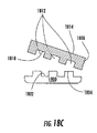
いくつかの実施態様において、本開示の主題はパターン形成プロトン交換膜の製造方法を提供する。それらの一実施態様は図1A〜1Bに提供される。
ここで、図1Aを参照すると、パターン基板、例えば型100が提供される。型100は、無機材料、有機材料、及びそれらの組合せからなる群から選択される材料を含む。いくつかの実施態様において、型100は、予め定めた幾何形状102を有し、予め定めた幾何形状102は巨視的領域104を有する。例えば、図1Aに示すように、予め定めた幾何形状102は、第1平坦面108を有する矩形基板106を含み、第1平坦面108は、図1Aに第1平坦面108から展延する複数のペグとして示される複数の構造形状110をさらに含む。
(II Process for Producing Pattern-Forming Proton Exchange Membrane)
In some embodiments, the presently disclosed subject matter provides a method of manufacturing a patterned proton exchange membrane. One embodiment of them is provided in FIGS.
Referring now to FIG. 1A, a patterned substrate, for example a
さらに、当業者であれば本開示を検討することによって理解するであろうように、複数の構造形状110は、ペグ、溝付きペグ、円筒形、パターン、壁、及び一体化された表面(図示されない)を非制限的に含む任意の形をとることができる。したがって、本開示の方法によって作られるプロトン交換膜は、様々な幾何形状に作ることができ、多くの通路を有することができ、及び/又は制御された、又は可変表面領域を含むことができる。
Further, as those skilled in the art will appreciate upon review of the present disclosure, the plurality of
いくつかの実施態様において、本開示の方法によって製造されるプロトン交換膜は、「巨視的表面」領域よりも大きな「活性表面」領域を有する。したがって、いくつかの実施態様において、予め定めた幾何形状102は、型100の巨視的領域104よりも大きな表面領域112を有する複数の構造110を含む。いくつかの実施態様において、複数の構造110は、型100の巨視的表面領域104の少なくとも約2倍〜約100倍の範囲の表面領域112を有する。いくつかの実施態様において、予め定めた幾何形状102は、型100の巨視的表面領域104の少なくとも2倍の表面領域112を有する複数の構造110を含む。いくつかの実施態様において、予め定めた幾何形状102は、型100の巨視的表面領域104の少なくとも5倍の表面領域112を有する複数の構造110を含む。いくつかの実施態様において、予め定めた幾何形状102は、型100の巨視的表面領域104の少なくとも20倍の表面領域112を有する複数の構造110を含む。いくつかの実施態様において、予め定めた幾何形状102は、型100の巨視的表面領域104の少なくとも80倍の表面領域112を有する複数の構造110を含む。
In some embodiments, the proton exchange membrane produced by the disclosed method has a “active surface” region that is larger than a “macroscopic surface” region. Accordingly, in some implementations, the
ここで図1A及び1Bを参照すれば、液体前駆体材料114は型100に接触する。液体前駆体材料114は上に開示した任意の液体前駆体材料を含むことができ、すなわち、液体前駆体材料はプロトン伝導性材料、プロトン伝導性材料への前駆体、及びそれらの組合せを含むことができる。液体前駆体材料114は処理工程Trによって処理されて図1Bに示す処理された液体前駆体材料116を形成する。
Referring now to FIGS. 1A and 1B, the
いくつかの実施態様において、処理工程Trは、硬化工程、化学的修飾工程、網目形成工程、溶媒蒸発工程、及びそれらの組合せからなる群から選択される工程を含む。いくつかの実施態様において、硬化工程は熱工程、光化学工程、及び照射工程からなる群から選択される工程を含む。さらに、いくつかの実施態様において、照射工程は液体材料を放射線で照射することを含み、放射線はガンマ線、及び電子ビームからなる群から選択される。いくつかの実施態様において、化学修飾工程は架橋工程を含む。 In some embodiments, the processing step Tr comprises a step selected from the group consisting of a curing step, a chemical modification step, a network formation step, a solvent evaporation step, and combinations thereof. In some embodiments, the curing step includes a step selected from the group consisting of a thermal step, a photochemical step, and an irradiation step. Further, in some embodiments, the irradiating step includes irradiating the liquid material with radiation, wherein the radiation is selected from the group consisting of gamma rays and electron beams. In some embodiments, the chemical modification step includes a crosslinking step.
ここで図1Bを参照すれば、処理された液体前駆体材料116は型100から取り外されて、型100の複数の構造形状110に対応する複数の構造形状120を含む自立のプロトン交換膜118を提供する。いくつかの実施態様において、複数の構造110及び120は10mm未満の寸法122を有する。いくつかの実施態様において、複数の構造110及び120は1mm未満の寸法122を有する。いくつかの実施態様において、複数の構造110及び120は100μm未満の寸法122を有する。いくつかの実施態様において、複数の構造110及び120は10μm未満の寸法122を有する。いくつかの実施態様において、複数の構造110及び120は1μm未満の寸法122を有する。言い換えれば、いくつかの実施態様において、複数の構造110及び120を含む個々の構造は、約10mm未満〜約1μm未満の範囲の寸法の高さ、及び/又は約10nm〜約1μm未満の範囲の寸法の幅を有することができる。
Referring now to FIG. 1B, the treated
したがって、いくつかの実施態様において、本開示の主題はパターン形成ポリマー電解質の製造方法を提供し、この方法は、
(a)液体前駆体材料を、予め定めた幾何形状及び巨視的表面領域を含むパターン基板に接触させること、及び
(b)液体前駆体材料を処理してパターン形成ポリマー電解質を形成することを含む。
いくつかの実施態様において、該液体前駆体材料は、プロトン伝導性材料、プロトン伝導性材料への前駆体、及びそれらの組合せからなる群から選択される材料を含む。
Accordingly, in some embodiments, the presently disclosed subject matter provides a method of making a patterned polymer electrolyte, the method comprising:
(A) contacting the liquid precursor material with a patterned substrate comprising a predetermined geometry and macroscopic surface area; and (b) treating the liquid precursor material to form a patterned polymer electrolyte. .
In some embodiments, the liquid precursor material comprises a material selected from the group consisting of proton conducting materials, precursors to proton conducting materials, and combinations thereof.
いくつかの実施態様において、該パターン基板は、無機材料、有機材料及びそれらの組合せからなる群から選択される材料を含む。
いくつかの実施態様において、該予め定めた幾何形状は、非平坦幾何形状を含む。いくつかの実施態様において、該非平坦幾何形状は、約10mm未満〜約1mm以上の寸法、約1mm未満〜約100μm以上の寸法、約100μm未満〜10μm以上の寸法、約10μm未満〜約1μm以上の寸法、及び約1μm未満の寸法からなる群から選択される予め定めた寸法を有する形状を含む。
In some embodiments, the patterned substrate comprises a material selected from the group consisting of inorganic materials, organic materials, and combinations thereof.
In some embodiments, the predetermined geometry includes a non-flat geometry. In some embodiments, the non-planar geometry is less than about 10 mm to about 1 mm or more, less than about 1 mm to about 100 μm or more, less than about 100 μm to 10 μm or more, less than about 10 μm to about 1 μm or more. And a shape having a predetermined dimension selected from the group consisting of a dimension and a dimension of less than about 1 μm.
いくつかの実施態様において、該予め定めた幾何形状は、1層の触媒層及び膜電極組立て体を含む電極材料によって画定される。いくつかの実施態様において、該予め定めた幾何形状は、膜電極組立て体によって画定される。いくつかの実施態様において、該予め定めた幾何形状は、パターン、ペグ、壁、交互嵌合表面、及び巻き取り円筒からなる群から選択される構造を含む。 In some embodiments, the predetermined geometry is defined by an electrode material comprising a single catalyst layer and a membrane electrode assembly. In some embodiments, the predetermined geometry is defined by a membrane electrode assembly. In some embodiments, the predetermined geometry includes a structure selected from the group consisting of a pattern, a peg, a wall, an interdigitated surface, and a winding cylinder.
いくつかの実施態様において、該予め定めた幾何形状はパターン基板の巨視的表面領域よりも大きな表面領域を有する構造を含む。いくつかの実施態様において、構造はパターン基板の巨視的表面領域の少なくとも約2倍〜約100倍の範囲の表面領域を有する。
いくつかの実施態様において、液体前駆体材料の処理は、(a)硬化工程、(b)化学的修飾工程、(c)網目形成工程、(d)溶媒蒸発工程、及び(e)それらの組合せからなる群から選択される工程を含む。
In some embodiments, the predetermined geometry includes a structure having a surface area that is larger than the macroscopic surface area of the patterned substrate. In some embodiments, the structure has a surface area in the range of at least about 2 times to about 100 times the macroscopic surface area of the patterned substrate.
In some embodiments, the treatment of the liquid precursor material comprises (a) a curing step, (b) a chemical modification step, (c) a network formation step, (d) a solvent evaporation step, and (e) a combination thereof. A step selected from the group consisting of:
したがって、いくつかの実施態様において、本開示の主題は本開示の方法によって製造されるパターン形成プロトン交換膜を提供する。いくつかの実施態様において、該パターン形成プロトン交換膜は、約1500未満〜約1000を超える当量、約1000未満〜約800を超える当量、約800未満〜約500を超える当量、及び約500以下の当量からなる群から選択される当量を有する材料を含む。
いくつかの実施態様において、本開示の主題は、本開示のパターン形成プロトン交換膜を含む電気化学電池を提供する。いくつかの実施態様において、電気化学電池は燃料電池、クロル−アルカリ電池、及びバッテリーからなる群から選択される。
Accordingly, in some embodiments, the presently disclosed subject matter provides a patterned proton exchange membrane manufactured by the disclosed method. In some embodiments, the patterned proton exchange membrane has an equivalent weight of less than about 1500 to more than about 1000, less than about 1000 to more than about 800, less than about 800 to more than about 500, and about 500 or less. Including a material having an equivalent selected from the group consisting of equivalents.
In some embodiments, the presently disclosed subject matter provides an electrochemical cell that includes the patterned proton exchange membrane of the present disclosure. In some embodiments, the electrochemical cell is selected from the group consisting of a fuel cell, a chlor-alkali cell, and a battery.
本開示の方法によって製造されるプロトン交換膜の一例は図2A及び2Bに提供され、それぞれ、鮫肌パターンを有するプロトン交換膜(PEM)の加水分解前の走査電子顕微鏡写真、及び鮫肌パターンを有するプロトン交換膜(PEM)の加水分解後の走査電子顕微鏡写真を示す。鮫肌パターンは、実施例7に説明するようにして製造された。この特定の例の鮫肌パターン、すなわち直前に上で説明した構造の形状サイズは、幅約2μm、高さ約8μmである。鮫肌パターンを利用することによって、パターンPEMの表面領域は、同じ巨視的寸法の平坦なパターン形成されないPEMの表面領域よりも約5倍大きい。図2Aにおいて走査電子顕微鏡写真が示すように、本開示の方法によって高い再現性の構造形状が得られる。さらに、図2Bにおいて走査電子顕微鏡写真が示すように、パターンはPEMの加水分解の後膨潤するが構造形状はやはり明らかである。 An example of a proton exchange membrane produced by the method of the present disclosure is provided in FIGS. 2A and 2B, respectively, a scanning electron micrograph before hydrolysis of a proton exchange membrane (PEM) having a crust pattern, and a proton having a crust pattern. The scanning electron micrograph after the hydrolysis of an exchange membrane (PEM) is shown. The hull pattern was manufactured as described in Example 7. This particular example of the scabbard pattern, ie the shape size of the structure just described above, is about 2 μm wide and about 8 μm high. By utilizing the shark skin pattern, the surface area of the pattern PEM is approximately five times larger than the surface area of a flat, non-patterned PEM of the same macroscopic dimension. As shown in the scanning electron micrograph in FIG. 2A, a highly reproducible structural shape is obtained by the method of the present disclosure. Furthermore, as the scanning electron micrograph shows in FIG. 2B, the pattern swells after hydrolysis of the PEM, but the structural shape is still clear.
いくつかの実施態様において、型100の予め定めた幾何形状、例えば、図1Aの要素102、したがってその中に形成されるPEMの幾何形状は、以下で図10に提供されるように、触媒結合層及び/又は膜電極組立て体の電極材料によって画定される。さらに、本開示の液体前駆体材料、例えば図1Aの液体前駆体材料114は液体であるので、注ぐことが可能である。したがって、液体前駆体材料114は電極材料によって画定される構造などの既存の構造中に注ぐことができる。
In some embodiments, the pre-determined geometry of the
例えば、ここで図3A及び3Bを参照すれば、第1の電極材料300及び第2の電極材料302は、間隙304がその間に形成されるように空間的に動作可能に配置される。液体前駆体材料306は間隙304中に注がれる。液体前駆体材料306は上で開示した任意の液体前駆体材料を含むことができる。次いで、液体前駆体材料306は処理工程Trによって処理され、プロトン交換膜308を形成し、いくつかの実施態様において、第1の電極材料300と第2の電極材料302の間の機能的な位置に留まる。したがって、いくつかの実施態様において、液体前駆体材料、例えば306は、予め構成された空洞、例えば第1の電極材料300と第2の電極材料302の間に形成された間隙304中に直接注入され、処理工程Trが続く。
For example, referring now to FIGS. 3A and 3B, the
再び図3A及び3Bを参照すれば、いくつかの実施態様において、液体前駆体材料306が間隙304中に注がれる前に、第1の電極材料300は第1の触媒材料310で被覆され、第2の電極材料302は第2の触媒材料312で被覆される。
いくつかの実施態様において、プロトン交換膜308は1種の当量を有する材料を含み、当量は、約1500未満で約1000を超える当量、約1000未満で約800を超える当量、約800未満で約500を超える当量、及び約500以下の当量からなる群から選択される。完全に水和された状態で異なる当量を有する本開示の液体材料から製造された代表的なPEM導電率は、図4〜8に提供される。
Referring again to FIGS. 3A and 3B, in some embodiments, before the
In some embodiments, the
(III 当量の勾配を含むポリマー電解質の製造方法)
さらに、本明細書に開示される液体前駆体材料の合成方法を変化させて、組成物の勾配を生成させ、本開示のPEMの特性を微調整し性能を改善することができる。典型的に、現在のPEMは、エネルギー密度とメタノール透過率の兼ね合いをもたらす1つの特性である1種の当量(EW)を有する材料を含む。例えば、NAFION(登録商標)系の高当量PEMはメタノールの透過率がより低い。しかし、それらの材料は比較的導電率が低い。低EWのPEMは、比肩し得る成分のより高いEW材料のものより高い導電率値を与えるが、メタノール透過率が高くなり、エネルギー密度が劇的に低下する。
(III Method for Producing Polymer Electrolyte Including Equivalent Gradient)
Further, the method of synthesis of the liquid precursor material disclosed herein can be varied to produce a composition gradient, fine tune the properties of the disclosed PEM, and improve performance. Typically, current PEMs include materials with one equivalent (EW), which is one property that provides a balance between energy density and methanol permeability. For example, NAFION® high equivalent weight PEM has lower methanol permeability. However, these materials have a relatively low conductivity. Low EW PEMs give higher conductivity values than those of higher EW materials with comparable components, but higher methanol permeability and dramatically lower energy density.
本開示の主題は当量の勾配を有するPEMを提供する。本明細書に開示するEWの勾配で、両方の領域(メタノール透過率及び導電率)における最適の性能を得ることができる。例えば、より高いEWを有する材料をアノードに使用することによってメタノール透過率の低いPEMが提供されるが、PEMの断面全体により低いEWを有する材料を含むことはより高いエネルギー密度を提供する。 The subject matter of this disclosure provides a PEM having an equivalent slope. With the EW slope disclosed herein, optimal performance in both regions (methanol permeability and conductivity) can be obtained. For example, using a material with a higher EW for the anode provides a PEM with lower methanol permeability, but including a material with a lower EW across the cross-section of the PEM provides a higher energy density.
ここで図9Aを参照すれば、複数の液体材料902を有するプロトン交換膜900が開示される。この実施態様において、複数の液体材料902は複数の液体材料902a〜902fを含む。いくつかの実施態様において、液体材料902a〜902fは、高ガラス転移温度(Tg)のNAFION(登録商標)等の材料を含む。しかし、液体材料902a〜902fは高Tg材料に制限されず、いくつかの実施態様において、液体材料902a〜902fはフッ化又は過フッ化エラストマー系材料、又は本明細書に開示される任意の材料を含む。
Referring now to FIG. 9A, a
いくつかの実施態様において、各液体材料、例えば、902a、902b、902c、902d、902e、及び902fは異なる当量(例えば、それぞれEWa、EWb、EWc、EWd、EWe、及びEWf(図示されない))を有する。本明細書に用いられる用語「当量」は、酸官能基1当量を含む酸性材料の質量を指す。したがって、本明細書に開示されるポリマー電解質の当量は、ポリマー電解質中の酸基当量数をポリマー電解質の重量で除したものである。さらに、本明細書に用いられる用語「異なる当量」は他の当量、例えばEWbから約50g/モル異なる当量、例えばEWaを指す。例えば、約800の当量は約750の当量とは異なると考えられる。 In some embodiments, each liquid material, eg, 902a, 902b, 902c, 902d, 902e, and 902f, has a different equivalent weight (eg, EW a , EW b , EW c , EW d , EW e , and EW f, respectively). (Not shown). As used herein, the term “equivalent” refers to the mass of an acidic material containing one equivalent of acid functionality. Therefore, the equivalent amount of the polymer electrolyte disclosed in the present specification is the number of acid group equivalents in the polymer electrolyte divided by the weight of the polymer electrolyte. Further, as used herein, the term “different equivalents” refers to other equivalents, such as equivalents that differ from EW b by about 50 g / mole, such as EW a . For example, an equivalent of about 800 is considered different from an equivalent of about 750.
再び図9Aを参照すれば、アノード904に最も近接している液体材料、すなわち層902aは、液体材料902b〜902fに比べてより高いEWを有する。いくつかの実施態様において、液体材料902a〜902fの当量は、EWa>EWb>EWc>EWd>EWe>EWfの傾向に従い、カソード906に最も近接している液体材料902fは最も低い当量を有する。
Referring again to FIG. 9A, the liquid material closest to the
いくつかの実施態様において、液体材料902a、902b、902c、902d、902e、及び902fの少なくとも1つは1500以下の当量を有する。いくつかの実施態様において、液体材料902a、902b、902c、902d、902e、及び902fの少なくとも1つは1000以下の当量を有する。いくつかの実施態様において、液体材料902a、902b、902c、902d、902e、及び902fの少なくとも1つは800以下の当量を有する。いくつかの実施態様において、液体材料902a、902b、902c、902d、902e、及び902fの少なくとも1つは500以下の当量を有する。完全に水和された状態で異なる当量を有する本開示の液体材料から製造される代表的PEMの導電率は、図4〜8に提供される。
In some embodiments, at least one of the
ここで図9Bを参照すれば、いくつかの実施態様において、アノード904でのPEM900のメタノール透過率を低下させるために、高EW液体材料、例えば当量EWaを有する902aが、基板、例えばアノード904上に、例えば塗布又はスピンコートされて配置され、アノード904上に液体材料902aの層を形成し、続いて処理工程Trで処理して処理された液体材料908aを形成する。処理された液体材料908aは、より低いEWの液体材料、例えば当量EWbを有する902bで被覆され、次いでこれは処理されて処理された液体材料908b(図示されない)を形成する。この手順を必要なだけ繰り返して、当量の勾配、例えばEWa〜EWfを含むPEM900を形成する。したがって、いくつかの実施態様において、処理された液体材料、例えばカソード906に最も近接している908f(図示されない)は、最も低いEW、例えばEWfを有する。したがって、本開示の方法は、アノード904でのメタノール透過率を低下させ、PEM900の断面を通るプロトン移動を容易に増加させて促進することができる。
Referring now to FIG. 9B, in some embodiments, to reduce the methanol permeability of the
したがって、いくつかの実施態様において、PEM900は複数のポリマー電解質層を含み、複数のポリマー電解質層は、第1の当量を有する材料を含む第1ポリマー電解質の少なくとも第1の層と、第2の当量を有する材料を含む第2ポリマー電解質の少なくとも第2の層とを含む。いくつかの実施態様において、複数のポリマー電解質層は当量の勾配を含む。
Accordingly, in some embodiments, the
したがって、いくつかの実施態様において、本開示の主題は複数の当量を含むポリマー電解質の製造方法を提供し、該方法は、
(a)第1の当量を有する第1の液体前駆体材料を基板に塗布すること、
(b)該第1の液体前駆体材料を処理して基板上に処理された液体前駆体材料の第1の層を形成すること、
(c)第2の当量を有する第2の液体前駆体材料を、該基板上の処理された液体前駆体材料の第1の層に塗布すること、及び
(d)該第2の液体前駆体材料を処理して、複数の当量を含むポリマー電解質を形成することを含む。
Accordingly, in some embodiments, the presently disclosed subject matter provides a method for producing a polymer electrolyte comprising a plurality of equivalents, the method comprising:
(A) applying a first liquid precursor material having a first equivalent to a substrate;
(B) treating the first liquid precursor material to form a treated first layer of liquid precursor material on a substrate;
(C) applying a second liquid precursor material having a second equivalent to the first layer of treated liquid precursor material on the substrate; and (d) the second liquid precursor. Treating the material to form a polymer electrolyte comprising a plurality of equivalents.
いくつかの実施態様において、該第1の液体前駆体材料及び該第2の液体前駆体材料は、プロトン伝導性材料、プロトン伝導性材料への前駆体、及びそれらの組合せからなる群から選択される。いくつかの実施態様において、該第1の当量は、第2の当量よりも大きい。
いくつかの実施態様において、該基板は、アノード及びカソードからなる群から選択される。いくつかの実施態様において、該第1の液体前駆体材料、該第2の液体前駆体材料、及び該複数の液体前駆体材料の処理は、硬化工程、化学的修飾工程、網目形成工程、溶媒蒸発工程、及びそれらの組合せからなる群から選択される。
In some embodiments, the first liquid precursor material and the second liquid precursor material are selected from the group consisting of proton conducting materials, precursors to proton conducting materials, and combinations thereof. The In some embodiments, the first equivalent is greater than the second equivalent.
In some embodiments, the substrate is selected from the group consisting of an anode and a cathode. In some embodiments, the processing of the first liquid precursor material, the second liquid precursor material, and the plurality of liquid precursor materials includes a curing step, a chemical modification step, a network formation step, a solvent Selected from the group consisting of evaporation steps, and combinations thereof.
いくつかの実施態様において、該方法は、ステップ(c)〜(d)を、複数の当量を含む予め定めた複数の液体前駆体材料で繰り返して、複数の当量を含むポリマー電解質を形成することを含み、該複数の液体前駆体材料は、プロトン伝導性材料、プロトン伝導性材料への前駆体、及びそれらの組合せからなる群から選択される。いくつかの実施態様において、該第2の当量は、該複数の当量よりも大きい。 In some embodiments, the method repeats steps (c)-(d) with a plurality of predetermined liquid precursor materials containing a plurality of equivalents to form a polymer electrolyte containing a plurality of equivalents. And the plurality of liquid precursor materials are selected from the group consisting of proton conducting materials, precursors to proton conducting materials, and combinations thereof. In some embodiments, the second equivalent is greater than the plurality of equivalents.
したがって、いくつかの実施態様において、本開示の主題は、本開示の方法によって製造される複数の当量を含むポリマー電解質を提供する。いくつかの実施態様において、本開示の主題は、当量の勾配を含む本開示のポリマー電解質を含む電気化学電池を提供する。いくつかの実施態様において、電気化学電池は燃料電池、クロル−アルカリ電池、及びバッテリーからなる群から選択される。
本開示のプロトン交換膜の性能は、中でも、導電率、エネルギー密度、耐久性、及び寿命を測定することによって評価することができる。
Accordingly, in some embodiments, the presently disclosed subject matter provides a polymer electrolyte comprising a plurality of equivalents produced by the methods of the present disclosure. In some embodiments, the presently disclosed subject matter provides an electrochemical cell that includes a polymer electrolyte of the present disclosure that includes a gradient of equivalents. In some embodiments, the electrochemical cell is selected from the group consisting of a fuel cell, a chlor-alkali cell, and a battery.
The performance of the proton exchange membrane of the present disclosure can be evaluated, among other things, by measuring conductivity, energy density, durability, and lifetime.
(IV 膜電極組立て体(MEA)の製造方法)
本開示の主題は、膜電極組立て体(MEA)の製造方法も提供する。いくつかの実施態様において、該膜電極組立て体の製造方法は、本明細書に説明される液体前駆体材料を用いる加工可能な触媒インク組成物の製造を含む。さらに、いくつかの実施態様において、該膜電極組立て体の製造方法は、本開示の方法によって製造されるプロトン交換膜を提供すること、プロトン交換膜を加工可能な触媒インク組成物で被覆して被覆されたプロトン交換膜を形成することを含み、かついくつかの実施態様において、該被覆されたプロトン交換膜に、電極材料を塗布することを含む。
(IV Membrane Electrode Assembly (MEA) Manufacturing Method)
The presently disclosed subject matter also provides a method of manufacturing a membrane electrode assembly (MEA). In some embodiments, the method of making the membrane electrode assembly includes making a processable catalyst ink composition using a liquid precursor material as described herein. Further, in some embodiments, the method of manufacturing the membrane electrode assembly includes providing a proton exchange membrane manufactured by the method of the present disclosure, coating the proton exchange membrane with a processable catalyst ink composition. Forming a coated proton exchange membrane, and in some embodiments, applying an electrode material to the coated proton exchange membrane.
(IV.A 加工可能な触媒インク組成物の製造方法)
いくつかの実施態様において、本開示の主題は加工可能な触媒インク組成物の製造方法を説明し、この方法は、
(a)液体前駆体材料を提供すること、及び
(b)該液体前駆体材料を触媒と混合して加工可能な触媒インク組成物を形成することを含む。
(IV.A Method for producing processable catalyst ink composition)
In some embodiments, the presently disclosed subject matter describes a method of making a processable catalyst ink composition, the method comprising:
(A) providing a liquid precursor material; and (b) mixing the liquid precursor material with a catalyst to form a processable catalyst ink composition.
いくつかの実施態様において、該液体前駆体材料は、液体ペルフルオロポリエーテル材料を含む。いくつかの実施態様において、該液体ペルフルオロポリエーテル材料は、末端基を含み、該末端基は硬化後化学的に安定である。いくつかの実施態様において、該化学的に安定な末端基は、アリール末端基及びフッ化ビニルエーテル末端基の1種から選択される。いくつかの実施態様において、該アリール末端基は、スチレニル末端基を含む。
いくつかの実施態様において、該方法は、液体前駆体材料をビニルモノマーなどのモノマー及び架橋剤と混合することをさらに含む。いくつかの実施態様において、該ビニルモノマーはプロトン伝導性化学種を含む。いくつかの実施態様において、該プロトン伝導性化学種は酸性材料及び酸性材料への前駆体の1種から選択される。
In some embodiments, the liquid precursor material comprises a liquid perfluoropolyether material. In some embodiments, the liquid perfluoropolyether material includes end groups that are chemically stable after curing. In some embodiments, the chemically stable end group is selected from one of an aryl end group and a fluorinated vinyl ether end group. In some embodiments, the aryl end group comprises a styrenyl end group.
In some embodiments, the method further comprises mixing the liquid precursor material with a monomer such as a vinyl monomer and a crosslinker. In some embodiments, the vinyl monomer comprises a proton conducting species. In some embodiments, the proton conducting species is selected from one of acidic materials and precursors to acidic materials.
いくつかの実施態様において、該加工可能な触媒インク組成物は、触媒を含む。いくつかの実施態様において、該触媒は、白金、ルテニウム、モリブデン、クロム、及びそれらの組合せからなる群から選択される金属を含む。いくつかの実施態様において、該触媒は、白金触媒及び白金合金触媒の1種から選択される。いくつかの実施態様において、該加工可能な触媒インク組成物は電極材料を含む。いくつかの実施態様において、該電極材料はカーボンブラックを含む。 In some embodiments, the processable catalyst ink composition comprises a catalyst. In some embodiments, the catalyst comprises a metal selected from the group consisting of platinum, ruthenium, molybdenum, chromium, and combinations thereof. In some embodiments, the catalyst is selected from one of a platinum catalyst and a platinum alloy catalyst. In some embodiments, the processable catalyst ink composition includes an electrode material. In some embodiments, the electrode material comprises carbon black.
いくつかの実施態様において、該方法は、該加工可能な触媒インク組成物の処理を含む。いくつかの実施態様において、該加工可能な触媒インク組成物の処理は、硬化工程、化学的修飾工程、網目形成工程、溶媒蒸発工程、及びそれらの組合せからなる群から選択される処理工程を含む。
したがって、いくつかの実施態様において、本開示の主題は、本明細書に説明される方法によって製造される加工可能な触媒インク組成物を提供する。
In some embodiments, the method includes treatment of the processable catalyst ink composition. In some embodiments, the processing of the processable catalyst ink composition comprises a processing step selected from the group consisting of a curing step, a chemical modification step, a network formation step, a solvent evaporation step, and combinations thereof. .
Accordingly, in some embodiments, the presently disclosed subject matter provides processable catalyst ink compositions made by the methods described herein.
(IV.B 加工可能な触媒インク組成物を基板へ塗布する方法)
いくつかの実施態様において、本開示の主題は、加工可能な触媒インク組成物を基板へ塗布する方法を提供する。いくつかの実施態様において、該基板は電極材料を含む。いくつかの実施態様において、該基板はプロトン交換膜を含む。
ここで図10Aを参照すれば、いくつかの実施態様において、直前に上で説明した加工可能な触媒インク組成物1000は電極材料1002上に塗布される。いくつかの実施態様において、電極材料1002はカーボン布を含む。いくつかの実施態様において、電極材料1002はカーボン紙を含む。続いて、加工可能な触媒インク組成物1000は、処理工程Trによって処理されて触媒結合層(図示されない)を形成し、電極材料1002との良好な接触を提供する。
(IV.B Method of Applying Processable Catalyst Ink Composition to Substrate)
In some embodiments, the presently disclosed subject matter provides a method of applying a processable catalyst ink composition to a substrate. In some embodiments, the substrate includes an electrode material. In some embodiments, the substrate comprises a proton exchange membrane.
Referring now to FIG. 10A, in some embodiments, the processable
ここで図10Bを参照すれば、いくつかの実施態様において、直前に上で説明した加工可能な触媒インク組成物1000はパターン形成プロトン交換膜1004に塗布される。続いて、加工可能な触媒インク組成物1000は処理工程Trによって処理されて触媒結合層(図示されない)を形成し、プロトン交換膜1004との良好な接触を提供する。
電極1002及びプロトン交換膜1004の1種又は両方を塗布するために用いられる方法は、化学気相成長法(CVD)、電子噴霧、電場堆積、rf−プラズマ強化CVD、火炎噴霧堆積、インクジェット印刷、又はパルスレーザー堆積を含む群から選択することができるが、これらに限定されない。いくつかの実施態様において、該方法は、該加工可能な触媒インク組成物の処理を含む。いくつかの実施態様において、該加工可能な触媒インク組成物の処理は、硬化工程、化学的修飾工程、網目形成工程、溶媒蒸発工程、及びそれらの組合せからなる群から選択される処理工程を含む。
Referring now to FIG. 10B, in some embodiments, the processable
The methods used to apply one or both of
本開示の主題は、異なる膜電極組立て体に使用するために独立に実施することができる。すなわち、1つの膜電極組立て体において、本開示の主題は電極材料を被覆するのに用いることができるが、他の膜電極組立て体において、本開示の主題はプロトン交換膜を被覆するのに用いることができる。さらに、これらの方法の両方とも、例えばそれぞれ図10A及び10Bに説明した方法は、同じ膜電極組立て体の製造に用いることができる。 The subject matter of this disclosure can be implemented independently for use with different membrane electrode assemblies. That is, in one membrane electrode assembly, the presently disclosed subject matter can be used to coat an electrode material, while in other membrane electrode assemblies, the presently disclosed subject matter can be used to coat a proton exchange membrane. be able to. Furthermore, both of these methods, for example, the methods described in FIGS. 10A and 10B, respectively, can be used to manufacture the same membrane electrode assembly.
(IV.C プロトン交換膜の整合的被覆方法)
いくつかの実施態様において、本開示の主題は、加工可能な触媒インク組成物及び電極材料の少なくとも1種でプロトン交換膜を整合的に被覆する方法を提供する。「整合的な被覆」は、例えば該加工可能な触媒インク組成物及び/又は電極材料の被覆が、例えば、プロトン交換膜の形状と導電的に接触し、それによって、その形状の幾何形状に整合することを意味する。
(IV.C Consistent Coating Method of Proton Exchange Membrane)
In some embodiments, the presently disclosed subject matter provides a method for consistently coating a proton exchange membrane with at least one of a processable catalyst ink composition and an electrode material. “Consistent coating” means, for example, that the coating of the processable catalyst ink composition and / or electrode material is in conductive contact with, for example, the shape of the proton exchange membrane, thereby matching the geometry of the shape. It means to do.
ここで図11Aを参照すれば、いくつかの実施態様において、パターンPEM1100は加工可能な触媒インク組成物1102で整合的に被覆され、続いて、カーボンブラックなどの電極材料1104で被覆され、電極材料1104の平坦面1106を形成する。いくつかの実施態様において、加工可能な触媒インク組成物1102は、次いで処理工程Trによって処理される。膜電極組立て体(図示されない)に動作可能に配置されるとき、該電極材料の平坦化被覆は、該膜電極組立て体が少なくとも一方の側に平坦表面を有することを可能にする。
Referring now to FIG. 11A, in some embodiments, the
ここで図11Bを参照すれば、いくつかの実施態様において、パターンPEM1100は加工可能な触媒インク組成物1102で整合的に被覆され、続いて、電極材料1104で被覆されて、電極材料1104の整合性表面1108を形成する。いくつかの実施態様において、加工可能な触媒インク組成物1102は、次いで処理工程Trによって処理される。
ここで図11Cを参照すれば、いくつかの実施態様において、パターンPEM1100は加工可能な触媒インク組成物1102で整合的に被覆されて、加工可能な触媒インク組成物1102の平坦表面1110を形成する。このステップに続いて電極材料1104で被覆されて、電極材料1104の平坦面1106を形成する。いくつかの実施態様において、加工可能な触媒インク組成物1102は、次いで処理工程Trによって処理される。膜電極組立て体(図示されない)に動作可能に配置されるとき、該電極材料の平坦化被覆は、該膜電極組立て体が少なくとも一方の側に平坦表面を有することを可能にする。
Referring now to FIG. 11B, in some embodiments, the
Referring now to FIG. 11C, in some embodiments, the
したがって、いくつかの実施態様において、該方法は、該加工可能な触媒インク組成物をプロトン交換膜及び電極材料の少なくとも1種に整合的に塗布することを含む。
例として、電子噴霧堆積技術を用いて触媒で整合的に被覆されたパターンPEM走査電子顕微鏡写真を図12A及び12Bに示す。さらに、蒸着堆積技術を用いて触媒で整合的に被覆されたパターンPEM走査電子顕微鏡写真を図13に示す。これらの各PEMの製造は実施例8に説明される。
Accordingly, in some embodiments, the method includes consistently applying the processable catalyst ink composition to at least one of a proton exchange membrane and an electrode material.
As an example, patterned PEM scanning electron micrographs consistently coated with a catalyst using an electrospray deposition technique are shown in FIGS. 12A and 12B. Further, FIG. 13 shows a pattern PEM scanning electron micrograph that is consistently coated with a catalyst using vapor deposition techniques. The manufacture of each of these PEMs is described in Example 8.
(IV.D 膜電極組立て体(MEA)の製造方法)
本開示の主題は、膜電極組立て体の製造方法を提供する。いくつかの実施態様において、該膜電極組立て体の製造方法は、プロトン交換膜の製造、加工可能な触媒インク組成物の製造、加工可能な触媒インク組成物の基板上への塗布、及びプロトン交換膜の整合的被覆の少なくとも1つの本開示の方法を含む。
(IV.D Manufacturing Method of Membrane Electrode Assembly (MEA))
The presently disclosed subject matter provides a method of manufacturing a membrane electrode assembly. In some embodiments, the method of manufacturing the membrane electrode assembly includes manufacturing a proton exchange membrane, manufacturing a processable catalyst ink composition, applying a processable catalyst ink composition on a substrate, and proton exchange. Including at least one method of the present disclosure for conformal coating of the membrane.
したがって、いくつかの実施態様において、膜電極組立て体の形成方法は、
(a)本明細書に説明される液体前駆体材料から製造されたプロトン交換膜を提供すること、
(b)第1の触媒材料及び第2の触媒材料を提供すること、
(c)第1の電極材料及び第2の電極材料を提供すること、及び
(d)該プロトン交換膜、該第1及び第2の触媒材料、並びに該第1及び第2の電極材料を、導電連絡を保って動作可能に配置して、膜電極組立て体を形成することを含む。
Thus, in some embodiments, a method of forming a membrane electrode assembly includes:
(A) providing a proton exchange membrane made from the liquid precursor material described herein;
(B) providing a first catalyst material and a second catalyst material;
(C) providing a first electrode material and a second electrode material; and (d) the proton exchange membrane, the first and second catalyst materials, and the first and second electrode materials, Operatively placing in conductive communication and forming a membrane electrode assembly.
ここで図14Aを参照すれば、本開示の膜電極組立て体の形成方法の一実施態様が提供される。図14Aの参照を続ければ、プロトン交換膜1400が提供される。いくつかの実施態様において、プロトン交換膜1400は図14Aに示した三次元幾何形状を含む。いくつかの実施態様において、第1の触媒材料1402及び第2の触媒材料1404はプロトン交換膜1400と整合的に接触させる。第1の電極材料1406は、第1の触媒材料1402と整合的に接触させる。第2の電極材料1408は、第2の触媒材料1404と接触させる。いくつかの実施態様において、第1の電極材料1406及び第2の電極材料1408は平坦な幾何形状を含む。いくつかの実施態様において、膜電極組立て体の部品は処理工程Trによって処理され、部品間の良好な接触と機械的な安定性を提供することができる。
Referring now to FIG. 14A, one embodiment of a method for forming a membrane electrode assembly of the present disclosure is provided. Continuing to refer to FIG. 14A, a
したがって、本開示の主題は、三次元プロトン交換膜及び整合的に触媒装填された二次元電極を含む電極組立て体を提供する。三次元とは、例えば、プロトン交換膜が平坦表面から展延する形状を含むことを意味する(例えば、図1Bの複数の構造形状120を参照されたい)。二次元とは、例えば、電極材料がプロトン交換膜と導電連絡する平坦表面を含むことを意味する(例えば、図14Aの第1の電極材料1406及び第2の電極材料1408を参照されたい)。
Accordingly, the presently disclosed subject matter provides an electrode assembly that includes a three dimensional proton exchange membrane and a consistently catalyst loaded two dimensional electrode. Three-dimensional means, for example, that the proton exchange membrane includes a shape that extends from a flat surface (see, for example, multiple
ここで図14Bを参照すれば、プロトン交換膜1400が提供される。いくつかの実施態様において、プロトン交換膜1400は図14Bに示した三次元幾何形状を含み、三次元幾何形状は複数の窪み1410を含む。いくつかの実施態様において、第1の触媒材料1412及び第2の触媒材料1414は窪み1410内に動作可能に配置される。第1の電極材料1406は、第1の触媒材料1412と整合的に接触させる。第2の電極材料1408は、第2の触媒材料1414と整合的に接触させる。いくつかの実施態様において、第1の電極材料1406及び第2の電極材料1408は平坦な二次元の幾何形状を含む。いくつかの実施態様において、該膜電極組立て体の部品は、処理工程Trによって処理され、部品間の良好な接触と機械的な安定性を提供することができる。したがって、本開示の主題は、三次元プロトン交換膜及び非整合的に触媒を装填した二次元電極を含む膜電極組立て体を提供する。
Referring now to FIG. 14B, a
ここで図15を参照すると、プロトン交換膜1500が提供される。いくつかの実施態様において、プロトン交換膜1500は複数の窪み1502を含む三次元幾何形状を含む。いくつかの実施態様において、第1の触媒材料1504及び第2の触媒材料1506はプロトン交換膜1500と整合的に接触する。いくつかの実施態様において、第1の電極材料1508は窪み1502内に配置され、第1の触媒材料1504と動作可能に接触する。いくつかの実施態様において、第2の電極材料1510は窪み1502内に配置され、触媒材料1506と動作可能に接触する。いくつかの実施態様において、該膜電極組立て体の部品は、処理工程Trによって処理され、部品間の良好な接触と機械的な安定性を提供することができる。したがって、本開示の主題は、三次元プロトン交換膜及び整合的に触媒を装填した三次元電極材料を含む三次元膜電極組立て体を提供する。
Referring now to FIG. 15, a
いくつかの実施態様において、該プロトン交換膜、例えば図14A及び14Bの1400、図15の1500は、本明細書に説明される方法によって実施される。いくつかの実施態様において、該プロトン交換膜は、液体前駆体材料を2個の電極材料、例えば図15の第1の電極材料1508と第2の電極材料1510の間に動作可能に配置し、次いで液体前駆体材料を処理することによって形成される。
In some embodiments, the proton exchange membrane, such as 1400 in FIGS. 14A and 14B, 1500 in FIG. 15, is implemented by the methods described herein. In some embodiments, the proton exchange membrane operably places a liquid precursor material between two electrode materials, eg, the
したがって、いくつかの実施態様において、本開示の主題は、膜電極組立て体の製造方法を提供し、この方法は、
(a)第1の電極材料を提供すること、
(b)第2の電極材料を提供すること、
(c)該第1の電極材料と該第2の電極材料との間に間隙が形成されるように、該第1の電極材料と該第2の電極材料とを空間的に配置すること、
(d)該第1の電極材料と該第2の電極材料との間の間隙に液体前駆体材料を配置すること、及び
(e)該液体前駆体材料を処理して膜電極組立て体を形成することを含む。
Accordingly, in some embodiments, the presently disclosed subject matter provides a method of manufacturing a membrane electrode assembly, the method comprising:
(A) providing a first electrode material;
(B) providing a second electrode material;
(C) spatially disposing the first electrode material and the second electrode material such that a gap is formed between the first electrode material and the second electrode material;
(D) disposing a liquid precursor material in a gap between the first electrode material and the second electrode material; and (e) treating the liquid precursor material to form a membrane electrode assembly. Including doing.
いくつかの実施態様において、該液体前駆体材料はプロトン伝導性材料、プロトン伝導性材料への前駆体、及びそれらの組合せからなる群から選択される。
いくつかの実施態様において、この方法は、
(a)該第1の電極材料を第1の触媒材料に接触させること、
(b)該第2の電極材料を第2の触媒材料に接触させること、及び
(c)該第1の電極材料と該第2の電極材料とが互いに面し、該第1の電極材料と該第2の電極材料との間に間隙が形成されるように、該第1の電極材料と該第2の電極材料とを空間的に配置することを含む。
In some embodiments, the liquid precursor material is selected from the group consisting of proton conducting materials, precursors to proton conducting materials, and combinations thereof.
In some embodiments, the method comprises:
(A) contacting the first electrode material with a first catalyst material;
(B) contacting the second electrode material with a second catalyst material; and (c) the first electrode material and the second electrode material face each other, and the first electrode material and Spatially arranging the first electrode material and the second electrode material such that a gap is formed between the second electrode material and the second electrode material.
さらに、いくつかの実施態様において、該第1の触媒材料及び該第2の触媒材料の少なくとも1種は、加工可能な触媒インク組成物を含む。いくつかの実施態様において、該方法は、該加工可能な触媒インク組成物を該プロトン交換膜に塗布することをさらに含む。いくつかの実施態様において、該方法は、該加工可能な触媒インク組成物を、該第1及び第2の電極材料の少なくとも1種に塗布することを含む。いくつかの実施態様において、該方法は、該加工可能な触媒インク組成物を該プロトン交換膜、及び該第1の電極材料と該第2の電極材料との少なくとも1種に塗布することを含む。 Further, in some embodiments, at least one of the first catalyst material and the second catalyst material comprises a processable catalyst ink composition. In some embodiments, the method further comprises applying the processable catalyst ink composition to the proton exchange membrane. In some embodiments, the method includes applying the processable catalyst ink composition to at least one of the first and second electrode materials. In some embodiments, the method comprises applying the processable catalyst ink composition to the proton exchange membrane and at least one of the first electrode material and the second electrode material. .
いくつかの実施態様において、該加工可能な触媒インク組成物は、化学気相成長(CVD)工程、電子噴霧工程、電場堆積工程、rf−プラズマ強化CVD工程、火炎噴霧堆積工程、インクジェット印刷工程、及びパルスレーザー堆積工程を非制限的に含む群から選択される工程によって塗布される。 In some embodiments, the processable catalyst ink composition comprises a chemical vapor deposition (CVD) process, an electrospray process, an electric field deposition process, an rf-plasma enhanced CVD process, a flame spray deposition process, an inkjet printing process, And by a process selected from the group including, but not limited to, a pulsed laser deposition process.
いくつかの実施態様において、該電極材料は、カーボン布、カーボン紙、カーボンブラックからなる群から選択される。いくつかの実施態様において、該電極材料はパターン電極材料を含む。
したがって、いくつかの実施態様において、本開示の主題は、本明細書に説明される方法によって製造される膜電極組立て体(MEA)を提供する。
In some embodiments, the electrode material is selected from the group consisting of carbon cloth, carbon paper, carbon black. In some embodiments, the electrode material comprises a patterned electrode material.
Accordingly, in some embodiments, the presently disclosed subject matter provides a membrane electrode assembly (MEA) manufactured by the methods described herein.
いくつかの実施態様において、その内部に電極材料が動作可能に配置される電気化学電池のエネルギー密度を増加させるため、該電極材料、例えば、カーボン布、カーボン紙、及び/又はカーボンブラックを処理してその表面積を増加させる。ここで図16を参照すれば、電極材料1600が提供される。電極材料1600は、従来のリソグラフ技術(図示されない)を用いてパターン形成して、又は電子ビーム、例えば図16のエッチング剤EAを用いて直接パターン形成して、パターン電極材料1602を形成することができる。いくつかの実施態様において、電極材料1600は、例えば、電子ビームリソグラフに用いるためのフォトレジスト1604をさらに含むことができる。いくつかの実施態様において、例えば酸素反応性イオンエッチングなどのプラズマエッチングに用いるために、マスク1606を提供することができる。
In some embodiments, the electrode material, such as carbon cloth, carbon paper, and / or carbon black, is treated to increase the energy density of an electrochemical cell in which the electrode material is operably disposed. Increase its surface area. Referring now to FIG. 16, an
したがって、いくつかの実施態様において、該電極材料は、
(a)リソグラフ工程、
(b)直接電子ビーム工程、
(c)フォトレジストを用いる電子ビームリソグラフ工程、
(d)マスクを用いるプラズマエッチング工程
を非制限的に含む群から選択される工程によってパターン形成される。
いくつかの実施態様において、プラズマエッチング工程は酸素反応性イオンエッチング工程を含む。
Thus, in some embodiments, the electrode material is
(A) lithographic process;
(B) a direct electron beam process;
(C) an electron beam lithographic process using a photoresist;
(D) A pattern is formed by a process selected from the group including, but not limited to, a plasma etching process using a mask.
In some embodiments, the plasma etching process includes an oxygen reactive ion etching process.
(V. 電気化学電池の形成方法)
いくつかの実施態様において、本開示の主題は、燃料電池などの電気化学電池の形成方法を提供する。ここで図17Aを参照すれば、プロトン交換膜1700が提供される。プロトン交換膜1700は本明細書に説明される方法によって本開示の液体前駆体材料から製造することができる。プロトン交換膜1700は、第1の触媒材料1702と第2の触媒材料1704の間に動作可能に配置され接触する。いくつかの実施態様において、第1の触媒材料1702及び第2の触媒材料1704は、各々独立に白金、ルテニウム、モリブデン、クロム、及びそれらの組合せからなる群から選択される金属を含む。
(V. Method for forming electrochemical cell)
In some embodiments, the presently disclosed subject matter provides a method for forming an electrochemical cell, such as a fuel cell. Referring now to FIG. 17A, a
図17Aの参照を続ければ、第1の触媒材料1702は第1の電極材料1706と動作可能に接触する。いくつかの実施態様において、第1の電極材料1706は第1表面1706a及び第2表面1706bを含む。したがって、いくつかの実施態様において、第1表面1706aと第2表面1706bとの少なくとも1種は、第1の触媒材料1702と動作可能に接触する。いくつかの実施態様において、第1表面1706aと第2表面1706bとの少なくとも1種は、第1の触媒材料1702で被覆される。いくつかの実施態様において、第1表面1706aと第2表面1706bとの少なくとも1種は、第1の触媒材料1702で含浸される。
With continued reference to FIG. 17A, the
図17Aの参照を続ければ、第2の触媒材料1704は、第2の電極材料1708と動作可能に接触する。いくつかの実施態様において、第2の電極材料1708は、第1表面1708a及び第2表面1708bを含む。したがって、いくつかの実施態様において、第1表面1708aと第2表面1708bとの少なくとも1種は、第2の触媒材料1704と動作可能に接触する。いくつかの実施態様において、第1表面1708aと第2表面1708bとの少なくとも1種は、第2の触媒材料1704で被覆される。いくつかの実施態様において、第1表面1708aと第2表面1708bとの少なくとも1種は、第2の触媒材料1704で含浸される。
Continuing with reference to FIG. 17A, the second
図17Aの参照を続ければ、したがって、膜電極組立て体1710は、プロトン交換膜1700、第1の触媒層1702、第1の電極材料1706、第2の触媒層1704、及び第2の電極材料1708を動作可能に配置することによって形成される。膜電極組立て体1710は、燃料電池などの電気化学電池中に動作可能に配置される。
図17Aの参照を続ければ、第1外部層1712及び第2外部層1714が提供される。いくつかの実施態様において、第1外部層1712及び第2外部層1714は本明細書に説明されるペルフルオロポリエーテル(PFPE)材料から構成される。第1外部層1712は、複数のマイクロ流体チャンネル1716をさらに含み、そこを通して燃料F1を導入することができ、第2外部層1714は、複数のマイクロ流体チャンネル1718をさらに含み、そこを通して燃料F2を導入することができる。
Continuing with reference to FIG. 17A, therefore, the
Continuing to refer to FIG. 17A, a first
いくつかの実施態様において、第1の電極材料1706はアノードを含み、燃料F1と流体連絡し、F1は、いくつかの実施態様において、アノード燃料を含む。いくつかの実施態様において、アノード燃料、例えば燃料F1はH2、アルカン、アルキルアルコール、ジアルキルエーテル、及びグリコールからなる群から選択される。いくつかの実施態様において、該アルカンは、メタン、エタン、プロパン、及びブタンからなる群から選択される。いくつかの実施態様において、該アルキルアルコールは、メタノール、エタノール、プロパノール、ブタノール、ペンタノール、ヘキサノールからなる群から選択される。いくつかの実施態様において、該アルキルアルコールは、メタノールを含む。いくつかの実施態様において、該ジアルキルエーテルは、ジメチルエーテルを含む。いくつかの実施態様において、該グリコールは、エチレングリコールを含む。
In some embodiments, the
いくつかの実施態様において、第2の電極材料1708は、カソードを含み、燃料F2と流体連絡し、F2はいくつかの実施態様において、カソード燃料を含む。いくつかの実施態様において、該カソード燃料、例えば燃料F2は空気などの酸素(O2)含有ガスを含む。いくつかの実施態様において、該カソード燃料は、空気/水混合物を含む。
いくつかの実施態様において、該電気化学電池は、少なくとも1個の電気的出力接続Eoを含む。
In some embodiments, the
In some embodiments, the electrochemical cell includes at least one electrical output connection E o .
ここで図17Bを参照すれば、いくつかの実施態様において、複数のマイクロ流体チャンネル1716は、少なくとも1個の入口開口1720を含む。いくつかの実施態様において、入口開口1720は、燃料源1722と流体連絡する。いくつかの実施態様において、燃料源1722は、燃料F1を含む。いくつかの実施態様において、燃料F1はアノード燃料及びカソ−ド燃料からなる群から選択される。
図17Bの参照を続ければ、いくつかの実施態様において、複数のマイクロ流体チャンネル1718、は少なくとも1個の入口開口1724を含む。いくつかの実施態様において、入口開口1724は、燃料源1726と流体連絡する。いくつかの実施態様において、燃料源1726は、燃料F2を含む。いくつかの実施態様において、燃料F2は、アノード燃料及びカソ−ド燃料からなる群から選択される。
Referring now to FIG. 17B, in some embodiments, the plurality of
Continuing with reference to FIG. 17B, in some embodiments, the plurality of
いくつかの実施態様において、複数のマイクロ流体チャンネル1716は出口開口1728を含む。いくつかの実施態様において、出口開口1728は、燃料再循環チャンネル1730と流体連絡する。いくつかの実施態様において、出口開口は、廃棄物排出口1732と流体接続する。
いくつかの実施態様において、複数のマイクロ流体チャンネル1718は出口開口1734を含む。いくつかの実施態様において、出口開口1734は燃料再循環チャンネル1736と流体連絡する。いくつかの実施態様において、出口開口は廃棄物排出口1738と流体接続する。
In some embodiments, the plurality of
In some embodiments, the plurality of
いくつかの実施態様において、複数のマイクロ流体チャンネル1716は複数のバルブ、例えば、1740a、1740b、1740cを含む。いくつかの実施態様において、複数のバルブ、1740a、1740b、1740cは、圧力駆動バルブ(図示されない)を含む。いくつかの実施態様において、複数のマイクロ流体チャンネル1718は複数のバルブ、例えば、1742a、1742b、1742cを含む。いくつかの実施態様において、複数のバルブ、1740a、1740b、1740cは、圧力駆動バルブ(図示されない)を含む。
いくつかの実施態様において、複数のマイクロ流体チャンネル1716及び複数のマイクロ流体チャンネル1718は、各々マイクロ流体チャンネル(図示されない)の網目を含む。
In some embodiments, the plurality of
In some embodiments, the plurality of
いくつかの実施態様において、マイクロ流体装置はソフトリソグラフ工程によって製造される。本明細書に用いられる用語「ソフトリソグラフ」は、弾性体スタンプを用いることによってマイクロメートル及びマイクロメートル以下の形状が基板に転写される工程を指す。ソフトリソグラフは、約100nmより小さな形状寸法を製造するために、従来のフォトリソグラフ工程の代替として出現した。本明細書に用いられる用語「ソフトリソグラフ」は、インプリントリソグラフ(IL)、レプリカ成型、マイクロコンタクト印刷(MCP)、キャピラリ中のマイクロ成型(MIMIC)、溶媒援用マイクロ成型(SAMIM)を非制限的に含むいくつかの工程を包含する。 In some embodiments, the microfluidic device is manufactured by a soft lithographic process. As used herein, the term “soft lithograph” refers to the process of transferring micrometer and sub-micrometer shapes to a substrate by using an elastic stamp. Soft lithographs have emerged as an alternative to conventional photolithographic processes to produce geometries smaller than about 100 nm. As used herein, the term “soft lithograph” refers to imprint lithography (IL), replica molding, micro contact printing (MCP), micro molding in capillaries (MIMIC), and solvent assisted micro molding (SAMIM). Including several steps.
ここで図18A〜18Cを参照すれば、複数のマイクロ流体チャンネルを含むペルフルオロポリエーテル(PFPE)材料の層を形成する本開示の方法の一実施態様の概要が示される。隆起した突起1804を含むパターン表面1802を有する基板1800が示される。したがって、基板1800のパターン表面1802は、パターンの形状を形成する少なくとも1個の隆起した突起1804を含む。いくつかの実施態様において、基板1800のパターン表面1802は、複雑なパターンを形成する複数の隆起した突起1804を含む。
Referring now to FIGS. 18A-18C, an overview of one embodiment of the disclosed method of forming a layer of perfluoropolyether (PFPE) material comprising a plurality of microfluidic channels is shown. A
図18Bで最善に見えるように、ポリマー前駆体1806は基板1800のパターン表面1802に配置される。ポリマー前駆体1806はペルフルオロポリエーテル(PFPE)を含むことができる。図18Bに示すように、ポリマー前駆体1806は、処理工程Tr、例えば紫外光での照射によって処理されて、図18Cに示すように、光硬化したペルフルオロポリエーテルのパターン層1808を形成する。
As best seen in FIG. 18B, the
図18Cに示すように、光硬化したペルフルオロポリエーテルのパターン層1808は、パターン層1808の底部表面に形成された窪み1810を含む。窪み1810の寸法は、基板1800のパターン表面1802の隆起した突起1804の寸法に一致する。いくつかの実施態様において、窪み1810は少なくとも1個のチャンネル1812を含み、本開示の主題のいくつかの実施態様において、マイクロ規模のチャンネルを含む。パターン層1808は基板1800のパターン表面1802から除去されてマイクロ流体装置1814を生成する。したがって、いくつかの実施態様において、該ソフトリソグラフ工程は、液体前駆体材料をパターン基板、例えばシリコンウェーハと接触させることを含む。いくつかの実施態様において、該工程は、該液体前駆体材料を処理して架橋ポリマーを形成することをさらに含む。いくつかの実施態様において、該処理工程は、硬化工程、化学的修飾工程、網目形成工程、及びそれらの組合せからなる群から選択される。
As shown in FIG. 18C, the photocured
いくつかの実施態様において、該工程は、該架橋ポリマーを該基板から除去し、それによって所望のパターンの「スタンプ」を作ることをさらに含む。
ポリ(ジメチルシロキサン)(PDMS)弾性体材料は、典型的にそれらのマイクロ流体装置に用いられる。しかし、該PDMS材料の膨潤は、マイクロメートルサイズの形状を崩壊させるため、直接メタノール燃料電池及び他の有機液体を含む燃料電池におけるその使用を制限する。さらに、該PDMS材料は典型的に酸及び塩基に不安定でもある。
In some embodiments, the process further comprises removing the crosslinked polymer from the substrate, thereby creating a “stamp” of the desired pattern.
Poly (dimethylsiloxane) (PDMS) elastomeric materials are typically used in these microfluidic devices. However, the swelling of the PDMS material collapses its micrometer-sized shape, thus limiting its use in direct methanol fuel cells and fuel cells containing other organic liquids. Furthermore, the PDMS material is typically also acid and base labile.
本開示の主題は、光硬化可能なPFPE材料を使用することによって、PDMS弾性体に伴う上記問題を全体的に又は部分的に対処する。いくつかの実施態様において、該PFPE材料は、フッ素化した官能化PFPE材料を含み、いくつかの実施態様において、液状の粘度を有し、典型的なフルオロポリマーの化学的抵抗性を示す堅牢な弾性体に硬化することができる。 The subject of the present disclosure addresses, in whole or in part, the above problems associated with PDMS elastomers by using a photocurable PFPE material. In some embodiments, the PFPE material comprises a fluorinated functionalized PFPE material, and in some embodiments has a liquid viscosity and is a robust material that exhibits the chemical resistance of typical fluoropolymers. It can be cured to an elastic body.
したがって、いくつかの実施態様において、本開示の主題は硬化したPFPE系材料を含む。いくつかの実施態様において、該硬化方法は、遊離ラジカル硬化方法を含む。いくつかの実施態様において、該遊離ラジカル硬化方法は、該PFPE樹脂に他のモノマー及びマクロモノマーを加えることをさらに含む。該PFPE樹脂に他のモノマー及びマクロモノマーを加えることは、モジュラス、曲げ強度、濡れ特性、透過率、接着、反応性を非制限的に含む物理的特性を制御可能にする。 Accordingly, in some embodiments, the presently disclosed subject matter includes a cured PFPE-based material. In some embodiments, the curing method comprises a free radical curing method. In some embodiments, the free radical curing method further comprises adding other monomers and macromonomers to the PFPE resin. Adding other monomers and macromonomers to the PFPE resin allows control of physical properties including, but not limited to modulus, flexural strength, wetting properties, permeability, adhesion, and reactivity.
(VI. 電気化学電池の運転方法)
また、本開示の主題は、燃料電池などの電気化学電池の運転方法を提供する。いくつかの実施態様において、該方法は、
(a)少なくとも1つのマイクロ流体チャンネルを含む少なくとも1層のペルフルオロポリエーテル(PFPE)材料を含む電気化学電池を提供すること、
(b)第1の電極反応物及び第2の電極反応物を該電気化学電池中に分配すること、及び
(c)該電気化学電池から電気出力を発生することを含む。
いくつかの実施態様において、該電気化学電池のプロトン交換膜は、本明細書に説明される液体前駆体材料から製造されたポリマー電解質を含む。
(VI. Electrochemical battery operation method)
The presently disclosed subject matter also provides a method of operating an electrochemical cell, such as a fuel cell. In some embodiments, the method comprises:
(A) providing an electrochemical cell comprising at least one layer of perfluoropolyether (PFPE) material comprising at least one microfluidic channel;
(B) distributing the first electrode reactant and the second electrode reactant into the electrochemical cell; and (c) generating electrical output from the electrochemical cell.
In some embodiments, the proton exchange membrane of the electrochemical cell includes a polymer electrolyte made from the liquid precursor material described herein.
いくつかの実施態様において、該第1の電極反応物は、H2、アルカン、アルキルアルコール、ジアルキルエーテル、及びグリコールからなる群から選択される。いくつかの実施態様において、該アルカンは、メタン、エタン、プロパン、及びブタンからなる群から選択される。いくつかの実施態様において、該アルキルアルコールは、メタノール、エタノール、プロパノール、ブタノール、ペンタノール、及びヘキサノールからなる群から選択される。いくつかの実施態様において、該アルキルアルコールは、メタノールを含む。いくつかの実施態様において、該ジアルキルエーテルは、ジメチルエーテルを含む。いくつかの実施態様において、該グリコールは、エチレングリコールを含む。いくつかの実施態様において、該第2の電極反応物は空気などの酸素(O2)含有ガスを含み、いくつかの実施態様において、空気/水混合物を含む。 In some embodiments, the first electrode reactant is selected from the group consisting of H 2 , alkanes, alkyl alcohols, dialkyl ethers, and glycols. In some embodiments, the alkane is selected from the group consisting of methane, ethane, propane, and butane. In some embodiments, the alkyl alcohol is selected from the group consisting of methanol, ethanol, propanol, butanol, pentanol, and hexanol. In some embodiments, the alkyl alcohol comprises methanol. In some embodiments, the dialkyl ether comprises dimethyl ether. In some embodiments, the glycol comprises ethylene glycol. In some embodiments, the second electrode reactant comprises an oxygen (O 2 ) containing gas, such as air, and in some embodiments, an air / water mixture.
いくつかの実施態様において、該方法は、電気化学電池によって発生した電気的出力を取り出すことを含む。いくつかの実施態様において、該電気的出力は約100ミリワット〜約20ワットの範囲である。
いくつかの実施態様において、該電気化学電池の運転方法は、装置に電気的エネルギーを供給することをさらに含む。いくつかの実施態様において、該装置は、据置型の装置を含む。いくつかの実施態様において、該据付装置は、発電機を含む。いくつかの実施態様において、該装置は、携帯装置を含む。いくつかの実施態様において、該携帯装置は、携帯発電機、携帯電気器具、電気工具、電子装置、鉄道又は交通信号、予備電源供給、個人用車両からなる群から選択される。いくつかの実施態様において、該電子装置は、消費者電子装置及び軍用電子装置の1種から選択される。いくつかの実施態様において、該装置は、自動車装置を含む。
In some embodiments, the method includes removing the electrical output generated by the electrochemical cell. In some embodiments, the electrical power ranges from about 100 milliwatts to about 20 watts.
In some embodiments, the method of operating the electrochemical cell further comprises supplying electrical energy to the device. In some embodiments, the device comprises a stationary device. In some embodiments, the installation device includes a generator. In some embodiments, the device includes a portable device. In some embodiments, the portable device is selected from the group consisting of a portable generator, portable appliance, electric tool, electronic device, rail or traffic signal, standby power supply, personal vehicle. In some embodiments, the electronic device is selected from one of consumer electronic devices and military electronic devices. In some embodiments, the device comprises a motor vehicle device.
(実施例)
以下の実施例は、本開示の主題の代表的な実施態様を実施する当業者に手引きを提供するために含まれている。本開示及び当技術分野の一般的な水準に照らして、当業者であれば、以下の実施例が単なる例示を意図するものであり、本開示の主題の範囲から逸脱することなく多くの変化、修正、及び変更を加えることができることを認識できる。
(Example)
The following examples are included to provide guidance to those skilled in the art practicing exemplary embodiments of the presently disclosed subject matter. In light of this disclosure and the general level of the art, those of ordinary skill in the art will appreciate that the following examples are intended to be illustrative only, and that many changes may be made without departing from the scope of the present subject matter. It can be appreciated that modifications and changes can be made.
(実施例1)
(架橋可能なPFPE液体前駆体の合成)
実施例1.1 スチレン結合を有する架橋可能なPFPE液体前駆体の合成
ポリ(テトラフルオロエチレン−co−ジフルオロエチレンオキシド)α,ωジオール(ZDOL)(PFPE、平均Mn=約3800g/モル)鎖の両端に、界面反応によってスチレン結合を加える。典型的な合成において、PFPE(20g、5.26ミリモル)、ソルカン(10mL)、及び硫酸水素テトラブチルアンモニウム(1.0g、2.95ミリモル)を丸底フラスコ中に加える。KOH(10g、0.18モル)を脱イオン水(20mL)に溶解し、次いで、水性KOH溶液を丸底フラスコに加える。4−ビニルベンジルクロリド(2mL、12.8ミリモル)を加えた後、反応混合物を45℃で48時間激しく攪拌する。生成物を0.22μmフィルターに通して、得られる褐色固体を取り除く。次いで、溶液を脱イオン水で3回抽出し、カーボンブラックと共に1時間攪拌してあらゆる不純物を除去する。混合物を0.22μmのフィルターを通してカーボンブラックを除去し、室温で真空乾燥して溶媒を除去する。得られる生成物(S−PFPE)は透明で高粘度の液体である。
Example 1
(Synthesis of crosslinkable PFPE liquid precursor)
Example 1.1 Synthesis of Crosslinkable PFPE Liquid Precursor with Styrene Bond Poly (tetrafluoroethylene-co-difluoroethylene oxide) α, ω diol (ZDOL) (PFPE, average Mn = about 3800 g / mol) on both ends of the chain In addition, styrene bonds are added by interfacial reaction. In a typical synthesis, PFPE (20 g, 5.26 mmol), solcan (10 mL), and tetrabutylammonium hydrogen sulfate (1.0 g, 2.95 mmol) are added into a round bottom flask. KOH (10 g, 0.18 mol) is dissolved in deionized water (20 mL) and then an aqueous KOH solution is added to the round bottom flask. After 4-vinylbenzyl chloride (2 mL, 12.8 mmol) is added, the reaction mixture is stirred vigorously at 45 ° C. for 48 hours. The product is passed through a 0.22 μm filter to remove the resulting brown solid. The solution is then extracted three times with deionized water and stirred with carbon black for 1 hour to remove any impurities. The mixture is passed through a 0.22 μm filter to remove carbon black and vacuum dried at room temperature to remove the solvent. The resulting product (S-PFPE) is a clear and highly viscous liquid.
実施例1.2 官能性PFPEの合成及び光硬化
官能性PFPEの合成及び光硬化の代表図スキームを、スキーム1に提供する。
Example 1.2 Synthesis and Photocuring of Functional PFPE A representative scheme for the synthesis and photocuring of functional PFPE is provided in
実施例1.3 代表的ペルフルオロポリエーテル
本開示の主題のペルフルオロポリエーテル材料は、以下の主鎖構造を含むペルフルオロポリエーテル材料を非制限的に含む。
Example 1.3 Representative Perfluoropolyethers Perfluoropolyether materials of the presently disclosed subject matter include, but are not limited to, perfluoropolyether materials comprising the following backbone structure:
(実施例2)
(架橋系の合成)
実施例2.1 概論
強酸と多官能性モノマーは、遊離ラジカル又は異なる化学反応機構によって架橋する。多官能性モノマーは、強酸とすることができ、少なくとも2種の官能性を有することができる。電気化学電池用途のためのこれらの架橋系に用いることのできる強酸の一例は、ペルフルオロ−2−(2−フルオロスルホニルエトキシ)プロピルビニルエーテル(PSEPVE)である。強酸又は多官能性モノマーとして機能することのできる他の超酸は、スルホンイミド系化合物である。
(Example 2)
(Synthesis of crosslinking system)
Example 2.1 General Strong acids and multifunctional monomers are cross-linked by free radicals or different chemical reaction mechanisms. The polyfunctional monomer can be a strong acid and can have at least two different functionalities. One example of a strong acid that can be used in these crosslinking systems for electrochemical cell applications is perfluoro-2- (2-fluorosulfonylethoxy) propyl vinyl ether (PSEPVE). Other superacids that can function as strong acids or multifunctional monomers are sulfonimide compounds.
強酸と多官能性モノマーを、アルゴン下、必要に応じてフッ素化又は過フッ素化溶媒と一緒に丸底フラスコ中で混合する。2種の化合物の割合は所望の架橋密度及び当量で変化する。温度及び反応時間などの反応条件は、特定の化合物及び混合の容易さに応じて変化させることができる。 The strong acid and the multifunctional monomer are mixed in a round bottom flask with argon, optionally with a fluorinated or perfluorinated solvent. The ratio of the two compounds varies with the desired crosslink density and equivalent weight. Reaction conditions such as temperature and reaction time can be varied depending on the particular compound and ease of mixing.
該反応混合物を含む液体前駆体をガラススライド又は型などのパターン基板上に注ぐ。標準的なスチール製スペーサを用いて膜の厚さを制御する。該液体前駆体は、UV光による照射で化学的に又は窒素パージ下で熱的に架橋する。化学的な架橋の機構は、使用される開始剤に依存する。架橋網目が製造されると、塩基及び酸を用いる加水分解によってあらゆる残りの伝導性部位が酸に変換し、プロトン伝導性を高める。 A liquid precursor containing the reaction mixture is poured onto a patterned substrate such as a glass slide or mold. Standard steel spacers are used to control the film thickness. The liquid precursor is crosslinked either chemically by irradiation with UV light or thermally under a nitrogen purge. The mechanism of chemical cross-linking depends on the initiator used. Once the cross-linked network is produced, hydrolysis with base and acid converts any remaining conductive sites to acid, increasing proton conductivity.
実施例2.2 フッ化ジビニルエーテルとしての多官能性モノマー
非伝導性の二官能性モノマーは、強酸と反応すると機械的に安定なプロトン伝導性網目をもたらす。4,4’−ビス(4−トリフルオロビニルオキシ)ビフェニル(化合物1)などの2個以上の官能性を有する市場で入手可能な化合物をPSEPVEなどの強酸と反応させる。液体前駆体の状態で、該反応混合物は表面/型の形状を持ち、不活性雰囲気中で、開始剤の添加によって遊離ラジカル的、熱的、又は光化学的に架橋する。
Example 2.2 Multifunctional Monomer as Fluorinated Divinyl Ether Non-conductive bifunctional monomers provide a mechanically stable proton conducting network when reacted with strong acids. A commercially available compound having two or more functionalities such as 4,4′-bis (4-trifluorovinyloxy) biphenyl (compound 1) is reacted with a strong acid such as PSEPVE. In the liquid precursor state, the reaction mixture has a surface / mould shape and crosslinks free radically, thermally, or photochemically in an inert atmosphere by addition of an initiator.
実施例2.3 トリス(トリフルオロビニル)ベンゼンとしての多官能性モノマー
液体前駆体は、架橋機構が実現可能であれば、パターン形成に適している。三官能性モノマーでの遊離ラジカル硬化は、強酸で硬化されるとき、プロトン伝導性に利用可能な化学的に架橋した網目を提供する。三官能性モノマーの一例は、トリス(α,β,β−トリフルオロビニル)ベンゼン(化合物2)であり、1,3,5−トリブロモベンゼンを用いて調製される(スキーム2参照)。また、スキーム2の出発物質は、強酸による後続の架橋のための三官能性モノマーを代表することができる。強酸の一例は、PSEPVEである。液体前駆体状態の反応混合物は実施例2.2に説明されるようにして架橋することができる。
Example 2.3 Multifunctional Monomer as Tris (trifluorovinyl) benzene Liquid precursors are suitable for pattern formation if a crosslinking mechanism is feasible. Free radical curing with trifunctional monomers provides a chemically crosslinked network that can be utilized for proton conductivity when cured with strong acids. An example of a trifunctional monomer is tris (α, β, β-trifluorovinyl) benzene (Compound 2), which is prepared using 1,3,5-tribromobenzene (see Scheme 2). The starting material of
実施例2.4 フッ化ジビニルエーテルスルホンイミドとしての多官能性モノマー
二官能性マクロモノマーは、超酸でもあり、PSEPVEなどの他の強酸と反応して伝導性の高い機械的に安定な網目が得られる。液体前駆体の形で、この反応は架橋前に任意の型の形状を取る。後続の架橋は表面積の大きい伝導性の高い膜をもたらす。二官能性マクロモノマーとして用いられる超酸の一例は、ビス(PSEPVE系)スルホンイミド(化合物3)であり、スルホンイミドの化学反応によって調製される(スキーム3及び4参照)。該反応混合物は、実施例2.2に説明した条件下で硬化することができる。
Example 2.4 Multifunctional Monomer as Fluorinated Divinyl Ether Sulfonimide The bifunctional macromonomer is also a superacid and reacts with other strong acids such as PSEPVE to produce a highly conductive and mechanically stable network. can get. In the form of a liquid precursor, this reaction takes any type of shape prior to crosslinking. Subsequent crosslinking results in a highly conductive film with a large surface area. One example of a superacid used as a bifunctional macromonomer is bis (PSEPVE-based) sulfonimide (Compound 3), which is prepared by a sulfonimide chemical reaction (see Schemes 3 and 4). The reaction mixture can be cured under the conditions described in Example 2.2.
実施例2.5 フッ化ビスビニルエーテルジスルホンイミドとしての多官能性モノマー
PSEPVEなどの強酸とジスルホニルフルオリドを用いて、この架橋可能な超酸モノマー(化合物4、スキーム6)を得るスルホンイミド化学反応を用いて、ビスビニルエーテルジスルホンイミドが調製される。ジスルホニルフルオリドは、α,ω−ジヨードペルフルオロアルカン(スキーム5)などのジヨードアルカンを用いて調製することができる。ビスビニルエーテルジスルホンイミドは、PSEPVEなどの他の強酸と反応して伝導性の高い膜を形成する。該反応物は、実施例2.2に説明した条件下で硬化することができる。
Example 2.5 Polyfunctional monomer as fluorinated bisvinyl ether disulfonimide Using a strong acid such as PSEPVE and disulfonyl fluoride, sulfonimide chemistry to obtain this crosslinkable superacid monomer (
(実施例3)
(架橋可能なターポリマーの合成)
実施例3.1 概論
フルオロオレフィン、強酸、及び低分子量の硬化部位モノマー(CSM)を含むターポリマーを重合する。フルオロオレフィンの一例は、テトラフルオロエチレン(TFE)であり、強酸としてペルフルオロ2−(2−フルオロスルホニルエトキシ)プロピルビニルエーテル(PSEPVE)を選択する。典型的な重合は40%固体を装填することができる。TFE系重合に選択される溶媒は任意に二酸化炭素(CO2)である。開始剤濃度によって所望の分子量を微調整する。より高い開始剤濃度はより低い比分子量をもたらし、より低い開始剤濃度はより高い比分子量をもたらすであろう。重合は熱開始剤によって遊離ラジカル的に行われる。反応時間は所望の変換によって変化する。重合は、通常フッ化エラストマー及び過フッ化エラストマー技術に用いられる硬化部位モノマーを用いて行うことが好ましい。例えば、硬化部位モノマーは、シアノビニルエーテル、臭素含有モノマー、臭素含有オレフィン、臭素含有ビニルエーテル、ヨウ素含有モノマー、ヨウ素含有オレフィン、ヨウ素含有ビニルエーテル、ニトリル基を有するフッ素含有オレフィン、ニトリル基を有するフッ素含有ビニルエーテル、1,1,3,3,3−ペンタフルオロプロペン、ペルフルオロ(2−フェノキシプロピル)ビニルエーテル、及び非共役ジエンを含むことができる。
(Example 3)
(Synthesis of crosslinkable terpolymer)
Example 3.1 General A terpolymer comprising a fluoroolefin, a strong acid, and a low molecular weight cure site monomer (CSM) is polymerized. An example of a fluoroolefin is tetrafluoroethylene (TFE), which selects perfluoro 2- (2-fluorosulfonylethoxy) propyl vinyl ether (PSEPVE) as the strong acid. A typical polymerization can be loaded with 40% solids. The solvent selected for TFE-based polymerization is optionally carbon dioxide (CO 2 ). Fine tune the desired molecular weight by the initiator concentration. A higher initiator concentration will result in a lower specific molecular weight and a lower initiator concentration will result in a higher specific molecular weight. The polymerization is carried out free radically with a thermal initiator. The reaction time varies with the desired conversion. Polymerization is preferably carried out using cure site monomers that are commonly used in fluorinated elastomer and perfluorinated elastomer techniques. For example, the cure site monomer is cyano vinyl ether, bromine-containing monomer, bromine-containing olefin, bromine-containing vinyl ether, iodine-containing monomer, iodine-containing olefin, iodine-containing vinyl ether, fluorine-containing olefin having a nitrile group, fluorine-containing vinyl ether having a nitrile group, 1,1,3,3,3-pentafluoropropene, perfluoro (2-phenoxypropyl) vinyl ether, and non-conjugated dienes can be included.
フルオロオレフィン、強酸、及び硬化部位モノマー(CSM)の重合によって形成されたターポリマーは、ターポリマーの加水分解の前に重合後架橋することができる。重合生成物は、ムーニー粘度160以下のゴム又は液体を含む。ターポリマーは不活性雰囲気中で所望のパターンの型、又はガラススライド上に注がれる。標準的なスチール製スペーサを用いてガラススライド間の膜厚さを制御する。該ターポリマーはパターン型の形状を取る。フッ化エラストマー及び過フッ化エラストマー技術におけるように、任意に硬化化学反応を行う。液体前駆体は、熱的又はガンマ線照射を含む様々な硬化系によって化学的に架橋される。CSMに応じて、過フッ化系又はビスフェノール硬化系も実施することができる。型で占拠された幾何形状表面積よりも大きな活性表面積を有する、化学的に架橋した膜が生成される。塩基及び酸による後続の加水分解は、パターン形成された機械的一体性の高いプロトン伝導性膜をもたらす。 The terpolymer formed by polymerization of fluoroolefin, strong acid, and cure site monomer (CSM) can be post-polymerized and crosslinked prior to hydrolysis of the terpolymer. The polymerization product contains a rubber or liquid having a Mooney viscosity of 160 or less. The terpolymer is poured onto a mold of the desired pattern or glass slide in an inert atmosphere. Standard steel spacers are used to control the film thickness between the glass slides. The terpolymer takes the shape of a pattern. Optionally, as in fluorinated elastomer and perfluorinated elastomer technology, a curing chemical reaction is performed. Liquid precursors are chemically cross-linked by various curing systems including thermal or gamma irradiation. Depending on the CSM, a perfluorinated or bisphenol curing system can also be implemented. A chemically cross-linked membrane is produced having an active surface area greater than the geometric surface area occupied by the mold. Subsequent hydrolysis with base and acid results in a patterned, highly mechanically proton-conductive membrane.
実施例3.2 臭素含有硬化部位モノマーを有するターポリマー
フルオロオレフィン、及び強酸、及び硬化部位モノマーを含むターポリマーの重合のために、臭素を含む硬化部位モノマーが選択される。硬化部位モノマーとして使用される臭素含有化合物は、ビニルブロミド、1−ブロモ−2,2−ジフルオロエチレン、ペルフルオロアリルブロミド、4−ブロモ−1,1,2−トリフルオロブテン、4−ブロモペルフルオロ−1−ブテン、4−ブロモ−3,3,4,4−テトラフルオロ−1−ブテン、ブロモトリフルオロエチレン及びペルフルオロブロモ−ビニルエーテルを含むことができる。
Example 3.2 Terpolymer with Bromine-Containing Curing Site Monomer For the polymerization of a terpolymer comprising a fluoroolefin and a strong acid and a curing site monomer, a cure site monomer containing bromine is selected. Bromine-containing compounds used as cure site monomers include vinyl bromide, 1-bromo-2,2-difluoroethylene, perfluoroallyl bromide, 4-bromo-1,1,2-trifluorobutene, 4-bromoperfluoro-1. -Butene, 4-bromo-3,3,4,4-tetrafluoro-1-butene, bromotrifluoroethylene and perfluorobromo-vinyl ether.
実施例3.3 シアノビニルエーテル含有硬化部位モノマーを有するターポリマー
フルオロオレフィン、及び強酸、及び硬化部位モノマーを含むターポリマーの重合のために、シアノビニルエーテルを含む硬化部位モノマーが選択される。硬化部位モノマーとして使用されるシアノビニルエーテル含有化合物は、ペルフルオロ(8−シアノ−5−メチル−3,6−ジオカ−1−オクテン)及びペルフルオロ(9−シアノ−5−メチル−3,6−ジオキサ−1−オクテン)を含むことができる。
Example 3.3 Terpolymer Having Cyanovinyl Ether-Containing Curing Site Monomer For the polymerization of a terpolymer comprising a fluoroolefin and a strong acid and a curing site monomer, a cure site monomer comprising cyanovinyl ether is selected. Cyanovinyl ether-containing compounds used as cure site monomers are perfluoro (8-cyano-5-methyl-3,6-dioca-1-octene) and perfluoro (9-cyano-5-methyl-3,6-dioxa-). 1-octene).
(実施例4)
他の液体材料の調製
Example 4
Preparation of other liquid materials
(実施例5)
(プロトン伝導性材料への前駆体の合成)
実施例5.1 スチレンスルホン酸エステルの合成
4−ビニルベンゼンスルホニルクロリド(37.5ミリモル)、3,3,4,4,5,5,6,6,7,7,8,8,8−トリデカフルオロ−1−オクタノール(37.5ミリモル)、トリエチルアミン(10mL)、及びピリジン(20mL)をアルゴン流の下で丸底フラスコへ加える。得られるスラリーを室温で20時間攪拌する。次いで、反応混合物を過剰の塩酸氷浴に注いでトリエチルアミンを急冷する。水性溶液をジエチルエーテルで3回抽出し、混合したエーテル層を逐次的に水、10%NaOH溶液、10%NaCl溶液で洗う。次いで、エーテル溶液をMgSO4上で1時間乾燥する。次いで、MgSO4を濾過し、ジエチルエーテルを真空蒸発で除去する。得られるスチレンスルホン酸エステルは溶融温度約40℃の黄色固体である。
(Example 5)
(Synthesis of precursor to proton conductive material)
Example 5.1 Synthesis of styrene sulfonate 4-vinylbenzenesulfonyl chloride (37.5 mmol), 3,3,4,4,5,5,6,6,7,7,8,8,8- Tridecafluoro-1-octanol (37.5 mmol), triethylamine (10 mL), and pyridine (20 mL) are added to a round bottom flask under a stream of argon. The resulting slurry is stirred at room temperature for 20 hours. The reaction mixture is then poured into an excess of hydrochloric acid ice bath to quench the triethylamine. The aqueous solution is extracted three times with diethyl ether and the combined ether layers are washed sequentially with water, 10% NaOH solution, 10% NaCl solution. The ether solution is then dried over MgSO 4 for 1 hour. The MgSO 4 is then filtered and the diethyl ether removed by vacuum evaporation. The resulting styrene sulfonic acid ester is a yellow solid having a melting temperature of about 40 ° C.
実施例5.2 スチレンスルホン酸エステルの合成
4−ビニルベンゼンスルホニルクロリド(37.5ミリモル)、2,2,3,3,4,4,5,5,6,6,7,7,7−トリデカフルオロ−1−ヘプタノール(37.5ミリモル)、トリエチルアミン(10mL)、及びピリジン(20mL)をアルゴン流の下で丸底フラスコへ加える。得られるスラリーを室温で20時間攪拌する。次いで、反応混合物を過剰の塩酸氷浴に注いでトリエチルアミンを急冷する。水性溶液をジエチルエーテルで3回抽出し、混合したエーテル層を逐次的に水、10%NaOH溶液、10%NaCl溶液で洗う。次いで、エーテル溶液をMgSO4上で1時間乾燥する。次いで、MgSO4を濾過し、ジエチルエーテルを真空蒸発で除去する。
Example 5.2 Synthesis of styrene sulfonate 4-vinylbenzenesulfonyl chloride (37.5 mmol), 2,2,3,3,4,4,5,5,6,6,7,7,7- Tridecafluoro-1-heptanol (37.5 mmol), triethylamine (10 mL), and pyridine (20 mL) are added to a round bottom flask under a stream of argon. The resulting slurry is stirred at room temperature for 20 hours. The reaction mixture is then poured into an excess of hydrochloric acid ice bath to quench the triethylamine. The aqueous solution is extracted three times with diethyl ether and the combined ether layers are washed sequentially with water, 10% NaOH solution, 10% NaCl solution. The ether solution is then dried over MgSO 4 for 1 hour. The MgSO 4 is then filtered and the diethyl ether removed by vacuum evaporation.
(実施例6)
(プロトン交換膜の製造)
実施例6.1 EW1900プロトン交換膜の製造
S−PFPE70重量%とスチレンスルホン酸エステル30重量%とを室温で混合する。該混合物を40℃以上に加熱し、均一な黄色液体を得る。液体前駆体を予備加熱したガラススライド上に注ぐ。標準的なスチール製スペーサを用いて膜の厚さを制御する。液体前駆体を窒素パージ下でUV光(λ=365nm)による10分間の照射で化学的に架橋させる。得られる膜はエステルの形態であり、透明で僅かに黄色である。
(Example 6)
(Manufacture of proton exchange membranes)
Example 6.1 Preparation of EW1900
スルホン酸エステル基をスルホン酸に変換するために、膜を30%NaOH水性溶液とメタノール(5:6容積比)中に一夜浸漬し、次いで10時間還流する。次いで、膜を水ですすぎ、新鮮な20重量%のHCl溶液で24時間かけて4回攪拌する。得られる膜は酸の形態である。残りのHClを水で洗って除去する。生成したPEMは1900g/モル当量を有する。完全に水和した状態でのPEMの導電率をACインピーダンスによって測定し、結果を図4に示す。 In order to convert the sulfonate group to sulfonic acid, the membrane is immersed overnight in 30% aqueous NaOH and methanol (5: 6 volume ratio) and then refluxed for 10 hours. The membrane is then rinsed with water and stirred 4 times over a period of 24 hours with a fresh 20 wt% HCl solution. The resulting membrane is in acid form. Residual HCl is removed by washing with water. The produced PEM has 1900 g / mole equivalent. The conductivity of the PEM in the fully hydrated state was measured by AC impedance, and the result is shown in FIG.
実施例6.2 EW1250プロトン交換膜の製造
S−PFPE60重量%とスチレンスルホン酸エステル40重量%とを室温で混合する。混合物を40℃以上に加熱し、均一な黄色液体を得る。液体前駆体を予備加熱したガラススライド上に注ぐ。標準的なスチール製スペーサを用いて膜の厚さを制御する。液体前駆体を窒素パージ下でUV光(λ=365nm)による10分間の照射で化学的に架橋させる。得られる膜はエステルの形態であり、透明で僅かに黄色である。
Example 6.2 Preparation of EW1250
スルホン酸エステル基をスルホン酸に変換するために、膜を30%NaOH水性溶液とメタノール(5:6容積比)中に一夜浸漬し、次いで10時間還流する。次いで、膜を水ですすぎ、新鮮な20重量%のHCl溶液で24時間かけて4回攪拌する。得られる膜は、酸の形態である。残りのHClを水で洗って除去する。生成したPEMは1250g/モル当量を有する。完全に水和した状態でのPEMの導電率をACインピーダンスによって測定し、結果を図5に示す。 In order to convert the sulfonate group to sulfonic acid, the membrane is immersed overnight in 30% aqueous NaOH and methanol (5: 6 volume ratio) and then refluxed for 10 hours. The membrane is then rinsed with water and stirred 4 times over a period of 24 hours with a fresh 20 wt% HCl solution. The resulting membrane is in acid form. Residual HCl is removed by washing with water. The produced PEM has 1250 g / mole equivalent. The conductivity of the PEM in the fully hydrated state was measured by AC impedance, and the results are shown in FIG.
実施例6.3 EW850プロトン交換膜の製造
S−PFPE50重量%とスチレンスルホン酸エステル50重量%とを室温で混合する。混合物を40℃以上に加熱し、均一な黄色液体を得る。液体前駆体を予備加熱したガラススライド上に注ぐ。標準的なスチール製スペーサを用いて膜の厚さを制御する。液体前駆体を窒素パージ下でUV光(λ=365nm)による10分間の照射で化学的に架橋させる。得られる膜はエステルの形態であり、透明で僅かに黄色である。
Example 6.3 Preparation of EW850
スルホン酸エステル基をスルホン酸に変換するために、膜を30%NaOH水性溶液とメタノール(5:6容積比)中に一夜浸漬し、次いで10時間還流する。次いで、膜を水ですすぎ、新鮮な20重量%のHCl溶液で24時間かけて4回攪拌する。得られる膜は酸の形態である。残りのHClを水で洗って除去する。生成したPEMは850g/モル当量を有する。完全に水和した状態でのPEMの導電率をACインピーダンスによって測定し、結果を図6に示す。 In order to convert the sulfonate group to sulfonic acid, the membrane is immersed overnight in 30% aqueous NaOH and methanol (5: 6 volume ratio) and then refluxed for 10 hours. The membrane is then rinsed with water and stirred 4 times over a period of 24 hours with a fresh 20 wt% HCl solution. The resulting membrane is in acid form. Residual HCl is removed by washing with water. The produced PEM has 850 g / mole equivalent. The conductivity of the PEM in the fully hydrated state was measured by AC impedance, and the result is shown in FIG.
実施例6.4 EW660プロトン交換膜の製造
S−PFPE40重量%とスチレンスルホン酸エステル60重量%とを室温で混合する。混合物を40℃以上に加熱し、均一な黄色液体を得る。液体前駆体を予備加熱したガラススライド上に注ぐ。標準的なスチール製スペーサを用いて膜の厚さを制御する。液体前駆体を窒素パージ下でUV光(λ=365nm)による10分間の照射で化学的に架橋させる。得られる膜はエステルの形態であり、透明で僅かに黄色である。
Example 6.4 Preparation of EW660
スルホン酸エステル基をスルホン酸に変換するために、膜を30%NaOH水性溶液とメタノール(5:6容積比)中に一夜浸漬し、次いで10時間還流する。次いで、膜を水ですすぎ、新鮮な20重量%のHCl溶液で24時間かけて4回攪拌する。得られる膜は酸の形態である。残りのHClを水で洗って除去する。生成したPEMは660g/モル当量を有する。完全に水和した状態でのPEMの導電率をACインピーダンスによって測定し、結果を図7に示す。 In order to convert the sulfonate group to sulfonic acid, the membrane is immersed overnight in 30% aqueous NaOH and methanol (5: 6 volume ratio) and then refluxed for 10 hours. The membrane is then rinsed with water and stirred 4 times over a period of 24 hours with a fresh 20 wt% HCl solution. The resulting membrane is in acid form. Residual HCl is removed by washing with water. The produced PEM has a 660 g / mole equivalent. The conductivity of the PEM in the fully hydrated state was measured by AC impedance, and the result is shown in FIG.
実施例6.5 EW550プロトン交換膜の製造
S−PFPE30重量%とスチレンスルホン酸エステル70重量%とを室温で混合する。混合物を40℃以上に加熱し、均一な黄色液体を得る。液体前駆体を予備加熱したガラススライド上に注ぐ。標準的なスチール製スペーサを用いて膜の厚さを制御する。液体前駆体を窒素パージ下でUV光(λ=365nm)による10分間の照射で化学的に架橋させる。得られる膜はエステルの形態であり、透明で僅かに黄色である。
Example 6.5 Preparation of EW550
スルホン酸エステル基をスルホン酸に変換するために、膜を30%NaOH水性溶液とメタノール(5:6容積比)中に一夜浸漬し、次いで10時間還流する。次いで、膜を水ですすぎ、新鮮な20重量%のHCl溶液で24時間かけて4回攪拌する。得られる膜は酸の形態である。残りのHClを水で洗って除去する。生成したPEMは550g/モル当量を有する。完全に水和した状態でのPEMの導電率をACインピーダンスによって測定し、結果を図8に示す。 In order to convert the sulfonate group to sulfonic acid, the membrane is immersed overnight in 30% aqueous NaOH and methanol (5: 6 volume ratio) and then refluxed for 10 hours. The membrane is then rinsed with water and stirred 4 times over a period of 24 hours with a fresh 20 wt% HCl solution. The resulting membrane is in acid form. Residual HCl is removed by washing with water. The resulting PEM has a 550 g / mole equivalent. The conductivity of the PEM in the fully hydrated state was measured by AC impedance, and the result is shown in FIG.
(実施例7)
ソフトリソグラフ技術による高表面積PEMの作製
鮫肌パターンを有するPEMの作製
S−PFPEとスチレンスルホン酸エステルを望ましい割合で混合する。混合物を40℃以上に加熱し、均一な黄色液体を得る。液体前駆体を鮫肌パターンを有する予備加熱したシリコンウェーハ上に注ぐ。標準的なスチール製スペーサを用いて膜の厚さを制御する。液体前駆体を窒素パージ下でUV光(λ=365nm)による10分間の照射で化学的に架橋させる。硬化後、パターン膜をシリコンウェーハから剥離する。得られる膜はエステルの形であり、透明で僅かに黄色である。
(Example 7)
Production of high surface area PEM by soft lithographic technique Production of PEM with shark skin pattern S-PFPE and styrene sulfonate are mixed in a desired ratio. The mixture is heated to 40 ° C. or higher to obtain a uniform yellow liquid. The liquid precursor is poured onto a preheated silicon wafer having a shark skin pattern. Standard steel spacers are used to control the film thickness. The liquid precursor is chemically crosslinked by irradiation with UV light (λ = 365 nm) for 10 minutes under a nitrogen purge. After curing, the pattern film is peeled from the silicon wafer. The resulting film is in the form of an ester, transparent and slightly yellow.
スルホン酸エステル基をスルホン酸に変換するために、膜を30%NaOH水性溶液とメタノール(5:6容積比)中に一夜浸漬し、次いで10時間還流する。次いで、膜を水ですすぎ、新鮮な20重量%のHCl溶液で24時間かけて4回攪拌する。得られる膜は酸の形である。残りのHClを水で洗って除去する。 In order to convert the sulfonate group to sulfonic acid, the membrane is immersed overnight in 30% aqueous NaOH and methanol (5: 6 volume ratio) and then refluxed for 10 hours. The membrane is then rinsed with water and stirred 4 times over a period of 24 hours with a fresh 20 wt% HCl solution. The resulting membrane is in acid form. Residual HCl is removed by washing with water.
鮫肌パターンを有するPEMの加水分解前後の走査電子顕微鏡写真を図2A及び2Bに示す。鮫肌パターンの形状のサイズは幅2μm、高さ8μmである。鮫肌パターンを用いることによって、パターンPEMの表面積は対応する平坦PEMよりも約5倍大きい。図に示すように、ソフトリソグラフ手法によって高再現性のパターンが容易に得られる。加水分解の後、パターンは水の吸収のため膨潤するが、形状は維持される。 Scanning electron micrographs before and after hydrolysis of the PEM having a shark skin pattern are shown in FIGS. 2A and 2B. The size of the hull pattern has a width of 2 μm and a height of 8 μm. By using a shark skin pattern, the surface area of the pattern PEM is about 5 times larger than the corresponding flat PEM. As shown in the figure, a highly reproducible pattern can be easily obtained by a soft lithographic method. After hydrolysis, the pattern swells due to water absorption but retains its shape.
(実施例8)
(PEM上への触媒の整合的塗布)
実施例8.1 PEM上への電子噴霧技術による触媒の堆積
鮫肌パターンを有する三次元PEM上に、白金又はカーボン上の白金分散体を含む触媒を電子噴霧技術によって堆積する。図12A及び12Bは堆積した触媒を有するPEMの走査電子顕微鏡写真を示す。
実施例8.2 PEM上への蒸着堆積による触媒の堆積
鮫肌パターンを有する三次元PEM上に、白金触媒を蒸着堆積によって堆積する。図13は堆積した触媒を有するPEMの走査電子顕微鏡写真を示す。
(Example 8)
(Consistent application of catalyst on PEM)
Example 8.1 Deposition of catalyst by electrospray technique on PEM A catalyst comprising platinum or a platinum dispersion on carbon is deposited by electrospray technique on a three-dimensional PEM having a shark skin pattern. Figures 12A and 12B show scanning electron micrographs of PEM with deposited catalyst.
Example 8.2 Catalyst Deposition by Vapor Deposition on PEM A platinum catalyst is deposited by vapor deposition on a three-dimensional PEM having a crust pattern. FIG. 13 shows a scanning electron micrograph of a PEM with a deposited catalyst.
(実施例9)
(三次元MEAの作製)
実施例9.1
液体前駆体の手法は、三次元膜電極組立て体(MEA)及び燃料電池スタックも提供する。図14A及び14Bは、三次元膜と、整合的又は非整合的に触媒装填した二次元電極とに基づくMEA構造の代表的図を示す。
実施例9.2
液体前駆体の手法は、三次元(3−D)膜電極組立て体(MEA)及び燃料電池スタックも提供する。図15は、三次元膜と、整合的に触媒装填した三次元電極とに基づくMEA構造の代表図を示す。
Example 9
(Production of 3D MEA)
Example 9.1
The liquid precursor approach also provides a three-dimensional membrane electrode assembly (MEA) and a fuel cell stack. 14A and 14B show representative views of an MEA structure based on a three-dimensional membrane and a two-dimensional electrode loaded in a matched or inconsistent manner.
Example 9.2
The liquid precursor approach also provides a three-dimensional (3-D) membrane electrode assembly (MEA) and a fuel cell stack. FIG. 15 shows a representative view of an MEA structure based on a 3D membrane and a consistently catalyst loaded 3D electrode.
本開示の主題の様々な詳細は、本開示の主題の範囲から逸脱することなく、変更を加えることができることが理解されるであろう。さらに、前述の説明は単に例示であり、制限する目的はない。
(図面の簡単な説明)
It will be understood that various details of the presently disclosed subject matter may be changed without departing from the scope of the presently disclosed subject matter. Furthermore, the foregoing description is merely exemplary and is not intended to be limiting.
(Brief description of the drawings)
Claims (64)
(b)100%固体の液体前駆体材料を処理してポリマー電解質を形成することを含む、ポリマー電解質の製造方法。 (A) providing a 100% solids liquid precursor material comprising from about 70% to about 100% by weight polymerizable material; and (b) treating the 100% solids liquid precursor material to produce a polymer electrolyte. A method for producing a polymer electrolyte, comprising forming.
Yは、−SO2F及び−SO3Hからなる群から選択され;
R1は、アルキル、置換アルキル、ヒドロキシル、アルコキシル、フルオロアルケニル、シアノ、及びニトロからなる群から選択され;
X1は、結合、O、S、SO、SO2、CO、NR2、及びR3からなる群から選択され;
X2は、O、S、及びNR2からなる群から選択され;
R2は水素原子、アルキル、置換アルキル、アリール、及び置換アリールからなる群から選択され;かつ
R3はアルキレン、置換アルキレン、アリール、及び置換アリールからなる群から選択され;
Arはアリール及び置換アリールからなる群から選択され;
Bは1,2−ペルフルオロシクロブチレンであり;
tは1〜3の整数であり;
mは0〜1000の整数であり;
pは1〜1000の整数であり;かつ
qは1〜5の整数である。)。 8. The method of claim 7, wherein the derivative of the sulfonic acid material comprises a material selected from the group consisting of:
Y is selected from the group consisting of —SO 2 F and —SO 3 H;
R 1 is selected from the group consisting of alkyl, substituted alkyl, hydroxyl, alkoxyl, fluoroalkenyl, cyano, and nitro;
X 1 is selected from the group consisting of a bond, O, S, SO, SO 2 , CO, NR 2 , and R 3 ;
X 2 is selected from the group consisting of O, S, and NR 2 ;
R 2 is selected from the group consisting of a hydrogen atom, alkyl, substituted alkyl, aryl, and substituted aryl; and R 3 is selected from the group consisting of alkylene, substituted alkylene, aryl, and substituted aryl;
Ar is selected from the group consisting of aryl and substituted aryl;
B is 1,2-perfluorocyclobutylene;
t is an integer from 1 to 3;
m is an integer from 0 to 1000;
p is an integer from 1 to 1000; and q is an integer from 1 to 5. ).
(a)熱工程、光化学工程、及び照射工程からなる群から選択される工程を含む硬化工程であって、該照射工程は、前記液体前駆体材料をガンマ線及び電子ビームからなる群から選択される放射線で照射することを含む硬化工程;
(b)架橋工程を含む化学的修飾工程;
(c)網目形成工程;及び
(d)それらの組合せ。 The method of claim 1, wherein the processing of the 100% solid precursor material comprises a step selected from the group consisting of:
(A) A curing step including a step selected from the group consisting of a thermal step, a photochemical step, and an irradiation step, wherein the irradiation step is selected from the group consisting of a gamma ray and an electron beam. A curing step comprising irradiation with radiation;
(B) a chemical modification step including a crosslinking step;
(C) a network forming step; and (d) a combination thereof.
(b)前記液体前駆体材料を処理してパターン形成ポリマー電解質を形成することを含む、パターン形成ポリマー電解質の製造方法。 (A) contacting the liquid precursor material with a patterned substrate including a predetermined geometric shape and macroscopic surface area; and (b) treating the liquid precursor material to form a patterned polymer electrolyte. A method for producing a patterned polymer electrolyte.
(a)硬化工程;
(b)化学的修飾工程;
(c)網目形成工程;
(d)溶媒蒸発工程;及び
(e)それらの組合せ。 14. The method of claim 13, wherein the treatment of the liquid precursor material comprises a step selected from the group consisting of:
(A) curing step;
(B) a chemical modification step;
(C) network formation step;
(D) a solvent evaporation step; and (e) combinations thereof.
(a)第1の当量を有する第1の液体前駆体材料を基板に塗布すること;
(b)第1の液体前駆体材料を処理して、基板上に、処理された液体前駆体材料の第1の層を形成すること;
(c)第2の当量を有する第2の液体前駆体材料を、該基板上の処理された液体前駆体材料の第1の層に塗布すること;及び
(d)第2の液体前駆体材料を処理して、複数の当量を含むポリマー電解質を形成することを含む、前記方法。 A method for producing a polymer electrolyte comprising a plurality of equivalents comprising:
(A) applying to the substrate a first liquid precursor material having a first equivalent;
(B) treating the first liquid precursor material to form a first layer of the treated liquid precursor material on the substrate;
(C) applying a second liquid precursor material having a second equivalent to the first layer of treated liquid precursor material on the substrate; and (d) a second liquid precursor material. To form a polymer electrolyte comprising a plurality of equivalents.
(a)パターン形成プロトン交換膜を提供すること;
(b)第1の触媒材料及び第2の触媒材料を提供すること;
(c)第1の電極材料及び第2の電極材料を提供すること;及び
(d)該プロトン交換膜、該第1及び第2の触媒材料、並びに該第1及び第2の電極材料を、伝導性連絡を保って動作可能に配置して、膜電極組立て体を形成することを含む、前記方法。 A method of forming a membrane electrode assembly (MEA) comprising:
(A) providing a patterned proton exchange membrane;
(B) providing a first catalyst material and a second catalyst material;
(C) providing a first electrode material and a second electrode material; and (d) the proton exchange membrane, the first and second catalyst materials, and the first and second electrode materials, The method comprising operatively placing in conductive communication to form a membrane electrode assembly.
(a)リソグラフ工程;
(b)直接電子ビーム工程;
(c)フォトレジストを用いる電子ビームリソグラフ工程;及び
(d)マスクを用いるプラズマエッチング工程。 40. The method of claim 38, wherein patterning of the electrode material comprises patterning of the electrode material comprising a step selected from the group consisting of:
(A) lithographic process;
(B) a direct electron beam process;
(C) an electron beam lithography process using a photoresist; and (d) a plasma etching process using a mask.
(a)第1の電極材料を提供すること;
(b)第2の電極材料を提供すること;
(c)該第1の電極材料と該第2の電極材料との間に間隙が形成されるように、該第1の電極材料と該第2の電極材料とを空間的に配置すること;
(d)該第1の電極材料と該第2の電極材料との間の間隙に液体前駆体材料を配置すること;及び
(e)該液体前駆体材料を処理して膜電極組立て体を形成することを含む、前記方法。 A method of manufacturing a membrane electrode assembly comprising:
(A) providing a first electrode material;
(B) providing a second electrode material;
(C) spatially disposing the first electrode material and the second electrode material such that a gap is formed between the first electrode material and the second electrode material;
(D) placing a liquid precursor material in the gap between the first electrode material and the second electrode material; and (e) treating the liquid precursor material to form a membrane electrode assembly. Said method comprising:
(a)少なくとも1つのマイクロ流体チャンネルを含む少なくとも1層のペルフルオロポリエーテル(PFPE)を提供すること;
(b)第1の電極材料及び第2の電極材料を提供すること;
(c)第1の触媒材料及び第2の触媒材料を提供すること;
(d)プロトン交換膜を提供すること;及び
(e)該少なくとも1層のPFPE材料、該第1の電極材料、該第2の電極材料、該第1の触媒材料、該第2の触媒材料、及び該プロトン交換膜を動作可能に配置して電気化学電池を形成することを含む、前記方法。 A method for forming an electrochemical cell comprising:
(A) providing at least one layer of perfluoropolyether (PFPE) comprising at least one microfluidic channel;
(B) providing a first electrode material and a second electrode material;
(C) providing a first catalyst material and a second catalyst material;
(D) providing a proton exchange membrane; and (e) the at least one layer of PFPE material, the first electrode material, the second electrode material, the first catalyst material, the second catalyst material. And operably disposing the proton exchange membrane to form an electrochemical cell.
(b)前記第2の電極と流体連絡する少なくとも1つの第2のマイクロ流体チャンネルを含む光硬化可能なペルフルオロポリエーテル(PFPE)の第2の層を提供することを含む、請求項44記載の方法。 (A) a first layer of photocurable perfluoropolyether (PFPE) comprising at least one first microfluidic channel in fluid communication with the first electrode; and (b) the second electrode and fluid. 45. The method of claim 44, comprising providing a second layer of photocurable perfluoropolyether (PFPE) that includes at least one second microfluidic channel in communication.
(a)前記第1の触媒材料で被覆する;
(b)前記第1の触媒材料で含浸する;又は
(c)それらの組合せ
である、請求項44記載の方法。 The first electrode material;
(A) coating with the first catalyst material;
45. The method of claim 44, wherein (b) impregnation with the first catalyst material; or (c) a combination thereof.
(a)前記第2の触媒材料で被覆する;
(b)前記第2の触媒材料で含浸する;又は
(c)それらの組合せ
である、請求項44記載の方法。 The second electrode material;
(A) coating with the second catalyst material;
45. The method of claim 44, wherein (b) impregnation with the second catalyst material; or (c) a combination thereof.
(a)スルホン酸材料の誘導体;
(b)ペルフルオロポリエーテル(PFPE)材料;及び
(c)それらの組合せ
からなる群から選択される液体前駆体材料を含む、請求項44記載の方法。 The proton exchange membrane is
(A) a derivative of a sulfonic acid material;
45. The method of claim 44, comprising a liquid precursor material selected from the group consisting of (b) a perfluoropolyether (PFPE) material; and (c) combinations thereof.
(a)少なくとも1つのマイクロ流体チャンネルを含む少なくとも1層のペルフルオロポリエーテル(PFPE)材料を含む、電気化学電池を提供すること;
(b)第1の電極反応物及び第2の電極反応物を該電気化学電池中に分配すること;及び
(c)電気化学電池から電気出力を発生することを含む、前記方法。 The method of operating an electrochemical cell is:
(A) providing an electrochemical cell comprising at least one layer of perfluoropolyether (PFPE) material comprising at least one microfluidic channel;
(B) distributing the first electrode reactant and the second electrode reactant into the electrochemical cell; and (c) generating electrical output from the electrochemical cell.
Applications Claiming Priority (3)
| Application Number | Priority Date | Filing Date | Title |
|---|---|---|---|
| US53870604P | 2004-01-23 | 2004-01-23 | |
| US53887804P | 2004-01-23 | 2004-01-23 | |
| PCT/US2005/001956 WO2005086632A2 (en) | 2004-01-23 | 2005-01-21 | Liquid materials for use in electrochemical cells |
Publications (2)
| Publication Number | Publication Date |
|---|---|
| JP2007525802A true JP2007525802A (en) | 2007-09-06 |
| JP2007525802A5 JP2007525802A5 (en) | 2008-11-06 |
Family
ID=34976057
Family Applications (1)
| Application Number | Title | Priority Date | Filing Date |
|---|---|---|---|
| JP2006551306A Pending JP2007525802A (en) | 2004-01-23 | 2005-01-21 | Liquid material for use in electrochemical cells |
Country Status (7)
| Country | Link |
|---|---|
| US (2) | US7435495B2 (en) |
| EP (1) | EP1751814A4 (en) |
| JP (1) | JP2007525802A (en) |
| KR (1) | KR20070015130A (en) |
| CA (1) | CA2554160A1 (en) |
| TW (1) | TW200537731A (en) |
| WO (1) | WO2005086632A2 (en) |
Cited By (5)
| Publication number | Priority date | Publication date | Assignee | Title |
|---|---|---|---|---|
| WO2008149815A1 (en) * | 2007-06-04 | 2008-12-11 | Kuraray Co., Ltd. | Polymer electrolyte, polymer electrolyte membrane, membrane-electrode assembly, and solid polymer fuel cell |
| JP2009289463A (en) * | 2008-05-27 | 2009-12-10 | Toyota Motor Corp | Method of manufacturing membrane-electrode assembly for polymer electrolyte fuel cell, and polymer electrolyte fuel cell |
| JP2011241344A (en) * | 2010-05-20 | 2011-12-01 | Toyota Central R&D Labs Inc | Polymer electrolyte, manufacturing method therefor, imide monomer, and battery |
| JP2012009196A (en) * | 2010-06-23 | 2012-01-12 | Toyota Motor Corp | Film electrode diffusion layer junction and method for manufacturing the same |
| JP2012517095A (en) * | 2009-02-05 | 2012-07-26 | ザ リサーチ ファウンデーション オブ ステイト ユニバーシティ オブ ニューヨーク | Energy conversion cell having dielectric gradient region for movement change and method thereof |
Families Citing this family (68)
| Publication number | Priority date | Publication date | Assignee | Title |
|---|---|---|---|---|
| CN100426575C (en) * | 2003-05-13 | 2008-10-15 | 旭硝子株式会社 | Electrolyte polymer for polymer electrolyte fuel cells, process for its production and membrane-electrode assembly |
| CN1997691B (en) * | 2003-09-23 | 2011-07-20 | 北卡罗来纳大学查珀尔希尔分校 | Photocurable perfluoropolyethers for use as novel materials in microfluidic devices |
| CA2554160A1 (en) * | 2004-01-23 | 2005-09-22 | The University Of North Carolina At Chapel Hill | Liquid materials for use in electrochemical cells |
| CN101189271A (en) * | 2004-02-13 | 2008-05-28 | 北卡罗来纳大学查珀尔希尔分校 | Functional materials and novel methods for the fabrication of microfluidic devices |
| US7745036B2 (en) * | 2005-11-10 | 2010-06-29 | Panasonic Corporation | Direct oxidation fuel cell system and membrane electrode assembly thereof |
| EP1816493A1 (en) * | 2006-02-07 | 2007-08-08 | ETH Zürich | Tunable diffraction grating |
| WO2008023632A1 (en) * | 2006-08-22 | 2008-02-28 | Kabushiki Kaisha Toshiba | Membrane electrode assembly, method for producing the same, and fuel cell |
| WO2008027571A2 (en) * | 2006-08-30 | 2008-03-06 | Liquidia Technologies, Inc. | Nanoparticles having functional additives for self and directed assembly and methods of fabricating same |
| WO2008127455A2 (en) * | 2006-12-05 | 2008-10-23 | Liquidia Technologies, Inc. | Nanoarrays and methods and materials for fabricating same |
| GB0715225D0 (en) | 2007-08-03 | 2007-09-12 | Rolls Royce Fuel Cell Systems | A fuel cell and a method of manufacturing a fuel cell |
| EP2062933A1 (en) * | 2007-11-26 | 2009-05-27 | Solvay Solexis S.p.A. | Fluoroionomer liquid composition |
| DE102007060719A1 (en) * | 2007-12-09 | 2009-06-10 | FuMA-Tech Gesellschaft für funktionelle Membranen und Anlagentechnologie mbH | Fuel cell, proton conducting membrane, membrane-electrode assembly, uses of ionomers and kit |
| US9893337B2 (en) | 2008-02-13 | 2018-02-13 | Seeo, Inc. | Multi-phase electrolyte lithium batteries |
| US7867019B1 (en) * | 2009-07-17 | 2011-01-11 | Fluke Corporation | Thermal imaging device with a battery pack with a shock absorber |
| CN102484260B (en) | 2010-02-04 | 2015-11-25 | 松下知识产权经营株式会社 | For the manufacture of the method for polymer electrolyte membrane for fuel cell |
| KR101272512B1 (en) | 2010-12-03 | 2013-06-10 | 현대자동차주식회사 | Device and method for manufacturing membrane-electrode assembly |
| JP5728452B2 (en) * | 2011-09-28 | 2015-06-03 | 株式会社東芝 | Catalyst layer for electrochemical cell, membrane electrode assembly, and electrochemical cell |
| WO2014062898A1 (en) | 2012-10-19 | 2014-04-24 | The University Of North Carolina At Chapel Hill | Ion conducting polymers and polymer blends for alkali metal ion batteries |
| ES2667676T3 (en) | 2013-02-12 | 2018-05-14 | Carbon, Inc. | Method and apparatus for three-dimensional manufacturing |
| DK2956823T4 (en) | 2013-02-12 | 2019-09-23 | Carbon3D Inc | CONTINUOUS PRINTING WITH LIQUID INTERMEDIATE |
| JP2016520956A (en) | 2013-04-01 | 2016-07-14 | ザ・ユニヴァーシティ・オヴ・ノース・キャロライナ・アト・チャペル・ヒル | Ion conductive fluoropolymer carbonates for alkali metal ion batteries |
| WO2015142546A1 (en) | 2014-03-21 | 2015-09-24 | Carbon3D, Inc. | Method and apparatus for three-dimensional fabrication with gas injection through carrier |
| WO2015195909A1 (en) | 2014-06-20 | 2015-12-23 | Carbon3D, Inc. | Three-dimensional printing using tiled light engines |
| WO2015195920A1 (en) | 2014-06-20 | 2015-12-23 | Carbon3D, Inc. | Three-dimensional printing method using increased light intensity and apparatus therefore |
| EP3157738B1 (en) | 2014-06-20 | 2018-12-26 | Carbon, Inc. | Three-dimensional printing with reciprocal feeding of polymerizable liquid |
| BR112016029766A2 (en) | 2014-06-23 | 2017-08-22 | Carbon Inc | methods of producing three-dimensional polyurethane objects from materials having multiple hardening mechanisms |
| US9350035B2 (en) | 2014-07-30 | 2016-05-24 | Nissan North America, Inc. | Cross-linked polymer electrolyte membranes |
| US9403746B2 (en) | 2014-07-30 | 2016-08-02 | Nissan North America, Inc. | Cross-linked polymer electrolyte membranes and crosslinking monomer |
| US9212246B1 (en) | 2014-07-30 | 2015-12-15 | Nissan North America, Inc. | Methods of producing cross-linked polymer electrolyte membranes having free-radical scavengers |
| WO2016025579A1 (en) | 2014-08-12 | 2016-02-18 | Carbon3D, Inc. | Three-dimensional printing with build plates having a smooth or patterned surface and related methods |
| WO2016109550A1 (en) | 2014-12-31 | 2016-07-07 | Carbon3D, Inc. | Three-dimensional printing of objects with breathing orifices |
| US20160193786A1 (en) | 2015-01-06 | 2016-07-07 | Carbon3D, Inc. | Three-dimensional printing with build plates having a rough or patterned surface and related methods |
| WO2016112090A1 (en) | 2015-01-07 | 2016-07-14 | Carbon3D, Inc. | Microfluidic devices and methods of making the same |
| US20160200052A1 (en) | 2015-01-13 | 2016-07-14 | Carbon3D, Inc. | Three-dimensional printing with build plates having surface topologies for increasing permeability and related methods |
| EP3250368A1 (en) | 2015-01-30 | 2017-12-06 | Carbon, Inc. | Build plates for continuous liquid interface printing having permeable sheets and related methods, systems and devices |
| US11020898B2 (en) | 2015-01-30 | 2021-06-01 | Carbon, Inc. | Build plates for continuous liquid interface printing having permeable base and adhesive for increasing permeability and related methods, systems and devices |
| US9540312B2 (en) | 2015-02-03 | 2017-01-10 | Blue Current, Inc. | Non-flammable electrolyte composition including carbonate-terminated perfluoropolymer and phosphate-terminated or phosphonate-terminated perfluoropolymer and battery using same |
| EP3253558B1 (en) | 2015-02-05 | 2020-04-08 | Carbon, Inc. | Method of additive manufacturing by fabrication through multiple zones |
| WO2016140886A1 (en) | 2015-03-05 | 2016-09-09 | Carbon3D, Inc. | Fabrication of three dimensional objects with multiple operating modes |
| US20180015662A1 (en) | 2015-03-05 | 2018-01-18 | Carbon, Inc. | Fabrication of three dimensional objects with variable slice thickness |
| WO2016140891A1 (en) | 2015-03-05 | 2016-09-09 | Carbon3D, Inc. | Continuous liquid interface production with sequential patterned exposure |
| WO2016145050A1 (en) | 2015-03-10 | 2016-09-15 | Carbon3D, Inc. | Microfluidic devices having flexible features and methods of making the same |
| WO2016149151A1 (en) | 2015-03-13 | 2016-09-22 | Carbon3D, Inc. | Three-dimensional printing with concurrent delivery of different polymerizable liquids |
| US10792856B2 (en) | 2015-03-13 | 2020-10-06 | Carbon, Inc. | Three-dimensional printing with flexible build plates |
| US10843402B2 (en) | 2015-03-13 | 2020-11-24 | Carbon, Inc. | Three-dimensional printing with reduced pressure build plate unit |
| WO2016161465A1 (en) * | 2015-04-03 | 2016-10-06 | Seeo, Inc. | Fluorinated alkali ion electrolytes with urethane groups |
| US9923245B2 (en) | 2015-04-03 | 2018-03-20 | Seeo, Inc. | Fluorinated alkali ion electrolytes with urethane groups |
| WO2016164505A1 (en) | 2015-04-07 | 2016-10-13 | Seeo, Inc. | Fluorinated alkali ion electrolytes with cyclic carbonate groups |
| CN107534158B (en) | 2015-05-12 | 2020-08-18 | 西奥公司 | Copolymers of PEO and fluorinated polymers as electrolytes for lithium batteries |
| WO2016187448A1 (en) * | 2015-05-21 | 2016-11-24 | The University Of North Carolina At Chapel Hill | Hybrid solid single-ion-conducting electrolytes for alkali batteries |
| WO2016200559A1 (en) | 2015-06-09 | 2016-12-15 | Seeo, Inc. | Peo-based graft copolymers with pendant fluorinated groups for use as electrolytes |
| WO2017038487A1 (en) * | 2015-08-31 | 2017-03-09 | 富士フイルム株式会社 | Semiconductor nanoparticles, dispersion liquid, film, and method for producing semiconductor nanoparticles |
| JP6889155B2 (en) | 2015-09-25 | 2021-06-18 | カーボン,インコーポレイテッド | Build plate assembly for continuous liquid-phase printing with a writing panel, and related methods, systems and devices |
| KR102547797B1 (en) * | 2015-11-04 | 2023-06-26 | 삼성전자주식회사 | Polymer electrolyte and battery including the same |
| US10384439B2 (en) | 2015-11-06 | 2019-08-20 | Stratasys, Inc. | Continuous liquid interface production system with viscosity pump |
| CN108475008B (en) * | 2015-12-22 | 2020-11-06 | 卡本有限公司 | Method for forming three-dimensional object |
| WO2017112521A1 (en) | 2015-12-22 | 2017-06-29 | Carbon, Inc. | Production of flexible products by additive manufacturing with dual cure resins |
| JP7189015B2 (en) | 2015-12-22 | 2022-12-13 | カーボン,インコーポレイテッド | A Dual Precursor Resin System for Additive Manufacturing Using Dual Cured Resins |
| US10538031B2 (en) | 2015-12-22 | 2020-01-21 | Carbon, Inc. | Dual cure additive manufacturing of rigid intermediates that generate semi-rigid, flexible, or elastic final products |
| US10647054B2 (en) | 2015-12-22 | 2020-05-12 | Carbon, Inc. | Accelerants for additive manufacturing with dual cure resins |
| WO2017196308A1 (en) | 2016-05-10 | 2017-11-16 | Seeo, Inc. | Fluorinated electrolytes with nitrile groups |
| KR20180000942A (en) | 2016-06-24 | 2018-01-04 | 삼성전자주식회사 | Polymer electrolyte, preparing method thereof, and lithium metal battery including the same |
| US10821667B2 (en) | 2016-07-01 | 2020-11-03 | Carbon, Inc. | Three-dimensional printing methods for reducing bubbles by de-gassing through build plate |
| JP7105226B2 (en) * | 2016-09-30 | 2022-07-22 | バラード パワー システムズ インコーポレイテッド | Cathode electrode design for electrochemical fuel cells |
| KR102203974B1 (en) | 2018-01-19 | 2021-01-15 | 주식회사 엘지화학 | Method of manufacturing membrane electrode assembly and laminate |
| JP2019202287A (en) * | 2018-05-25 | 2019-11-28 | ロベルト・ボッシュ・ゲゼルシャフト・ミト・ベシュレンクテル・ハフツングRobert Bosch Gmbh | Manufacturing method of both ink for catalyst layer and fuel cell |
| CN112072175B (en) * | 2020-09-10 | 2021-10-08 | 中国科学院过程工程研究所 | Polymer electrolyte and preparation method and application thereof |
| CN117476952B (en) * | 2023-12-28 | 2024-04-09 | 中石油深圳新能源研究院有限公司 | Catalytic membrane, preparation method thereof, membrane electrode and fuel cell |
Citations (3)
| Publication number | Priority date | Publication date | Assignee | Title |
|---|---|---|---|---|
| JPH1140162A (en) * | 1997-07-17 | 1999-02-12 | Seimi Chem Co Ltd | Electrode for nonaqueous secondary battery and nonaqueous secondary battery |
| JPH11246669A (en) * | 1998-03-03 | 1999-09-14 | Asahi Chem Ind Co Ltd | Dissolved composition of sulfonic acid group-containing fluorocarbon polymer |
| JP2003342328A (en) * | 2002-05-30 | 2003-12-03 | Daikin Ind Ltd | Molded product and polymeric solid electrolyte-based fuel cell |
Family Cites Families (17)
| Publication number | Priority date | Publication date | Assignee | Title |
|---|---|---|---|---|
| US5159036A (en) * | 1989-12-15 | 1992-10-27 | The Dow Chemical Company | Perfluorocyclobutane ring-containing polymers with crosslinking |
| JP2001517876A (en) | 1997-09-22 | 2001-10-09 | ダブリュ.エル.ゴア アンド アソシエーツ,ゲゼルシャフト ミット ベシュレンクテル ハフツング | Electrochemical energy storage means |
| IT1311977B1 (en) * | 1999-03-25 | 2002-03-22 | Ausimont Spa | REPELLENT HYDRO-OIL COMPOSITIONS. |
| US6645675B1 (en) * | 1999-09-02 | 2003-11-11 | Lithium Power Technologies, Inc. | Solid polymer electrolytes |
| JP4418126B2 (en) | 2000-05-16 | 2010-02-17 | 三星エスディアイ株式会社 | Gel polymer electrolyte and lithium battery using the same |
| US6559237B1 (en) * | 2000-06-05 | 2003-05-06 | 3M Innovative Properties Company | Sulfonated perfluorocyclobutane ion-conducting membranes |
| IT1318593B1 (en) * | 2000-06-23 | 2003-08-27 | Ausimont Spa | FLUORINATED IONOMERS. |
| JP3491894B2 (en) * | 2000-07-06 | 2004-01-26 | 松下電器産業株式会社 | Method for producing electrolyte membrane electrode assembly |
| KR100394077B1 (en) * | 2001-03-13 | 2003-08-06 | 한국화학연구원 | Polyalkylene oxide polymer Composition for Solid polymer Electrolytes |
| US20030049538A1 (en) | 2001-08-02 | 2003-03-13 | Wolfgang Buerger | Electrochemical energy storage device |
| US7094501B2 (en) * | 2001-09-25 | 2006-08-22 | E. I. Du Pont De Nemours And Company | Graft oligomeric electrolytes |
| US20030211264A1 (en) | 2002-05-09 | 2003-11-13 | Farnsworth Ted Ray | Expanded polytetrafluoroethylene (ePTFE)-reinforced perfluoroelastomers (FFKM) |
| US20040258990A1 (en) * | 2003-06-19 | 2004-12-23 | Mclean Gerard Francis | Electrochemical cell with curable liquid electrolyte and method of making |
| US7045479B2 (en) * | 2003-07-14 | 2006-05-16 | Headwaters Nanokinetix, Inc. | Intermediate precursor compositions used to make supported catalysts having a controlled coordination structure and methods for preparing such compositions |
| CN1997691B (en) | 2003-09-23 | 2011-07-20 | 北卡罗来纳大学查珀尔希尔分校 | Photocurable perfluoropolyethers for use as novel materials in microfluidic devices |
| US7459225B2 (en) | 2003-11-24 | 2008-12-02 | Palo Alto Research Center Incorporated | Micro-machined fuel cells |
| CA2554160A1 (en) * | 2004-01-23 | 2005-09-22 | The University Of North Carolina At Chapel Hill | Liquid materials for use in electrochemical cells |
-
2005
- 2005-01-21 CA CA002554160A patent/CA2554160A1/en not_active Abandoned
- 2005-01-21 KR KR1020067016875A patent/KR20070015130A/en not_active Application Discontinuation
- 2005-01-21 EP EP05752275A patent/EP1751814A4/en not_active Withdrawn
- 2005-01-21 TW TW094101798A patent/TW200537731A/en unknown
- 2005-01-21 US US11/040,317 patent/US7435495B2/en not_active Expired - Fee Related
- 2005-01-21 JP JP2006551306A patent/JP2007525802A/en active Pending
- 2005-01-21 WO PCT/US2005/001956 patent/WO2005086632A2/en active Application Filing
-
2008
- 2008-09-03 US US12/203,435 patent/US20090023038A1/en not_active Abandoned
Patent Citations (3)
| Publication number | Priority date | Publication date | Assignee | Title |
|---|---|---|---|---|
| JPH1140162A (en) * | 1997-07-17 | 1999-02-12 | Seimi Chem Co Ltd | Electrode for nonaqueous secondary battery and nonaqueous secondary battery |
| JPH11246669A (en) * | 1998-03-03 | 1999-09-14 | Asahi Chem Ind Co Ltd | Dissolved composition of sulfonic acid group-containing fluorocarbon polymer |
| JP2003342328A (en) * | 2002-05-30 | 2003-12-03 | Daikin Ind Ltd | Molded product and polymeric solid electrolyte-based fuel cell |
Cited By (5)
| Publication number | Priority date | Publication date | Assignee | Title |
|---|---|---|---|---|
| WO2008149815A1 (en) * | 2007-06-04 | 2008-12-11 | Kuraray Co., Ltd. | Polymer electrolyte, polymer electrolyte membrane, membrane-electrode assembly, and solid polymer fuel cell |
| JP2009289463A (en) * | 2008-05-27 | 2009-12-10 | Toyota Motor Corp | Method of manufacturing membrane-electrode assembly for polymer electrolyte fuel cell, and polymer electrolyte fuel cell |
| JP2012517095A (en) * | 2009-02-05 | 2012-07-26 | ザ リサーチ ファウンデーション オブ ステイト ユニバーシティ オブ ニューヨーク | Energy conversion cell having dielectric gradient region for movement change and method thereof |
| JP2011241344A (en) * | 2010-05-20 | 2011-12-01 | Toyota Central R&D Labs Inc | Polymer electrolyte, manufacturing method therefor, imide monomer, and battery |
| JP2012009196A (en) * | 2010-06-23 | 2012-01-12 | Toyota Motor Corp | Film electrode diffusion layer junction and method for manufacturing the same |
Also Published As
| Publication number | Publication date |
|---|---|
| EP1751814A4 (en) | 2010-01-13 |
| CA2554160A1 (en) | 2005-09-22 |
| US20060083971A1 (en) | 2006-04-20 |
| WO2005086632A2 (en) | 2005-09-22 |
| US20090023038A1 (en) | 2009-01-22 |
| KR20070015130A (en) | 2007-02-01 |
| TW200537731A (en) | 2005-11-16 |
| US7435495B2 (en) | 2008-10-14 |
| WO2005086632A3 (en) | 2008-01-03 |
| EP1751814A2 (en) | 2007-02-14 |
Similar Documents
| Publication | Publication Date | Title |
|---|---|---|
| JP2007525802A (en) | Liquid material for use in electrochemical cells | |
| CN100408616C (en) | Proton conducting electrolyte membrane for use in high temperatures and the use thereof in fuel cells | |
| Zhu et al. | Novel anion exchange membranes based on quaternized diblock copolystyrene containing a fluorinated hydrophobic block | |
| Mondal et al. | Reduction of methanol crossover and improved electrical efficiency in direct methanol fuel cell by the formation of a thin layer on Nafion 117 membrane: Effect of dip-coating of a blend of sulphonated PVdF-co-HFP and PBI | |
| Luo et al. | Preparation and characterization of Nafion/SPEEK layered composite membrane and its application in vanadium redox flow battery | |
| JP5118484B2 (en) | Electrolyte laminated membrane for polymer electrolyte fuel cell, membrane-electrode assembly, and fuel cell | |
| CA2529926C (en) | Polymer electrolyte as well as polymer electrolyte membrane, membrane electrode assembly and polymer electrolyte fuel cell using the same | |
| JP2006210326A (en) | Polymer electrolyte film for solid polymer fuel cells, membrane-electrode assembly, and fuel cell | |
| EP1170310B1 (en) | Partially fluorinated copolymer based on trifluorostyrene and substituted vinyl compound and ionic conductive polymer membrane formed therefrom | |
| CN109790244B (en) | Polymer, solid polymer electrolyte membrane, and membrane electrode assembly | |
| JP2007258162A (en) | Polymer electrolyte, polymer electrolyte membrane, membrane electrode assembly, and polymer electrolyte fuel cell | |
| WO2007007767A1 (en) | Electrolyte membrane for use in solid polymer-type fuel cell, process for production of the membrane and membrane electrode assembly for use in solid polymer-type fuel cell | |
| US20100068589A1 (en) | Membrane-electrode assembly | |
| EP1662594A1 (en) | Polymer electrolyte composite film, method for production thereof and use thereof | |
| Chen et al. | Nafion-like structured perfluoropoly (diphenylene) graft polymers microphase separated anion exchange membranes | |
| JP2018055877A (en) | Solid polymer electrolyte membrane, method for manufacturing the same, membrane-electrode assembly for solid polymer fuel cell, and solid polymer fuel cell | |
| KR101017649B1 (en) | Post-sulfonated copolymers including perfluorocyclic butane group, preparation method thereof and use thereof | |
| WO2014208714A1 (en) | Polyarylene sulfonic acids and precursors thereof, production method of polyarylene sulfonic acids and precursors thereof, and composite electrolyte film and production method therefor | |
| CN101390244A (en) | Liquid materials for use in electrochemical cells | |
| KR20100022534A (en) | Polymeric laminates, processes for producing the same, and use thereof | |
| JPWO2010067743A1 (en) | Electrolyte laminated film, membrane-electrode assembly, and fuel cell | |
| JP2015038866A (en) | Composite polymer electrolytic film, method for manufacturing the same, and application thereof | |
| Jang et al. | Synthesis and property of sulfonated poly (methylisatin biphenylene) containing diphenyl ether by polyhydroalkylation reaction | |
| JP2015165461A (en) | Composite electrolyte membrane and manufacturing method thereof | |
| Chu et al. | Promising candidates of ether-free backbone comb-shaped sulfonated poly (oxindole biphenylene) membranes for enhanced electrochemical hydrogen compression performance |
Legal Events
| Date | Code | Title | Description |
|---|---|---|---|
| A521 | Written amendment |
Free format text: JAPANESE INTERMEDIATE CODE: A523 Effective date: 20080118 |
|
| A621 | Written request for application examination |
Free format text: JAPANESE INTERMEDIATE CODE: A621 Effective date: 20080118 |
|
| A521 | Written amendment |
Free format text: JAPANESE INTERMEDIATE CODE: A523 Effective date: 20080421 |
|
| A521 | Written amendment |
Free format text: JAPANESE INTERMEDIATE CODE: A523 Effective date: 20080912 |
|
| A131 | Notification of reasons for refusal |
Free format text: JAPANESE INTERMEDIATE CODE: A131 Effective date: 20110913 |
|
| A02 | Decision of refusal |
Free format text: JAPANESE INTERMEDIATE CODE: A02 Effective date: 20120327 |