JP2007525350A - Multilayer dose - Google Patents
Multilayer dose Download PDFInfo
- Publication number
- JP2007525350A JP2007525350A JP2007501422A JP2007501422A JP2007525350A JP 2007525350 A JP2007525350 A JP 2007525350A JP 2007501422 A JP2007501422 A JP 2007501422A JP 2007501422 A JP2007501422 A JP 2007501422A JP 2007525350 A JP2007525350 A JP 2007525350A
- Authority
- JP
- Japan
- Prior art keywords
- dose
- resin
- multilayer
- functional layer
- layer
- Prior art date
- Legal status (The legal status is an assumption and is not a legal conclusion. Google has not performed a legal analysis and makes no representation as to the accuracy of the status listed.)
- Pending
Links
- 229920005989 resin Polymers 0.000 claims abstract description 103
- 239000011347 resin Substances 0.000 claims abstract description 103
- 239000010410 layer Substances 0.000 claims abstract description 78
- 239000002346 layers by function Substances 0.000 claims abstract description 78
- 229920003002 synthetic resin Polymers 0.000 claims abstract description 20
- 239000000057 synthetic resin Substances 0.000 claims abstract description 20
- 238000000748 compression moulding Methods 0.000 claims abstract description 15
- 238000000034 method Methods 0.000 claims description 27
- 230000006835 compression Effects 0.000 claims description 16
- 238000007906 compression Methods 0.000 claims description 16
- 230000004888 barrier function Effects 0.000 claims description 10
- 238000004519 manufacturing process Methods 0.000 claims description 8
- 238000005520 cutting process Methods 0.000 claims description 5
- 238000001125 extrusion Methods 0.000 claims description 5
- 239000012530 fluid Substances 0.000 claims description 5
- 239000004840 adhesive resin Substances 0.000 claims description 2
- 229920006223 adhesive resin Polymers 0.000 claims description 2
- 238000000576 coating method Methods 0.000 claims 3
- 239000011248 coating agent Substances 0.000 claims 1
- 239000004952 Polyamide Substances 0.000 description 3
- 239000012790 adhesive layer Substances 0.000 description 3
- 238000010586 diagram Methods 0.000 description 3
- 238000005538 encapsulation Methods 0.000 description 3
- 238000004806 packaging method and process Methods 0.000 description 3
- 230000002093 peripheral effect Effects 0.000 description 3
- 229920002647 polyamide Polymers 0.000 description 3
- 229920002635 polyurethane Polymers 0.000 description 3
- 239000004814 polyurethane Substances 0.000 description 3
- 239000004743 Polypropylene Substances 0.000 description 2
- 239000000853 adhesive Substances 0.000 description 2
- 230000001070 adhesive effect Effects 0.000 description 2
- 238000013459 approach Methods 0.000 description 2
- 229920001577 copolymer Polymers 0.000 description 2
- 230000032798 delamination Effects 0.000 description 2
- 239000004715 ethylene vinyl alcohol Substances 0.000 description 2
- 239000007789 gas Substances 0.000 description 2
- -1 polyethylene Polymers 0.000 description 2
- 229920001155 polypropylene Polymers 0.000 description 2
- 238000003856 thermoforming Methods 0.000 description 2
- 229920001824 Barex® Polymers 0.000 description 1
- 229920000219 Ethylene vinyl alcohol Polymers 0.000 description 1
- 239000002033 PVDF binder Substances 0.000 description 1
- 241000680172 Platytroctidae Species 0.000 description 1
- 239000004698 Polyethylene Substances 0.000 description 1
- 239000004793 Polystyrene Substances 0.000 description 1
- 229920006121 Polyxylylene adipamide Polymers 0.000 description 1
- QVGXLLKOCUKJST-UHFFFAOYSA-N atomic oxygen Chemical compound [O] QVGXLLKOCUKJST-UHFFFAOYSA-N 0.000 description 1
- 230000015572 biosynthetic process Effects 0.000 description 1
- 150000001875 compounds Chemical class 0.000 description 1
- 238000001816 cooling Methods 0.000 description 1
- 238000009826 distribution Methods 0.000 description 1
- 229920002313 fluoropolymer Polymers 0.000 description 1
- RZXDTJIXPSCHCI-UHFFFAOYSA-N hexa-1,5-diene-2,5-diol Chemical compound OC(=C)CCC(O)=C RZXDTJIXPSCHCI-UHFFFAOYSA-N 0.000 description 1
- 239000011229 interlayer Substances 0.000 description 1
- 239000000463 material Substances 0.000 description 1
- 238000000465 moulding Methods 0.000 description 1
- 239000001301 oxygen Substances 0.000 description 1
- 229910052760 oxygen Inorganic materials 0.000 description 1
- 230000000737 periodic effect Effects 0.000 description 1
- 229920000728 polyester Polymers 0.000 description 1
- 229920000573 polyethylene Polymers 0.000 description 1
- 229920002981 polyvinylidene fluoride Polymers 0.000 description 1
- 238000000926 separation method Methods 0.000 description 1
- 229920005992 thermoplastic resin Polymers 0.000 description 1
Images


Classifications
-
- B—PERFORMING OPERATIONS; TRANSPORTING
- B29—WORKING OF PLASTICS; WORKING OF SUBSTANCES IN A PLASTIC STATE IN GENERAL
- B29C—SHAPING OR JOINING OF PLASTICS; SHAPING OF MATERIAL IN A PLASTIC STATE, NOT OTHERWISE PROVIDED FOR; AFTER-TREATMENT OF THE SHAPED PRODUCTS, e.g. REPAIRING
- B29C48/00—Extrusion moulding, i.e. expressing the moulding material through a die or nozzle which imparts the desired form; Apparatus therefor
- B29C48/15—Extrusion moulding, i.e. expressing the moulding material through a die or nozzle which imparts the desired form; Apparatus therefor incorporating preformed parts or layers, e.g. extrusion moulding around inserts
-
- B—PERFORMING OPERATIONS; TRANSPORTING
- B29—WORKING OF PLASTICS; WORKING OF SUBSTANCES IN A PLASTIC STATE IN GENERAL
- B29B—PREPARATION OR PRETREATMENT OF THE MATERIAL TO BE SHAPED; MAKING GRANULES OR PREFORMS; RECOVERY OF PLASTICS OR OTHER CONSTITUENTS OF WASTE MATERIAL CONTAINING PLASTICS
- B29B11/00—Making preforms
- B29B11/06—Making preforms by moulding the material
- B29B11/10—Extrusion moulding
-
- B—PERFORMING OPERATIONS; TRANSPORTING
- B29—WORKING OF PLASTICS; WORKING OF SUBSTANCES IN A PLASTIC STATE IN GENERAL
- B29B—PREPARATION OR PRETREATMENT OF THE MATERIAL TO BE SHAPED; MAKING GRANULES OR PREFORMS; RECOVERY OF PLASTICS OR OTHER CONSTITUENTS OF WASTE MATERIAL CONTAINING PLASTICS
- B29B11/00—Making preforms
- B29B11/06—Making preforms by moulding the material
- B29B11/12—Compression moulding
-
- B—PERFORMING OPERATIONS; TRANSPORTING
- B29—WORKING OF PLASTICS; WORKING OF SUBSTANCES IN A PLASTIC STATE IN GENERAL
- B29B—PREPARATION OR PRETREATMENT OF THE MATERIAL TO BE SHAPED; MAKING GRANULES OR PREFORMS; RECOVERY OF PLASTICS OR OTHER CONSTITUENTS OF WASTE MATERIAL CONTAINING PLASTICS
- B29B11/00—Making preforms
- B29B11/14—Making preforms characterised by structure or composition
-
- B—PERFORMING OPERATIONS; TRANSPORTING
- B29—WORKING OF PLASTICS; WORKING OF SUBSTANCES IN A PLASTIC STATE IN GENERAL
- B29C—SHAPING OR JOINING OF PLASTICS; SHAPING OF MATERIAL IN A PLASTIC STATE, NOT OTHERWISE PROVIDED FOR; AFTER-TREATMENT OF THE SHAPED PRODUCTS, e.g. REPAIRING
- B29C43/00—Compression moulding, i.e. applying external pressure to flow the moulding material; Apparatus therefor
- B29C43/02—Compression moulding, i.e. applying external pressure to flow the moulding material; Apparatus therefor of articles of definite length, i.e. discrete articles
- B29C43/20—Making multilayered or multicoloured articles
- B29C43/203—Making multilayered articles
-
- B—PERFORMING OPERATIONS; TRANSPORTING
- B29—WORKING OF PLASTICS; WORKING OF SUBSTANCES IN A PLASTIC STATE IN GENERAL
- B29C—SHAPING OR JOINING OF PLASTICS; SHAPING OF MATERIAL IN A PLASTIC STATE, NOT OTHERWISE PROVIDED FOR; AFTER-TREATMENT OF THE SHAPED PRODUCTS, e.g. REPAIRING
- B29C48/00—Extrusion moulding, i.e. expressing the moulding material through a die or nozzle which imparts the desired form; Apparatus therefor
- B29C48/03—Extrusion moulding, i.e. expressing the moulding material through a die or nozzle which imparts the desired form; Apparatus therefor characterised by the shape of the extruded material at extrusion
- B29C48/07—Flat, e.g. panels
- B29C48/08—Flat, e.g. panels flexible, e.g. films
-
- B—PERFORMING OPERATIONS; TRANSPORTING
- B29—WORKING OF PLASTICS; WORKING OF SUBSTANCES IN A PLASTIC STATE IN GENERAL
- B29C—SHAPING OR JOINING OF PLASTICS; SHAPING OF MATERIAL IN A PLASTIC STATE, NOT OTHERWISE PROVIDED FOR; AFTER-TREATMENT OF THE SHAPED PRODUCTS, e.g. REPAIRING
- B29C48/00—Extrusion moulding, i.e. expressing the moulding material through a die or nozzle which imparts the desired form; Apparatus therefor
- B29C48/16—Articles comprising two or more components, e.g. co-extruded layers
- B29C48/18—Articles comprising two or more components, e.g. co-extruded layers the components being layers
- B29C48/21—Articles comprising two or more components, e.g. co-extruded layers the components being layers the layers being joined at their surfaces
-
- B—PERFORMING OPERATIONS; TRANSPORTING
- B29—WORKING OF PLASTICS; WORKING OF SUBSTANCES IN A PLASTIC STATE IN GENERAL
- B29C—SHAPING OR JOINING OF PLASTICS; SHAPING OF MATERIAL IN A PLASTIC STATE, NOT OTHERWISE PROVIDED FOR; AFTER-TREATMENT OF THE SHAPED PRODUCTS, e.g. REPAIRING
- B29C49/00—Blow-moulding, i.e. blowing a preform or parison to a desired shape within a mould; Apparatus therefor
- B29C49/071—Preforms or parisons characterised by their configuration, e.g. geometry, dimensions or physical properties
-
- B—PERFORMING OPERATIONS; TRANSPORTING
- B32—LAYERED PRODUCTS
- B32B—LAYERED PRODUCTS, i.e. PRODUCTS BUILT-UP OF STRATA OF FLAT OR NON-FLAT, e.g. CELLULAR OR HONEYCOMB, FORM
- B32B1/00—Layered products having a general shape other than plane
- B32B1/08—Tubular products
-
- B—PERFORMING OPERATIONS; TRANSPORTING
- B29—WORKING OF PLASTICS; WORKING OF SUBSTANCES IN A PLASTIC STATE IN GENERAL
- B29C—SHAPING OR JOINING OF PLASTICS; SHAPING OF MATERIAL IN A PLASTIC STATE, NOT OTHERWISE PROVIDED FOR; AFTER-TREATMENT OF THE SHAPED PRODUCTS, e.g. REPAIRING
- B29C43/00—Compression moulding, i.e. applying external pressure to flow the moulding material; Apparatus therefor
- B29C43/32—Component parts, details or accessories; Auxiliary operations
- B29C43/34—Feeding the material to the mould or the compression means
- B29C2043/3433—Feeding the material to the mould or the compression means using dispensing heads, e.g. extruders, placed over or apart from the moulds
-
- B—PERFORMING OPERATIONS; TRANSPORTING
- B29—WORKING OF PLASTICS; WORKING OF SUBSTANCES IN A PLASTIC STATE IN GENERAL
- B29C—SHAPING OR JOINING OF PLASTICS; SHAPING OF MATERIAL IN A PLASTIC STATE, NOT OTHERWISE PROVIDED FOR; AFTER-TREATMENT OF THE SHAPED PRODUCTS, e.g. REPAIRING
- B29C2793/00—Shaping techniques involving a cutting or machining operation
- B29C2793/009—Shaping techniques involving a cutting or machining operation after shaping
-
- B—PERFORMING OPERATIONS; TRANSPORTING
- B29—WORKING OF PLASTICS; WORKING OF SUBSTANCES IN A PLASTIC STATE IN GENERAL
- B29C—SHAPING OR JOINING OF PLASTICS; SHAPING OF MATERIAL IN A PLASTIC STATE, NOT OTHERWISE PROVIDED FOR; AFTER-TREATMENT OF THE SHAPED PRODUCTS, e.g. REPAIRING
- B29C2949/00—Indexing scheme relating to blow-moulding
- B29C2949/07—Preforms or parisons characterised by their configuration
- B29C2949/0715—Preforms or parisons characterised by their configuration the preform having one end closed
-
- B—PERFORMING OPERATIONS; TRANSPORTING
- B29—WORKING OF PLASTICS; WORKING OF SUBSTANCES IN A PLASTIC STATE IN GENERAL
- B29C—SHAPING OR JOINING OF PLASTICS; SHAPING OF MATERIAL IN A PLASTIC STATE, NOT OTHERWISE PROVIDED FOR; AFTER-TREATMENT OF THE SHAPED PRODUCTS, e.g. REPAIRING
- B29C48/00—Extrusion moulding, i.e. expressing the moulding material through a die or nozzle which imparts the desired form; Apparatus therefor
- B29C48/25—Component parts, details or accessories; Auxiliary operations
- B29C48/30—Extrusion nozzles or dies
- B29C48/304—Extrusion nozzles or dies specially adapted for bringing together components, e.g. melts within the die
-
- B—PERFORMING OPERATIONS; TRANSPORTING
- B29—WORKING OF PLASTICS; WORKING OF SUBSTANCES IN A PLASTIC STATE IN GENERAL
- B29K—INDEXING SCHEME ASSOCIATED WITH SUBCLASSES B29B, B29C OR B29D, RELATING TO MOULDING MATERIALS OR TO MATERIALS FOR MOULDS, REINFORCEMENTS, FILLERS OR PREFORMED PARTS, e.g. INSERTS
- B29K2023/00—Use of polyalkenes or derivatives thereof as moulding material
- B29K2023/04—Polymers of ethylene
- B29K2023/06—PE, i.e. polyethylene
-
- B—PERFORMING OPERATIONS; TRANSPORTING
- B29—WORKING OF PLASTICS; WORKING OF SUBSTANCES IN A PLASTIC STATE IN GENERAL
- B29K—INDEXING SCHEME ASSOCIATED WITH SUBCLASSES B29B, B29C OR B29D, RELATING TO MOULDING MATERIALS OR TO MATERIALS FOR MOULDS, REINFORCEMENTS, FILLERS OR PREFORMED PARTS, e.g. INSERTS
- B29K2023/00—Use of polyalkenes or derivatives thereof as moulding material
- B29K2023/04—Polymers of ethylene
- B29K2023/08—Copolymers of ethylene
- B29K2023/086—EVOH, i.e. ethylene vinyl alcohol copolymer
-
- B—PERFORMING OPERATIONS; TRANSPORTING
- B29—WORKING OF PLASTICS; WORKING OF SUBSTANCES IN A PLASTIC STATE IN GENERAL
- B29K—INDEXING SCHEME ASSOCIATED WITH SUBCLASSES B29B, B29C OR B29D, RELATING TO MOULDING MATERIALS OR TO MATERIALS FOR MOULDS, REINFORCEMENTS, FILLERS OR PREFORMED PARTS, e.g. INSERTS
- B29K2023/00—Use of polyalkenes or derivatives thereof as moulding material
- B29K2023/10—Polymers of propylene
- B29K2023/12—PP, i.e. polypropylene
-
- B—PERFORMING OPERATIONS; TRANSPORTING
- B29—WORKING OF PLASTICS; WORKING OF SUBSTANCES IN A PLASTIC STATE IN GENERAL
- B29K—INDEXING SCHEME ASSOCIATED WITH SUBCLASSES B29B, B29C OR B29D, RELATING TO MOULDING MATERIALS OR TO MATERIALS FOR MOULDS, REINFORCEMENTS, FILLERS OR PREFORMED PARTS, e.g. INSERTS
- B29K2025/00—Use of polymers of vinyl-aromatic compounds or derivatives thereof as moulding material
-
- B—PERFORMING OPERATIONS; TRANSPORTING
- B29—WORKING OF PLASTICS; WORKING OF SUBSTANCES IN A PLASTIC STATE IN GENERAL
- B29K—INDEXING SCHEME ASSOCIATED WITH SUBCLASSES B29B, B29C OR B29D, RELATING TO MOULDING MATERIALS OR TO MATERIALS FOR MOULDS, REINFORCEMENTS, FILLERS OR PREFORMED PARTS, e.g. INSERTS
- B29K2027/00—Use of polyvinylhalogenides or derivatives thereof as moulding material
- B29K2027/12—Use of polyvinylhalogenides or derivatives thereof as moulding material containing fluorine
- B29K2027/16—PVDF, i.e. polyvinylidene fluoride
-
- B—PERFORMING OPERATIONS; TRANSPORTING
- B29—WORKING OF PLASTICS; WORKING OF SUBSTANCES IN A PLASTIC STATE IN GENERAL
- B29K—INDEXING SCHEME ASSOCIATED WITH SUBCLASSES B29B, B29C OR B29D, RELATING TO MOULDING MATERIALS OR TO MATERIALS FOR MOULDS, REINFORCEMENTS, FILLERS OR PREFORMED PARTS, e.g. INSERTS
- B29K2067/00—Use of polyesters or derivatives thereof, as moulding material
-
- B—PERFORMING OPERATIONS; TRANSPORTING
- B29—WORKING OF PLASTICS; WORKING OF SUBSTANCES IN A PLASTIC STATE IN GENERAL
- B29K—INDEXING SCHEME ASSOCIATED WITH SUBCLASSES B29B, B29C OR B29D, RELATING TO MOULDING MATERIALS OR TO MATERIALS FOR MOULDS, REINFORCEMENTS, FILLERS OR PREFORMED PARTS, e.g. INSERTS
- B29K2077/00—Use of PA, i.e. polyamides, e.g. polyesteramides or derivatives thereof, as moulding material
-
- B—PERFORMING OPERATIONS; TRANSPORTING
- B29—WORKING OF PLASTICS; WORKING OF SUBSTANCES IN A PLASTIC STATE IN GENERAL
- B29K—INDEXING SCHEME ASSOCIATED WITH SUBCLASSES B29B, B29C OR B29D, RELATING TO MOULDING MATERIALS OR TO MATERIALS FOR MOULDS, REINFORCEMENTS, FILLERS OR PREFORMED PARTS, e.g. INSERTS
- B29K2105/00—Condition, form or state of moulded material or of the material to be shaped
- B29K2105/25—Solid
- B29K2105/253—Preform
- B29K2105/255—Blocks or tablets
-
- B—PERFORMING OPERATIONS; TRANSPORTING
- B29—WORKING OF PLASTICS; WORKING OF SUBSTANCES IN A PLASTIC STATE IN GENERAL
- B29L—INDEXING SCHEME ASSOCIATED WITH SUBCLASS B29C, RELATING TO PARTICULAR ARTICLES
- B29L2009/00—Layered products
-
- B—PERFORMING OPERATIONS; TRANSPORTING
- B29—WORKING OF PLASTICS; WORKING OF SUBSTANCES IN A PLASTIC STATE IN GENERAL
- B29L—INDEXING SCHEME ASSOCIATED WITH SUBCLASS B29C, RELATING TO PARTICULAR ARTICLES
- B29L2031/00—Other particular articles
- B29L2031/56—Stoppers or lids for bottles, jars, or the like, e.g. closures
- B29L2031/565—Stoppers or lids for bottles, jars, or the like, e.g. closures for containers
-
- Y—GENERAL TAGGING OF NEW TECHNOLOGICAL DEVELOPMENTS; GENERAL TAGGING OF CROSS-SECTIONAL TECHNOLOGIES SPANNING OVER SEVERAL SECTIONS OF THE IPC; TECHNICAL SUBJECTS COVERED BY FORMER USPC CROSS-REFERENCE ART COLLECTIONS [XRACs] AND DIGESTS
- Y10—TECHNICAL SUBJECTS COVERED BY FORMER USPC
- Y10T—TECHNICAL SUBJECTS COVERED BY FORMER US CLASSIFICATION
- Y10T428/00—Stock material or miscellaneous articles
- Y10T428/13—Hollow or container type article [e.g., tube, vase, etc.]
- Y10T428/1352—Polymer or resin containing [i.e., natural or synthetic]
- Y10T428/1379—Contains vapor or gas barrier, polymer derived from vinyl chloride or vinylidene chloride, or polymer containing a vinyl alcohol unit
- Y10T428/1383—Vapor or gas barrier, polymer derived from vinyl chloride or vinylidene chloride, or polymer containing a vinyl alcohol unit is sandwiched between layers [continuous layer]
-
- Y—GENERAL TAGGING OF NEW TECHNOLOGICAL DEVELOPMENTS; GENERAL TAGGING OF CROSS-SECTIONAL TECHNOLOGIES SPANNING OVER SEVERAL SECTIONS OF THE IPC; TECHNICAL SUBJECTS COVERED BY FORMER USPC CROSS-REFERENCE ART COLLECTIONS [XRACs] AND DIGESTS
- Y10—TECHNICAL SUBJECTS COVERED BY FORMER USPC
- Y10T—TECHNICAL SUBJECTS COVERED BY FORMER US CLASSIFICATION
- Y10T428/00—Stock material or miscellaneous articles
- Y10T428/13—Hollow or container type article [e.g., tube, vase, etc.]
- Y10T428/1352—Polymer or resin containing [i.e., natural or synthetic]
- Y10T428/139—Open-ended, self-supporting conduit, cylinder, or tube-type article
- Y10T428/1393—Multilayer [continuous layer]
-
- Y—GENERAL TAGGING OF NEW TECHNOLOGICAL DEVELOPMENTS; GENERAL TAGGING OF CROSS-SECTIONAL TECHNOLOGIES SPANNING OVER SEVERAL SECTIONS OF THE IPC; TECHNICAL SUBJECTS COVERED BY FORMER USPC CROSS-REFERENCE ART COLLECTIONS [XRACs] AND DIGESTS
- Y10—TECHNICAL SUBJECTS COVERED BY FORMER USPC
- Y10T—TECHNICAL SUBJECTS COVERED BY FORMER US CLASSIFICATION
- Y10T428/00—Stock material or miscellaneous articles
- Y10T428/23—Sheet including cover or casing
- Y10T428/239—Complete cover or casing
-
- Y—GENERAL TAGGING OF NEW TECHNOLOGICAL DEVELOPMENTS; GENERAL TAGGING OF CROSS-SECTIONAL TECHNOLOGIES SPANNING OVER SEVERAL SECTIONS OF THE IPC; TECHNICAL SUBJECTS COVERED BY FORMER USPC CROSS-REFERENCE ART COLLECTIONS [XRACs] AND DIGESTS
- Y10—TECHNICAL SUBJECTS COVERED BY FORMER USPC
- Y10T—TECHNICAL SUBJECTS COVERED BY FORMER US CLASSIFICATION
- Y10T428/00—Stock material or miscellaneous articles
- Y10T428/24—Structurally defined web or sheet [e.g., overall dimension, etc.]
- Y10T428/24273—Structurally defined web or sheet [e.g., overall dimension, etc.] including aperture
- Y10T428/24322—Composite web or sheet
-
- Y—GENERAL TAGGING OF NEW TECHNOLOGICAL DEVELOPMENTS; GENERAL TAGGING OF CROSS-SECTIONAL TECHNOLOGIES SPANNING OVER SEVERAL SECTIONS OF THE IPC; TECHNICAL SUBJECTS COVERED BY FORMER USPC CROSS-REFERENCE ART COLLECTIONS [XRACs] AND DIGESTS
- Y10—TECHNICAL SUBJECTS COVERED BY FORMER USPC
- Y10T—TECHNICAL SUBJECTS COVERED BY FORMER US CLASSIFICATION
- Y10T428/00—Stock material or miscellaneous articles
- Y10T428/24—Structurally defined web or sheet [e.g., overall dimension, etc.]
- Y10T428/24479—Structurally defined web or sheet [e.g., overall dimension, etc.] including variation in thickness
- Y10T428/24612—Composite web or sheet
-
- Y—GENERAL TAGGING OF NEW TECHNOLOGICAL DEVELOPMENTS; GENERAL TAGGING OF CROSS-SECTIONAL TECHNOLOGIES SPANNING OVER SEVERAL SECTIONS OF THE IPC; TECHNICAL SUBJECTS COVERED BY FORMER USPC CROSS-REFERENCE ART COLLECTIONS [XRACs] AND DIGESTS
- Y10—TECHNICAL SUBJECTS COVERED BY FORMER USPC
- Y10T—TECHNICAL SUBJECTS COVERED BY FORMER US CLASSIFICATION
- Y10T428/00—Stock material or miscellaneous articles
- Y10T428/249921—Web or sheet containing structurally defined element or component
-
- Y—GENERAL TAGGING OF NEW TECHNOLOGICAL DEVELOPMENTS; GENERAL TAGGING OF CROSS-SECTIONAL TECHNOLOGIES SPANNING OVER SEVERAL SECTIONS OF THE IPC; TECHNICAL SUBJECTS COVERED BY FORMER USPC CROSS-REFERENCE ART COLLECTIONS [XRACs] AND DIGESTS
- Y10—TECHNICAL SUBJECTS COVERED BY FORMER USPC
- Y10T—TECHNICAL SUBJECTS COVERED BY FORMER US CLASSIFICATION
- Y10T428/00—Stock material or miscellaneous articles
- Y10T428/31504—Composite [nonstructural laminate]
Landscapes
- Engineering & Computer Science (AREA)
- Mechanical Engineering (AREA)
- Physics & Mathematics (AREA)
- Geometry (AREA)
- Manufacturing & Machinery (AREA)
- Casting Or Compression Moulding Of Plastics Or The Like (AREA)
- Laminated Bodies (AREA)
- Processing And Handling Of Plastics And Other Materials For Molding In General (AREA)
- Wrappers (AREA)
- Photo Coupler, Interrupter, Optical-To-Optical Conversion Devices (AREA)
- Acyclic And Carbocyclic Compounds In Medicinal Compositions (AREA)
- Shaping Of Tube Ends By Bending Or Straightening (AREA)
- Blow-Moulding Or Thermoforming Of Plastics Or The Like (AREA)
- Medicinal Preparation (AREA)
- Medicines Containing Material From Animals Or Micro-Organisms (AREA)
- Diaphragms For Electromechanical Transducers (AREA)
- Particle Formation And Scattering Control In Inkjet Printers (AREA)
- Extrusion Moulding Of Plastics Or The Like (AREA)
- Tubes (AREA)
- Injection Moulding Of Plastics Or The Like (AREA)
Abstract
本発明は、圧縮成型により多層物体を作製するための多層の合成樹脂製ドーズに関し、前記ドーズは、対称軸を具備し、かつ第一の合成樹脂(2)と、前記対称軸の周囲に形成される回転体の外部シェルを形成し、また対称軸に平行な方向に配置される二つの端部を具備する少なくとも一つの合成樹脂の薄い機能層(3)から成る。独創的ドーズは、機能層(3)が、第一の合成樹脂(2)中に全体的に、もしくは一つ以上の端部が前記第一の樹脂(2)中に封入されるように、封入されることを特徴とする。 The present invention relates to a multilayer synthetic resin dose for producing a multilayer object by compression molding, wherein the dose has a symmetry axis and is formed around the first symmetry resin (2) and the symmetry axis. Forming a thin outer layer of the rotating body and comprising a thin functional layer (3) of at least one synthetic resin with two ends arranged in a direction parallel to the axis of symmetry. The ingenious dose is such that the functional layer (3) is encapsulated entirely in the first synthetic resin (2) or one or more ends in the first resin (2). It is sealed.
Description
本発明は、多層ドーズの圧縮成型により多層物体を実現するための方法に関する。 The present invention relates to a method for realizing a multilayer object by compression molding of a multilayer dose.
米国特許第4 876 052号明細書は、機能層3が合成樹脂2の内部に全体的に封入されることを特徴とする、円筒型多層ドーズを記載する(図1)。機能性樹脂と外部樹脂は性質が異なる。例えば、機能性樹脂は、優れたガス防壁特性を有するが、外層を形成する樹脂は、その機械及び衛生特性で選定される。これらの多層ドーズは、多層物体が前記ドーズの圧縮成型により取得されることを可能にする。しかしながら、米国特許第4 876 052号明細書に記載された方法に従って取得された物体は、物体に大きな割合の機能性樹脂を必要とし、それによって第一には高額に設定された価格になっていることと、第二には機械的応力に対する抵抗が低くなっていることの;二つの重大な欠点を生じている。機能性樹脂と外部樹脂との間の接着の欠如は、物体の堅さを低減し、また外層の剥離の危険を引き起す。米国特許第4 876 052号明細書の別の欠点は、樹脂2と3の個々の分量が最適に調整できず、これらの分量が、物体の形状により及びドーズの圧縮中の流動により調整されることにある。
U.S. Pat. No. 4,876,052 describes a cylindrical multilayer dose characterized in that the
日本特許第2098415号明細書は、合成樹脂2が機能性樹脂3の側面のみを覆うことを特徴とする、円筒型のドーズ(図2)から開始する圧縮成型による多層物体の実現を提案する。自身の対称軸に沿ったこのドーズの圧縮成型は、合成樹脂2が機能性樹脂3を部分的に封入することを特徴とする多層構造を有する物体を形成する。しかしながら、日本特許第2098415号明細書に記載の二つの樹脂から実現される多層物体は、第一には、機能性樹脂3を、物体の全表面積の少なくとも10%を超える物体の中心の表面領域に晒すことと、第二には、樹脂の全体量の少なくとも30%に達する機能性樹脂3の分量を必要とすることの;若干の重大な欠点を有する。これは、一方では高額に設定された価格を有する物体を、また他方においては主に物体の中心において大幅に改良された機械特性を有する物体を形成する。日本特許第2098415号明細書の別の欠点は、樹脂2と3の個々の分量が最適に調整できず、これらの分量が、物体の幾何学的形状により及びドーズの圧縮中の流動により調整されることにある。日本特許第2098415号明細書は、両樹脂の少なくとも一部が物体の表面上に配置され、使用される樹脂による衛生問題を引き起すという、決定的に重大な欠点を有する。
Japanese Patent No. 2098415 proposes the realization of a multilayer object by compression molding starting from a cylindrical dose (FIG. 2), characterized in that the
日本特許第2098415号明細書において、前述の欠点を部分的に解消するために3つの層を含む円筒型ドーズ(図3)を使用することが提案される。このドーズは、ドーズの中心部分を形成する第一の樹脂と、第一の樹脂の側面のみを覆う機能性樹脂3と、機能性樹脂の側面のみを覆う第三の樹脂2により構成される。自身の対称軸に沿うこの複合ドーズの押しつぶしは、多層物体を形成する。三層ドーズの使用は、使用される機能性樹脂3の分量を低減する利点を有し、また単一の樹脂2を含む同一物体に対して僅かに改良された機械特性を有する物体を形成する。この方法は、接着層を異なる性質の樹脂の間に加えることを可能にし、それによって物体の結合と堅さを改良している。しかしながら、機能性樹脂3は、多層物体の中心部分を覆わず、対称軸の付近に物体の表面積の少なくとも10%の表面積を超える防壁特性のない物体を形成する。防壁樹脂層3により覆われない物体のこの中心領域は、物体の防壁性能を弱め、この解決方法を有効でなくする。日本特許第2098415号明細書は、三つの樹脂の少なくとも一部が物体の表面上に配置され、使用される樹脂が衛生問題を引き起すという、決定的に重大な欠点を有する。
In Japanese Patent No. 2098415, it is proposed to use a cylindrical dose (FIG. 3) comprising three layers in order to partially eliminate the above-mentioned drawbacks. This dose is composed of a first resin that forms the central portion of the dose, a
本発明は、前述の問題を解消することにより、多層物体が圧縮成型により実現されることを可能にする。 The present invention eliminates the above-mentioned problems and allows multilayer objects to be realized by compression molding.
本発明は、圧縮成型による多層物体の実現のための対称軸を有する多層から成り、前記ドーズは、第一の合成樹脂と回転体の表面を形成する少なくとも一つの薄い機能層により構成されていて、前記機能層は第一の樹脂に封入されていて、多層ドーズは、前記層の端部の一つ以上が第一の樹脂に封入されないことを特徴としている。 The present invention comprises a multilayer having a symmetry axis for realizing a multilayer object by compression molding, and the dose is composed of a first synthetic resin and at least one thin functional layer forming the surface of the rotating body. The functional layer is sealed in the first resin, and the multilayer dose is characterized in that one or more of the end portions of the layer are not sealed in the first resin.
本発明は、包装の分野と、具体的には衛生基準の高い、食品部門に使用することを対象とした、多層物体を実現するために特に有用である。 The present invention is particularly useful for realizing multilayer objects intended for use in the field of packaging and in particular in the food sector with high hygiene standards.
本発明は、充填製品と接触する包装璧表面が全く存在しない、機能層を有する包装体もしくは包装体部品を取得することを可能にする多層ドーズを記載する。 The present invention describes a multi-layer dose that makes it possible to obtain a package or package part having a functional layer without any packaging wall surface in contact with the filled product.
本発明の第一の実施形態に従って、薄い機能層3は、ドーズを形成する樹脂2中に全体的に封入される。取得された多層物体は、樹脂2のみが前記物体の表面に存在するように、機能層が前記物体の壁に全体的に封入されることを特徴とする。
According to the first embodiment of the present invention, the thin
本発明の第二の実施形態に従って、薄い機能層3は、前記ドーズの表面上で目に見えるようになっている両端部の一つは別として全体的に封入される。内面と外面を含んで取得された多層物体は、機能層3が少なくとも物体の面の一つには存在しないことを特徴とする。
According to a second embodiment of the present invention, the thin
多層ドーズを取得するための方法は、本発明に記載される。 A method for obtaining a multi-layer dose is described in the present invention.
下記の添付の図面により図示される事例の詳細な説明から、本発明のさらなる理解が得られる。 A further understanding of the invention can be obtained from the detailed description of the examples illustrated by the accompanying drawings below.
本発明は、多層物体と、具体的には包装体もしくは包装体部品を実現するために有利である多層ドーズを記載する。衛生上の理由で、充填製品は機能性樹脂と直接接触しないことが望ましい場合が多い。機能性樹脂は、ガス又は香りに対し不透過性を与える特性を提供するため使用される防壁樹脂である、あるいは複数の樹脂を結合するために使用できる接着樹脂であることが多い。 The present invention describes a multilayer object and, in particular, a multilayer dose that is advantageous for realizing a package or package part. For hygienic reasons, it is often desirable for the filled product not to be in direct contact with the functional resin. Functional resins are often barrier resins that are used to provide properties that are impermeable to gas or scent, or are adhesive resins that can be used to combine multiple resins.
本発明は、食品部門に使用でき、充填製品と接触する包装体表面に機能性樹脂3が全く存在しなくなっている、包装体もしくは包装体部品を取得することを可能にする多層ドーズを記載する。
The present invention describes a multi-layer dose that can be used in the food sector and makes it possible to obtain a package or packaged part in which no
本発明の第一の実施形態によって、第一の樹脂2に全体的に封入される薄い機能層3を有するドーズは、優れた衛生特性を有する多層物体を実現するために特に有利であると分った。取得された多層物体は、機能層3が前記物体の壁中に全体的に封入され、その結果樹脂2のみが前記物体の表面上に存在することを特徴とする。
According to the first embodiment of the present invention, a dose having a thin
本発明の第二の実施形態に従って、薄い機能層3は、前記ドーズの表面上で目に見えるようになっている両端部のうちの一つの同じ高さは別にして、全体的に封入される。モールド中のドーズの圧縮により取得された多層物体は、内面と外面を含み、また機能層3が少なくとも物体の表面のうちの一つには存在しないことを特徴とする。
According to a second embodiment of the present invention, the thin
本発明によって、極めて多様な多層ドーズを実現できる。前記ドーズは、円筒又は管状の型から、もしくはより複雑な形状から成ることが多い。 According to the present invention, a wide variety of multilayer doses can be realized. The dose often consists of a cylindrical or tubular mold or a more complex shape.
本発明は、前記ドーズを実現するための方法にも関する。本発明はさらに、前記ドーズの圧縮成型により取得された多層物体を記載する。 The present invention also relates to a method for realizing the dose. The invention further describes a multilayer object obtained by compression molding of the dose.
図4は、本発明の第一の実施形態に対応する多層ドーズを図示する。このドーズ1は、樹脂2に封入された薄い機能性樹脂3の層により構成される。薄い機能性樹脂3の層は、樹脂2の内部に位置する二つの自由端部4と5を含み、前記端部はさらに、前記ドーズの表面からこれらの端部が成型された物体の表面に存在しないように充分な距離6と7だけ離れている。機能層3は、前記層3が前記物体の表面上で目に見えず、前記層3が成型物体の全体に配分されるようにドーズ中に配置される。図4は、機能層がドーズの対称軸上に心出しされた円筒シェルを表すドーズを図示する。このドーズは成型され易い利点を有する。
FIG. 4 illustrates a multilayer dose corresponding to the first embodiment of the present invention. The
機能層3は、ドーズもしくは物体の容積の小部分を表し、層3の容積は、全容積のほぼ20%未満、また好ましくは10%より少なくなっているのが理想的である。
Ideally, the
図5は、図4に表されたドーズの、モールド中の圧縮から取得された多層物体を示す。この物体は、前記物体の壁中に全体的に封入された薄い機能層3を含み、前記層3は、前記物体の周縁に近接して折り曲げ部を形成していて、前記折り曲げ部と前記端部4と5は、前記物体中に全体的に封入されている。
FIG. 5 shows a multi-layer object obtained from compression in a mold of the dose represented in FIG. The object includes a thin
ドーズ中と物体中との間の薄い層3の位置の関係は、前記ドーズ圧縮中のモールド中の多層流動により形成される。
The positional relationship of the
物体中の機能層3の折り曲げ部位置は、前記ドーズ中の層3の半径方向位置に従属し;層3がドーズの周縁に接近するとき、層3の折り曲げ部は物体の周縁に接近することが分った。もし層3がドーズの周縁に近すぎるならば、層3の部分は物体の表面上で見出される。従って、層3の拡張と物体の周縁に隣接する折り曲げ部の形成をもたらし、前記層3は物体中に封入されたままである、前記ドーズ中の層3の最適な位置がある。
The position of the folding part of the
物体中の機能層3の端部4と5の位置は、圧縮中の流動に殆ど依存しないことも分った。機能層3がドーズ中に封入されないとき、機能層3の端部を物体中に封入することは困難であることも観測された。逆に言うと、機能層3の端部4と5が、ドーズの表面に存在しないとき、これらは同様に物体の表面に存在しないことが分った。層3の端部とドーズの表面との間の極めて小さな距離は、これらの端部が物体の表面に存在しないのに充分であることも観測された。層3の端部とドーズの表面との間の50ミクロン程の小さな距離6と7は、層3の端部が物体の表面に配置されないようにするのに充分である。
It has also been found that the positions of the
図6は、本発明の第二の実施形態に対応する多層ドーズを図示する。このドーズ1は、樹脂2中に封入された機能性樹脂3の薄い層により構成される。機能性樹脂3の薄い層は二つの自由端部4と5を含み、第一の端部4は、端部4が全体的に前記ドーズの表面に存在しないように樹脂2中に全体的に封入されていて、第二の端部5は、前記ドーズの表面に存在している。第一の端部4は、この端部が同様に成型された物体の表面に存在しないのに充分な距離6だけ前記ドーズの表面から離される。機能層3は、衛生上の制約が重要な定位置である前記物体の壁の表面上で、前記層3が目に見えることなしに、前記層が成型された物体全体に配分されるようにドーズ中に配置される。
FIG. 6 illustrates a multilayer dose corresponding to the second embodiment of the present invention. This
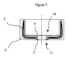
図7は、図6に表されるドーズのモールド中の圧縮から取得された多層包装体を示す。この包装体は、充填製品と接触する前記包装体の壁の表面10上には全く存在しない薄い機能層3を有する。機能層3は、前記包装体の周縁に近接して折り曲げ部を形成し、前記折り曲げ部と前記端部4は包装体の壁中に全体的に封入されている。機能層3の端部5は、包装体の外部表面11の同じ高さに存在し、前記外部表面11は充填製品と接触しないようになっている。層3は、包装体の極めて小さな表面部分にのみ存在し、この表面は、前記層3の厚みが小さいことを配慮して、全表面積のほぼ1%未満、かつ好ましくは全表面積の0.1%未満を表している。
FIG. 7 shows a multi-layer package obtained from compression in the mold of the dose represented in FIG. This package has a thin
本発明の第一もしくは第二の実施形態に対応する多くの多層ドーズを、事例によって説明する。 A number of multilayer doses corresponding to the first or second embodiment of the present invention will be described by way of example.
本発明の第一の実施形態に対応するドーズの事例は、図8に図示される。このドーズは、ドーズを形成する樹脂2中に封入される薄い機能層3を具備する。機能層は、両側面と自身の端部4と5に関して封入され、その結果機能層3はドーズの表面に全く存在しない。ドーズは、対称軸上で心出しされた穴8を含む。
An example of a dose corresponding to the first embodiment of the present invention is illustrated in FIG. This dose comprises a thin
図9は、図8に図示されたドーズのモールド中の圧縮により取得された管の肩部を示す。薄い層3は、前記肩部の内表面10と外表面11に全く存在せず、層3は肩部の周縁に折り曲げ部を形成していて、また前記層3の端部4と5は前記物体の穴9に隣接していると分る。
FIG. 9 shows the shoulder of the tube obtained by compression in the dose mold illustrated in FIG. The
図10は、穴を含み、かつ本発明の第二の実施形態に従って実現されたドーズを図示する。このドーズ1は、樹脂2に封入された機能性樹脂3の薄い層により構成される。機能性樹脂3の薄い層は、二つの自由端部4と5を含み、第一の端部4は樹脂2に全体的に封入されていて、第二の端部5は前記ドーズの表面上に存在している。
FIG. 10 illustrates a dose including a hole and realized in accordance with a second embodiment of the present invention. This
図11は、図10に図示されたドーズのモールド中の圧縮により取得された管の肩部を示す。薄い層3は、肩部の表面10に全く存在せず、前記表面10は管の内部に配置されていて、かつ充填製品と接触していると分る。層3は、肩部の周縁に折り曲げ部を形成し、かつ管の壁の内部に全体的に封入される。層3の端部5は、外部表面11上に存在し、表面11は包装体の外部側面になっている。
FIG. 11 shows the shoulder of the tube obtained by compression in the dose mold illustrated in FIG. It can be seen that there is no
図12は、多層物体を実現するために特に有利であるドーズの別の事例を示す。樹脂2の内部の薄い機能層3の端部4と5の封入は、表面上に前記層が全く存在しない物体が取得されることを可能にする。これらのドーズは、穴の有無にかかわらず多層物体を実現するために特に有利である。
FIG. 12 shows another example of a dose that is particularly advantageous for realizing a multilayer object. Encapsulation of the
図13は、自身の中心に穴を有するドーズ形状を図示する。この多層ドーズは、前記ドーズの少なくとも80%を有する第一の樹脂2中に封入される薄い機能層3を具備する。層3の端部4は、前記ドーズの圧縮中に前記層3の端部4が物体の表面に存在しないようにドーズの表面から距離6に配置される。
FIG. 13 illustrates a dose shape with a hole in its center. This multilayer dose comprises a thin
図14は、第一の樹脂2中に少なくとも一部封入される薄い機能層3を具備していて、前記樹脂2はドーズの容積の少なくとも80%を表している多層ドーズ1を示す。層3は、前記ドーズの対称軸上で心出しされた回転体のシェルを形成する。本発明の第一の実施形態に従うと、層3の端部4と5は同様に、第一の樹脂2中に封入され、その結果層3は樹脂2中に全体的に封入される。本発明の第二の実施形態に従うと、層3の端部5のみが、樹脂2中に封入されず、その結果モールド中のドーズの圧縮後、層3の端部5のみが成型された物体の表面上に配置される。
FIG. 14 shows a
図15は、前記ドーズの対称軸上で心出しされ、かつ第一の樹脂2中に少なくとも一部封入される二つの薄い機能層3′と3″を具備するドーズの別の事例を図示する。本発明の第一の実施形態に従うと、層3は、自身の端部4′と4″及び5′と5″の同じ高さにおいてさえ樹脂2中に全体的に封入される。本発明の第二の実施形態に従うと、層3′と3″の端部5′と5″のみが樹脂2中に封入されない。
FIG. 15 illustrates another example of a dose comprising two thin
図9と11に表される物体は、ポリウレタン(PE)製樹脂中に封入される防壁樹脂(EVOH)の薄い層を用いて実現された。これらの物体は、酸素もしくは香りに対し大きな不透過性を有する。 The object represented in FIGS. 9 and 11 was realized using a thin layer of barrier resin (EVOH) encapsulated in polyurethane (PE) resin. These objects are highly impermeable to oxygen or scent.
本発明の説明を平易にするために、図を意図的に、第二の樹脂2中に封入される機能層の一つのみを用いて表した。二つの樹脂のみの結合は一般に、充分な接着が二つの樹脂間の境界で達成されることを可能にしないことは周知である。異なる性質の樹脂が結合されることを可能にすると同時に、層間の接着の優れた水準を保証する、接着性中間層を使用することも常習的である。従って、防壁層の両側面上に接着性層を挿入することは、多層物体中の剥離もしくは分離の潜在的な問題を予防する。接着性と防壁性の層は類似していて、また少量である。機能層3を形成する接着層の集合体は、ドーズを形成する全樹脂量のほぼ15%未満の樹脂量、また好ましくは10%未満の量を表す。本発明は従って、図4と、6と、8と、10と、12と、13と、14に提案されるような三層ドーズに限定されるのではなく、5層以上を含むのがより一般的である。
In order to simplify the description of the present invention, the figure is intentionally represented using only one of the functional layers enclosed in the
本発明の要旨の範囲内で使用される樹脂は、現在使用されている熱可塑性樹脂、また具体的には包装業界において使用される樹脂に対応する。機能層3を形成するために使用される防壁樹脂のうちで、エチレン・ビニル・アルコール(EVOH)共ポリマと、ナイロン-MXD6などのポリアミドと、アクリルニトリル-メチル・アクリレート共ポリマ(BAREX)と、PVDFなどのフッソ化ポリマを列挙できる。これに関連して、物体の構造2を形成するために使用される数種の樹脂、ポリエチレン(PE)と、ポリプロピレン(PP)と、ポリスチレン(PS)と、ポリアミド(PA)と、ポリエステル(PET)も列挙できる。このリストは網羅的でない。樹脂の選定においては、近似する粘度を有する製品を選定することが重要である。一般的に、操作温度で、10未満の粘度比を有する樹脂を使用するのが好適であり、また3未満の粘度比が選定されるのが好ましい。
The resins used within the scope of the present invention correspond to the thermoplastic resins currently used, and specifically to the resins used in the packaging industry. Among the barrier resins used to form the
圧縮成型法は、溶融状態の合成樹脂の多層ドーズをモールドの空洞内に供給する工程と、前記モールドの空洞中の前記ドーズの圧縮成型により物体を形成する工程と、物体を冷却する工程と、次にそれをモールドから取除く工程から成る。 The compression molding method includes a step of supplying a multilayer dose of a synthetic resin in a molten state into a cavity of a mold, a step of forming an object by compression molding of the dose in the cavity of the mold, a step of cooling the object, Next, it consists of removing it from the mold.
本発明は、機能層3が物体の容積の5%未満を表示できる、極めて薄い機能層を有する物体の実現を可能にする。
The invention makes it possible to realize an object with a very thin functional layer, in which the
下記に提示される多層物体を実現するための方法は、プラグ、もしくはふた、もしくはプリフォーム、もしくは現実には管の肩部などの物体を実現するために特に有利である。この方法を、スラブの形のプリフォームを実現するために使用できることも有利であり、これらのスラブは次に、多層物体を形成するために熱成形もしくは吹き込み熱成形に使用される。 The method for realizing the multilayer object presented below is particularly advantageous for realizing objects such as plugs, lids, or preforms, or in reality the shoulders of the tubes. It is also advantageous that this method can be used to realize preforms in the form of slabs, which are then used in thermoforming or blown thermoforming to form multilayer objects.
以前に提案されたドーズを、いくつかの方法に従って実現できる。 The previously proposed dose can be achieved according to several methods.
第一の方法は、多層構造体を形成し、また少なくとも機能層3が間欠的に押出されるように、樹脂を共押出しする工程から成る。
The first method comprises a step of co-extrusion of a resin so that a multilayer structure is formed and at least the
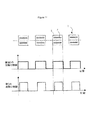
この方法の事例は、図16に図示される。多層ロッドは連続的に共押出しされ、機能層3の流動は周期的かつ間欠的になっていて、層3の周期性と前記ロッドの切断の周期性は同一になっている。この方法は、多層ドーズの高速実現に特に有利である。この方法は、樹脂2に全体的に封入される機能層3を有するドーズの実現に使用されると有利である。
An example of this method is illustrated in FIG. The multilayer rod is continuously co-extruded, the flow of the
この第一の方法に記載された多層ドーズ実現の第二の事例は、図17に図示される。多層ロッドは、間欠的に共押出しされ、その結果共押出しされた樹脂2の全体流動は、最大値とゼロ値との間を変動し、周期中にドーズされる材料の分量は、一つのドーズに対応している。機能層3は、樹脂2よりも短時間で供給され、その結果層3の端部は樹脂2中に封入される。
A second example of a multi-layer dose implementation described in this first method is illustrated in FIG. The multi-layer rod is intermittently co-extruded so that the overall flow of the
本発明に記載の多層ドーズを作製するための第二の方法は、層3の少なくとも一つの端部を樹脂2中に封入する工程から成り、前記封入は、押出しダイスの外側で実現されるようになっている。
A second method for producing a multilayer dose according to the present invention comprises the step of encapsulating at least one end of
この第二の方法の事例は、図18に図示される。カッタ9は、多層流動体が押出しダイス8を離れるとき、多層流動体を周期的に切断し、その結果ドーズ1を形成している。ドーズ1は、前記層3の端部5の同じ高さは別にして樹脂2中に封入される機能層3を含む。前記層3の端部4は樹脂2中に封入され、封入は、カッタ9による多層ロッドの切断中に実現される。前記カッタの切断移動と併用されるカッタ9の関連部分の構造は、次に層3の端部4の封入をする樹脂2の一部を引きずっている。
An example of this second method is illustrated in FIG. The
第二の方法に記載の、多層ドーズ実現の別の事例は、図19に図示される。ドーズは、管状の多層流動体から形成される。押出しダイス8から出てくる途中、カッタ9は周期的にドーズ1を切断し、かつ機能層3の端部4を樹脂2中に共同して封入する。
Another example of a multi-layer dose implementation described in the second method is illustrated in FIG. The dose is formed from a tubular multilayer fluid. On the way out of the extrusion die 8, the
類似の方法が、層3の一端部もしくは両端部を樹脂2中に封入するために使用される。これらの方法を、ドーズの切断中、もしくはモールドの空洞内への移送中、もしくは成型装置の内部への移送中に適用できる。これらの方法は、樹脂2を引きずりかつ層3の端部を封入するように、ドーズの最初の形状を改良する工程から成る共通要素を有する。
A similar method is used to encapsulate one or both ends of the
本明細書に提案される事例において、ドーズと物体は単純な形状から成るが、本発明はいずれの形状のドーズと物体にも関連するのは明らかである。 In the case proposed here, the dose and object consist of simple shapes, but it is clear that the present invention relates to any shape of dose and object.
本発明に従って取得された物体は、物体の周縁の同じ高さに少なくとも一つの折り曲げ部を形成する機能層3を含む。物体の対称軸に近接する第二の折り曲げ部を含む物体も、取得できる。機能層のジグザグ配列が、物体中に取得可能である。
The object obtained according to the invention includes a
ドーズ中の機能層3の多くの配列が可能である。前記機能層3が対称軸上で心出しされた回転体のシェルを形成するように、機能層3をドーズ中に配置することが有利である。対称軸に対する機能層3の距離が可変であるとき、有利な多層物体を取得できる。
Many arrangements of the
複数の機能層3を具備していて、前記機能層3は全て前記ドーズの対称軸上で心出しされているドーズが同様に使用される。取得された多層物体は、機能層の少なくとも一部が他方の頂部に置かれ、また各々が少なくとも一つの折り曲げ部を形成することを特徴とする。
A plurality of
他のドーズ形状が使用される。表面の一部が凹面を有するドーズが特に有利であることが観測された。そのようなドーズ形状は、多層物体中の機能層の優れた配分を容易にする。 Other dose shapes are used. It has been observed that doses with a concave part of the surface are particularly advantageous. Such a dose shape facilitates excellent distribution of the functional layers in the multilayer object.
Claims (13)
前記ドーズは、対称軸を有し、かつ第一の合成樹脂(2)と、前記対称軸の周囲に形成される回転体の外部シェルを形成する少なくとも一つの合成樹脂の薄い機能層(3)を具備し、前記回転体は、対称軸に平行な方向に配置される二つの端部を具備するものにおいて、
前記機能層(3)は、前記第一の合成樹脂(2)中に全体的に、もしくは前記端部の一つ以上が前記第一の樹脂(2)中に封入されないように、封入されることを特徴とする、
多層合成樹脂のドーズ。 A dose of multilayer synthetic resin for realizing a multilayer object by compression molding,
The dose has a symmetry axis and a thin functional layer (3) of the first synthetic resin (2) and at least one synthetic resin forming an outer shell of a rotating body formed around the symmetry axis. And the rotating body has two ends arranged in a direction parallel to the axis of symmetry,
The functional layer (3) is encapsulated in the first synthetic resin (2) entirely or in such a manner that one or more of the end portions are not encapsulated in the first resin (2). It is characterized by
Multi-layer synthetic resin dose.
前記物体は内面と外面を含み、前記物体は前記第一の合成樹脂(2)と前記薄い機能層(3)から形成され、前記機能層(3)は前記物体の壁中に封入され、かつ折り曲げ部を形成するものにおいて、
前記機能層(3)は、前記内面上に全く存在しないことを特徴とする、
多層物体。 A multilayer object obtained by compression molding from the dose according to any one of claims 1-6,
The object includes an inner surface and an outer surface, the object is formed from the first synthetic resin (2) and the thin functional layer (3), the functional layer (3) is enclosed in a wall of the object; and In what forms a bent part,
The functional layer (3) is not present at all on the inner surface,
Multilayer object.
前記樹脂は多層流動体を形成するように共押出しされ、前記流動体は個々の部分を形成するように周期的に切断され、前記部分は圧縮モールド内に移送される方法において、
前記部分は、前記第一の合成樹脂(2)を用いて前記機能層(3)の最小限一つの端部を全体的に覆うように変形されることを特徴とする、
作製方法。 A method for producing a dose according to any one of claims 1-6,
Wherein the resin is coextruded to form a multilayer fluid, the fluid is periodically cut to form individual portions, and the portions are transferred into a compression mold;
The portion is deformed so as to entirely cover at least one end of the functional layer (3) using the first synthetic resin (2).
Manufacturing method.
前記樹脂を同一方向に共押出しする工程を含む方法において、
前記機能層(3)の少なくとも一つの端部を全体的に覆うように、前記第一の樹脂(2)を単独で押出す被覆工程を、方法が含むことを特徴とする、
作製方法。 A method for producing a dose according to any one of claims 1-6,
In the method comprising the step of co-extruding the resin in the same direction,
The method includes a coating step of extruding the first resin (2) alone so as to entirely cover at least one end of the functional layer (3).
Manufacturing method.
Applications Claiming Priority (9)
| Application Number | Priority Date | Filing Date | Title |
|---|---|---|---|
| CH00336/04 | 2004-03-01 | ||
| CH3362004 | 2004-03-01 | ||
| CH01619/04 | 2004-10-04 | ||
| CH16192004 | 2004-10-04 | ||
| CH20342004 | 2004-12-08 | ||
| CH20332004 | 2004-12-08 | ||
| CH02033/04 | 2004-12-08 | ||
| CH02034/04 | 2004-12-08 | ||
| PCT/IB2005/050708 WO2005084904A1 (en) | 2004-03-01 | 2005-02-26 | Multilayer dose |
Publications (2)
| Publication Number | Publication Date |
|---|---|
| JP2007525350A true JP2007525350A (en) | 2007-09-06 |
| JP2007525350A6 JP2007525350A6 (en) | 2007-12-06 |
Family
ID=34923298
Family Applications (5)
| Application Number | Title | Priority Date | Filing Date |
|---|---|---|---|
| JP2007501418A Active JP4782768B2 (en) | 2004-03-01 | 2005-02-26 | Multilayer structure |
| JP2007501419A Expired - Fee Related JP4865696B2 (en) | 2004-03-01 | 2005-02-26 | Multi-layer material unit |
| JP2007501421A Pending JP2007525349A (en) | 2004-03-01 | 2005-02-26 | Multi-layer dose with concave surface |
| JP2007501422A Pending JP2007525350A (en) | 2004-03-01 | 2005-02-26 | Multilayer dose |
| JP2007501420A Pending JP2007525348A (en) | 2004-03-01 | 2005-02-26 | Multilayer composite object |
Family Applications Before (3)
| Application Number | Title | Priority Date | Filing Date |
|---|---|---|---|
| JP2007501418A Active JP4782768B2 (en) | 2004-03-01 | 2005-02-26 | Multilayer structure |
| JP2007501419A Expired - Fee Related JP4865696B2 (en) | 2004-03-01 | 2005-02-26 | Multi-layer material unit |
| JP2007501421A Pending JP2007525349A (en) | 2004-03-01 | 2005-02-26 | Multi-layer dose with concave surface |
Family Applications After (1)
| Application Number | Title | Priority Date | Filing Date |
|---|---|---|---|
| JP2007501420A Pending JP2007525348A (en) | 2004-03-01 | 2005-02-26 | Multilayer composite object |
Country Status (15)
| Country | Link |
|---|---|
| US (5) | US7959996B2 (en) |
| EP (5) | EP1720690B1 (en) |
| JP (5) | JP4782768B2 (en) |
| KR (4) | KR101154849B1 (en) |
| CN (5) | CN1925961B (en) |
| AT (1) | ATE478013T1 (en) |
| BR (5) | BRPI0508344A (en) |
| CA (5) | CA2557584C (en) |
| DE (1) | DE602005022983D1 (en) |
| ES (2) | ES2451666T3 (en) |
| HK (4) | HK1096907A1 (en) |
| PL (1) | PL1720770T3 (en) |
| RU (5) | RU2352459C2 (en) |
| SI (2) | SI1720770T1 (en) |
| WO (5) | WO2005084904A1 (en) |
Families Citing this family (13)
| Publication number | Priority date | Publication date | Assignee | Title |
|---|---|---|---|---|
| EP1832414A1 (en) * | 2006-03-10 | 2007-09-12 | Aisapack Holding SA | Synthetic multilayer object |
| EP1955835A1 (en) * | 2007-02-07 | 2008-08-13 | Aisapack Holding SA | Method of manufacturing a multi-layered object |
| ATE545492T1 (en) * | 2007-09-05 | 2012-03-15 | Aisapack Holding Sa | MULTI-LAYER OBJECT WITH VARIABLE THICKNESS |
| AU2009311786B2 (en) * | 2008-11-05 | 2013-10-17 | Colin Gilbert Tobeck And Rosalie Bernadette Tobeck As Trustees Of The Progressive Endeavours Trust | A fluid receiver |
| US10464280B2 (en) | 2011-08-30 | 2019-11-05 | Shanghai Yanfeng Jinqiao Automotive Trim Systems Co. Ltd. | Trim component for vehicle interior |
| CN107263799B (en) | 2011-08-30 | 2019-12-03 | 上海延锋金桥汽车饰件系统有限公司 | A kind of method manufacturing automobile interior component in a mold and the gadget for vehicle interior |
| DE102012103067A1 (en) | 2012-04-10 | 2013-10-10 | Packsys Global (Switzerland) Ltd. | Packaging tube has metal layer-free insert element, which is assigned to tube head for improving barrier properties in area of tube head, where insert element is formed as thermoform element |
| US10093268B2 (en) | 2012-08-27 | 2018-10-09 | Shanghai Yanfeng Jinqiao Automotive Trim Systems Co. Ltd. | Trim component for vehicle interior |
| US9221204B2 (en) * | 2013-03-14 | 2015-12-29 | Kortec, Inc. | Techniques to mold parts with injection-formed aperture in gate area |
| CN105128303B (en) | 2015-09-30 | 2016-06-22 | 东莞市金富实业有限公司 | A kind of illusion-colour bottle cap compacting assembly |
| JP2017159927A (en) * | 2016-03-08 | 2017-09-14 | 凸版印刷株式会社 | Laminate tube |
| CN106005710A (en) * | 2016-06-30 | 2016-10-12 | 中国农业大学 | High-performance barrier film packaging bag and method for packaging and storing new-made steam-flaked grains |
| WO2020006290A1 (en) | 2018-06-28 | 2020-01-02 | Shanghai Yanfeng Jinqiao Automotive Trim Systems Co. Ltd. | Vehicle trim component |
Citations (6)
| Publication number | Priority date | Publication date | Assignee | Title |
|---|---|---|---|---|
| US4154893A (en) * | 1972-09-15 | 1979-05-15 | Conrad Goldman | Production of thermoplastic billets and preforms |
| JPS62184817A (en) * | 1986-02-10 | 1987-08-13 | Toyo Seikan Kaisha Ltd | Compression molded product with multi-layer construction and manufacture and device thereof |
| JPH0298415A (en) * | 1988-10-06 | 1990-04-10 | Ueno Hiroshi | Manufacture of compression molding having multilayer structure |
| JPH02134222A (en) * | 1988-11-15 | 1990-05-23 | Ueno Hiroshi | Compression molding method |
| JPH11268782A (en) * | 1998-01-21 | 1999-10-05 | Ueno Hiroshi | Container nozzle integrated in body via connection part, nozzle-having pushout container, and production thereof |
| JP2003039531A (en) * | 2001-05-23 | 2003-02-13 | Toyo Seikan Kaisha Ltd | Multi-layer preform and multi-layer bottle using the same |
Family Cites Families (40)
| Publication number | Priority date | Publication date | Assignee | Title |
|---|---|---|---|---|
| US3295725A (en) * | 1962-12-07 | 1967-01-03 | American Can Co | Collapsible dispensing container with an impermeable barrier both in its laminated wall and in its headpiece |
| GB1074683A (en) | 1962-11-13 | 1967-07-05 | American Can Co | Collapsible container structure and method of making same |
| FR1466947A (en) * | 1966-02-03 | 1967-01-20 | Dow Chemical Co | Method of manufacturing a composite article made of thermoplastic materials and apparatus for its implementation |
| US3969563A (en) * | 1969-08-28 | 1976-07-13 | Hollis Sr Russell E | Protective wall structure |
| FR2180831B3 (en) | 1972-04-17 | 1976-04-02 | Usm Corp | |
| JPS5325855B2 (en) * | 1972-06-07 | 1978-07-29 | ||
| JPS51100163A (en) * | 1975-02-28 | 1976-09-03 | Ishikawajima Harima Heavy Ind | Tasotojotaino oshidashiseikeisochi |
| FR2299957B1 (en) | 1975-02-28 | 1978-12-08 | Ishikawajima Harima Heavy Ind | BLOW MOLDING PROCESS AND MACHINE |
| JPS5495678A (en) * | 1978-01-12 | 1979-07-28 | Toppan Printing Co Ltd | Extruded tube container |
| US4419412A (en) * | 1980-12-16 | 1983-12-06 | Ball Corporation | Plastic blank structure |
| US4390487A (en) * | 1982-01-26 | 1983-06-28 | Rca Corporation | Method of making a laminated recorded disc |
| US5523045A (en) * | 1983-04-13 | 1996-06-04 | American National Can Company | Methods for injection molding and blow-molding multi-layer plastic articles |
| JPS60258425A (en) | 1984-05-25 | 1985-12-20 | Honda Motor Co Ltd | Remelting and hardening method of cam shaft |
| JPS60259425A (en) | 1984-06-05 | 1985-12-21 | Ikegai Corp | Multilayer continuous molding method and device thereof |
| JPS61259942A (en) * | 1985-05-10 | 1986-11-18 | 東洋製罐株式会社 | Draw-formed multilayer vessel and blank used for said vessel |
| DE3518441A1 (en) * | 1985-05-22 | 1986-11-27 | Krupp Corpoplast Maschinenbau GmbH, 2000 Hamburg | METHOD FOR PRODUCING A MOLD FOR BLOW MOLDING A HOLLOW BODY |
| DE3545162A1 (en) * | 1985-12-20 | 1987-07-02 | Battenfeld Fischer Blasform | METHOD AND DEVICE FOR PRODUCING HOLLOW BODIES FROM THERMOPLASTIC PLASTICS |
| JPS6319208A (en) * | 1986-07-11 | 1988-01-27 | Dainippon Printing Co Ltd | Premolded product |
| US4940557A (en) * | 1987-12-28 | 1990-07-10 | Hashmoto Forming Industry Co., Ltd. | Method of manufacturing molding members |
| JPH0649318B2 (en) * | 1988-01-30 | 1994-06-29 | 東洋製罐株式会社 | Nozzle device for composite synthetic resin extrusion |
| US4921647A (en) * | 1988-10-27 | 1990-05-01 | Shell Oil Company | Method of shaping a laminated thermoplastic billet |
| DE3922883A1 (en) * | 1989-07-12 | 1991-01-24 | Kautex Maschinenbau Gmbh | METHOD AND DEVICE FOR PRODUCING HOLLOW BODIES FROM THERMOPLASTIC PLASTIC |
| JPH03254919A (en) | 1990-03-06 | 1991-11-13 | Takata Kk | Manufacture of module cover of air bag |
| US5128084A (en) | 1990-07-24 | 1992-07-07 | Bridgestone Firestone Inc | Coextrusion apparatus and method for varying the inner profile of a tubular extrudate |
| WO1993005985A1 (en) * | 1991-09-27 | 1993-04-01 | Teijin Limited | Airtight woven sheet for air bags and method of manufacturing the same |
| JP2500724B2 (en) * | 1992-04-06 | 1996-05-29 | 東洋製罐株式会社 | Method and apparatus for forming composite synthetic resin material |
| DE4404970C1 (en) * | 1994-02-17 | 1995-02-23 | Tubex Gmbh | Plastics tube and process for producing a plastics tube |
| JP3839135B2 (en) | 1997-06-13 | 2006-11-01 | 株式会社プライムポリマー | Resin molded body, method for manufacturing the same, and manufacturing apparatus therefor |
| CN1102094C (en) * | 1997-10-02 | 2003-02-26 | 博雷里斯有限公司 | Differentiated pressing process |
| US20020109267A1 (en) | 1997-10-02 | 2002-08-15 | Harald Herbst | Differentiated press-molding process |
| DE19814314B4 (en) * | 1998-03-31 | 2016-07-28 | Volkswagen Ag | Process for the production of hollow bodies made of thermoplastic material and hollow body produced by this process |
| JP2000326393A (en) * | 1999-05-18 | 2000-11-28 | Showa Denko Kk | Multilayer bottle, its preform and their manufacture |
| JP4727016B2 (en) | 1999-09-30 | 2011-07-20 | 株式会社クラレ | Fuel container with excellent gasoline barrier properties |
| JP4270687B2 (en) * | 1999-11-16 | 2009-06-03 | 大日本印刷株式会社 | Manufacturing method of tube containers |
| US6613408B1 (en) * | 1999-12-18 | 2003-09-02 | Delphi Technologies, Inc. | Fuel permeation barrier fuel tank |
| US6467643B1 (en) * | 2000-02-25 | 2002-10-22 | Salflex Polymers Ltd. | Sealing bead |
| FI111057B (en) | 2000-05-29 | 2003-05-30 | Conenor Oy | Extrusion procedure and extruder |
| FR2813818B1 (en) * | 2000-09-14 | 2003-05-30 | Solvay Automotive Fuel Systems | MULTILAYER HOLLOW BODY, PROCESS FOR MANUFACTURING SUCH HOLLOW BODY AND COMPRESSION-BLOW MOLD |
| IT1316150B1 (en) | 2000-11-28 | 2003-03-28 | Intercable Srl | INJECTION MELTING PROCEDURE FOR THE MANUFACTURE OF CAPS OR SIMILAR VENTS, SIZE THICK. |
| JP3896524B2 (en) * | 2000-12-20 | 2007-03-22 | 株式会社吉野工業所 | Synthetic resin biaxial stretch blow molding |
-
2005
- 2005-02-26 BR BRPI0508344-3A patent/BRPI0508344A/en not_active IP Right Cessation
- 2005-02-26 EP EP20050708853 patent/EP1720690B1/en active Active
- 2005-02-26 KR KR1020067019420A patent/KR101154849B1/en active IP Right Grant
- 2005-02-26 SI SI200531158T patent/SI1720770T1/en unknown
- 2005-02-26 WO PCT/IB2005/050708 patent/WO2005084904A1/en active Application Filing
- 2005-02-26 RU RU2006133974/12A patent/RU2352459C2/en not_active IP Right Cessation
- 2005-02-26 ES ES05708853T patent/ES2451666T3/en active Active
- 2005-02-26 WO PCT/IB2005/050706 patent/WO2005084902A1/en active Application Filing
- 2005-02-26 US US10/591,117 patent/US7959996B2/en active Active
- 2005-02-26 CN CN200580006727XA patent/CN1925961B/en not_active Expired - Fee Related
- 2005-02-26 RU RU2006133975/12A patent/RU2359824C2/en not_active IP Right Cessation
- 2005-02-26 AT AT05708852T patent/ATE478013T1/en active
- 2005-02-26 RU RU2006133972/12A patent/RU2354552C2/en not_active IP Right Cessation
- 2005-02-26 DE DE200560022983 patent/DE602005022983D1/en active Active
- 2005-02-26 RU RU2006133721/12A patent/RU2358889C2/en not_active IP Right Cessation
- 2005-02-26 CA CA 2557584 patent/CA2557584C/en active Active
- 2005-02-26 CN CNA2005800067246A patent/CN1925959A/en active Pending
- 2005-02-26 CN CN2005800067265A patent/CN1926027B/en not_active Expired - Fee Related
- 2005-02-26 CA CA 2557590 patent/CA2557590C/en not_active Expired - Fee Related
- 2005-02-26 ES ES05708852T patent/ES2350188T3/en active Active
- 2005-02-26 US US10/591,116 patent/US20070184236A1/en not_active Abandoned
- 2005-02-26 EP EP05708854A patent/EP1720691A1/en not_active Withdrawn
- 2005-02-26 PL PL05708852T patent/PL1720770T3/en unknown
- 2005-02-26 KR KR1020067018941A patent/KR20070003942A/en not_active Application Discontinuation
- 2005-02-26 JP JP2007501418A patent/JP4782768B2/en active Active
- 2005-02-26 WO PCT/IB2005/050707 patent/WO2005084903A1/en active Application Filing
- 2005-02-26 WO PCT/IB2005/050705 patent/WO2005087473A1/en active Application Filing
- 2005-02-26 BR BRPI0508323-0A patent/BRPI0508323A/en not_active IP Right Cessation
- 2005-02-26 EP EP20050708855 patent/EP1720692B1/en not_active Not-in-force
- 2005-02-26 WO PCT/IB2005/050704 patent/WO2005087601A1/en active Application Filing
- 2005-02-26 JP JP2007501419A patent/JP4865696B2/en not_active Expired - Fee Related
- 2005-02-26 CA CA 2557616 patent/CA2557616A1/en not_active Abandoned
- 2005-02-26 CN CN2005800067284A patent/CN1925962B/en not_active Expired - Fee Related
- 2005-02-26 BR BRPI0508331A patent/BRPI0508331B1/en not_active IP Right Cessation
- 2005-02-26 CN CN2005800067250A patent/CN1925960B/en not_active Expired - Fee Related
- 2005-02-26 EP EP05708856.9A patent/EP1727657B1/en active Active
- 2005-02-26 RU RU2006133722/12A patent/RU2006133722A/en not_active Application Discontinuation
- 2005-02-26 CA CA 2557622 patent/CA2557622A1/en not_active Abandoned
- 2005-02-26 SI SI200531832T patent/SI1720690T1/en unknown
- 2005-02-26 CA CA 2557627 patent/CA2557627C/en not_active Expired - Fee Related
- 2005-02-26 US US10/591,126 patent/US7923085B2/en not_active Expired - Fee Related
- 2005-02-26 JP JP2007501421A patent/JP2007525349A/en active Pending
- 2005-02-26 JP JP2007501422A patent/JP2007525350A/en active Pending
- 2005-02-26 BR BRPI0508338A patent/BRPI0508338B1/en not_active IP Right Cessation
- 2005-02-26 EP EP20050708852 patent/EP1720770B1/en active Active
- 2005-02-26 KR KR1020067019358A patent/KR101149790B1/en not_active IP Right Cessation
- 2005-02-26 US US10/590,201 patent/US7875330B2/en active Active
- 2005-02-26 BR BRPI0508336A patent/BRPI0508336B1/en not_active IP Right Cessation
- 2005-02-26 US US10/591,127 patent/US7968162B2/en active Active
- 2005-02-26 JP JP2007501420A patent/JP2007525348A/en active Pending
-
2006
- 2006-09-11 KR KR1020067018508A patent/KR101080854B1/en active IP Right Grant
-
2007
- 2007-05-02 HK HK07104654A patent/HK1096907A1/en not_active IP Right Cessation
- 2007-05-14 HK HK07105051A patent/HK1097486A1/en not_active IP Right Cessation
- 2007-05-14 HK HK07105050A patent/HK1097802A1/en not_active IP Right Cessation
- 2007-05-14 HK HK07105049A patent/HK1097497A1/en not_active IP Right Cessation
Patent Citations (6)
| Publication number | Priority date | Publication date | Assignee | Title |
|---|---|---|---|---|
| US4154893A (en) * | 1972-09-15 | 1979-05-15 | Conrad Goldman | Production of thermoplastic billets and preforms |
| JPS62184817A (en) * | 1986-02-10 | 1987-08-13 | Toyo Seikan Kaisha Ltd | Compression molded product with multi-layer construction and manufacture and device thereof |
| JPH0298415A (en) * | 1988-10-06 | 1990-04-10 | Ueno Hiroshi | Manufacture of compression molding having multilayer structure |
| JPH02134222A (en) * | 1988-11-15 | 1990-05-23 | Ueno Hiroshi | Compression molding method |
| JPH11268782A (en) * | 1998-01-21 | 1999-10-05 | Ueno Hiroshi | Container nozzle integrated in body via connection part, nozzle-having pushout container, and production thereof |
| JP2003039531A (en) * | 2001-05-23 | 2003-02-13 | Toyo Seikan Kaisha Ltd | Multi-layer preform and multi-layer bottle using the same |
Also Published As
Similar Documents
| Publication | Publication Date | Title |
|---|---|---|
| JP2007525350A6 (en) | Multilayer dose | |
| JP2007525350A (en) | Multilayer dose | |
| JP2007525348A6 (en) | Multilayer composite object | |
| JP2007525349A6 (en) | Multi-layer dose with concave surface | |
| JP2007527806A6 (en) | Multilayer structure | |
| JP2007527806A5 (en) | ||
| JP2007525347A6 (en) | Multilayer dose | |
| JP2007525347A5 (en) | ||
| CN107848185B (en) | Stopping pipe shoulder | |
| JP5992294B2 (en) | Blow molding container | |
| ES2336367T3 (en) | MUTICAPA OBJECTS AND PROCEDURE OF REALIZATION. | |
| JP5985357B2 (en) | Blow molding container | |
| MXPA06010025A (en) | Multilayer dose | |
| JPS6055285B2 (en) | Method for manufacturing tube containers | |
| JP3556344B2 (en) | Laminated blow container | |
| WO2004062881A1 (en) | Container having a double wall structure, manufacturing method and apparatus therefor | |
| JP4171903B2 (en) | Multi-layer resin lump | |
| KR101173742B1 (en) | Disposable sanitary bag with embossing surfaces | |
| KR20070017137A (en) | Multilayer does having a concave surface | |
| MXPA06010027A (en) | Synthetic multilayer object | |
| MXPA06009911A (en) | Multilayer dose | |
| MXPA06009910A (en) | Multilayer dose having a concave surface |
Legal Events
| Date | Code | Title | Description |
|---|---|---|---|
| A621 | Written request for application examination |
Free format text: JAPANESE INTERMEDIATE CODE: A621 Effective date: 20080109 |
|
| A977 | Report on retrieval |
Free format text: JAPANESE INTERMEDIATE CODE: A971007 Effective date: 20101209 |
|
| A131 | Notification of reasons for refusal |
Free format text: JAPANESE INTERMEDIATE CODE: A131 Effective date: 20101214 |
|
| A601 | Written request for extension of time |
Free format text: JAPANESE INTERMEDIATE CODE: A601 Effective date: 20110314 |
|
| A602 | Written permission of extension of time |
Free format text: JAPANESE INTERMEDIATE CODE: A602 Effective date: 20110322 |
|
| A521 | Request for written amendment filed |
Free format text: JAPANESE INTERMEDIATE CODE: A523 Effective date: 20110406 |
|
| A131 | Notification of reasons for refusal |
Free format text: JAPANESE INTERMEDIATE CODE: A131 Effective date: 20110712 |
|
| A601 | Written request for extension of time |
Free format text: JAPANESE INTERMEDIATE CODE: A601 Effective date: 20111011 |
|
| A602 | Written permission of extension of time |
Free format text: JAPANESE INTERMEDIATE CODE: A602 Effective date: 20111018 |
|
| A02 | Decision of refusal |
Free format text: JAPANESE INTERMEDIATE CODE: A02 Effective date: 20120306 |