EP1832414A1 - Synthetic multilayer object - Google Patents
Synthetic multilayer object Download PDFInfo
- Publication number
- EP1832414A1 EP1832414A1 EP06110994A EP06110994A EP1832414A1 EP 1832414 A1 EP1832414 A1 EP 1832414A1 EP 06110994 A EP06110994 A EP 06110994A EP 06110994 A EP06110994 A EP 06110994A EP 1832414 A1 EP1832414 A1 EP 1832414A1
- Authority
- EP
- European Patent Office
- Prior art keywords
- multilayer
- dose
- axis
- symmetry
- object according
- Prior art date
- Legal status (The legal status is an assumption and is not a legal conclusion. Google has not performed a legal analysis and makes no representation as to the accuracy of the status listed.)
- Withdrawn
Links
Images


Classifications
-
- B—PERFORMING OPERATIONS; TRANSPORTING
- B65—CONVEYING; PACKING; STORING; HANDLING THIN OR FILAMENTARY MATERIAL
- B65D—CONTAINERS FOR STORAGE OR TRANSPORT OF ARTICLES OR MATERIALS, e.g. BAGS, BARRELS, BOTTLES, BOXES, CANS, CARTONS, CRATES, DRUMS, JARS, TANKS, HOPPERS, FORWARDING CONTAINERS; ACCESSORIES, CLOSURES, OR FITTINGS THEREFOR; PACKAGING ELEMENTS; PACKAGES
- B65D41/00—Caps, e.g. crown caps or crown seals, i.e. members having parts arranged for engagement with the external periphery of a neck or wall defining a pouring opening or discharge aperture; Protective cap-like covers for closure members, e.g. decorative covers of metal foil or paper
- B65D41/02—Caps or cap-like covers without lines of weakness, tearing strips, tags, or like opening or removal devices
-
- B—PERFORMING OPERATIONS; TRANSPORTING
- B29—WORKING OF PLASTICS; WORKING OF SUBSTANCES IN A PLASTIC STATE IN GENERAL
- B29B—PREPARATION OR PRETREATMENT OF THE MATERIAL TO BE SHAPED; MAKING GRANULES OR PREFORMS; RECOVERY OF PLASTICS OR OTHER CONSTITUENTS OF WASTE MATERIAL CONTAINING PLASTICS
- B29B11/00—Making preforms
- B29B11/06—Making preforms by moulding the material
- B29B11/12—Compression moulding
-
- B—PERFORMING OPERATIONS; TRANSPORTING
- B29—WORKING OF PLASTICS; WORKING OF SUBSTANCES IN A PLASTIC STATE IN GENERAL
- B29B—PREPARATION OR PRETREATMENT OF THE MATERIAL TO BE SHAPED; MAKING GRANULES OR PREFORMS; RECOVERY OF PLASTICS OR OTHER CONSTITUENTS OF WASTE MATERIAL CONTAINING PLASTICS
- B29B11/00—Making preforms
- B29B11/14—Making preforms characterised by structure or composition
-
- B—PERFORMING OPERATIONS; TRANSPORTING
- B29—WORKING OF PLASTICS; WORKING OF SUBSTANCES IN A PLASTIC STATE IN GENERAL
- B29C—SHAPING OR JOINING OF PLASTICS; SHAPING OF MATERIAL IN A PLASTIC STATE, NOT OTHERWISE PROVIDED FOR; AFTER-TREATMENT OF THE SHAPED PRODUCTS, e.g. REPAIRING
- B29C43/00—Compression moulding, i.e. applying external pressure to flow the moulding material; Apparatus therefor
- B29C43/02—Compression moulding, i.e. applying external pressure to flow the moulding material; Apparatus therefor of articles of definite length, i.e. discrete articles
- B29C43/14—Compression moulding, i.e. applying external pressure to flow the moulding material; Apparatus therefor of articles of definite length, i.e. discrete articles in several steps
- B29C43/146—Compression moulding, i.e. applying external pressure to flow the moulding material; Apparatus therefor of articles of definite length, i.e. discrete articles in several steps for making multilayered articles
-
- B—PERFORMING OPERATIONS; TRANSPORTING
- B29—WORKING OF PLASTICS; WORKING OF SUBSTANCES IN A PLASTIC STATE IN GENERAL
- B29C—SHAPING OR JOINING OF PLASTICS; SHAPING OF MATERIAL IN A PLASTIC STATE, NOT OTHERWISE PROVIDED FOR; AFTER-TREATMENT OF THE SHAPED PRODUCTS, e.g. REPAIRING
- B29C43/00—Compression moulding, i.e. applying external pressure to flow the moulding material; Apparatus therefor
- B29C43/32—Component parts, details or accessories; Auxiliary operations
- B29C43/34—Feeding the material to the mould or the compression means
-
- B—PERFORMING OPERATIONS; TRANSPORTING
- B29—WORKING OF PLASTICS; WORKING OF SUBSTANCES IN A PLASTIC STATE IN GENERAL
- B29C—SHAPING OR JOINING OF PLASTICS; SHAPING OF MATERIAL IN A PLASTIC STATE, NOT OTHERWISE PROVIDED FOR; AFTER-TREATMENT OF THE SHAPED PRODUCTS, e.g. REPAIRING
- B29C49/00—Blow-moulding, i.e. blowing a preform or parison to a desired shape within a mould; Apparatus therefor
- B29C49/071—Preforms or parisons characterised by their configuration, e.g. geometry, dimensions or physical properties
-
- B—PERFORMING OPERATIONS; TRANSPORTING
- B65—CONVEYING; PACKING; STORING; HANDLING THIN OR FILAMENTARY MATERIAL
- B65D—CONTAINERS FOR STORAGE OR TRANSPORT OF ARTICLES OR MATERIALS, e.g. BAGS, BARRELS, BOTTLES, BOXES, CANS, CARTONS, CRATES, DRUMS, JARS, TANKS, HOPPERS, FORWARDING CONTAINERS; ACCESSORIES, CLOSURES, OR FITTINGS THEREFOR; PACKAGING ELEMENTS; PACKAGES
- B65D1/00—Containers having bodies formed in one piece, e.g. by casting metallic material, by moulding plastics, by blowing vitreous material, by throwing ceramic material, by moulding pulped fibrous material, by deep-drawing operations performed on sheet material
- B65D1/02—Bottles or similar containers with necks or like restricted apertures, designed for pouring contents
- B65D1/0207—Bottles or similar containers with necks or like restricted apertures, designed for pouring contents characterised by material, e.g. composition, physical features
- B65D1/0215—Bottles or similar containers with necks or like restricted apertures, designed for pouring contents characterised by material, e.g. composition, physical features multilayered
-
- B—PERFORMING OPERATIONS; TRANSPORTING
- B29—WORKING OF PLASTICS; WORKING OF SUBSTANCES IN A PLASTIC STATE IN GENERAL
- B29C—SHAPING OR JOINING OF PLASTICS; SHAPING OF MATERIAL IN A PLASTIC STATE, NOT OTHERWISE PROVIDED FOR; AFTER-TREATMENT OF THE SHAPED PRODUCTS, e.g. REPAIRING
- B29C43/00—Compression moulding, i.e. applying external pressure to flow the moulding material; Apparatus therefor
- B29C43/32—Component parts, details or accessories; Auxiliary operations
- B29C43/34—Feeding the material to the mould or the compression means
- B29C2043/3488—Feeding the material to the mould or the compression means uniformly distributed into the mould
-
- B—PERFORMING OPERATIONS; TRANSPORTING
- B29—WORKING OF PLASTICS; WORKING OF SUBSTANCES IN A PLASTIC STATE IN GENERAL
- B29C—SHAPING OR JOINING OF PLASTICS; SHAPING OF MATERIAL IN A PLASTIC STATE, NOT OTHERWISE PROVIDED FOR; AFTER-TREATMENT OF THE SHAPED PRODUCTS, e.g. REPAIRING
- B29C43/00—Compression moulding, i.e. applying external pressure to flow the moulding material; Apparatus therefor
- B29C43/32—Component parts, details or accessories; Auxiliary operations
- B29C43/58—Measuring, controlling or regulating
- B29C2043/5833—Measuring, controlling or regulating movement of moulds or mould parts, e.g. opening or closing, actuating
- B29C2043/5841—Measuring, controlling or regulating movement of moulds or mould parts, e.g. opening or closing, actuating for accommodating variation in mould spacing or cavity volume during moulding
-
- B—PERFORMING OPERATIONS; TRANSPORTING
- B29—WORKING OF PLASTICS; WORKING OF SUBSTANCES IN A PLASTIC STATE IN GENERAL
- B29C—SHAPING OR JOINING OF PLASTICS; SHAPING OF MATERIAL IN A PLASTIC STATE, NOT OTHERWISE PROVIDED FOR; AFTER-TREATMENT OF THE SHAPED PRODUCTS, e.g. REPAIRING
- B29C2949/00—Indexing scheme relating to blow-moulding
- B29C2949/07—Preforms or parisons characterised by their configuration
- B29C2949/0715—Preforms or parisons characterised by their configuration the preform having one end closed
-
- B—PERFORMING OPERATIONS; TRANSPORTING
- B29—WORKING OF PLASTICS; WORKING OF SUBSTANCES IN A PLASTIC STATE IN GENERAL
- B29C—SHAPING OR JOINING OF PLASTICS; SHAPING OF MATERIAL IN A PLASTIC STATE, NOT OTHERWISE PROVIDED FOR; AFTER-TREATMENT OF THE SHAPED PRODUCTS, e.g. REPAIRING
- B29C43/00—Compression moulding, i.e. applying external pressure to flow the moulding material; Apparatus therefor
- B29C43/02—Compression moulding, i.e. applying external pressure to flow the moulding material; Apparatus therefor of articles of definite length, i.e. discrete articles
- B29C43/20—Making multilayered or multicoloured articles
- B29C43/203—Making multilayered articles
-
- B—PERFORMING OPERATIONS; TRANSPORTING
- B29—WORKING OF PLASTICS; WORKING OF SUBSTANCES IN A PLASTIC STATE IN GENERAL
- B29L—INDEXING SCHEME ASSOCIATED WITH SUBCLASS B29C, RELATING TO PARTICULAR ARTICLES
- B29L2009/00—Layered products
-
- B—PERFORMING OPERATIONS; TRANSPORTING
- B65—CONVEYING; PACKING; STORING; HANDLING THIN OR FILAMENTARY MATERIAL
- B65D—CONTAINERS FOR STORAGE OR TRANSPORT OF ARTICLES OR MATERIALS, e.g. BAGS, BARRELS, BOTTLES, BOXES, CANS, CARTONS, CRATES, DRUMS, JARS, TANKS, HOPPERS, FORWARDING CONTAINERS; ACCESSORIES, CLOSURES, OR FITTINGS THEREFOR; PACKAGING ELEMENTS; PACKAGES
- B65D2251/00—Details relating to container closures
- B65D2251/07—Closures specially adapted for closing bottle-necks of non-circular cross-section
-
- B—PERFORMING OPERATIONS; TRANSPORTING
- B65—CONVEYING; PACKING; STORING; HANDLING THIN OR FILAMENTARY MATERIAL
- B65D—CONTAINERS FOR STORAGE OR TRANSPORT OF ARTICLES OR MATERIALS, e.g. BAGS, BARRELS, BOTTLES, BOXES, CANS, CARTONS, CRATES, DRUMS, JARS, TANKS, HOPPERS, FORWARDING CONTAINERS; ACCESSORIES, CLOSURES, OR FITTINGS THEREFOR; PACKAGING ELEMENTS; PACKAGES
- B65D2501/00—Containers having bodies formed in one piece
- B65D2501/0009—Bottles or similar containers with necks or like restricted apertures designed for pouring contents
- B65D2501/0081—Bottles of non-circular cross-section
-
- B—PERFORMING OPERATIONS; TRANSPORTING
- B65—CONVEYING; PACKING; STORING; HANDLING THIN OR FILAMENTARY MATERIAL
- B65D—CONTAINERS FOR STORAGE OR TRANSPORT OF ARTICLES OR MATERIALS, e.g. BAGS, BARRELS, BOTTLES, BOXES, CANS, CARTONS, CRATES, DRUMS, JARS, TANKS, HOPPERS, FORWARDING CONTAINERS; ACCESSORIES, CLOSURES, OR FITTINGS THEREFOR; PACKAGING ELEMENTS; PACKAGES
- B65D2501/00—Containers having bodies formed in one piece
- B65D2501/0009—Bottles or similar containers with necks or like restricted apertures designed for pouring contents
- B65D2501/009—Necks of non-circular cross-section
Definitions
- the present invention relates to multilayer objects without axial symmetry and their method of production.
- Licences US4876052 , JP2098415 and patent applications W02005087473 , W02005087601 , W02005084904 , W02005084903 , W02005084902 describe multilayer objects as well as methods or techniques for manufacturing multilayer objects by compression molding. These methods consist in compressing in a mold a multilayer dose of thermoplastic resins in the molten state; the crushing of said dose leading to an object also having a multilayer structure.
- the objects obtained according to these methods have particularly advantageous properties resulting from the multilayer structure which is obtained in the thickness of the object. Thus, such objects may have reduced permeability to gases, flavors, or various chemical substances.
- the invention relates to multilayer objects without axis of symmetry made by compression molding a multilayer dose; as well as their method of manufacturing.
- These objects may be for example oval tube heads, oval plugs, or rectangular packaging components.
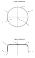
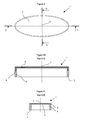
- Figures 1 and 2 illustrate a multilayer object of the prior art forming a body of revolution.
- the flow lengths are identical around the axis of symmetry.
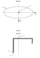
- Figures 3 and 4 illustrate a multilayer object without axis of symmetry, but having identical flow lengths around the feed center 2 of the dose.
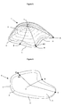
- Figure 5 illustrates the inventive concept for an object of three-dimensional geometry.
- This object without axis of symmetry comprises a central multilayer portion and at least a monolayer portion 6 located near the end 3 of the object.
- the end 4 of the multilayer structure 5 is located at a variable distance from the end 3 of the object.
- Figure 6 illustrates the inventive concept for a flat part.
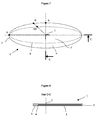
- Figures 7 and 8 show the application of the invention for a planar object of oval or elliptical geometry.
- Figures 9 to 11 illustrate a multilayer oval plug made according to the invention.
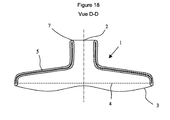
- Figures 12 to 15 illustrate a multilayer oval head of flexible tube. These figures show the modified geometry of the object so that the multilayer portion of the object is superimposed with the multilayer flexible skirt assembled by welding or overmolding.
- Figures 16 to 18 illustrate the application of the invention to multilayer square geometry heads for cardboard bricks.
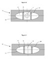
- Figures 20 to 23 illustrate a molding method of guiding the flow into the mold cavity.
- the invention relates to a multilayer object not forming a body of revolution, the object being manufactured by compression molding a multilayer dose of thermoplastic resin in the molten state.
- the prior art describes objects forming bodies of revolution. These objects are characterized in that the flow length between the axis of symmetry, which is also the center of supply of the dose, and the edge forming the periphery of the object is constant. For these objects, the radial propagation of the multilayer structure during the compression of the dose is identical in all directions. The multilayer structure thus also forms a body of revolution inside the object.
- Figure 1 illustrates a multilayer object of the prior art.
- the multilayer object 1 comprises a feed center 2 corresponding to the point around which the dose is centered in the mold before compression.
- the point 2 corresponds to the intersection between the object 1 and the axis of symmetry.
- Point 2 is also the center of flow, that is, the point around which the material flows during compression.
- the end 3 of the object corresponds to the greatest distance of flow.
- the multilayer structure has a boundary 4 from which the thickness of the object is formed of only one layer.
- the outline 4 defines the multilayer portion 5 of the monolayer portion 6 of the object.
- the distance between the contours 3 and 4 is constant.
- Figure 2 shows the sectional view of the object.
- the multilayer structure forms a portion of said object that extends from the flow center to the end 4. Since the object forms a body of revolution, the flow is identical in all directions around point 2.
- the radial propagation of the multilayer structure varies according to the directions.
- the optimization of the geometry of the object and the process can not be done from the descriptions of the prior art.
- a difficulty in producing multilayer objects by compression molding is to control the propagation of the different layers and in particular to prevent trapped layers from appearing on the surface of the object. Since the flows are not identical in all directions, the control of the position of the layers in the object can not be deduced from the descriptions of the prior art.
- Another difficulty is the optimization of the geometry and the process so that the multilayer structure extends over a large part of the object.
- FIG. 4 represents a sectional view along I-direction A of the object shown in FIG. 3. As shown in FIG. 3, this object does not form a body of revolution. However, it is possible to apply for these objects the same rules as objects forming a body of revolution, because the formation and propagation of the multilayer structure during compression mainly depends on the flow and the path traveled. In this case, the path traveled is identical in all directions from the center of compression or supply of the dose, as shown by the sectional view of the object shown in Figure 4. The distance between the feeding center G and the end 3 is constant.
- An object without an axis of symmetry is compression molded with a multilayer resin dose.
- This object shown in FIG. 5 forms a shell delimited by an edge 3.
- There is not in this object a point of the shell from which the curvilinear length connecting the edge 3 is constant.
- This object has a point 2 corresponding to the feeding center of the dose.
- the flow length around point 2, i.e., the curvilinear distance R between point 2 and end 3 is variable.
- the maximum and minimum values of R are denoted respectively A and B.
- the asymmetry of the object is characterized by the ratio B / A. For the objects of the prior art, that is objects forming a body of revolution, this ratio is equal to 1.
- the objects in question in the invention have a ratio B / A less than 1 For example, this ratio is of the order of 0.5 for an oval tube head.
- the multilayer structure is delimited by an end 4, said end being generally invisible on the surface.
- the variable distance between the feed center 2 and the end 4 of the multilayer structure is denoted R1.
- the multilayer object obtained is characterized in that the distance between the ends 3 and 4 is variable around the periphery of the object and equal to (R-R1). It has been found that the distance (R-R1) between the ends 3 and 4 is minimal in the maximum flow direction; and that the distance (R-R1) was maximum in the minimum flow direction.
- the multilayer structure defines a surface S1 smaller than the surface S of the object. In order to maximize the multilayer fraction of the object, it is favorable to push the end 4 close to the end 3, without the trapped layers emerging on the surface of the object.
- the ratio S1 / S representing the multilayer fraction of the object is maximum when the end 4 joins the end 3.
- the curvilinear distance R1 between the supply center of the dose 2 and the end of the multilayer structure 4 depends on the distance R between the feed center 2 and the end of the object 3. It has been found that the ratio R1 / R is greater than or equal to B / A and less than or equal to 1. In the direction for which R is equal to A, the ratio R1 / R is maximum and can reach 1; and in the direction for which R is equal to B, the ratio R1 / R is minimal and may be equal to B / A.
- Figure 6 illustrates the inventive concept for a flat part whose geometry is not a disk.
- the radial distance R between the feeding center of the dose 3 and the end 3 of the object is not constant.
- the radial distance R1 between the feed center of the dose and the end 4 of the multilayer structure also varies according to the direction considered around the point 2.
- This object is characterized by the fact that the distance (R-R1) varies on all around the object. This distance is maximum when the distance R is equal to the minimum value B, and the distance (R-R1) is minimal when the distance R is equal to the maximum value A. It has been found that the ratio R1 / R is included between B / A and 1. It is also observed for these objects that the surface multilayer fraction S1 / S is greater than B / A.
- Figures 7 and 8 illustrate the application of the invention to the realization of a planar object whose contour forms an ellipse or an oval.
- Figure 7 shows the object seen from above; while the view 8 shows the thickness of the object according to the section CC.
- the dose is fed in 2.
- the radial flow distance around point 2 is variable. This flow distance is represented by the distance R between the end 3 of the object and the feed center of the dose 2.
- the maximum radial distance R along the largest axis of the ellipse is denoted by A, and the minimum distance R along the smallest axis of the ellipse is denoted by B.
- the object comprises a multilayer central portion denoted 5 and a monolayer peripheral portion denoted 6; the parts 5 and 6 of the object being delimited by the end 4 of the multilayer structure.
- the distance between the feeding center of the dose 2 and the end 4 is denoted R1.
- Figures 9, 10 and 11 illustrate the application of the invention to objects such as oval plugs.
- the representation of the cap is schematic, only the overall shape of the cap has been preserved for the sake of clarity of the presentation.
- Figure 9 shows the cap in top view.
- the cross-sectional views C-C and D-D illustrated in FIGS. 10 and 11 show the thickness of the object and the propagation of the multilayer structure along the major axis and along the minor axis of the oval plug.
- Figure 9 shows the feed center 2 of the dose located at the intersection of the major axis and the minor axis of the cap.
- the multilayer structure 5 forms the entire upper wall of the plug and in particular extends beyond the sealing zone with the neck of the package.
- Figure 10 shows the sectional view along the major axis.
- the end 4 of the multilayer structure has propagated in the side wall.
- Figure 11 shows the sectional view of the cap along the minor axis.
- the end 4 of the multilayer structure has not propagated in the side wall.
- This oval cap is composed of a multilayer structure 5 forming at least the upper wall, and a monolayer portion forming at least a portion of the side wall.
- the distance (R-R1) between the end 3 of the plug and the end 4 of the multilayer structure is variable.
- Figures 12, 13, 14 and 15 illustrate the application of the invention to the production of flexible tube head.
- the flexible tubes consist of a molded head and a flexible skirt. The head and the skirt can be assembled by welding or overmoulding during manufacture of the head.
- Figure 12 shows the tube head in plan view. This tube head 1 of oval geometry has an orifice 7. The center of supply of the dose is located at the intersection of the major axis and the minor axis of the oval.
- Figure 13 shows the tube head in side view. The multilayer portion of the object extends to the end 4.
- the end 4 of the multilayer structure is located in the object such that the multilayer skirt assembled on said head is superimposed on the multilayer structure 5 It is interesting to note that the end 3 of the object has been modified with respect to a conventional tube head geometry in order to allow a correct distribution of the multilayer structure 5.
- FIG. 14 shows the sectional view according to FIG. large axis of the tube head.
- the end 4 of the multilayer structure 5 has spread to the level of the end 3 of the object.
- Figure 15 shows the sectional view according to the small axis. It is observed that the end 4 of the multilayer structure 5 has not propagated to the level of the end 3 of the object.
- Figures 16 to 18 illustrate the application of the invention for the realization of square packaging head. These square heads are used for "brick" type packaging. Often the sidewall associated with the head forms a multilayer structure of cardboard and thermoplastic resin. A difficulty is the production of multilayer molded heads in order to have good barrier properties. The invention can be used to produce this type of multilayer parts.
- Figure 16 shows the multilayer head seen from above. This object has an orifice 7 forming a neck and intended to extract the product from the package. The feeding center 2 of the dose is located at the intersection of the symmetry sections of the object.
- Figures 17 and 18 show two sectional views of the object. These figures make it possible to visualize the propagation of the multilayer structure in two directions.
- the multilayer structure 5 has spread in the side walls and homogeneously around the entire periphery of the object.
- the geometry of the head has been modified as indicated by the end 3 of the object.
- the end 3 of the object has been modified so that the multilayer portion 5 of the object is superimposed with the cylindrical portion assembled on the head by welding or overmolding.
- the methods described in the prior art, for making multi-layer objects by compression molding a multilayer dose consist in using a forming dose having an axis of symmetry to mold an object having an axis of symmetry. According to this method, there is an obvious geometric relationship linking the dose to the object. This method allows in particular that the creep of the material is identical in all directions. Based on this teaching, one skilled in the art would seek to use a dose without axis of symmetry to achieve objects without axis of symmetry so that the flow lengths are identical in all directions. He would seek for example to make an oval object from an oval dose.
- the method of producing a multilayer object described in the disclosure of the invention differs clearly from the prior art since it is proposed to use a dose having an axis of symmetry for to make an object without an axis of symmetry.
- an object of oval geometry is obtained from a circular dose.
- the flow lengths are no longer identical in all directions, which means that the creep of the dose is variable according to the direction of flow.
- the originality of the method consists in using an axisymmetric multilayer dose to produce an object without an axis of symmetry.
- This method consists in forming an axisymmetric multilayer dose of melt resins, feeding said dose in a mold; and then compressing said dose to create a flow and fill the cavity of said mold. During the compression of the dose, the flow of the resin layers leads to the development of a multilayer structure in the thickness of the object.
- the doses used in the context of the invention form a body of revolution. These doses described in the prior art have an axis of symmetry and are generally manufactured by continuous or discontinuous coextrusion. Many doses described in the prior art can be used. By way of example, the doses described in the patents US4876052 , JP2098415 and patent applications W02005087473 , W02005087601 , W02005084904 , W02005084903 , W02005084902 are illustrated in Figure 19. These doses comprise at least two resins 8 and 9, the resin 9 having for example a low permeability to gases or aromas. The number of resin in the dose is not limited to two. A great advantage of co-extrusion dose manufacturing is the possibility of having a large number of layers in the dose with adhesive resin layers interposed between layers of different nature.
- the compression of the dose leads to multilayer objects that can contain many layers in their thickness.
- the multilayer structure obtained during the formation of the object by compression of the dose has been widely described in US Pat. US4876052 , JP2098415 and patent applications WO2005087473 , WO2005087601 , WO2005084904 , WO2005084903 , WO2005084902 .
- the objects of the present invention differ from the objects of the art prior to the distribution of the multilayer structure, said objects having a variable distance between the end 4 of the multilayer structure and the end 3 forming the periphery of the object.
- the molding method consists in compressing an axisymmetric multilayer dose to form an object without an axis of symmetry.
- the simplest method of molding is to compress the dose by closing the mold cavity.
- FIGS. 20 to 23 This method is illustrated in FIGS. 20 to 23.
- FIG. 20 shows the first step of this method which consists in positioning a dose 11 in the cavity 13 of a mold 12.
- Said mold further comprises means 16 intended to separate the cavity 13 in two parts 14 and 15.
- Figure 21 illustrates the first step of compression which consists of filling the portion 14 of the cavity 13 of the mold; the means 15 preventing the flow of the dose in the portion 15 of said cavity 13.
- Figure 22 shows the dose 11 in the cavity 13 after said first compression step.
- the second step is to compress the dose 11 to fill the entire cavity 13 and form the object.
- FIG. 23 illustrates the end of the compression, when the dose 11 completely fills the cavity 11 of the
- FIGS. 20 to 22 make it possible to guide the flow of the dose during compression. It has been observed that this method makes it possible to increase the multilayer fraction of the object.
- Figures 20 to 22 show a method which consists in a first compression step to guide the flow along the minor axis of the object; then in a second step to guide the flow in the direction corresponding to the major axis of the object. This method is advantageous for increasing the multilayer fraction of the object.
- the means used to guide flow during compression are known; said means being for example moving parts of the mold. Movement of said movable portions obstructs or releases a portion of the cavity and thereby guides flow in a precise direction.
- the resins used in the context of the invention correspond to the thermoplastic resins commonly used, and more particularly those used in the packaging sector.
- the barrier resins include copolymers of ethylene vinyl alcohol (EVOH), polyamides such as nylon-MXD6, acrylonitrile methyl acrylate copolymers (BAREX), fluoropolymers such as PVDF.
- EVOH ethylene vinyl alcohol
- BAREX acrylonitrile methyl acrylate copolymers
- fluoropolymers such as PVDF.
- some resins that can be used for the layers forming the structure of the object polyethylene (PE), polypropylene (PP), polystyrene (PS), polyamide (PA), polyester (PET). This list is not exhaustive. When choosing resins, it is important to select products with similar viscosities. In general, it is preferable to use resins which at the working temperature have a viscosity ratio of less than 10, and preferably a viscosity ratio of less than 3 will be selected.
- the devices used to produce objects according to the invention are known.
- the device comprises at least means for co-extruding multilayer doses, means for transferring the multilayer dose into a compression mold, and means for compressing the dose to form the object.
- the invention has the advantage of allowing the production of multilayer objects at high production rates without significant modification compared to a device used to produce monolayer objects.
- the invention requires in particular to replace the single-layer extrusion device by a multilayer extrusion device.
Abstract
Description
La présente invention concerne des objets multicouche sans symétrie axiale et leur méthode de réalisation.The present invention relates to multilayer objects without axial symmetry and their method of production.
Les brevets
Cependant, les méthodes décrites dans l'art antérieur permettent de réaliser seulement des objets multicouches ayant un axe de symétrie, c'est-à-dire formant un corps de révolution. Ces objets présentent une longueur d'écoulement identique dans toutes les directions. De nombreux objets ne présentent pas d'axe de symétrie et ne peuvent être par conséquent réalisés à partir des descriptions de l'art antérieur.However, the methods described in the prior art allow to realize only multilayer objects having an axis of symmetry, that is to say forming a body of revolution. These objects have an identical flow length in all directions. Many objects do not have an axis of symmetry and can not be made from the descriptions of the prior art.
L'invention concerne des objets multicouches sans axe de symétrie réalisés par compression moulage d'une dose multicouche ; ainsi que leur méthode de fabrication. Ces objets peuvent être par exemple des têtes de tube ovales, des bouchons ovales, ou des composants d'emballage rectangulaires.The invention relates to multilayer objects without axis of symmetry made by compression molding a multilayer dose; as well as their method of manufacturing. These objects may be for example oval tube heads, oval plugs, or rectangular packaging components.
L'invention consiste en un objet multicouche sans axe de symétrie qui forme une coque ayant une face supérieure et une face inférieure de surface sensiblement identique S ; lesdites faces étant reliées entre elles par l'intermédiaire d'une extrémité formant la périphérie de l'objet ; ledit objet étant fabriqué par compression dans un moule d'une dose multicouche de résines thermoplastiques à l'état fondu ; ledit objet comprenant un point correspondant au centre d'alimentation de ladite dose dans le moule ; ladite extrémité étant distante du centre d'alimentation d'une longueur curviligne variable R, les valeurs maximale et minimale de R étant respectivement A et B ; ledit objet comprenant une première partie monocouche formée d'une première résine et d'une deuxième partie multicouche au moins formée d'une couche de ladite première résine ; lesdites parties et étant délimitées par l'extrémité de la structure multicouche ; ladite extrémité étant distante du centre d'écoulement d'une longueur curviligne R1 ; objet multicouche caractérisé par :
- a. B/A≤R1/R≤1
- b. R1 est maximal pour R = A
- c. R1 minimal pour R = B
- at. B / A≤R1 / R≤1
- b. R1 is maximal for R = A
- vs. R1 minimal for R = B
L'invention sera mieux comprise ci-après au moyen d'une description détaillée des exemples illustrés par les figures suivantes.The invention will be better understood hereinafter by means of a detailed description of the examples illustrated by the following figures.
Les figures 1 et 2 illustrent un objet multicouche de l'art antérieur formant un corps de révolution. Pour ces objets les longueurs d'écoulement sont identiques autour de l'axe de symétrie.Figures 1 and 2 illustrate a multilayer object of the prior art forming a body of revolution. For these objects the flow lengths are identical around the axis of symmetry.
Les figures 3 et 4 illustrent un objet multicouche sans axe de symétrie, mais ayant des longueurs d'écoulement identique autour du centre d'alimentation 2 de la dose.Figures 3 and 4 illustrate a multilayer object without axis of symmetry, but having identical flow lengths around the
La figure 5 illustre le concept inventif pour un objet de géométrie tridimensionnelle. Cet objet sans axe de symétrie comprend une partie multicouche centrale et au moins une partie monocouche 6 située proche de l'extrémité 3 de l'objet. L'extrémité 4 de la structure multicouche 5 est située à une distance variable de l'extrémité 3 de l'objet.Figure 5 illustrates the inventive concept for an object of three-dimensional geometry. This object without axis of symmetry comprises a central multilayer portion and at least a
La figure 6 illustre le concept inventif pour une pièce plane.Figure 6 illustrates the inventive concept for a flat part.
Les figures 7 et 8 montrent l'application de l'invention pour un objet plan de géométrie ovale ou elliptique.Figures 7 and 8 show the application of the invention for a planar object of oval or elliptical geometry.
Les figures 9 à 11 illustrent un bouchon ovale multicouche réalisé selon l'invention.Figures 9 to 11 illustrate a multilayer oval plug made according to the invention.
Les figures 12 à 15 illustrent une tête ovale multicouche de tube flexible. Ces figures montrent la géométrie modifiée de l'objet pour que la partie multicouche de l'objet se superpose avec la jupe flexible multicouche assemblée par soudage ou surmoulage.Figures 12 to 15 illustrate a multilayer oval head of flexible tube. These figures show the modified geometry of the object so that the multilayer portion of the object is superimposed with the multilayer flexible skirt assembled by welding or overmolding.
Les figures 16 à 18 illustrent l'application de l'invention à des têtes multicouches de géométrie carrées pour briques en carton.Figures 16 to 18 illustrate the application of the invention to multilayer square geometry heads for cardboard bricks.
Les figures 20 à 23 illustrent une méthode de moulage consistant à guider l'écoulement dans la cavité du moule.Figures 20 to 23 illustrate a molding method of guiding the flow into the mold cavity.
L'invention concerne un objet multicouche ne formant pas un corps de révolution, l'objet étant fabriqué par compression moulage d'une dose multicouche de résine thermoplastique à l'état fondu.The invention relates to a multilayer object not forming a body of revolution, the object being manufactured by compression molding a multilayer dose of thermoplastic resin in the molten state.
L'art antérieur décrit des objets formant des corps de révolution. Ces objets sont caractérisés par le fait que la longueur d'écoulement entre l'axe de symétrie, qui est aussi le centre d'alimentation de la dose, et le bord formant la périphérie de l'objet est constante. Pour ces objets, la propagation radiale de la structure multicouche lors de la compression de la dose est identique dans toutes les directions. La structure multicouche forme donc également un corps de révolution à l'intérieur de l'objet.The prior art describes objects forming bodies of revolution. These objects are characterized in that the flow length between the axis of symmetry, which is also the center of supply of the dose, and the edge forming the periphery of the object is constant. For these objects, the radial propagation of the multilayer structure during the compression of the dose is identical in all directions. The multilayer structure thus also forms a body of revolution inside the object.
La figure 1 illustre un objet multicouche de l'art antérieur. L'objet multicouche 1 comporte un centre d'alimentation 2 correspondant au point autour duquel la dose est centrée dans le moule avant compression. Pour les objets de l'art antérieur le point 2 correspond à l'intersection entre l'objet 1 et l'axe de symétrie. Le point 2 est aussi le centre d'écoulement, c'est-à-dire le point autour duquel la matière s'écoule lors de la compression. L'extrémité 3 de l'objet correspond à la plus grande distance d'écoulement. La structure multicouche présente une limite 4 à partir de laquelle l'épaisseur de l'objet n'est formée que d'une seule couche. Le contour 4 délimite la partie multicouche 5, de la partie monocouche 6 de l'objet. Pour les objets de l'art antérieur, la distance entre les contours 3 et 4 est constante.Figure 1 illustrates a multilayer object of the prior art. The
La figure 2 présente la vue en coupe de l'objet. La structure multicouche forme une partie dudit objet qui s'étend depuis le centre d'écoulement jusqu'à l'extrémité 4. Comme l'objet forme un corps de révolution, l'écoulement est identique dans toutes les directions autour du point 2.Figure 2 shows the sectional view of the object. The multilayer structure forms a portion of said object that extends from the flow center to the
Pour des objets sans axe de symétrie, la propagation radiale de la structure multicouche varie selon les directions. Aussi, l'optimisation de la géométrie de l'objet et du procédé ne peut pas se faire à partir des descriptions de l'art antérieur. Une difficulté de la réalisation d'objets multicouches par compression moulage est de contrôler la propagation des différentes couches et d'éviter notamment que des couches emprisonnées apparaissent en surface de l'objet. Etant donné que les écoulements ne sont pas identiques dans toutes les directions, le contrôle de la position des couches dans l'objet ne peut être déduit des descriptions de l'art antérieur. Une autre difficulté est l'optimisation de la géométrie et du procédé afin que la structure multicouche s'étende dans une grande partie de l'objet.For objects without an axis of symmetry, the radial propagation of the multilayer structure varies according to the directions. Also, the optimization of the geometry of the object and the process can not be done from the descriptions of the prior art. A difficulty in producing multilayer objects by compression molding is to control the propagation of the different layers and in particular to prevent trapped layers from appearing on the surface of the object. Since the flows are not identical in all directions, the control of the position of the layers in the object can not be deduced from the descriptions of the prior art. Another difficulty is the optimization of the geometry and the process so that the multilayer structure extends over a large part of the object.
Avant d'aller plus en avant dans l'exposé de l'invention, considérons le cas particulier d'un objet ne formant pas un corps de révolution mais dont les longueurs d'écoulement à partir du centre de compression de la dose sont identiques. Cet objet est illustré figures 3 et 4. La figure 4 représente une vue en coupe selon I direction A de l'objet représenté figure 3. Comme le montre la figure 3 cet objet ne forme pas un corps de révolution. Cependant, Il est possible d'appliquer pour ces objets les mêmes règles qu'aux objets formant un corps de révolution, car la formation et la propagation de la structure multicouche pendant la compression dépend principalement de l'écoulement et du chemin parcouru. Dans ce cas, le chemin parcouru est identique dans toutes les directions à partir du centre de compression ou d'alimentation de la dose, ce que montre la vue en coupe de l'objet illustrée figure 4. La distance entre le centre d'alimentation G et l'extrémité 3 est constante. La longueur d'écoulement étant la même dans toutes les direction, la distance entre le centre d'alimentation 2 et l'extrémité 4 de la structure multicouche constante également. Cependant, cet objet présente peu d'intérêt car sa géométrie est généralement très éloignée des besoins du marché. La modification d'objets existants pour obtenir une longueur d'écoulement constante conduit généralement à des surplus de matière et à des surcoûts importants. D'autre part, ce cas particulier peut être déduit de l'art antérieur par l'homme de l'art. Les objets ne formant pas un corps de révolution mais ayant une longueur d'écoulement constante à partir du centre d'alimentation de la dose, ne sont pas le sujet de la présente invention.Before going further in the description of the invention, consider the particular case of an object not forming a body of revolution but whose flow lengths from the compression center of the dose are identical. This object is illustrated in FIGS. 3 and 4. FIG. 4 represents a sectional view along I-direction A of the object shown in FIG. 3. As shown in FIG. 3, this object does not form a body of revolution. However, it is possible to apply for these objects the same rules as objects forming a body of revolution, because the formation and propagation of the multilayer structure during compression mainly depends on the flow and the path traveled. In this case, the path traveled is identical in all directions from the center of compression or supply of the dose, as shown by the sectional view of the object shown in Figure 4. The distance between the feeding center G and the
L'invention concerne un objet sans axe de symétrie, moulé par compression d'une dose multicouche de résine. Cet objet illustré figure 5 forme une coque délimitée par un bord 3. On ne trouve pas dans cet objet un point de la coque à partir duquel la longueur curviligne reliant le bord 3 est constante. Cet objet présente un point 2 correspondant au centre d'alimentation de la dose. La longueur d'écoulement autour du point 2, c'est-à-dire la distance curviligne R entre le point 2 et l'extrémité 3 est variable. Les valeurs maximale et minimale de R sont notées respectivement A et B. L'asymétrie de l'objet est caractérisée par le rapport B/A. Pour les objets de l'art antérieur, c'est-à-dire des objets formant un corps de révolution, ce rapport est égal à 1. Les objets dont il est question dans l'invention présentent un rapport B/A inférieur à 1. Par exemple, ce rapport est de l'ordre de 0,5 pour une tête de tube ovale. Lors de la fabrication de ces objets, la propagation de la structure multicouche n'est pas identique autour du point d'alimentation de la dose ; ce qui conduit à des objets dont une partie seulement est multicouche. La structure multicouche est délimitée par une extrémité 4, ladite extrémité étant généralement invisible en surface. La distance variable entre le centre d'alimentation 2 et l'extrémité 4 de la structure multicouche est notée R1. L'objet multicouche obtenu est caractérisé par le fait que la distance entre les extrémités 3 et 4 est variable sur le pourtour de l'objet et égale à (R-R1). Il a été trouvé que la distance (R-R1) entre les extrémités 3 et 4 était minimale dans la direction d'écoulement maximale ; et que la distance (R-R1) était maximale dans la direction d'écoulement minimale.An object without an axis of symmetry is compression molded with a multilayer resin dose. This object shown in FIG. 5 forms a shell delimited by an
La structure multicouche définit une surface S1 inférieure à la surface S de l'objet. Afin de maximaliser la fraction multicouche de l'objet, il est favorable de pousser l'extrémité 4 proche de l'extrémité 3, sans que les couches emprisonnées émergent en surface de l'objet. Le rapport S1/S représentant la fraction multicouche de l'objet, est maximale quand l'extrémité 4 rejoint l'extrémité 3.The multilayer structure defines a surface S1 smaller than the surface S of the object. In order to maximize the multilayer fraction of the object, it is favorable to push the
La distance curviligne R1 entre le centre d'alimentation de la dose 2 et l'extrémité de la structure multicouche 4 dépend de la distance R entre le centre d'alimentation 2 et l'extrémité de l'objet 3. II a été trouvé que le rapport R1/R est supérieur ou égal à B/A et inférieur ou égal à 1. Dans la direction pour laquelle R est égal à A, le rapport R1/R est maximal et peut atteindre 1 ; et dans la direction pour laquelle R est égal à B, le rapport R1/R est minimal et peut être égal à B/A.The curvilinear distance R1 between the supply center of the
La figure 6 illustre le concept inventif pour une pièce plane dont la géométrie n'est pas un disque. La distance radiale R entre le centre d'alimentation de la dose 3 et l'extrémité 3 de l'objet n'est pas constante. La distance radiale R1 entre le centre d'alimentation de la dose et l'extrémité 4 de la structure multicouche varie également selon la direction considérée autour du point 2. Cet objet est caractérisé par le fait que la distance (R-R1) varie sur tout le pourtour de l'objet. Cette distance est maximale quand la distance R est égale à la valeur minimale B, et la distance (R-R1) est minimale quand la distance R est égale à la valeur maximale A. II a été trouvé que le rapport R1/R est compris entre B/A et 1. II est observé également pour ces objets que la fraction multicouche surfacique S1/S est supérieure à B/A.Figure 6 illustrates the inventive concept for a flat part whose geometry is not a disk. The radial distance R between the feeding center of the
Les figures 7 et 8 illustrent l'application de l'invention à la réalisation d'un objet plan dont le contour forme une ellipse ou un ovale. La figure 7 montre l'objet vu de dessus ; tandis que la vue 8 montre l'épaisseur de l'objet selon la coupe C-C. Comme le montrer la figure 7, la dose est alimentée en 2. La distance d'écoulement radiale autour du point 2 est variable. Cette distance d'écoulement est représentée par la distance R entre l'extrémité 3 de l'objet et le centre d'alimentation de la dose 2. La distance radiale R maximale selon le plus grand axe de l'ellipse est notée A, et la distance R minimale selon le plus petit axe de l'ellipse est noté B. L'objet comprend une partie centrale multicouche notée 5 et une partie périphérique monocouche notée 6 ; les parties 5 et 6 de l'objet étant délimitées par l'extrémité 4 de la structure multicouche. La distance entre le centre d'alimentation de la dose 2 et l'extrémité 4 est notée R1.Figures 7 and 8 illustrate the application of the invention to the realization of a planar object whose contour forms an ellipse or an oval. Figure 7 shows the object seen from above; while the
Les figures 9, 10 et 11 illustrent l'application de l'invention à des objets tels que des bouchons ovales. La représentation du bouchon est schématique, seule la forme globale du bouchon a été conservée dans un soucis de clarté de l'exposé. La figure 9 montre le bouchon en vue de dessus. Les vues en coupe C-C et D-D illustrées figures 10 et 11 montrent l'épaisseur de l'objet et la propagation de la structure multicouche selon le grand axe et selon le petit axe du bouchon ovale. La figure 9 montre le centre d'alimentation 2 de la dose situé à l'intersection du grand axe et du petit axe du bouchon. La structure multicouche 5 forme toute la paroi supérieure du bouchon et en particulier s'étend au delà de la zone d'étanchéité avec le goulot de l'emballage. La figure 10 montre la vue en coupe selon le grand axe. L'extrémité 4 de la structure multicouche s'est propagée dans la paroi latérale. La figure 11 montre la vue en coupe du bouchon selon le petit axe. L'extrémité 4 de la structure multicouche ne s'est pas propagée dans la paroi latérale. Ce bouchon ovale est composée d'une structure multicouche 5 formant au moins la paroi supérieure, et d'une partie monocouche formant au moins une partie de la paroi latérale. La distance (R-R1) entre l'extrémité 3 du bouchon et l'extrémité 4 de la structure multicouche est variable.Figures 9, 10 and 11 illustrate the application of the invention to objects such as oval plugs. The representation of the cap is schematic, only the overall shape of the cap has been preserved for the sake of clarity of the presentation. Figure 9 shows the cap in top view. The cross-sectional views C-C and D-D illustrated in FIGS. 10 and 11 show the thickness of the object and the propagation of the multilayer structure along the major axis and along the minor axis of the oval plug. Figure 9 shows the
Les figures 12, 13, 14 et 15 illustrent l'application de l'invention à la réalisation de tête de tubes flexibles. Les tubes flexibles sont composés d'une tête moulée et d'une jupe flexible. La tête et la jupe peuvent être assemblés par soudage ou par surmoulage lors de la fabrication de la tête. La figure 12 montre la tête de tube en vue de dessus. Cette tête de tube 1 de géométrie ovale présente un orifice 7. Le centre d'alimentation de la dose est situé à l'intersection du grand axe et du petit axe de l'ovale. La figure 13 montre la tête de tube en vue de coté. La partie multicouche de l'objet s'étend jusqu'à l'extrémité 4. L'extrémité 4 de la structure multicouche est située dans l'objet de telle manière que la jupe multicouche assemblée sur ladite tête se superpose à la structure multicouche 5. Il est intéressant de remarquer que l'extrémité 3 de l'objet a été modifiée par rapport à une géométrie classique de tête de tube afin de permettre une répartition correcte de la structure multicouche 5. La figure 14 montre la vue en coupe selon le grand axe de la tête de tube. L'extrémité 4 de la structure multicouche 5 s'est propagée jusqu'au niveau de l'extrémité 3 de l'objet. La figure 15 montre la vue en coupe selon le petit axe. On observe que l'extrémité 4 de la structure multicouche 5 ne s'est pas propagée jusqu'au niveau de l'extrémité 3 de l'objet.Figures 12, 13, 14 and 15 illustrate the application of the invention to the production of flexible tube head. The flexible tubes consist of a molded head and a flexible skirt. The head and the skirt can be assembled by welding or overmoulding during manufacture of the head. Figure 12 shows the tube head in plan view. This
Les figures 16 à 18 illustrent l'application de l'invention pour la réalisation tête d'emballages de forme carrée. Ces têtes carrées sont utilisées pour des emballages de type « brique ». Souvent la paroi latérale associée à la tête forme une structure multicouche en carton et résine thermoplastique. Une difficulté est la réalisation de têtes moulées multicouche afin d'avoir de bonnes propriétés barrière. L'invention peut être utilisée pour réaliser ce type de pièces multicouche. La figure 16 montre la tête multicouche vue de dessus. Cet objet présente un orifice 7 formant un goulot et destiné à extraire le produit de l'emballage. Le centre d'alimentation 2 de la dose est situé à l'intersection des pans de symétrie de l'objet. Les figures 17 et 18 montrent deux vues en coupe de l'objet. Ces figures permettent de visualiser la propagation de la structure multicouche dans deux directions. II est intéressant de remarquer le la structure multicouche 5 s'est propagée dans les parois latérales et de façon homogène sur tout le pourtour de l'objet. Pour cela la géométrie de la tête a été modifiée comme l'indique l'extrémité 3 de l'objet. L'extrémité 3 de l'objet a été modifiée de sorte que la partie multicouche 5 de l'objet se superpose avec la partie cylindrique assemblée sur la tête par soudage ou surmoulage.Figures 16 to 18 illustrate the application of the invention for the realization of square packaging head. These square heads are used for "brick" type packaging. Often the sidewall associated with the head forms a multilayer structure of cardboard and thermoplastic resin. A difficulty is the production of multilayer molded heads in order to have good barrier properties. The invention can be used to produce this type of multilayer parts. Figure 16 shows the multilayer head seen from above. This object has an
Les méthodes décrites dans l'art antérieur, pour la réalisation d'objets multicouches par compression moulage d'une dose multicouche, consistent à utiliser une dose formant ayant un axe de symétrie pour mouler un objet ayant un axe de symétrie. Selon cette méthode, il existe une relation géométrique évidente reliant la dose à l'objet. Cette méthode permet notamment que le fluage de la matière soit identique dans toutes les directions. Partant de cet enseignement, l'homme de l'art chercherait à utiliser une dose sans axe de symétrie pour réaliser des objets sans axe de symétrie afin que les longueurs d'écoulement soient identiques dans toutes les directions. II chercherait par exemple à réaliser un objet ovale à partir d'une dose ovale. La méthode de réalisation d'objet multicouche décrite dans l'exposé de l'invention se différentie nettement de l'art antérieur puisqu'il est proposé d'utiliser une dose ayant un axe de symétrie pour réaliser un objet sans axe de symétrie. Ainsi, selon la méthode proposée, un objet de géométrie ovale est obtenu à partir d'une dose circulaire. Selon cette méthode, il n'existe plus de relation géométrique évidente entre la dose et l'objet. Les longueurs d'écoulement ne sont plus identiques dans toutes les directions, ce qui signifie que le fluage de la dose est variable selon la direction d'écoulement.The methods described in the prior art, for making multi-layer objects by compression molding a multilayer dose, consist in using a forming dose having an axis of symmetry to mold an object having an axis of symmetry. According to this method, there is an obvious geometric relationship linking the dose to the object. This method allows in particular that the creep of the material is identical in all directions. Based on this teaching, one skilled in the art would seek to use a dose without axis of symmetry to achieve objects without axis of symmetry so that the flow lengths are identical in all directions. He would seek for example to make an oval object from an oval dose. The method of producing a multilayer object described in the disclosure of the invention differs clearly from the prior art since it is proposed to use a dose having an axis of symmetry for to make an object without an axis of symmetry. Thus, according to the proposed method, an object of oval geometry is obtained from a circular dose. According to this method, there is no longer any obvious geometrical relationship between the dose and the object. The flow lengths are no longer identical in all directions, which means that the creep of the dose is variable according to the direction of flow.
L'originalité de la méthode consiste à utiliser une dose multicouche axisymétrique pour réaliser un objet sans axe de symétrie. Cette méthode consiste à former une dose multicouche axisymétrique de résines à l'état fondu, à alimenter ladite dose dans un moule ; puis à comprimer ladite dose afin de créer un écoulement et remplir la cavité dudit moule. Lors de la compression de la dose, l'écoulement des couches de résines conduit au développement d'une structure multicouche dans l'épaisseur de l'objet.The originality of the method consists in using an axisymmetric multilayer dose to produce an object without an axis of symmetry. This method consists in forming an axisymmetric multilayer dose of melt resins, feeding said dose in a mold; and then compressing said dose to create a flow and fill the cavity of said mold. During the compression of the dose, the flow of the resin layers leads to the development of a multilayer structure in the thickness of the object.
Les doses utilisées dans le cadre de l'invention forment un corps de révolution. Ces doses décrites dans l'art antérieur ont un axe de symétrie et sont généralement fabriquées par co-extrusion continue ou discontinue. De nombreuses doses décrites dans l'art antérieur peuvent être utilisées. A titre d'exemple, les doses décrites dans les brevets
La compression de la dose conduit à des objets multicouches pouvant contenir de nombreuses couches dans leur épaisseur. La structure multicouche obtenue lors de la formation de l'objet par compression de la dose a été largement décrite dans les brevets
La méthode de moulage consiste à comprimer une dose multicouche axisymétrique pour former un objet sans axe de symétrie. La méthode de moulage la plus simple consiste à comprimer la dose en fermant la cavité du moule. Cependant il peut être avantageux de guider l'écoulement de la dose pendant la compression afin d'améliorer la répartition des couches dans la dose. Cette méthode est illustrée figures 20 à 23. La figure 20 montre la première étape de cette méthode qui consiste à positionner une dose 11 dans la cavité 13 d'un moule 12. Ledit moule comprend en outre des moyens 16 destinés à séparer la cavité 13 en deux parties 14 et 15. La figure 21 illustre la première étape de la compression qui consiste à remplir la partie 14 de la cavité 13 du moule ; les moyens 15 empêchant l'écoulement de la dose dans la partie 15 de ladite cavité 13. La figure 22 montre la dose 11 dans la cavité 13 après ladite première étape de compression. La deuxième étape consiste à comprimer la dose 11 afin de remplir toute la cavité 13 et former l'objet. La figure 23 illustre la fin de la compression, quand la dose 11 rempli complètement la cavité 11 du moule 12.The molding method consists in compressing an axisymmetric multilayer dose to form an object without an axis of symmetry. The simplest method of molding is to compress the dose by closing the mold cavity. However, it may be advantageous to guide the flow of the dose during compression to improve the distribution of diapers in the dose. This method is illustrated in FIGS. 20 to 23. FIG. 20 shows the first step of this method which consists in positioning a
La méthode illustrée figures 20 à 22 permet de guider l'écoulement de la dose pendant la compression. Il a été observé que cette méthode permet d'augmenter la fraction multicouche de l'objet. Les figures 20 à 22 montrent une méthode qui consiste dans une première étape de compression à guider l'écoulement selon le petit axe de l'objet ; puis dans une deuxième étape à guider l'écoulement dans la direction correspondant au grand axe de l'objet. Cette méthode est avantageuse pour augmenter la fraction multicouche de l'objet.The method illustrated in FIGS. 20 to 22 makes it possible to guide the flow of the dose during compression. It has been observed that this method makes it possible to increase the multilayer fraction of the object. Figures 20 to 22 show a method which consists in a first compression step to guide the flow along the minor axis of the object; then in a second step to guide the flow in the direction corresponding to the major axis of the object. This method is advantageous for increasing the multilayer fraction of the object.
Les moyens utilisés pour guider l'écoulement pendant la compression sont connus ; lesdits moyens étant par exemple des parties mobiles du moule. Le mouvement desdites parties mobiles obstrue ou libère une partie de la cavité et guide ainsi l'écoulement dans une direction précise.The means used to guide flow during compression are known; said means being for example moving parts of the mold. Movement of said movable portions obstructs or releases a portion of the cavity and thereby guides flow in a precise direction.
Les résines utilisées dans le cadre de l'invention correspondent aux résines thermoplastiques couramment utilisés, et plus particulièrement celles utilisées dans le secteur de l'emballage. Parmi les résines barrières qui peuvent être utilisées, on peut citer les copolymères d'éthylène vinyl alcool (EVOH), les polyamides tels que le Nylon-MXD6, les copolymères acrylonitrile methyl acrylate (BAREX), les polymères fluorés tels que le PVDF. Citons également quelques résines pouvant être utilisées pour les couches formant la structure de l'objet : polyéthylène (PE), polypropylène (PP), polystyrène (PS), polyamide (PA), polyester (PET). Cette liste n'est pas exhaustive. Lors du choix des résines, il est important de sélectionner des produits ayant des viscosités voisines. En général, il est préférable d'utiliser des résines qui à la température de travail présentent un rapport de viscosité inférieur à 10, et de préférence on choisira un rapport de viscosité inférieur à 3.The resins used in the context of the invention correspond to the thermoplastic resins commonly used, and more particularly those used in the packaging sector. Among the barrier resins that may be used include copolymers of ethylene vinyl alcohol (EVOH), polyamides such as nylon-MXD6, acrylonitrile methyl acrylate copolymers (BAREX), fluoropolymers such as PVDF. Also some resins that can be used for the layers forming the structure of the object: polyethylene (PE), polypropylene (PP), polystyrene (PS), polyamide (PA), polyester (PET). This list is not exhaustive. When choosing resins, it is important to select products with similar viscosities. In general, it is preferable to use resins which at the working temperature have a viscosity ratio of less than 10, and preferably a viscosity ratio of less than 3 will be selected.
Les dispositifs utilisés pour réaliser des objets selon l'invention sont connus. Le dispositif comprend au moins des moyens pour co-extruder des doses multicouches, des moyens pour transférer la dose multicouche dans un moule de compression, et des moyens pour comprimer la dose afin de former l'objet.The devices used to produce objects according to the invention are known. The device comprises at least means for co-extruding multilayer doses, means for transferring the multilayer dose into a compression mold, and means for compressing the dose to form the object.
L'invention présente l'avantage de permettre la production d'objets multicouches à grande cadence de production sans modification importante par rapport à un dispositif utilisé pour réaliser des objets monocouche. L'invention nécessite de remplacer notamment le dispositif d'extrusion monocouche par un dispositif d'extrusion multicouche.The invention has the advantage of allowing the production of multilayer objects at high production rates without significant modification compared to a device used to produce monolayer objects. The invention requires in particular to replace the single-layer extrusion device by a multilayer extrusion device.
Claims (11)
Priority Applications (2)
| Application Number | Priority Date | Filing Date | Title |
|---|---|---|---|
| EP06110994A EP1832414A1 (en) | 2006-03-10 | 2006-03-10 | Synthetic multilayer object |
| PCT/IB2007/050696 WO2007105135A1 (en) | 2006-03-10 | 2007-03-03 | Multilayer synthetic object |
Applications Claiming Priority (1)
| Application Number | Priority Date | Filing Date | Title |
|---|---|---|---|
| EP06110994A EP1832414A1 (en) | 2006-03-10 | 2006-03-10 | Synthetic multilayer object |
Publications (1)
| Publication Number | Publication Date |
|---|---|
| EP1832414A1 true EP1832414A1 (en) | 2007-09-12 |
Family
ID=36781949
Family Applications (1)
| Application Number | Title | Priority Date | Filing Date |
|---|---|---|---|
| EP06110994A Withdrawn EP1832414A1 (en) | 2006-03-10 | 2006-03-10 | Synthetic multilayer object |
Country Status (2)
| Country | Link |
|---|---|
| EP (1) | EP1832414A1 (en) |
| WO (1) | WO2007105135A1 (en) |
Cited By (4)
| Publication number | Priority date | Publication date | Assignee | Title |
|---|---|---|---|---|
| WO2009031066A1 (en) * | 2007-09-05 | 2009-03-12 | Aisapack Holding S.A. | Multilayer object with variable thickness |
| CN102205585A (en) * | 2011-01-07 | 2011-10-05 | 湖南大学 | Manufacturing method of large-scale thin-casing structured full aero-elastic model for wind tunnel test |
| FR2967977A1 (en) * | 2010-11-30 | 2012-06-01 | Alsacienne De Fabrication Soc | Closing capsule for bottles containing e.g. creamy cosmetic product, has molded coating encapsulating insert with exception of portion of free edge of peripheral wall, where internal thread is incorporated with molded coating |
| US10688748B2 (en) * | 2013-03-14 | 2020-06-23 | Milacron Llc | Techniques to mold parts with injection-formed aperture in gate area |
Citations (5)
| Publication number | Priority date | Publication date | Assignee | Title |
|---|---|---|---|---|
| US4876052A (en) * | 1986-02-10 | 1989-10-24 | Toyo Seikan Kaisha, Ltd. | Method of extruding and compression molding a multilayered article |
| JPH0298415A (en) * | 1988-10-06 | 1990-04-10 | Ueno Hiroshi | Manufacture of compression molding having multilayer structure |
| JPH04169207A (en) * | 1990-11-01 | 1992-06-17 | Kurata:Kk | Manufacture of resin molding |
| JPH09216315A (en) * | 1996-02-15 | 1997-08-19 | Kishimoto Akira | Composite synthetic resin cover |
| WO2005087601A1 (en) * | 2004-03-01 | 2005-09-22 | Aisapack Holding S.A. | Multilayer structure |
-
2006
- 2006-03-10 EP EP06110994A patent/EP1832414A1/en not_active Withdrawn
-
2007
- 2007-03-03 WO PCT/IB2007/050696 patent/WO2007105135A1/en active Application Filing
Patent Citations (5)
| Publication number | Priority date | Publication date | Assignee | Title |
|---|---|---|---|---|
| US4876052A (en) * | 1986-02-10 | 1989-10-24 | Toyo Seikan Kaisha, Ltd. | Method of extruding and compression molding a multilayered article |
| JPH0298415A (en) * | 1988-10-06 | 1990-04-10 | Ueno Hiroshi | Manufacture of compression molding having multilayer structure |
| JPH04169207A (en) * | 1990-11-01 | 1992-06-17 | Kurata:Kk | Manufacture of resin molding |
| JPH09216315A (en) * | 1996-02-15 | 1997-08-19 | Kishimoto Akira | Composite synthetic resin cover |
| WO2005087601A1 (en) * | 2004-03-01 | 2005-09-22 | Aisapack Holding S.A. | Multilayer structure |
Non-Patent Citations (3)
| Title |
|---|
| PATENT ABSTRACTS OF JAPAN vol. 014, no. 305 (M - 0992) 29 June 1990 (1990-06-29) * |
| PATENT ABSTRACTS OF JAPAN vol. 016, no. 471 (M - 1318) 30 September 1992 (1992-09-30) * |
| PATENT ABSTRACTS OF JAPAN vol. 1997, no. 12 25 December 1997 (1997-12-25) * |
Cited By (5)
| Publication number | Priority date | Publication date | Assignee | Title |
|---|---|---|---|---|
| WO2009031066A1 (en) * | 2007-09-05 | 2009-03-12 | Aisapack Holding S.A. | Multilayer object with variable thickness |
| FR2967977A1 (en) * | 2010-11-30 | 2012-06-01 | Alsacienne De Fabrication Soc | Closing capsule for bottles containing e.g. creamy cosmetic product, has molded coating encapsulating insert with exception of portion of free edge of peripheral wall, where internal thread is incorporated with molded coating |
| CN102205585A (en) * | 2011-01-07 | 2011-10-05 | 湖南大学 | Manufacturing method of large-scale thin-casing structured full aero-elastic model for wind tunnel test |
| CN102205585B (en) * | 2011-01-07 | 2013-05-08 | 湖南大学 | Manufacturing method of large-scale thin-casing structured full aero-elastic model for wind tunnel test |
| US10688748B2 (en) * | 2013-03-14 | 2020-06-23 | Milacron Llc | Techniques to mold parts with injection-formed aperture in gate area |
Also Published As
| Publication number | Publication date |
|---|---|
| WO2007105135A1 (en) | 2007-09-20 |
Similar Documents
| Publication | Publication Date | Title |
|---|---|---|
| EP2129505B1 (en) | Method of manufacturing a multi-layered object and corresponding multi-layered object | |
| EP1727657B1 (en) | method of manufacturing multilayered synthetic resin doses | |
| EP1880824A1 (en) | Preform for manufacturing a packaging by blow moulding, method for blow moulding a preform and manufactured packaging | |
| EP2444331A1 (en) | Flexible packaging manufactured by welding and containing material that has been recycled or taken from renewable resources | |
| WO2006013276A1 (en) | Lightweight flexible plastic tubes and method for making same | |
| EP1832414A1 (en) | Synthetic multilayer object | |
| EP2900453B1 (en) | Method for manufacturing tubes | |
| EP1919680B1 (en) | Multilayer objects and production method thereof | |
| EP2183087B1 (en) | Multilayer object with variable thickness | |
| EP1405710B1 (en) | Wide mouth preform with internal sealing zone protected against mechanical wear | |
| EP3233418A1 (en) | Wide-necked container having an attached threaded sleeve | |
| EP1534489A2 (en) | Method for making a plastic part having a neck provided with a dispensing orifice designed to be closed with a cap | |
| EP2925504A1 (en) | Method of manufacturing fuel tanks by blow moulding |
Legal Events
| Date | Code | Title | Description |
|---|---|---|---|
| PUAI | Public reference made under article 153(3) epc to a published international application that has entered the european phase |
Free format text: ORIGINAL CODE: 0009012 |
|
| AK | Designated contracting states |
Kind code of ref document: A1 Designated state(s): AT BE BG CH CY CZ DE DK EE ES FI FR GB GR HU IE IS IT LI LT LU LV MC NL PL PT RO SE SI SK TR |
|
| AX | Request for extension of the european patent |
Extension state: AL BA HR MK YU |
|
| AKX | Designation fees paid | ||
| REG | Reference to a national code |
Ref country code: DE Ref legal event code: 8566 |
|
| STAA | Information on the status of an ep patent application or granted ep patent |
Free format text: STATUS: THE APPLICATION IS DEEMED TO BE WITHDRAWN |
|
| 18D | Application deemed to be withdrawn |
Effective date: 20080323 |