JP2007517414A - Nano composite permanent magnet - Google Patents
Nano composite permanent magnet Download PDFInfo
- Publication number
- JP2007517414A JP2007517414A JP2006547583A JP2006547583A JP2007517414A JP 2007517414 A JP2007517414 A JP 2007517414A JP 2006547583 A JP2006547583 A JP 2006547583A JP 2006547583 A JP2006547583 A JP 2006547583A JP 2007517414 A JP2007517414 A JP 2007517414A
- Authority
- JP
- Japan
- Prior art keywords
- rare earth
- transition metal
- nanocomposite
- yttrium
- permanent magnet
- Prior art date
- Legal status (The legal status is an assumption and is not a legal conclusion. Google has not performed a legal analysis and makes no representation as to the accuracy of the status listed.)
- Pending
Links
Images


Classifications
-
- C—CHEMISTRY; METALLURGY
- C22—METALLURGY; FERROUS OR NON-FERROUS ALLOYS; TREATMENT OF ALLOYS OR NON-FERROUS METALS
- C22C—ALLOYS
- C22C33/00—Making ferrous alloys
- C22C33/02—Making ferrous alloys by powder metallurgy
- C22C33/0257—Making ferrous alloys by powder metallurgy characterised by the range of the alloying elements
- C22C33/0278—Making ferrous alloys by powder metallurgy characterised by the range of the alloying elements with at least one alloying element having a minimum content above 5%
-
- H—ELECTRICITY
- H01—ELECTRIC ELEMENTS
- H01F—MAGNETS; INDUCTANCES; TRANSFORMERS; SELECTION OF MATERIALS FOR THEIR MAGNETIC PROPERTIES
- H01F1/00—Magnets or magnetic bodies characterised by the magnetic materials therefor; Selection of materials for their magnetic properties
- H01F1/01—Magnets or magnetic bodies characterised by the magnetic materials therefor; Selection of materials for their magnetic properties of inorganic materials
- H01F1/03—Magnets or magnetic bodies characterised by the magnetic materials therefor; Selection of materials for their magnetic properties of inorganic materials characterised by their coercivity
- H01F1/032—Magnets or magnetic bodies characterised by the magnetic materials therefor; Selection of materials for their magnetic properties of inorganic materials characterised by their coercivity of hard-magnetic materials
- H01F1/04—Magnets or magnetic bodies characterised by the magnetic materials therefor; Selection of materials for their magnetic properties of inorganic materials characterised by their coercivity of hard-magnetic materials metals or alloys
- H01F1/047—Alloys characterised by their composition
- H01F1/053—Alloys characterised by their composition containing rare earth metals
- H01F1/055—Alloys characterised by their composition containing rare earth metals and magnetic transition metals, e.g. SmCo5
- H01F1/057—Alloys characterised by their composition containing rare earth metals and magnetic transition metals, e.g. SmCo5 and IIIa elements, e.g. Nd2Fe14B
- H01F1/0579—Alloys characterised by their composition containing rare earth metals and magnetic transition metals, e.g. SmCo5 and IIIa elements, e.g. Nd2Fe14B with exchange spin coupling between hard and soft nanophases, e.g. nanocomposite spring magnets
-
- B—PERFORMING OPERATIONS; TRANSPORTING
- B22—CASTING; POWDER METALLURGY
- B22F—WORKING METALLIC POWDER; MANUFACTURE OF ARTICLES FROM METALLIC POWDER; MAKING METALLIC POWDER; APPARATUS OR DEVICES SPECIALLY ADAPTED FOR METALLIC POWDER
- B22F2998/00—Supplementary information concerning processes or compositions relating to powder metallurgy
- B22F2998/10—Processes characterised by the sequence of their steps
-
- B—PERFORMING OPERATIONS; TRANSPORTING
- B82—NANOTECHNOLOGY
- B82Y—SPECIFIC USES OR APPLICATIONS OF NANOSTRUCTURES; MEASUREMENT OR ANALYSIS OF NANOSTRUCTURES; MANUFACTURE OR TREATMENT OF NANOSTRUCTURES
- B82Y25/00—Nanomagnetism, e.g. magnetoimpedance, anisotropic magnetoresistance, giant magnetoresistance or tunneling magnetoresistance
-
- C—CHEMISTRY; METALLURGY
- C22—METALLURGY; FERROUS OR NON-FERROUS ALLOYS; TREATMENT OF ALLOYS OR NON-FERROUS METALS
- C22C—ALLOYS
- C22C2202/00—Physical properties
- C22C2202/02—Magnetic
-
- H—ELECTRICITY
- H01—ELECTRIC ELEMENTS
- H01F—MAGNETS; INDUCTANCES; TRANSFORMERS; SELECTION OF MATERIALS FOR THEIR MAGNETIC PROPERTIES
- H01F1/00—Magnets or magnetic bodies characterised by the magnetic materials therefor; Selection of materials for their magnetic properties
- H01F1/01—Magnets or magnetic bodies characterised by the magnetic materials therefor; Selection of materials for their magnetic properties of inorganic materials
- H01F1/03—Magnets or magnetic bodies characterised by the magnetic materials therefor; Selection of materials for their magnetic properties of inorganic materials characterised by their coercivity
- H01F1/032—Magnets or magnetic bodies characterised by the magnetic materials therefor; Selection of materials for their magnetic properties of inorganic materials characterised by their coercivity of hard-magnetic materials
- H01F1/04—Magnets or magnetic bodies characterised by the magnetic materials therefor; Selection of materials for their magnetic properties of inorganic materials characterised by their coercivity of hard-magnetic materials metals or alloys
- H01F1/047—Alloys characterised by their composition
- H01F1/053—Alloys characterised by their composition containing rare earth metals
- H01F1/055—Alloys characterised by their composition containing rare earth metals and magnetic transition metals, e.g. SmCo5
- H01F1/058—Alloys characterised by their composition containing rare earth metals and magnetic transition metals, e.g. SmCo5 and IVa elements, e.g. Gd2Fe14C
-
- H—ELECTRICITY
- H01—ELECTRIC ELEMENTS
- H01F—MAGNETS; INDUCTANCES; TRANSFORMERS; SELECTION OF MATERIALS FOR THEIR MAGNETIC PROPERTIES
- H01F1/00—Magnets or magnetic bodies characterised by the magnetic materials therefor; Selection of materials for their magnetic properties
- H01F1/01—Magnets or magnetic bodies characterised by the magnetic materials therefor; Selection of materials for their magnetic properties of inorganic materials
- H01F1/03—Magnets or magnetic bodies characterised by the magnetic materials therefor; Selection of materials for their magnetic properties of inorganic materials characterised by their coercivity
- H01F1/032—Magnets or magnetic bodies characterised by the magnetic materials therefor; Selection of materials for their magnetic properties of inorganic materials characterised by their coercivity of hard-magnetic materials
- H01F1/04—Magnets or magnetic bodies characterised by the magnetic materials therefor; Selection of materials for their magnetic properties of inorganic materials characterised by their coercivity of hard-magnetic materials metals or alloys
- H01F1/047—Alloys characterised by their composition
- H01F1/053—Alloys characterised by their composition containing rare earth metals
- H01F1/055—Alloys characterised by their composition containing rare earth metals and magnetic transition metals, e.g. SmCo5
- H01F1/059—Alloys characterised by their composition containing rare earth metals and magnetic transition metals, e.g. SmCo5 and Va elements, e.g. Sm2Fe17N2
Landscapes
- Chemical & Material Sciences (AREA)
- Engineering & Computer Science (AREA)
- Inorganic Chemistry (AREA)
- Materials Engineering (AREA)
- Mechanical Engineering (AREA)
- Metallurgy (AREA)
- Organic Chemistry (AREA)
- Composite Materials (AREA)
- Crystallography & Structural Chemistry (AREA)
- Power Engineering (AREA)
- Hard Magnetic Materials (AREA)
- Manufacturing Cores, Coils, And Magnets (AREA)
Abstract
少なくとも2種の希土類もしくはイットリウム遷移金属化合物を含むナノコンポジット希土類永久磁石。本発明のナノコンポジット希土類永久磁石は、約130℃〜約300℃の実用温度で使用することができ、Nd2Fe14Bベースの磁石と比較して改良された熱安定性を示す。ナノコンポジット希土類永久磁石の製造法も示されている。A nanocomposite rare earth permanent magnet containing at least two rare earth or yttrium transition metal compounds. The nanocomposite rare earth permanent magnets of the present invention can be used at operating temperatures of about 130 ° C. to about 300 ° C. and exhibit improved thermal stability compared to Nd 2 Fe 14 B based magnets. A method of manufacturing a nanocomposite rare earth permanent magnet is also shown.
Description
本発明は、一般には永久磁石に関し、さらに詳細には、向上した性能を有するナノコンポジット永久磁石に関する。これらの磁石は、約130℃〜約300℃の実用温度で種々の用途にて使用することができる。 The present invention relates generally to permanent magnets, and more particularly to nanocomposite permanent magnets with improved performance. These magnets can be used in various applications at a practical temperature of about 130 ° C to about 300 ° C.
永久磁石材料は、さまざまな用途にて(たとえば、自動車、航空機、および宇宙船等のためのモーター、発電機、およびセンサー等において)広く使用されている。現在使用されている高性能永久磁石には2つの主要なタイプがある。1つのタイプの磁石はNd2Fe14B化合物をベースにしており、もう1つのタイプの磁石はSm2Co17化合物をベースにしている。Nd2Fe14B磁石は、室温にて優れた磁気性能を示し、(BH)maxは50MGOeを越える。しかしながら、Nd2Fe14B化合物のキュリー温度は312℃にすぎず、このため、Nd2Fe14B磁石の最高実用温度が約80℃〜約120℃に限定される。 Permanent magnet materials are widely used in a variety of applications (eg, in motors, generators, sensors, etc. for automobiles, aircraft, spacecraft, etc.). There are two main types of high performance permanent magnets currently in use. One type of magnet is based on the Nd 2 Fe 14 B compound and the other type of magnet is based on the Sm 2 Co 17 compound. Nd 2 Fe 14 B magnets exhibit excellent magnetic performance at room temperature, with (BH) max exceeding 50 MGOe. However, the Curie temperature of the Nd 2 Fe 14 B compound is only 312 ° C., which limits the maximum practical temperature of the Nd 2 Fe 14 B magnet to about 80 ° C. to about 120 ° C.
これとは対照的に、Sm2Co17化合物は920℃というかなり高いキュリー温度(Nd2Fe14B化合物の場合のほぼ3倍)を有するので、Sm2Co17磁石は優れた熱安定性を有する。市販のSm2(Co,Fe,Cu,Zr)17磁石は、300℃にて確実に作動させることができる。ここ数年において、研究者らは、焼結Sm2(Co,Fe,Cu,Zr)17磁石の最高実用温度を550℃という高温にまで増大させることができる、ということを明らかにした。 In contrast, because it has a Sm 2 Co 17 compound is quite high Curie temperature of 920 ° C. (approximately 3 times that of Nd 2 Fe 14 B compound), the Sm 2 Co 17 magnet excellent thermal stability Have. Commercially available Sm 2 (Co, Fe, Cu, Zr) 17 magnets can be reliably operated at 300 ° C. In the last few years, researchers have shown that the highest practical temperature of sintered Sm 2 (Co, Fe, Cu, Zr) 17 magnets can be increased to as high as 550 ° C.
Nd2Fe14Bをベースとする磁石とSm2(Co,Fe,Cu,Zr)17をベースとする磁石との間には、最高実用温度において大きな隔たり(約120℃〜約300℃)がある。この温度範囲は、自動車用途、センサー、および粒子集束装置において使用する上で重要である。しかしながら、この温度範囲にてSm2(Co,Fe,Cu,Zr)17ベースの磁石を使用するのは、経済的に適合しているとは言えない。 There is a large gap (about 120 ° C to about 300 ° C) at the maximum practical temperature between the magnet based on Nd 2 Fe 14 B and the magnet based on Sm 2 (Co, Fe, Cu, Zr) 17. is there. This temperature range is important for use in automotive applications, sensors, and particle focusing devices. However, using Sm 2 (Co, Fe, Cu, Zr) 17 based magnets in this temperature range is not economically compatible.
Nd2Fe14Bベースの磁石の実用温度を増大させようとする取り組みは、困難であることが明らかになった。Nd2Fe14B中のFeをCoで置き換えると、キュリー温度が増大し、したがってその実用温度を約120℃にまで拡げることができる。しかしながら、Coで置き換えると保磁力が低下し、Nd-Fe-B磁石の不可逆的損失が大幅に増大する。 Efforts to increase the operating temperature of Nd 2 Fe 14 B based magnets have proved difficult. Replacing Fe in Nd 2 Fe 14 B with Co increases the Curie temperature, and thus the practical temperature can be extended to about 120 ° C. However, if it is replaced by Co, the coercive force is reduced and the irreversible loss of the Nd—Fe—B magnet is greatly increased.
別の方法は、重希土類を一部置き換える(たとえば、Ndの代わりにDyおよび/またはTbを使用する)という方法である。DyとTbはどちらも、Nd-Fe-B磁石の保磁力を大幅に高めはするものの、磁化を低下させる。さらに、DyとTbは極めて高価な物質である。 Another method is to replace some of the heavy rare earths (eg, using Dy and / or Tb instead of Nd). Both Dy and Tb greatly increase the coercivity of the Nd-Fe-B magnet, but lower the magnetization. Furthermore, Dy and Tb are extremely expensive materials.
提唱されている他の解決策は、Nd2Fe14B化合物とSm2(Co,Fe,Cu,Zr)17化合物とを含んだ、ミクロンサイズの粒子で構成される複合磁石を合成するというものである。しかしながら、Nd2Fe14B磁石の製造プロセスは、Sm2(Co,Fe,Cu,Zr)17磁石の製造プロセスとはかなり異なる。焼結Nd2Fe14Bの製造プロセスは比較的単純であり、溶融、圧潰、粉砕、粉末の調整と圧縮、約1080℃での焼結、次いで約560℃でのアニールを含む。これとは対照的に、Sm2(Co,Fe,Cu,Zr)17磁石の製造プロセスはかなり複雑である。粉末の圧縮後、完全密度(full density)に達するよう、未加工物体を少なくとも約1200℃の温度で焼結処理する。この焼結温度はNd2Fe14Bの融点より高い。均一な単相合金を得るためには、固溶体を約1180℃で約3〜5時間熱処理し、次いで速やかにクエンチする必要がある。次の工程は、約800℃での長時間の等温エージングである。高い固有保磁力を得るために、エージング時間は50時間以上のことがある。しかしながら、こうした長時間のエージングの後でも、得られる保磁力はかなり低い(<2kOe)場合がある。高い固有保磁力は、約800℃〜約400℃までの極めてゆっくりした冷却時(すなわち、1分当たり約1〜2℃)に生じる。400℃でのエージングが、保磁力をさらに向上させることがある。 Another proposed solution is to synthesize composite magnets composed of micron-sized particles containing Nd 2 Fe 14 B compounds and Sm 2 (Co, Fe, Cu, Zr) 17 compounds. It is. However, the manufacturing process of Nd 2 Fe 14 B magnet is quite different from the manufacturing process of Sm 2 (Co, Fe, Cu, Zr) 17 magnet. The manufacturing process for sintered Nd 2 Fe 14 B is relatively simple and involves melting, crushing, grinding, powder preparation and compression, sintering at about 1080 ° C., and then annealing at about 560 ° C. In contrast, the manufacturing process for Sm 2 (Co, Fe, Cu, Zr) 17 magnets is rather complex. After compacting the powder, the green body is sintered at a temperature of at least about 1200 ° C. to reach full density. This sintering temperature is higher than the melting point of Nd 2 Fe 14 B. In order to obtain a uniform single phase alloy, the solid solution must be heat treated at about 1180 ° C. for about 3-5 hours and then quenched rapidly. The next step is prolonged isothermal aging at about 800 ° C. In order to obtain a high intrinsic coercivity, the aging time may be 50 hours or more. However, even after such long-term aging, the coercivity obtained can be quite low (<2 kOe). High intrinsic coercivity occurs during very slow cooling from about 800 ° C. to about 400 ° C. (ie, about 1-2 ° C. per minute). Aging at 400 ° C may further improve the coercivity.
2つのプロセス間のこうした違いにより、Nd2Fe14BとSm2(Co,Fe,Cu,Zr)17の両方に対して使用できるプロセスを見出すことが困難である。
単一の焼結手順もしくは熱処理手順が開発できたとしても、高温においてSm材料とNd材料との間の相互拡散(interdiffusion)が起こるので、高性能の複合磁石を得ることはやはり困難である。相互拡散生成物〔たとえば、Nd2(Co,Fe)17、Sm2Fe14B、およびSm2Fe17等〕のほとんどは底面異方性(basal-plane anisotropy)を有し、この結果、複合磁石に対する保磁力が大幅に低下する。
This difference between the two processes makes it difficult to find a process that can be used for both Nd 2 Fe 14 B and Sm 2 (Co, Fe, Cu, Zr) 17 .
Even if a single sintering or heat treatment procedure can be developed, it is still difficult to obtain a high performance composite magnet because interdiffusion occurs between Sm and Nd materials at high temperatures. Most of the interdiffusion products (for example, Nd 2 (Co, Fe) 17 , Sm 2 Fe 14 B, and Sm 2 Fe 17 etc.) have basal-plane anisotropy, which results in complex The coercive force on the magnet is greatly reduced.
したがって、簡単に製造することができ、熱安定性を示し、且つ約130℃〜約300℃の実用温度で使用することができるような磁石が求められている。 Accordingly, there is a need for a magnet that can be easily manufactured, exhibits thermal stability, and can be used at operating temperatures of about 130 ° C to about 300 ° C.
本発明は、約130℃〜約300℃の実用温度で使用することができて、且つ良好な磁気特性を有する新しい種類のナノコンポジット永久磁石を提供することによってこうしたニーズを満たす。 The present invention meets these needs by providing a new class of nanocomposite permanent magnets that can be used at operating temperatures of about 130 ° C. to about 300 ° C. and have good magnetic properties.
本発明のナノコンポジット磁石は、一般には少なくとも2種の異なった成分を含み、これら成分のそれぞれが、希土類もしくはイットリウム遷移金属化合物をベースにしている。希土類もしくはイットリウム遷移金属化合物のそれぞれは、RxT100-x-yMy(式中、Rは、1種以上の希土類、イットリウム、またはこれらの組み合わせ物から選択され;Tは、1種以上の遷移金属から選択され;Mは、第IIIA族、第IVA族、または第VA族における1種以上の元素から選択され;xは3〜18であり;yは0〜20である)という原子百分率にて規定される。少なくとも2種の希土類もしくはイットリウム遷移金属化合物は、異なったタイプであるか、または異なったRを含有するか、またはその両方である。本発明のナノコンポジット希土類永久磁石は、等方性構造または異方性構造から選択される構造を有する。本発明のナノコンポジット希土類永久磁石は、約1nm〜約1000nmの範囲の平均粒径を有する。本発明のナノコンポジット希土類永久磁石は、約130℃〜約300℃の範囲の最高実用温度を有する。Xは有効希土類(もしくはイットリウム)含量である。“有効希土類含量”とは、全希土類含量のうちの金属部分を意味している。 The nanocomposite magnets of the present invention generally comprise at least two different components, each of which is based on a rare earth or yttrium transition metal compound. Each of the rare earth or yttrium transition metal compound, in R x T 100-xy M y ( wherein, R is one or more rare earth, yttrium, or selected from combinations thereof,; T is one or more transition Selected from metals; M is selected from one or more elements in Group IIIA, Group IVA, or Group VA; x is 3-18; y is 0-20) It is prescribed. The at least two rare earth or yttrium transition metal compounds are of different types and / or contain different Rs. The nanocomposite rare earth permanent magnet of the present invention has a structure selected from an isotropic structure or an anisotropic structure. The nanocomposite rare earth permanent magnet of the present invention has an average particle size in the range of about 1 nm to about 1000 nm. The nanocomposite rare earth permanent magnet of the present invention has a maximum practical temperature in the range of about 130 ° C to about 300 ° C. X is the effective rare earth (or yttrium) content. “Effective rare earth content” means the metal portion of the total rare earth content.
本発明の他の態様は、ナノコンポジット希土類永久磁石の製造法である。1つの製造法は、少なくとも2種の希土類もしくはイットリウム遷移金属の合金粉末をブレンドする工程;および少なくとも2種の希土類もしくはイットリウム遷移金属の合金粉末をホットプレスして、等方性のナノコンポジット希土類永久磁石を作製する工程;を含む。等方性のナノコンポジット希土類永久磁石を熱変形処理して、異方性のナノコンポジット希土類永久磁石を作製することができる。 Another aspect of the present invention is a method for producing a nanocomposite rare earth permanent magnet. One manufacturing method includes blending at least two rare earth or yttrium transition metal alloy powders; and hot pressing the at least two rare earth or yttrium transition metal alloy powders to produce an isotropic nanocomposite rare earth permanent powder. Producing a magnet. An anisotropic nanocomposite rare earth permanent magnet can be produced by subjecting an isotropic nanocomposite rare earth permanent magnet to a thermal deformation treatment.
これとは別の製造法は、少なくとも2種の希土類もしくはイットリウム遷移金属の合金粉末をブレンドする工程;ブレンドした希土類もしくはイットリウム遷移金属の合金粉末を、対応する非晶質合金の結晶化温度未満の温度でプレ圧縮して(pre-compacting)、圧縮粉を作製する工程;および、圧縮粉を熱変形処理して異方性のナノコンポジット希土類永久磁石を作製する工程;を含む。 An alternative method is to blend at least two rare earth or yttrium transition metal alloy powders; blend the rare earth or yttrium transition metal alloy powders below the crystallization temperature of the corresponding amorphous alloy. Pre-compacting at a temperature to produce a compacted powder; and thermal deformation treatment of the compacted powder to produce an anisotropic nanocomposite rare earth permanent magnet.
さらに別の方法は、少なくとも2種の希土類もしくはイットリウム遷移金属の合金粉末をブレンドする工程;および、ブレンドした合金粉末を容器中で熱変形処理して、異方性のナノコンポジット希土類永久磁石を作製する工程;を含む。 Yet another method is blending at least two rare earth or yttrium transition metal alloy powders; and heat-treating the blended alloy powder in a container to produce an anisotropic nanocomposite rare earth permanent magnet. Including the step of:
本発明のナノコンポジット磁石は、一般には少なくとも2種の異なった成分を含み、前記成分のそれぞれが希土類もしくはイットリウム遷移金属化合物をベースにしている。本発明のナノコンポジット磁石は、異なった化合物のそれぞれの利点を組み込んでいる。本発明のナノコンポジット磁石はより向上した性能(たとえば、磁気特性の温度係数の改良、およびより高い実用温度)を有している。希土類もしくはイットリウム遷移金属化合物のそれぞれは、RxT100-x-yMyという原子百分率にて規定され、このときRは、1種以上の希土類、イットリウム、またはこれらの組み合わせ物から選択され;Tは、1種以上の遷移金属から選択され;Mは、第IIIA族、第IVA族、または第VA族における1種以上の元素から選択され;xは3〜18であり;yは0〜20である。少なくとも2種の希土類もしくはイットリウム遷移金属化合物は、異なったタイプであるか、または異なったRを含有するか、またはその両方である。本発明のナノコンポジット希土類永久磁石は、等方性構造または異方性構造から選択される構造を有する。本発明のナノコンポジット希土類永久磁石は、約1nm〜約1000nmの範囲の平均粒径を有する。本発明のナノコンポジット希土類永久磁石は、約130℃〜約300℃の範囲の最高実用温度を有する。 The nanocomposite magnets of the present invention generally comprise at least two different components, each of which is based on a rare earth or yttrium transition metal compound. The nanocomposite magnets of the present invention incorporate the advantages of each of the different compounds. The nanocomposite magnets of the present invention have improved performance (eg, improved temperature coefficient of magnetic properties and higher operating temperature). Each of the rare earth or yttrium transition metal compound is defined by atomic percent of R x T 100-xy M y , where R is one or more rare earth, yttrium, or selected from combinations thereof,; T is Selected from one or more transition metals; M is selected from one or more elements in Group IIIA, Group IVA, or Group VA; x is 3-18; y is 0-20 is there. The at least two rare earth or yttrium transition metal compounds are of different types and / or contain different Rs. The nanocomposite rare earth permanent magnet of the present invention has a structure selected from an isotropic structure or an anisotropic structure. The nanocomposite rare earth permanent magnet of the present invention has an average particle size in the range of about 1 nm to about 1000 nm. The nanocomposite rare earth permanent magnet of the present invention has a maximum practical temperature in the range of about 130 ° C to about 300 ° C.
R:TまたはR:T:Mの原子比は、一般には1:5、1:7、2:17、2:14:1、または1:12である。遷移金属化合物は、RT5、RT7、R2T17、R2T14M、またはRT12から選択されるタイプを有してよい。 The atomic ratio of R: T or R: T: M is generally 1: 5, 1: 7, 2:17, 2: 14: 1, or 1:12. The transition metal compound may have a type selected from RT 5 , RT 7 , R 2 T 17 , R 2 T 14 M, or RT 12 .
少なくとも2種の希土類もしくはイットリウム遷移金属化合物は、異なったタイプであるか、または異なった希土類元素もしくはイットリウム元素を有するか、またはその両方である。第1のケースでは、化合物は異なったタイプであるが、同じ希土類(もしくはイットリウム)を有する(たとえば、SmCo5/SmCo17やPr2Fe14B/PrCo5)。 The at least two rare earth or yttrium transition metal compounds are of different types, have different rare earth elements or yttrium elements, or both. In the first case, the compounds are of different types but have the same rare earth (or yttrium) (eg, SmCo 5 / SmCo 17 or Pr 2 Fe 14 B / PrCo 5 ).
第2のケースでは、化合物は同じタイプであるが、異なった希土類(もしくはイットリウム)を有する(たとえば、SmCo5/PrCo5やNd2Fe14B/Pr2Fe14B)。しかしながら、このケースは、均一な(Sm,Pr)Co5合金もしくは(Nd,Pr)2Fe14B合金が造られる状況とは異なる。均一な(Sm,Pr)Co5合金もしくは(Nd,Pr)2Fe14B合金の場合は、希土類のサブ格子(sublattice)が、基本的にSmとPr(またはNdとPr)によって代替占有されている。本発明においては、SmCo5とPrCo5(またはNd2Fe14BとPr2Fe14B)は、複合磁石において明確に区別される2つの相である。しかしながら、このことで、(Sm,Pr)Co5相または(Nd,Pr)2Fe14B相が、相互拡散の結果として局在化された小さな区域に存在するという状況が除外されることはない。 In the second case, the compounds are of the same type but have different rare earths (or yttrium) (eg SmCo 5 / PrCo 5 or Nd 2 Fe 14 B / Pr 2 Fe 14 B). However, this case is different from the situation where a uniform (Sm, Pr) Co 5 alloy or (Nd, Pr) 2 Fe 14 B alloy is produced. In the case of a uniform (Sm, Pr) Co 5 alloy or (Nd, Pr) 2 Fe 14 B alloy, the rare earth sublattice is basically replaced by Sm and Pr (or Nd and Pr). ing. In the present invention, SmCo 5 and PrCo 5 (or Nd 2 Fe 14 B and Pr 2 Fe 14 B) are two distinct phases in a composite magnet. However, this excludes the situation where the (Sm, Pr) Co 5 phase or (Nd, Pr) 2 Fe 14 B phase is present in a small area localized as a result of interdiffusion. Absent.
第3のケースでは、化合物は異なったタイプであって、異なった希土類(もしくはイットリウム)を有する(たとえばNd2Fe14B/Sm2Co17)。 In the third case, the compounds are of different types and have different rare earths (or yttrium) (eg Nd 2 Fe 14 B / Sm 2 Co 17 ).
本発明のナノコンポジット希土類永久磁石は、少なくとも2種の希土類もしくはイットリウム遷移金属化合物を含み、(RxT100-x-yMy)1/(RxT100-x-yMy)2/.../(RxT100-x-yMy)n[a1重量%/a2重量%.../an重量%]という原子百分率にて表わすことができ、このときan重量%はn成分の重量%であり、a1重量%+a2重量%+...an重量%=100%であり、nは希土類もしくはイットリウム遷移金属化合物の数であって、2以上である。たとえば、本発明のナノコンポジット希土類永久磁石が2種の希土類もしくはイットリウム遷移金属化合物を含む場合は、(RxT100-x-yMy)1/(RxT100-x-yMy)2[a1重量%/a2重量%]と表わすことができ、このときa1重量%は第1の成分の重量%であり、a2重量%は第2の成分の重量%であり、a1重量%+a2重量%=100%である。 The nanocomposite rare earth permanent magnet of the present invention contains at least two rare earth or yttrium transition metal compounds, and (R x T 100-xy M y ) 1 / (R x T 100-xy M y ) 2 / ... / (R x T 100-xy M y ) n [a 1 wt% / a 2 wt% ... / a n wt%] can be expressed as an atomic percentage, where an n wt% is an n component A 1 wt% + a 2 wt% + ... a n wt% = 100%, where n is the number of rare earth or yttrium transition metal compounds and is 2 or more. For example, if the nanocomposite rare earth permanent magnet of the present invention comprises two rare earth or yttrium transition metal compound, (R x T 100-xy M y) 1 / (R x T 100-xy M y) 2 [a 1 wt% / a 2 wt%], where a 1 wt% is the wt% of the first component, a 2 wt% is the wt% of the second component, and a 1 wt % + a 2 % by weight = 100%.
1:5タイプ化合物の組成は、xが有効希土類(もしくはイットリウム)含量であって約3〜約18であり、そしてyが約0〜約20である場合のRxT100-x-yMyとして表わされる。x=16.67でy=0であるときは、化合物は単相のRT5であって、CaCu5タイプの六方晶結晶構造を有する。x>16.67であるときは、合金中に希土類含量の高い相が存在し、x<16.67であるときは、合金中に磁気的にソフトな相が存在する。 1: The composition of the five types compounds, x is from about 3 to about 18 a valid earth (or yttrium) content, and the R x T 100-xy M y where y is from about 0 to about 20 Represented. When x = 16.67 and y = 0, the compound is single phase RT 5 and has a CaCu 5 type hexagonal crystal structure. When x> 16.67, a phase with a high rare earth content is present in the alloy, and when x <16.67, a magnetically soft phase is present in the alloy.
1:7タイプ化合物の組成は、xが有効希土類(もしくはイットリウム)含量であって約3〜約14であり、そしてyが約0〜約20である場合のRxT100-x-yMyとして表わされる。x=12.5でy=0であるときは、化合物は単相のRT7であって、TbCu7タイプの六方晶結晶構造を有する。x>12.5であるときは、合金中に希土類含量の高い相が存在し、x<12.5であるときは、合金中に磁気的にソフトな相が存在する。 1: The composition of the 7 types compounds, x is from about 3 to about 14 a valid earth (or yttrium) content, and the R x T 100-xy M y where y is from about 0 to about 20 Represented. When x = 12.5 and y = 0, the compound is single-phase RT 7 and has a TbCu 7 type hexagonal crystal structure. When x> 12.5, a phase with a high rare earth content is present in the alloy, and when x <12.5, a magnetically soft phase is present in the alloy.
2:17タイプの化合物の組成は、xが有効希土類(もしくはイットリウム)含量であって約3〜約12であり、そしてyが約0〜約20である場合のRxT100-x-yMyとして表わされる。x=10.53でy=0であるときは、化合物は単相のR2T17であって、Th2Zn17タイプの菱面体晶結晶構造を有する。x>10.53であるときは、合金中に希土類含量の高い相が存在し、x<10.53であるときは、合金中に磁気的にソフトな相が存在する。 The composition of the 2:17 type compound, x is from about 3 to about 12 a valid earth (or yttrium) content, and where y is from about 0 to about 20 R x T 100-xy M y Is represented as When x = 10.53 and y = 0, the compound is single phase R 2 T 17 and has a rhombohedral crystal structure of the Th 2 Zn 17 type. When x> 10.53, a phase with a high rare earth content is present in the alloy, and when x <10.53, a magnetically soft phase is present in the alloy.
2:14:1タイプの化合物の組成は、xが有効希土類(もしくはイットリウム)含量であって約3〜約15であり、そしてyが約1〜約20である場合のRxT100-x-yMyとして表わされる。x=11.763でy=5.88であるときは、化合物は単相のNd2Fe14Bであって、正方晶結晶構造を有する。x>11.76であるときは、合金中に希土類含量の高い相が存在し、x<11.76であるときは、合金中に磁気的にソフトな相が存在する。 The composition of the 2: 14: 1 type compound is R x T 100-xy where x is an effective rare earth (or yttrium) content from about 3 to about 15 and y is from about 1 to about 20. It is expressed as M y. When x = 11.763 and y = 5.88, the compound is single phase Nd 2 Fe 14 B and has a tetragonal crystal structure. When x> 11.76, a phase with a high rare earth content is present in the alloy, and when x <11.76, a magnetically soft phase is present in the alloy.
1:12タイプの化合物の組成は、xが有効希土類(もしくはイットリウム)含量であって約3〜約9であり、そしてyが約0〜約20である場合のRxT100-x-yMyとして表わされる。x=7.69でy=0であるときは、化合物は単相のRT12であって、ThMn12タイプの正方晶結晶構造を有する。x>7.69であるときは、合金中に希土類含量の高い相が存在し、x<7.69であるときは、合金中に磁気的にソフトな相が存在する。 Composition 1:12 type compound, x is from about 3 to about 9 comprising an effective rare earth (or yttrium) content, and where y is from about 0 to about 20 R x T 100-xy M y Is represented as When x = 7.69 and y = 0, the compound is single phase RT 12 and has a tetragonal crystal structure of the ThMn 12 type. When x> 7.69, a phase with a high rare earth content is present in the alloy, and when x <7.69, a magnetically soft phase is present in the alloy.
適切な希土類としては、Nd、Sm、Pr、Dy、La、Ce、Gd、Tb、Ho、Er、Eu、Tm、Yb、Lu、MM(MMはミッシュメタルであって、希土類の混合物である)、およびこれらの組み合わせなどがあるが、これらに限定されない。適切な遷移金属としては、Fe、Co、Ni、Ti、Zr、Hf、V、Nb、Ta、Cr、Mo、W、Mn、Cu、Zn、およびCdなどがあるが、これらに限定されない。Mに対する適切な元素としては、B、Al、Ga、In、Tl、C、Si、Ge、Sn、Sb、およびBiなどがあるが、これらに限定されない。 Suitable rare earths include Nd, Sm, Pr, Dy, La, Ce, Gd, Tb, Ho, Er, Eu, Tm, Yb, Lu, MM (MM is a misch metal and a mixture of rare earths) , And combinations thereof, but are not limited thereto. Suitable transition metals include, but are not limited to, Fe, Co, Ni, Ti, Zr, Hf, V, Nb, Ta, Cr, Mo, W, Mn, Cu, Zn, and Cd. Suitable elements for M include, but are not limited to, B, Al, Ga, In, Tl, C, Si, Ge, Sn, Sb, and Bi.
本発明のナノコンポジット磁石はナノ粒子構造(すなわち、複合磁石中の各化合物の平均粒径がナノメートルの範囲である)を有する。得られるナノコンポジット磁石の平均粒径は、一般には約1nm〜約1000nmの範囲である。 The nanocomposite magnet of the present invention has a nanoparticle structure (ie, the average particle size of each compound in the composite magnet is in the nanometer range). The average particle size of the resulting nanocomposite magnet is generally in the range of about 1 nm to about 1000 nm.
特定の理論で拘束されるつもりはないが、本発明のナノコンポジット磁石の保磁力は磁気結晶異方性(magneto-crystalline anisotropy)によって直接的に制御される、と考えられる。したがって、このような磁石において、高い保磁力を容易に得ることができる。このため、Sm2(Co,Fe)17にCuやZr等の非強磁性の元素を加える必要がない。同じ理由から、Sm2(Co,Fe)17タイプの磁石中に高い保磁力を生じさせるのに、長時間のエージングや極めてゆっくりした冷却はもはや必要とされない。したがって、Nd2Fe14B磁石を製造するプロセスとSm2(Co,Fe)17磁石を製造するプロセスとが相容れるものとなる。さらに、高温でのプロセシング時間が極めて短いので、高温における相互拡散を最小限に抑えることができる。 While not intending to be bound by any particular theory, it is believed that the coercivity of the nanocomposite magnets of the present invention is directly controlled by magneto-crystalline anisotropy. Therefore, in such a magnet, a high coercive force can be easily obtained. For this reason, it is not necessary to add non-ferromagnetic elements such as Cu and Zr to Sm 2 (Co, Fe) 17 . For the same reason, long aging and very slow cooling are no longer required to produce high coercivity in Sm 2 (Co, Fe) 17 type magnets. Therefore, the process for producing the Nd 2 Fe 14 B magnet and the process for producing the Sm 2 (Co, Fe) 17 magnet are compatible. Furthermore, since the processing time at high temperatures is extremely short, interdiffusion at high temperatures can be minimized.
異なった希土類もしくはイットリウムを含有する化合物〔たとえば、Nd2Fe14BやSm2(Co,Fe)17〕間の相互拡散をさらに防止するために、異なった化合物中に希土類(もしくはイットリウム)金属と類似の遷移金属を含有する別のナノコンポジット磁石〔たとえば、Pr2(Fe,Co)14B/Pr(Co,Fe)5、Pr2(Fe,Co)14B/Pr2(Co,Fe)17、Y2(Fe,Co)14B/Y(Co,Fe)5、およびMM2(Fe,Co)14B/MM(Co,Fe)5〕を合成することができる。これらの系においては、相互拡散が起こるのを本質的に防止することができる。 In order to further prevent interdiffusion between compounds containing different rare earths or yttrium (e.g. Nd 2 Fe 14 B or Sm 2 (Co, Fe) 17 ), rare earth (or yttrium) metal and Another nanocomposite magnet containing similar transition metals (eg Pr 2 (Fe, Co) 14 B / Pr (Co, Fe) 5 , Pr 2 (Fe, Co) 14 B / Pr 2 (Co, Fe) 17 , Y 2 (Fe, Co) 14 B / Y (Co, Fe) 5 , and MM 2 (Fe, Co) 14 B / MM (Co, Fe) 5 ] can be synthesized. In these systems, interdiffusion can essentially be prevented.
したがって、本発明の方法を使用することにより、従来のNd2Fe14B/Sm2(Co,Fe,Cu,Zr)17複合磁石の製造に付きものの技術的な問題点を全て容易に解消することができる。 Therefore, by using the method of the present invention, all the technical problems associated with the production of the conventional Nd 2 Fe 14 B / Sm 2 (Co, Fe, Cu, Zr) 17 composite magnet are easily solved. be able to.
本発明の方法にしたがって製造することができるナノコンポジットとしては下記のような例が挙げられるが、これらに限定されない:
ケース1: ナノコンポジット磁石が、異なったタイプの化合物を含有していて、同じ希土類(もしくはイットリウム)を含む、たとえば、SmCo5/Sm2Co17;Pr2Fe14B/PrCo5;Pr2Fe14B/Pr(Co,Fe)5;Pr2Fe14B/Pr2(Co,Fe)17;Ce2Fe14B/CeCo5;Ce2Fe14B/Ce2(Co,Fe)17;Y2Fe14B/YCo5;Y2Fe14B/Y2(Co,Fe)17;La2Fe14B/LaCo5;MM2Fe14B/MMCo5;MM2Fe14B/MM2(Co,Fe)17;
ケース2: ナノコンポジット磁石が、同じタイプの化合物を含有しているが、異なった希土類(もしくはイットリウム)を含む、たとえば、SmCo5/PrCo5;PrCo5/CeCo5;CeCo5/MMCo5;
ケース3: ナノコンポジット磁石が、異なったタイプの化合物を含有していて、異なった希土類(もしくはイットリウム)を含む、たとえば、Nd2Fe14B/SmCo5;Nd2Fe14B/Sm2Co17;Nd2Fe14B/Sm2(Co,Fe)17;(Pr,Nd)2Fe14B/Sm2(Co,Fe)17。
Examples of nanocomposites that can be produced according to the method of the present invention include, but are not limited to:
Case 1: The nanocomposite magnet contains different types of compounds and contains the same rare earth (or yttrium), for example, SmCo 5 / Sm 2 Co 17 ; Pr 2 Fe 14 B / PrCo 5 ; Pr 2 Fe 14 B / Pr (Co, Fe) 5 ; Pr 2 Fe 14 B / Pr 2 (Co, Fe) 17 ; Ce 2 Fe 14 B / CeCo 5 ; Ce 2 Fe 14 B / Ce 2 (Co, Fe) 17 ; Y 2 Fe 14 B / YCo 5 ; Y 2 Fe 14 B / Y 2 (Co, Fe) 17 ; La 2 Fe 14 B / LaCo 5 ; MM 2 Fe 14 B / MMCo 5 ; MM 2 Fe 14 B / MM 2 (Co, Fe) 17 ;
Case 2: The nanocomposite magnet contains the same type of compound but contains different rare earths (or yttrium), for example, SmCo 5 / PrCo 5 ; PrCo 5 / CeCo 5 ; CeCo 5 / MMCo 5 ;
Case 3: The nanocomposite magnet contains different types of compounds and contains different rare earths (or yttrium), for example, Nd 2 Fe 14 B / SmCo 5 ; Nd 2 Fe 14 B / Sm 2 Co 17 Nd 2 Fe 14 B / Sm 2 (Co, Fe) 17 ; (Pr, Nd) 2 Fe 14 B / Sm 2 (Co, Fe) 17 .
本発明のナノ複合材料はさらに、2種以上の化合物を含有することができる〔たとえば、Pr2Fe14B/PrCo5/Gd2(Co,Fe)17;(Pr,Nd)2Fe14B/Sm2(Co,Fe)17/Er2(Co,Fe)17/Ho2(Co,Fe)17〕。 The nanocomposite material of the present invention can further contain two or more compounds [for example, Pr 2 Fe 14 B / PrCo 5 / Gd 2 (Co, Fe) 17 ; (Pr, Nd) 2 Fe 14 B / Sm 2 (Co, Fe) 17 / Er 2 (Co, Fe) 17 / Ho 2 (Co, Fe) 17 ].
これらの例においては、それぞれの希土類元素を、さらに他の希土類で一部置き換えることもできる。同様に、CoとFeを他の遷移金属で一部置き換えることもできる。
本発明のナノコンポジット希土類永久磁石は、少なくとも2種の希土類もしくはイットリウム遷移金属化合物から製造される。各化合物のみから製造される磁石は、それぞれ異なった最高実用温度を有する。たとえば、希土類もしくはイットリウム遷移金属化合物の一方(たとえばNd2Fe14B)から製造される磁石は、一般には約120℃未満の、典型的には約100℃未満の最高実用温度を有する。他方の希土類もしくはイットリウム遷移金属化合物(たとえばSm2Co17)から製造される磁石は、一般には約250℃以上の、典型的には約300℃以上の、または約350℃以上の、または約400℃以上の、または約450℃以上の、または約500℃以上の最高実用温度を有する。
In these examples, each rare earth element can be partially replaced with another rare earth. Similarly, Co and Fe can be partially replaced with other transition metals.
The nanocomposite rare earth permanent magnet of the present invention is manufactured from at least two rare earth or yttrium transition metal compounds. Magnets made from only each compound have different maximum practical temperatures. For example, magnets made from one of the rare earth or yttrium transition metal compounds (eg, Nd 2 Fe 14 B) generally have a maximum operating temperature of less than about 120 ° C., typically less than about 100 ° C. Magnets made from the other rare earth or yttrium transition metal compound (e.g., Sm 2 Co 17 ) are generally about 250 ° C or higher, typically about 300 ° C or higher, or about 350 ° C or higher, or about 400 It has a maximum practical temperature of greater than or equal to, greater than or equal to about 450, or greater than or equal to about 500
本発明のナノコンポジット希土類永久磁石(たとえばNd-Fe-B/Sm-Co)を製造するための適切なプロセスの例を図1に示す。溶融工程は、たとえば、真空誘導炉や真空アーク炉中にて行うことができる。溶融紡糸工程は、溶融紡糸機を使用して、20〜50m/秒またはそれ以上のホイール表面線速度(wheel surface linear speed)にて行うことができる。Nd2Fe14Bをベースとする合金の場合は、非晶質合金もしくは部分結晶化合金が、溶融紡糸したままの状態のリボンにおいて得られる。Sm2(Co,Fe)17をベースとする合金の場合は、溶融紡糸後に直接、微細ナノ粒子構造が得られる。高エネルギーの機械的合金化または高エネルギーの粉砕を使用して、非晶質粉末を得ることもできる。高エネルギー合金化または高エネルギー粉砕は、比較的高い溶融温度を有するSm2(Co,Fe)17タイプの材料を作製するのに特に有用である。 An example of a suitable process for producing the nanocomposite rare earth permanent magnets (eg, Nd—Fe—B / Sm—Co) of the present invention is shown in FIG. The melting step can be performed, for example, in a vacuum induction furnace or a vacuum arc furnace. The melt spinning process can be performed using a melt spinning machine at a wheel surface linear speed of 20-50 m / sec or more. In the case of alloys based on Nd 2 Fe 14 B, an amorphous alloy or a partially crystallized alloy is obtained in the ribbon as it is melt-spun. In the case of alloys based on Sm 2 (Co, Fe) 17 , a fine nanoparticle structure is obtained directly after melt spinning. Amorphous powders can also be obtained using high energy mechanical alloying or high energy grinding. High energy alloying or high energy grinding is particularly useful for making Sm 2 (Co, Fe) 17 type materials having relatively high melting temperatures.
少なくとも2種の異なった粉末〔たとえば、Nd2Fe14B粉末やSm2(Co,Fe)17粉末〕を特定の比にしたがってブレンドする。合金の比は、一般には約90:10〜約10:90の範囲である。合金比は、使用される合金の特性、およびナノコンポジット希土類永久磁石において要求される特性に依存する。たとえば、少量(たとえば10〜20重量%)のSm2(Co,Fe)17を加えると、Nd2Fe14Bの熱安定性が若干改良されるが、多量(たとえば30〜50重量%)のSm2(Co,Fe)17を加えることによってより大きな改良を達成することができる。 At least two different powders (eg, Nd 2 Fe 14 B powder and Sm 2 (Co, Fe) 17 powder) are blended according to a specific ratio. Alloy ratios generally range from about 90:10 to about 10:90. The alloy ratio depends on the properties of the alloy used and the properties required in the nanocomposite rare earth permanent magnet. For example, adding a small amount (eg 10-20% by weight) of Sm 2 (Co, Fe) 17 slightly improves the thermal stability of Nd 2 Fe 14 B, but a large amount (eg 30-50% by weight) Greater improvements can be achieved by adding Sm 2 (Co, Fe) 17 .
磁気的にソフトな金属粉末もしくは合金粉末と、希土類もしくはイットリウム遷移金属の粉末とをブレンドする任意の工程を、必要に応じて組み込むことができる。磁気的にソフトな金属もしくは合金は、Fe、Co、Fe-Co、Fe3B、あるいはFe、Co、もしくはNiを含有する他の軟質磁性材料であってよい。磁気的にソフトな金属もしくは合金は、約2%から最大約15%までの量にて組み込むことができる。粉末の粒径は、数ナノメートル〜数ミクロンであってよい。 An optional step of blending the magnetically soft metal powder or alloy powder with the rare earth or yttrium transition metal powder can be incorporated as required. The magnetically soft metal or alloy may be Fe, Co, Fe—Co, Fe 3 B, or other soft magnetic materials containing Fe, Co, or Ni. Magnetically soft metals or alloys can be incorporated in amounts from about 2% up to about 15%. The particle size of the powder may be from a few nanometers to a few microns.
磁気的にソフトな金属粉末もしくは合金粉末とブレンドする代わりに、希土類もしくはイットリウム遷移金属粉末を磁気的にソフトな金属層もしくは合金層でコーティングする任意の工程を、粉末をブレンドする前または後に組み込むことができる。適切な粉末コーティング法としては、化学コーティング法(電極コーティング法)、電気コーティング法、化学蒸着法、物理蒸着法、スパッタリング法、パルスレーザー堆積法、エバポレーション法、およびゾル-ゲル法などがあるが、これらに限定されない。 Instead of blending with a magnetically soft metal or alloy powder, an optional step of coating the rare earth or yttrium transition metal powder with a magnetically soft metal or alloy layer is incorporated before or after blending the powder. Can do. Suitable powder coating methods include chemical coating methods (electrode coating methods), electrical coating methods, chemical vapor deposition methods, physical vapor deposition methods, sputtering methods, pulsed laser deposition methods, evaporation methods, and sol-gel methods. However, it is not limited to these.
約500℃〜約800℃の範囲の温度にて急速ホットプレスを使用して、粉末をほぼ完全な密度もしくは完全密度(full density)に圧縮する。このプロセスは極めて速やかである。室温からホットプレス温度まで加熱する時間と、ホットプレスを完了する時間と、約200℃に冷却する時間との合計時間が、一般には10分未満であり、典型的には約0.5〜10分、または約1〜4分、または約1〜3分である。ホットプレスの圧力は、一般には約10kpsi(69MPa)〜約40kpsi(279MPa)である。急速ホットプレス・プロセスは、結晶粒の成長と相互拡散を効果的に最小限に抑えるのに役立つ。急速ホットプレスの後、等方性のナノコンポジット磁石〔たとえばNd2Fe14B/Sm2(Co,Fe)17〕が得られる。 A rapid hot press is used at a temperature in the range of about 500 ° C. to about 800 ° C. to compress the powder to near full density or full density. This process is extremely rapid. The total time of heating from room temperature to hot pressing temperature, time to complete hot pressing and cooling to about 200 ° C. is generally less than 10 minutes, typically about 0.5-10 minutes, Or about 1-4 minutes, or about 1-3 minutes. The pressure of the hot press is generally from about 10 kpsi (69 MPa) to about 40 kpsi (279 MPa). The rapid hot pressing process helps to effectively minimize grain growth and interdiffusion. After rapid hot pressing, an isotropic nanocomposite magnet [eg Nd 2 Fe 14 B / Sm 2 (Co, Fe) 17 ] is obtained.
これとは別に、ほぼ室温(約20℃)〜対応する非晶質合金の結晶化温度未満の温度で行われるプレ圧縮工程(a pre-compaction step)でホットプレス・プロセスを置き換えることもできる。圧力は、一般には約10kpsi(69MPa)〜約40kpsi(279MPa)の範囲である。プレ圧縮は、結晶粒の成長と相互拡散をさらに防止することができる。 Alternatively, the hot press process can be replaced by a pre-compaction step performed at a temperature between about room temperature (about 20 ° C.) and below the crystallization temperature of the corresponding amorphous alloy. The pressure is generally in the range of about 10 kpsi (69 MPa) to about 40 kpsi (279 MPa). Pre-compression can further prevent grain growth and interdiffusion.
高性能の異方性ナノコンポジット磁石を得るためには、ホットプレスした等方性磁石またはプレ圧縮の未加工物体をさらに熱変形処理する。熱変形処理は、約700℃〜約1050℃の温度にて、約2kpsi(14MPa)〜約30kpsi(207MPa)の圧力で2〜10分行うことができる。熱変形処理において、塑性流動が起こり、結晶学的構造がつくり出される。熱変形量(すなわち、熱変形処理後の高さ減少)が約60%〜約80%(望ましくは約70%)であるときに、優れた異方性磁石を得ることができる、ということが実験からわかった。 In order to obtain a high-performance anisotropic nanocomposite magnet, hot-pressed isotropic magnets or pre-compressed green objects are further subjected to thermal deformation treatment. The thermal deformation treatment can be performed at a temperature of about 700 ° C. to about 1050 ° C. and a pressure of about 2 kpsi (14 MPa) to about 30 kpsi (207 MPa) for 2 to 10 minutes. In the thermal deformation process, plastic flow occurs and a crystallographic structure is created. An excellent anisotropic magnet can be obtained when the amount of heat deformation (i.e. height reduction after heat deformation treatment) is about 60% to about 80% (desirably about 70%). I learned from the experiment.
適切な変形法としては、図21a〜21dに示すように、ダイ・アプセット(die upset)、熱間圧延、熱間押出、および熱間引張り(hot pulling)などがあるが、これらに限定されない。 Suitable deformation methods include, but are not limited to, die upset, hot rolling, hot extrusion, and hot pulling as shown in FIGS. 21a-21d.
これとは別に、ホットプレス工程もしくはプレ圧縮工程を除くこともでき、またブレンドした粉末合金を容器中にて熱変形処理して、異方性のナノコンポジット磁石を作製することもできる。 Alternatively, the hot pressing step or the pre-compression step can be omitted, and the blended powder alloy can be heat-deformed in a container to produce an anisotropic nanocomposite magnet.
ホットプレス、プレ圧縮、および熱変形処理は、真空雰囲気下でも、アルゴン雰囲気下でも、あるいは空気中でも行うことができる。 Hot pressing, pre-compression, and thermal deformation treatment can be performed in a vacuum atmosphere, an argon atmosphere, or in air.
本発明の方法を使用して、従来のNd-Fe-B磁石とSm-Co磁石との間の範囲の磁気特性と温度係数値を有する磁石を、特定の用途要件に基づいてこれら2種の材料のブレンド比を調整することによって容易に合成することができる。このことは、改良された温度係数もつ磁気特性および/またはより高い実用温度が必要とされる多くの工業的・軍事的用途に恩恵をもたらす。 Using the method of the present invention, magnets having magnetic properties and temperature coefficient values in the range between conventional Nd-Fe-B magnets and Sm-Co magnets can be derived from these two types based on specific application requirements. It can be easily synthesized by adjusting the blend ratio of the materials. This will benefit many industrial and military applications where magnetic properties with improved temperature coefficients and / or higher operating temperatures are required.
特定の理論で拘束されるつもりはないが、ナノ構造は、希土類永久磁石材料の保磁力メカニズムに根本的な変化をもたらすと考えられる。ミクロン粒子を含んだ従来の希土類永久磁石においては、保磁力は、核生成および/またはピンニングによって制御される。リバースト・ドメイン(reversed domains)の核生成を防止するためには、あるいは適切なピンニング部位を生じさせるためには、組成物の改質および/または特殊な熱処理もしくはプロセシングが必要とされることが多い。 While not intending to be bound by any particular theory, nanostructures are believed to bring about fundamental changes in the coercivity mechanism of rare earth permanent magnet materials. In conventional rare earth permanent magnets containing micron particles, the coercivity is controlled by nucleation and / or pinning. In order to prevent nucleation of reversed domains or to generate appropriate pinning sites, modification of the composition and / or special heat treatment or processing is often required. .
これとは対照的に、ナノ粒子を含んだ希土類永久磁石においては、ナノ粒子中に多くのドメインが形成されるのは、もはやエネルギー的に有利ではない。したがって、ナノ粒子を含んだ磁石における保磁力は、核生成やピンニングによっては制御されず、磁気結晶異方性によって直接制御される。高い一軸磁気結晶異方性は、ミクロン粒子を含んだ磁石の場合のように、高い保磁力を得るための必要な条件であるだけでなく、ナノ粒子を含む磁石において高い保磁力を得る上での十分な条件である。したがって、ナノ粒子構造を有する磁石においては、保磁力と磁気結晶異方性との間に直接的な関係が存在すると考えられる。このことは、高い一軸磁気結晶異方性を有するあらゆる材料において、もしそれらの材料がナノ粒子構造を有しているならば、高い保磁力を得るのが簡単なはずである、ということを意味している。 In contrast, in rare earth permanent magnets containing nanoparticles, the formation of many domains in the nanoparticles is no longer energetically advantageous. Therefore, the coercivity in a magnet containing nanoparticles is not controlled by nucleation or pinning, but directly by magnetic crystal anisotropy. High uniaxial magnetocrystalline anisotropy is not only a necessary condition for obtaining a high coercive force as in the case of a magnet containing micron particles, but also for obtaining a high coercive force in a magnet containing nanoparticles. It is a sufficient condition. Therefore, in a magnet having a nanoparticle structure, it is considered that there is a direct relationship between coercive force and magnetocrystalline anisotropy. This means that in any material with high uniaxial magnetocrystalline anisotropy, it should be easy to obtain a high coercive force if the material has a nanoparticle structure. is doing.
本発明のナノコンポジット希土類磁石は、室温における高い(BH)maxと良好な保磁力を示す。たとえば、等方性のナノコンポジット希土類磁石は一般に、室温にて少なくとも約10MGOeの、または少なくとも約12MGOeの、または少なくとも約14MGOeの(BH)maxを有する。等方性のナノコンポジット希土類磁石は、一般には、少なくとも約8kOeの、または少なくとも約10kOeの、または少なくとも約15kOeの保磁力を有する。異方性のナノコンポジット希土類磁石は、一般には、室温にて少なくとも約15MGOeの、または少なくとも約20MGOeの、または少なくとも約25MGOeの(BH)maxを有し、保磁力は少なくとも約8KOe、または少なくとも約10KOe、または少なくとも約12KOeである。 The nanocomposite rare earth magnet of the present invention exhibits a high (BH) max at room temperature and a good coercive force. For example, isotropic nanocomposite rare earth magnets typically have a (BH) max of at least about 10 MGOe, or at least about 12 MGOe, or at least about 14 MGOe at room temperature. Isotropic nanocomposite rare earth magnets generally have a coercivity of at least about 8 kOe, or at least about 10 kOe, or at least about 15 kOe. Anisotropic nanocomposite rare earth magnets generally have a (BH) max of at least about 15 MGOe, or at least about 20 MGOe, or at least about 25 MGOe at room temperature, and a coercivity of at least about 8 KOe, or at least about 10 KOe, or at least about 12 KOe.
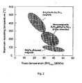
図2〜4は、本発明にしたがって製造されたナノコンポジットNd-Fe-B/Sm-Co磁石の最高実用温度、(BH)maxの温度係数、および最大エネルギー積を、現行磁石の性能と比較して示している。 Figures 2-4 compare the maximum practical temperature, temperature coefficient of (BH) max , and maximum energy product of nanocomposite Nd-Fe-B / Sm-Co magnets made according to the present invention with the performance of current magnets As shown.
図5は、等方性のNd2Fe14B/Sm2(Co,Fe)17磁石〔80重量%のNd2Fe14B+20重量%のSm2(Co,Fe)17、[80重量%/20重量%]として表示〕、および異なった熱変形量を有する異方性のNd2Fe14B/Sm2(Co,Fe)17磁石[80重量%/20重量%]の減磁曲線を示している。 FIG. 5 shows an isotropic Nd 2 Fe 14 B / Sm 2 (Co, Fe) 17 magnet (80 wt% Nd 2 Fe 14 B + 20 wt% Sm 2 (Co, Fe) 17 , [80 wt. % / 20 wt%], and demagnetization curves of anisotropic Nd 2 Fe 14 B / Sm 2 (Co, Fe) 17 magnets [80 wt% / 20 wt%] with different thermal deformations Is shown.
この図では、等方性のナノコンポジット磁石が、15KOeという高い固有保磁力と14MGOeの(BH)maxを有する。熱変形量が40%の異方性ナノコンポジット磁石は、20MGOeの(BH)maxを有する。図5からわかるように、熱変形量を増大させることによって磁化が大幅に増大しており、このことは、熱変形処理を行うことによって異方性のナノコンポジットNd2Fe14B/Sm2(Co,Fe)17磁石を容易に得ることができる、ということを示している。固有保磁力は熱変形処理後に減少する傾向があるけれども、熱変形パラメーターを最適化することによって(たとえば、熱変形処理温度を低下させることによって、および/または熱変形処理時間を短くすることによって)保磁力を向上させることができる、ということを我々は見出した。 In this figure, the isotropic nanocomposite magnet has a high intrinsic coercivity of 15 KOe and (BH) max of 14 MGOe. An anisotropic nanocomposite magnet with a thermal deformation of 40% has a (BH) max of 20 MGOe. As can be seen from FIG. 5, the magnetization is greatly increased by increasing the amount of thermal deformation. This is because the anisotropic nanocomposite Nd 2 Fe 14 B / Sm 2 ( Co, Fe) 17 magnets can be easily obtained. Intrinsic coercivity tends to decrease after thermal deformation processing, but by optimizing the thermal deformation parameters (e.g. by reducing the thermal deformation processing temperature and / or by shortening the thermal deformation processing time) We have found that the coercivity can be improved.
図6は、熱変形処理したナノコンポジットNd14Fe74.5Co5Ga0.5B6/Sm7.7Co63.7Fe28.6磁石と、ミクロン粒子構造を有する、熱変形処理した従来のコンポジットNd15Fe79B6/Sm(Co,Fe,Cu,Zr)7.4磁石の減磁曲線を示している。 Figure 6 shows a nanocomposite Nd 14 Fe 74.5 Co 5 Ga 0.5 B 6 / Sm 7.7 Co 63.7 Fe 28.6 magnet with heat distortion treatment and a conventional composite Nd 15 Fe 79 B 6 / with micron particle structure. The demagnetization curve of Sm (Co, Fe, Cu, Zr) 7.4 magnet is shown.
図7は、従来の異方性焼結Nd15Fe79B6/Sm(Co,Fe,Cu,Zr)7.4磁石と、従来の異方性焼結Nd2Fe14B/Sm2(Co,Fe)17磁石の減磁曲線を示している。 Figure 7 shows a conventional anisotropic sintered Nd 15 Fe 79 B 6 / Sm (Co, Fe, Cu, Zr) 7.4 magnet and a conventional anisotropic sintered Nd 2 Fe 14 B / Sm 2 (Co, Fe) Demagnetization curve of 17 magnets.
図8は、575℃でホットプレスした後と、50%の高さ減少にて850℃で熱変形処理した後の、ナノコンポジットNd14Fe74.5Co5Ga0.5B6/Sm7.7Co63.7Fe28.6[80重量%/20重量%]磁石の減磁曲線を示している。ホットプレスした等方性磁石の(BH)maxは13.57MGOeであった。熱変形処理した異方性磁石の(BH)maxは17.49MGOeであった。 Figure 8 shows nanocomposite Nd 14 Fe 74.5 Co 5 Ga 0.5 B 6 / Sm 7.7 Co 63.7 Fe 28.6 after hot pressing at 575 ° C and after heat deformation at 850 ° C with a 50% height reduction. [80 wt% / 20 wt%] shows the demagnetization curve of the magnet. The hot-pressed isotropic magnet had a (BH) max of 13.57 MGOe. The (BH) max of the thermally deformed anisotropic magnet was 17.49 MGOe.
図9は、600℃でホットプレスした後と、40%の高さ減少にて850℃で熱変形処理した後の、ナノコンポジットNd14Fe74.5Co5Ga0.5B6/Sm7.7Co63.7Fe28.6[80重量%/20重量%]磁石の減磁曲線を示している。ホットプレスした等方性磁石の(BH)maxは13.14MGOeであり、熱変形処理した異方性磁石の(BH)maxは19.41MGOeであった。 Figure 9 shows the nanocomposite Nd 14 Fe 74.5 Co 5 Ga 0.5 B 6 / Sm 7.7 Co 63.7 Fe 28.6 after hot pressing at 600 ° C and after heat deformation at 850 ° C with a 40% height reduction. [80 wt% / 20 wt%] shows the demagnetization curve of the magnet. (BH) max of isotropic magnets hot pressing is 13.14MGOe, anisotropic magnets thermal deformation processing (BH) max was 19.41MGOe.
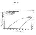
図10は、60%の高さ減少にて880℃で熱変形処理した、異方性のナノコンポジットNd14Fe74.5Co5Ga0.5B6/Sm7.7Co63.7Fe28.6[80重量%/20重量%]磁石の減磁曲線を示している。この磁石の(BH)maxは21.77MGOeであった。 Figure 10 shows anisotropic nanocomposite Nd 14 Fe 74.5 Co 5 Ga 0.5 B 6 / Sm 7.7 Co 63.7 Fe 28.6 [80 wt% / 20 wt %] Shows the demagnetization curve of the magnet. The (BH) max of this magnet was 21.77 MGOe.
図11は、60%の高さ減少にて920℃で熱変形処理した、異方性のナノコンポジットNd14Fe74.5Co5Ga0.5B6/Sm7.7Co63.7Fe28.6[80重量%/20重量%]磁石の減磁曲線を示している。この磁石の(BH)maxは25.20MGOeであった。 Figure 11 shows anisotropic nanocomposite Nd 14 Fe 74.5 Co 5 Ga 0.5 B 6 / Sm 7.7 Co 63.7 Fe 28.6 [80 wt% / 20 wt %] Shows the demagnetization curve of the magnet. The magnet had a (BH) max of 25.20 MGOe.
図12は、60%の高さ減少にて880℃で熱変形処理した、異方性のナノコンポジットNd14Fe74.5Co5Ga0.5B6/Sm7.7Co63.7Fe28.6[80重量%/20重量%]磁石の減磁曲線を示している。この磁石の(BH)maxは27.36MGOeであった。 Figure 12 shows an anisotropic nanocomposite Nd 14 Fe 74.5 Co 5 Ga 0.5 B 6 / Sm 7.7 Co 63.7 Fe 28.6 [80 wt% / 20 wt %] Shows the demagnetization curve of the magnet. The magnet had a (BH) max of 27.36 MGOe.
図13は、71%の高さ減少にて940℃で熱変形処理した、異方性のナノコンポジットPr14Fe73.5Co5Ga0.5B7/Pr16.7Co83.3[80重量%/20重量%]磁石の減磁曲線を示している。この磁石の(BH)maxは32.94MGOeであった。 Fig. 13 shows anisotropic nanocomposite Pr 14 Fe 73.5 Co 5 Ga 0.5 B 7 / Pr 16.7 Co 83.3 [80 wt% / 20 wt%] heat-deformed at 940 ° C with a 71% height reduction The demagnetization curve of a magnet is shown. This magnet had a (BH) max of 32.94 MGOe.
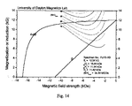
図14は、71%の高さ減少にて920℃で熱変形処理した、異方性のナノコンポジットPr14Fe73.5Co5Ga0.5B7/Pr16.7Co66.6Fe16.7[80重量%/20重量%]磁石の減磁曲線を示している。この磁石の(BH)maxは34.50MGOeであった。 Figure 14 shows an anisotropic nanocomposite Pr 14 Fe 73.5 Co 5 Ga 0.5 B 7 / Pr 16.7 Co 66.6 Fe 16.7 [80 wt% / 20 wt% heat-treated at 920 ° C with a 71% height reduction %] Shows the demagnetization curve of the magnet. This magnet had a (BH) max of 34.50 MGOe.
図15は、ナノ粒子のNd14Fe74.5Co5Ga0.5B6磁石とSm7.7Co63.7Fe28.6磁石、および2種のナノコンポジットNd14Fe74.5Co5Ga0.5B6/Sm7.7Co63.7Fe28.6磁石の、磁束の温度係数と温度の関係を示している。 Figure 15 shows the nanoparticle Nd 14 Fe 74.5 Co 5 Ga 0.5 B 6 magnet and Sm 7.7 Co 63.7 Fe 28.6 magnet, and two nanocomposites Nd 14 Fe 74.5 Co 5 Ga 0.5 B 6 / Sm 7.7 Co 63.7 Fe 28.6 The relationship between the temperature coefficient of magnetic flux and temperature of a magnet is shown.
図16は、ナノコンポジットNd14Fe74.5Co5Ga0.5B6/Sm7.7Co63.7Fe28.6[60重量%/40重量%]磁石の固有保磁力の温度依存性を示している。 FIG. 16 shows the temperature dependence of the intrinsic coercivity of the nanocomposite Nd 14 Fe 74.5 Co 5 Ga 0.5 B 6 / Sm 7.7 Co 63.7 Fe 28.6 [60 wt% / 40 wt%] magnet.
図17は、ナノコンポジットNd14Fe74.5Co5Ga0.5B6/Sm7.7Co63.7Fe28.6[80重量%/20重量%]磁石に対する、低い磁界磁化(low field magnetization)と温度との関係を示している。 Figure 17 shows the relationship between low field magnetization and temperature for a nanocomposite Nd 14 Fe 74.5 Co 5 Ga 0.5 B 6 / Sm 7.7 Co 63.7 Fe 28.6 [80 wt% / 20 wt%] magnet. ing.
図18は、熱変形処理したNd14Fe74.5Co5Ga0.5B6/Sm7.7Co63.7Fe28.6[80重量%/20重量%]磁石の破断面の走査型電子顕微鏡写真である。 FIG. 18 is a scanning electron micrograph of a fracture surface of a thermally deformed Nd 14 Fe 74.5 Co 5 Ga 0.5 B 6 / Sm 7.7 Co 63.7 Fe 28.6 [80 wt% / 20 wt%] magnet.
図19は、ナノコンポジットNd14Fe74.5Co5Ga0.5B6/Sm7.7Co63.7Fe28.6[80重量%/20重量%]磁石の長時間エージング実験の結果を示している。 FIG. 19 shows the results of a long-term aging experiment of the nanocomposite Nd 14 Fe 74.5 Co 5 Ga 0.5 B 6 / Sm 7.7 Co 63.7 Fe 28.6 [80 wt% / 20 wt%] magnet.
表1は、異なった方法を使用して合成したNd-Fe-B/Sm-Co[80重量%/20重量%]複合磁石とPr-Fe-B/Pr-Co複合磁石の比較を示している。 Table 1 shows a comparison of Nd-Fe-B / Sm-Co [80 wt% / 20 wt%] composite magnets and Pr-Fe-B / Pr-Co composite magnets synthesized using different methods. Yes.

本発明を例証するために特定の代表的な実施態様を詳細に示してきたが、添付の特許請求の範囲に規定されている本発明の要旨を逸脱しない範囲において各種の変更を行ってよい、ということは当業者にとって言うまでもないことである。 While certain representative embodiments have been shown in detail to illustrate the present invention, various modifications may be made without departing from the spirit of the invention as defined in the appended claims. It goes without saying to those skilled in the art.
Claims (53)
少なくとも2種の希土類もしくはイットリウム遷移金属の合金粉末を供給する工程、希土類もしくはイットリウム遷移金属の合金は、希土類もしくはイットリウム遷移金属化合物を含む;
少なくとも2種の希土類もしくはイットリウム遷移金属の合金粉末をブレンドする工程;および
少なくとも2種の希土類もしくはイットリウム遷移金属の合金粉末をホットプレスして、等方性のナノコンポジット希土類永久磁石を形成させる工程;
を含む前記製造法。 Comprise at least two rare earth or yttrium transition metal compound, each in R x T 100-xy M y ( wherein the transition metal compounds, R is one or more rare earth, yttrium, or combinations thereof, T is selected from one or more transition metals; M is selected from one or more elements in Group IIIA, Group IVA, or Group VA; x is 3-18; nanocomposite rare earth permanent magnets defined in atomic percentages of y to 0-20, wherein at least two rare earth or yttrium transition metal compounds are of different types or contain different R The nanocomposite rare earth permanent magnet has a structure selected from an isotropic structure or an anisotropic structure, has an average particle size in the range of about 1 nm to about 1000 nm, and Range of about 130 ° C to about 300 ° C A method for producing the nanocomposite rare earth permanent magnet having the highest practical temperature in a range,
Supplying an alloy powder of at least two rare earth or yttrium transition metals, the rare earth or yttrium transition metal alloy comprising a rare earth or yttrium transition metal compound;
Blending at least two rare earth or yttrium transition metal alloy powders; and hot pressing at least two rare earth or yttrium transition metal alloy powders to form an isotropic nanocomposite rare earth permanent magnet;
The said manufacturing method containing.
希土類もしくはイットリウム遷移金属の合金を作製する工程;および
希土類もしくはイットリウム遷移金属の合金粉末を作製する工程;
を含む、請求項19に記載の製造法。 Supplying at least two rare earth or yttrium transition metal alloy powders,
Producing a rare earth or yttrium transition metal alloy; and producing a rare earth or yttrium transition metal alloy powder;
The production method according to claim 19, comprising:
異方性粉末材料と結合剤とを混合して異方性の接合永久磁石を作製する工程;
をさらに含む、請求項19に記載の製造法。 Crushing anisotropic nanocomposite permanent magnets to produce anisotropic powder materials; and mixing anisotropic powder materials and binders to produce anisotropic bonded permanent magnets;
20. The production method according to claim 19, further comprising:
少なくとも2種の希土類もしくはイットリウム遷移金属の合金粉末を供給する工程、希土類もしくはイットリウム遷移金属の合金は、希土類もしくはイットリウム遷移金属化合物を含む;
少なくとも2種の希土類もしくはイットリウム遷移金属の合金粉末をブレンドする工程;
ブレンドした希土類もしくはイットリウム遷移金属の合金を、対応する非晶質アモルファス合金の結晶化温度未満の温度で圧縮して、圧縮粉を作製する工程;および
圧縮粉を熱変形処理して、異方性のナノコンポジット希土類永久磁石を作製する工程;
を含む前記製造法。 Comprise at least two rare earth or yttrium transition metal compound, each in R x T 100-xy M y ( wherein the transition metal compounds, R is one or more rare earth, yttrium, or combinations thereof, T is selected from one or more transition metals; M is selected from one or more elements in Group IIIA, Group IVA, or Group VA; x is 3-18; nanocomposite rare earth permanent magnets defined in atomic percentages of y to 0-20, wherein at least two rare earth or yttrium transition metal compounds are of different types or contain different R The nanocomposite rare earth permanent magnet has a structure selected from an isotropic structure or an anisotropic structure, has an average particle size in the range of about 1 nm to about 1000 nm, and Range of about 130 ° C to about 300 ° C A method for producing the nanocomposite rare earth permanent magnet having the highest practical temperature in a range,
Supplying an alloy powder of at least two rare earth or yttrium transition metals, the rare earth or yttrium transition metal alloy comprising a rare earth or yttrium transition metal compound;
Blending at least two rare earth or yttrium transition metal alloy powders;
Compressing the blended rare earth or yttrium transition metal alloy at a temperature below the crystallization temperature of the corresponding amorphous amorphous alloy to produce a compacted powder; Producing a nanocomposite rare earth permanent magnet of
The said manufacturing method containing.
希土類もしくはイットリウム遷移金属の合金を作製する工程;および
希土類もしくはイットリウム遷移金属の合金粉末を作製する工程;
を含む、請求項34に記載の製造法。 Supplying at least two rare earth or yttrium transition metal alloy powders,
Producing a rare earth or yttrium transition metal alloy; and producing a rare earth or yttrium transition metal alloy powder;
35. The method of claim 34, comprising:
異方性粉末材料と結合剤とを混合して異方性の接合永久磁石を作製する工程;
をさらに含む、請求項34に記載の製造法。 Crushing anisotropic nanocomposite permanent magnets to produce anisotropic powder materials; and mixing anisotropic powder materials and binders to produce anisotropic bonded permanent magnets;
35. The method of claim 34, further comprising:
少なくとも2種の希土類もしくはイットリウム遷移金属の合金粉末を供給する工程、希土類もしくはイットリウム遷移金属の合金は、希土類もしくはイットリウム遷移金属化合物を含む;
少なくとも2種の希土類もしくはイットリウム遷移金属の合金粉末をブレンドする工程;および
ブレンドした合金を容器中で熱変形処理して、異方性のナノコンポジット希土類永久磁石を作製する工程;
を含む前記製造法。 Comprise at least two rare earth or yttrium transition metal compound, each in R x T 100-xy M y ( wherein the transition metal compounds, R is one or more rare earth, yttrium, or combinations thereof, T is selected from one or more transition metals; M is selected from one or more elements in Group IIIA, Group IVA, or Group VA; x is 3-18; nanocomposite rare earth permanent magnets defined in atomic percentages of y to 0-20, wherein at least two rare earth or yttrium transition metal compounds are of different types or contain different R The nanocomposite rare earth permanent magnet has a structure selected from an isotropic structure or an anisotropic structure, has an average particle size in the range of about 1 nm to about 1000 nm, and Range of about 130 ° C to about 300 ° C A method for producing the nanocomposite rare earth permanent magnet having the highest practical temperature in a range,
Supplying an alloy powder of at least two rare earth or yttrium transition metals, the rare earth or yttrium transition metal alloy comprising a rare earth or yttrium transition metal compound;
Blending at least two rare earth or yttrium transition metal alloy powders; and thermally deforming the blended alloy in a container to produce anisotropic nanocomposite rare earth permanent magnets;
The said manufacturing method containing.
希土類もしくはイットリウム遷移金属の合金を作製する工程;および
希土類もしくはイットリウム遷移金属の合金粉末を作製する工程;
を含む、請求項45に記載の製造法。 Supplying at least two rare earth or yttrium transition metal alloy powders,
Producing a rare earth or yttrium transition metal alloy; and producing a rare earth or yttrium transition metal alloy powder;
46. The method according to claim 45, comprising:
異方性粉末材料と結合剤とを混合して異方性の接合永久磁石を作製する工程;
をさらに含む、請求項45に記載の製造法。 Crushing anisotropic nanocomposite permanent magnets to produce anisotropic powder materials; and mixing anisotropic powder materials and binders to produce anisotropic bonded permanent magnets;
46. The method according to claim 45, further comprising:
Applications Claiming Priority (3)
| Application Number | Priority Date | Filing Date | Title |
|---|---|---|---|
| US53367403P | 2003-12-31 | 2003-12-31 | |
| US11/024,590 US20060054245A1 (en) | 2003-12-31 | 2004-12-29 | Nanocomposite permanent magnets |
| PCT/US2004/043993 WO2005066980A2 (en) | 2003-12-31 | 2004-12-30 | Nanocomposite permanent magnets |
Publications (2)
| Publication Number | Publication Date |
|---|---|
| JP2007517414A true JP2007517414A (en) | 2007-06-28 |
| JP2007517414A5 JP2007517414A5 (en) | 2007-10-11 |
Family
ID=34752441
Family Applications (1)
| Application Number | Title | Priority Date | Filing Date |
|---|---|---|---|
| JP2006547583A Pending JP2007517414A (en) | 2003-12-31 | 2004-12-30 | Nano composite permanent magnet |
Country Status (5)
| Country | Link |
|---|---|
| US (1) | US20060054245A1 (en) |
| EP (1) | EP1704573A2 (en) |
| JP (1) | JP2007517414A (en) |
| TW (1) | TW200535873A (en) |
| WO (1) | WO2005066980A2 (en) |
Cited By (8)
| Publication number | Priority date | Publication date | Assignee | Title |
|---|---|---|---|---|
| WO2012032961A1 (en) * | 2010-09-06 | 2012-03-15 | ダイハツ工業株式会社 | Magnetic material and method for producing same |
| JP2013098319A (en) * | 2011-10-31 | 2013-05-20 | Toyota Motor Corp | METHOD FOR MANUFACTURING Nd-Fe-B MAGNET |
| CN104150891A (en) * | 2014-03-15 | 2014-11-19 | 南通万宝磁石制造有限公司 | Preparation technology of ferrite permanent magnet for permanent magnet alternating current synchronous motor |
| KR101740165B1 (en) * | 2012-11-02 | 2017-05-25 | 도요타 지도샤(주) | Rare earth magnet and method for producing same |
| US9859055B2 (en) | 2012-10-18 | 2018-01-02 | Toyota Jidosha Kabushiki Kaisha | Manufacturing method for rare-earth magnet |
| JP2018107446A (en) * | 2016-12-27 | 2018-07-05 | 有研稀土新材料股▲フン▼有限公司 | Rare earth permanent magnet material and manufacturing method thereof |
| US10199145B2 (en) | 2011-11-14 | 2019-02-05 | Toyota Jidosha Kabushiki Kaisha | Rare-earth magnet and method for producing the same |
| US10468165B2 (en) | 2013-06-05 | 2019-11-05 | Toyota Jidosha Kabushiki Kaisha | Rare-earth magnet and method for manufacturing same |
Families Citing this family (22)
| Publication number | Priority date | Publication date | Assignee | Title |
|---|---|---|---|---|
| US7254133B2 (en) * | 2002-07-15 | 2007-08-07 | Intel Corporation | Prevention of denial of service attacks |
| KR101088535B1 (en) | 2007-02-12 | 2011-12-05 | 바쿰슈멜체 게엠베하 운트 코. 카게 | Article for magnetic heat exchange and method of manufacturing the same |
| WO2009090442A1 (en) | 2007-12-27 | 2009-07-23 | Vacuumschmelze Gmbh & Co. Kg | Composite article with magnetocalorically active material and method for its production |
| GB2463931B (en) * | 2008-10-01 | 2011-01-12 | Vacuumschmelze Gmbh & Co Kg | Method for producing a magnetic article |
| WO2010038098A1 (en) | 2008-10-01 | 2010-04-08 | Vacuumschmelze Gmbh & Co. Kg | Article comprising at least one magnetocalorically active phase and method of working an article comprising at least one magnetocalorically active phase |
| WO2010107387A1 (en) * | 2009-03-17 | 2010-09-23 | Magnequench International, Inc. | A magnetic material |
| GB2475985B (en) | 2009-05-06 | 2012-03-21 | Vacuumschmelze Gmbh & Co Kg | Article for magnetic heat exchange and method of fabricating an article for magnetic heat exchange |
| GB2482880B (en) | 2010-08-18 | 2014-01-29 | Vacuumschmelze Gmbh & Co Kg | An article for magnetic heat exchange and a method of fabricating a working component for magnetic heat exchange |
| CN102324814B (en) * | 2011-08-26 | 2013-08-28 | 邓上云 | Preparation process of neodymium-iron-boron /ferrite composite magnet body for permanent magnet alternating current synchronous motor |
| CN102403079A (en) * | 2011-11-17 | 2012-04-04 | 中国科学院宁波材料技术与工程研究所 | Preparation method of anisotropic nanocrystalline neodymium iron boron permanent magnet material |
| DE112012005566T8 (en) * | 2012-01-04 | 2014-11-13 | National Institute For Materials Science | Seltenerdnanoverbundmagnet |
| KR20150033423A (en) * | 2013-09-24 | 2015-04-01 | 엘지전자 주식회사 | Method for fabricating anisotropic permanent hot-deformed magnet using hot deformaion and the magnet fabricated thereby |
| US9687037B1 (en) * | 2014-02-06 | 2017-06-27 | Virginia Commonwealth University | Magnetic football helmet to reduce concussion injuries |
| JP6003920B2 (en) | 2014-02-12 | 2016-10-05 | トヨタ自動車株式会社 | Rare earth magnet manufacturing method |
| RU2578211C1 (en) * | 2014-10-29 | 2016-03-27 | Федеральное государственное унитарное предприятие "Всероссийский научно-исследовательский институт авиационных материалов" (ФГУП "ВИАМ") | Magnetic material for permanent magnets and item made from it |
| US10062482B2 (en) | 2015-08-25 | 2018-08-28 | GM Global Technology Operations LLC | Rapid consolidation method for preparing bulk metastable iron-rich materials |
| CN106531382B (en) | 2015-09-10 | 2019-11-05 | 燕山大学 | A kind of permanent-magnet material and preparation method thereof |
| WO2018035202A1 (en) | 2016-08-17 | 2018-02-22 | Urban Mining Technology Company, Inc. | Caster assembly |
| EP3858515A1 (en) * | 2020-01-30 | 2021-08-04 | Jozef Stefan Institute | Filament with oriented magnetic particles for 3d printing of anisotropic magnets |
| CN113205937B (en) * | 2021-04-23 | 2022-10-04 | 安徽吉华新材料有限公司 | Heavy-rare-earth-free high-performance sintered neodymium-iron-boron permanent magnet material and preparation process thereof |
| CN113205938B (en) * | 2021-04-23 | 2022-10-14 | 安徽吉华新材料有限公司 | Low-cost high-performance sintered neodymium-iron-boron permanent magnet material and preparation process thereof |
| CN113903585B (en) * | 2021-09-07 | 2023-10-03 | 江西理工大学 | Rare earth permanent magnet material with anisotropy and preparation method thereof |
Citations (1)
| Publication number | Priority date | Publication date | Assignee | Title |
|---|---|---|---|---|
| JP2000147079A (en) * | 1998-11-17 | 2000-05-26 | Alps Electric Co Ltd | Magnetic sensor and manufacture thereof |
Family Cites Families (60)
| Publication number | Priority date | Publication date | Assignee | Title |
|---|---|---|---|---|
| US3558372A (en) * | 1968-01-31 | 1971-01-26 | Gen Electric | Method of making permanent magnet material powders |
| US3560200A (en) * | 1968-04-01 | 1971-02-02 | Bell Telephone Labor Inc | Permanent magnetic materials |
| US3919004A (en) * | 1970-04-30 | 1975-11-11 | Gen Electric | Liquid sintered cobalt-rare earth intermetallic product |
| US4375372A (en) * | 1972-03-16 | 1983-03-01 | The United States Of America As Represented By The Secretary Of The Navy | Use of cubic rare earth-iron laves phase intermetallic compounds as magnetostrictive transducer materials |
| US3985588A (en) * | 1975-02-03 | 1976-10-12 | Cambridge Thermionic Corporation | Spinning mold method for making permanent magnets |
| US4289549A (en) * | 1978-10-31 | 1981-09-15 | Kabushiki Kaisha Suwa Seikosha | Resin bonded permanent magnet composition |
| US4409043A (en) * | 1981-10-23 | 1983-10-11 | The United States Of America As Represented By The Secretary Of The Navy | Amorphous transition metal-lanthanide alloys |
| US4533408A (en) * | 1981-10-23 | 1985-08-06 | Koon Norman C | Preparation of hard magnetic alloys of a transition metal and lanthanide |
| US4402770A (en) * | 1981-10-23 | 1983-09-06 | The United States Of America As Represented By The Secretary Of The Navy | Hard magnetic alloys of a transition metal and lanthanide |
| CA1316375C (en) * | 1982-08-21 | 1993-04-20 | Masato Sagawa | Magnetic materials and permanent magnets |
| DE3379131D1 (en) * | 1982-09-03 | 1989-03-09 | Gen Motors Corp | Re-tm-b alloys, method for their production and permanent magnets containing such alloys |
| US4597938A (en) * | 1983-05-21 | 1986-07-01 | Sumitomo Special Metals Co., Ltd. | Process for producing permanent magnet materials |
| JPS6032306A (en) * | 1983-08-02 | 1985-02-19 | Sumitomo Special Metals Co Ltd | Permanent magnet |
| EP0156482B1 (en) * | 1984-02-13 | 1989-05-24 | Sherritt Gordon Limited | Sm2co17 alloys suitable for use as permanent magnets |
| EP0153744B1 (en) * | 1984-02-28 | 1990-01-03 | Sumitomo Special Metals Co., Ltd. | Process for producing permanent magnets |
| US4558077A (en) * | 1984-03-08 | 1985-12-10 | General Motors Corporation | Epoxy bonded rare earth-iron magnets |
| US4710239A (en) * | 1984-09-14 | 1987-12-01 | General Motors Corporation | Hot pressed permanent magnet having high and low coercivity regions |
| US6136099A (en) * | 1985-08-13 | 2000-10-24 | Seiko Epson Corporation | Rare earth-iron series permanent magnets and method of preparation |
| US5538565A (en) * | 1985-08-13 | 1996-07-23 | Seiko Epson Corporation | Rare earth cast alloy permanent magnets and methods of preparation |
| KR900006533B1 (en) * | 1987-01-06 | 1990-09-07 | 히다찌 긴조꾸 가부시끼가이샤 | Anisotropic magnetic materials and magnets made with it and making method for it |
| US5173206A (en) * | 1987-12-14 | 1992-12-22 | The B. F. Goodrich Company | Passivated rare earth magnet or magnetic material compositions |
| US4988755A (en) * | 1987-12-14 | 1991-01-29 | The B. F. Goodrich Company | Passivated rare earth magnet or magnetic material compositions |
| US4975213A (en) * | 1988-01-19 | 1990-12-04 | Kabushiki Kaisha Toshiba | Resin-bonded rare earth-iron-boron magnet |
| JP2741508B2 (en) * | 1988-02-29 | 1998-04-22 | 住友特殊金属株式会社 | Magnetic anisotropic sintered magnet and method of manufacturing the same |
| US4859410A (en) * | 1988-03-24 | 1989-08-22 | General Motors Corporation | Die-upset manufacture to produce high volume fractions of RE-Fe-B type magnetically aligned material |
| FR2640828A1 (en) * | 1988-07-21 | 1990-06-22 | Seiko Epson Corp | ELECTROMAGNETIC ACTUATOR |
| US4881985A (en) * | 1988-08-05 | 1989-11-21 | General Motors Corporation | Method for producing anisotropic RE-FE-B type magnetically aligned material |
| JPH02288305A (en) * | 1989-04-28 | 1990-11-28 | Nippon Steel Corp | Rare earth magnet and manufacture thereof |
| JP2596835B2 (en) * | 1989-08-04 | 1997-04-02 | 新日本製鐵株式会社 | Rare earth anisotropic powder and rare earth anisotropic magnet |
| US5051200A (en) * | 1989-09-19 | 1991-09-24 | The B. F. Goodrich Company | Flexible high energy magnetic blend compositions based on rare earth magnetic particles in highly saturated nitrile rubber |
| US5201963A (en) * | 1989-10-26 | 1993-04-13 | Nippon Steel Corporation | Rare earth magnets and method of producing same |
| US5037492A (en) * | 1989-12-19 | 1991-08-06 | General Motors Corporation | Alloying low-level additives into hot-worked Nd-Fe-B magnets |
| US5085716A (en) * | 1990-02-20 | 1992-02-04 | General Motors Corporation | Hot worked rare earth-iron-carbon magnets |
| DE69434323T2 (en) * | 1993-11-02 | 2006-03-09 | Tdk Corp. | Preparation d'un aimant permanent |
| US5858123A (en) * | 1995-07-12 | 1999-01-12 | Hitachi Metals, Ltd. | Rare earth permanent magnet and method for producing the same |
| US5567757A (en) * | 1995-07-18 | 1996-10-22 | Rjf International Corporation | Low specific gravity binder for magnets |
| US5725792A (en) * | 1996-04-10 | 1998-03-10 | Magnequench International, Inc. | Bonded magnet with low losses and easy saturation |
| US5976271A (en) * | 1997-04-21 | 1999-11-02 | Shin-Etsu Chemical Co., Ltd. | Method for the preparation of rare earth based anisotropic permanent magnet |
| JPH1197222A (en) * | 1997-09-19 | 1999-04-09 | Shin Etsu Chem Co Ltd | Anisotropic rare earth permanent magnet material and magnet powder |
| JP3470032B2 (en) * | 1997-12-22 | 2003-11-25 | 信越化学工業株式会社 | Rare earth permanent magnet material and manufacturing method thereof |
| US6425961B1 (en) * | 1998-05-15 | 2002-07-30 | Alps Electric Co., Ltd. | Composite hard magnetic material and method for producing the same |
| US6302972B1 (en) * | 1998-12-07 | 2001-10-16 | Sumitomo Special Metals Co., Ltd | Nanocomposite magnet material and method for producing nanocomposite magnet |
| JP2001076914A (en) * | 1998-12-17 | 2001-03-23 | Sumitomo Special Metals Co Ltd | Rare-earth based permanent magnet and manufacture thereof |
| US6319334B1 (en) * | 1998-12-17 | 2001-11-20 | Shin-Etsu Chemical Co., Ltd. | Rare earth/iron/boron-based permanent magnet and method for the preparation thereof |
| JP3275882B2 (en) * | 1999-07-22 | 2002-04-22 | セイコーエプソン株式会社 | Magnet powder and isotropic bonded magnet |
| JP3159693B1 (en) * | 1999-08-30 | 2001-04-23 | 住友特殊金属株式会社 | Method for producing rare earth permanent magnet having corrosion resistant coating |
| US6277211B1 (en) * | 1999-09-30 | 2001-08-21 | Magnequench Inc. | Cu additions to Nd-Fe-B alloys to reduce oxygen content in the ingot and rapidly solidified ribbon |
| US20020036367A1 (en) * | 2000-02-22 | 2002-03-28 | Marlin Walmer | Method for producing & manufacturing density enhanced, DMC, bonded permanent magnets |
| WO2001091139A1 (en) * | 2000-05-24 | 2001-11-29 | Sumitomo Special Metals Co., Ltd. | Permanent magnet including multiple ferromagnetic phases and method for producing the magnet |
| TW503409B (en) * | 2000-05-29 | 2002-09-21 | Daido Steel Co Ltd | Isotropic powdery magnet material, process for preparing and resin-bonded magnet |
| JP3611108B2 (en) * | 2000-05-30 | 2005-01-19 | セイコーエプソン株式会社 | Cooling roll and ribbon magnet material |
| US7217328B2 (en) * | 2000-11-13 | 2007-05-15 | Neomax Co., Ltd. | Compound for rare-earth bonded magnet and bonded magnet using the compound |
| US6790296B2 (en) * | 2000-11-13 | 2004-09-14 | Neomax Co., Ltd. | Nanocomposite magnet and method for producing same |
| JP3983999B2 (en) * | 2001-05-17 | 2007-09-26 | 日産自動車株式会社 | Manufacturing method of anisotropic exchange spring magnet and motor comprising the same |
| US6833036B2 (en) * | 2001-06-29 | 2004-12-21 | Tdk Corporation | Rare earth permanent magnet |
| US6855426B2 (en) * | 2001-08-08 | 2005-02-15 | Nanoproducts Corporation | Methods for producing composite nanoparticles |
| AU2002358316A1 (en) * | 2001-12-18 | 2003-06-30 | Showa Denko K.K. | Alloy flake for rare earth magnet, production method thereof, alloy powder for rare earth sintered magnet, rare earth sintered magnet, alloy powder for bonded magnet and bonded magnet |
| WO2003085683A1 (en) * | 2002-04-09 | 2003-10-16 | Aichi Steel Corporation | Composite rare earth anisotropic bonded magnet, compound for composite rare earth anisotropic bonded magnet and method for preparation thereof |
| US20040025974A1 (en) * | 2002-05-24 | 2004-02-12 | Don Lee | Nanocrystalline and nanocomposite rare earth permanent magnet materials and method of making the same |
| CN1985338A (en) * | 2004-06-30 | 2007-06-20 | 代顿大学 | Anisotropic nanocomposite rare earth permanent magnets and method of making |
-
2004
- 2004-12-29 US US11/024,590 patent/US20060054245A1/en not_active Abandoned
- 2004-12-30 JP JP2006547583A patent/JP2007517414A/en active Pending
- 2004-12-30 WO PCT/US2004/043993 patent/WO2005066980A2/en active Application Filing
- 2004-12-30 EP EP04815980A patent/EP1704573A2/en not_active Withdrawn
- 2004-12-31 TW TW093141815A patent/TW200535873A/en unknown
Patent Citations (1)
| Publication number | Priority date | Publication date | Assignee | Title |
|---|---|---|---|---|
| JP2000147079A (en) * | 1998-11-17 | 2000-05-26 | Alps Electric Co Ltd | Magnetic sensor and manufacture thereof |
Cited By (9)
| Publication number | Priority date | Publication date | Assignee | Title |
|---|---|---|---|---|
| WO2012032961A1 (en) * | 2010-09-06 | 2012-03-15 | ダイハツ工業株式会社 | Magnetic material and method for producing same |
| JP2013098319A (en) * | 2011-10-31 | 2013-05-20 | Toyota Motor Corp | METHOD FOR MANUFACTURING Nd-Fe-B MAGNET |
| US10199145B2 (en) | 2011-11-14 | 2019-02-05 | Toyota Jidosha Kabushiki Kaisha | Rare-earth magnet and method for producing the same |
| US9859055B2 (en) | 2012-10-18 | 2018-01-02 | Toyota Jidosha Kabushiki Kaisha | Manufacturing method for rare-earth magnet |
| KR101740165B1 (en) * | 2012-11-02 | 2017-05-25 | 도요타 지도샤(주) | Rare earth magnet and method for producing same |
| US10468165B2 (en) | 2013-06-05 | 2019-11-05 | Toyota Jidosha Kabushiki Kaisha | Rare-earth magnet and method for manufacturing same |
| US10748684B2 (en) | 2013-06-05 | 2020-08-18 | Toyota Jidosha Kabushiki Kaisha | Rare-earth magnet and method for manufacturing same |
| CN104150891A (en) * | 2014-03-15 | 2014-11-19 | 南通万宝磁石制造有限公司 | Preparation technology of ferrite permanent magnet for permanent magnet alternating current synchronous motor |
| JP2018107446A (en) * | 2016-12-27 | 2018-07-05 | 有研稀土新材料股▲フン▼有限公司 | Rare earth permanent magnet material and manufacturing method thereof |
Also Published As
| Publication number | Publication date |
|---|---|
| WO2005066980A3 (en) | 2005-09-15 |
| US20060054245A1 (en) | 2006-03-16 |
| EP1704573A2 (en) | 2006-09-27 |
| WO2005066980A2 (en) | 2005-07-21 |
| TW200535873A (en) | 2005-11-01 |
Similar Documents
| Publication | Publication Date | Title |
|---|---|---|
| JP2007517414A (en) | Nano composite permanent magnet | |
| US20060005898A1 (en) | Anisotropic nanocomposite rare earth permanent magnets and method of making | |
| Rong et al. | Nanocrystalline and nanocomposite permanent magnets by melt spinning technique | |
| US6413327B1 (en) | Nitride type, rare earth magnet materials and bonded magnets formed therefrom | |
| JP2005527989A (en) | Nanocrystalline rare earth permanent magnet materials, nanocomposite rare earth permanent magnet materials, and methods for producing these magnet materials | |
| JP2018093202A (en) | R-t-b based permanent magnet | |
| CN1309811A (en) | High performance iron-rare earth-boron-refractory-cobalt nanocomposites | |
| JP5504832B2 (en) | Manufacturing method of nanocomposite magnet | |
| JP6471669B2 (en) | Manufacturing method of RTB-based magnet | |
| JPH0366105A (en) | Rare earth anisotropic powder and magnet, and manufacture thereof | |
| WO1988006797A1 (en) | Rare earth element-iron base permanent magnet and process for its production | |
| CN110753978B (en) | Thermally deformable magnet and method for producing same | |
| Liu et al. | Compositional optimization and new processes for nanocrystalline NdFeB-based permanent magnets | |
| KR102605565B1 (en) | Method of manufacturing anisotropic rare earth bulk magnet and anisotropic rare earth bulk magnet therefrom | |
| WO2004046409A2 (en) | Permanent magnet alloy with improved high temperature performance | |
| JPH045740B2 (en) | ||
| Yang et al. | High coercivity of Nd–Dy–Fe–(C, B) ribbons prepared by melt spinning | |
| JP2001135509A (en) | Isotropic rare earth magnet material, isotropic bond magnet, rotating machine and magnet roll | |
| CN1961388A (en) | Nanocomposite permanent magnets | |
| JPH045739B2 (en) | ||
| JP2586199B2 (en) | Rare earth-Fe-Co-B permanent magnet powder and bonded magnet with excellent magnetic anisotropy and corrosion resistance | |
| WO2017191790A1 (en) | Rare-earth permanent magnet, and method for manufacturing same | |
| CN116230346B (en) | Anisotropic nanocrystalline rare earth permanent magnet and preparation method thereof | |
| US20120001711A1 (en) | Permanent magnet with low or no dysprosium for high temperature performance | |
| JPH0320048B2 (en) |
Legal Events
| Date | Code | Title | Description |
|---|---|---|---|
| A521 | Request for written amendment filed |
Free format text: JAPANESE INTERMEDIATE CODE: A523 Effective date: 20070814 |
|
| A621 | Written request for application examination |
Free format text: JAPANESE INTERMEDIATE CODE: A621 Effective date: 20070814 |
|
| A977 | Report on retrieval |
Free format text: JAPANESE INTERMEDIATE CODE: A971007 Effective date: 20091023 |
|
| A131 | Notification of reasons for refusal |
Free format text: JAPANESE INTERMEDIATE CODE: A131 Effective date: 20091215 |
|
| A02 | Decision of refusal |
Free format text: JAPANESE INTERMEDIATE CODE: A02 Effective date: 20100511 |