JP2007504543A - Apparatus and method for detecting distance to obstacle in automobile - Google Patents
Apparatus and method for detecting distance to obstacle in automobile Download PDFInfo
- Publication number
- JP2007504543A JP2007504543A JP2006525068A JP2006525068A JP2007504543A JP 2007504543 A JP2007504543 A JP 2007504543A JP 2006525068 A JP2006525068 A JP 2006525068A JP 2006525068 A JP2006525068 A JP 2006525068A JP 2007504543 A JP2007504543 A JP 2007504543A
- Authority
- JP
- Japan
- Prior art keywords
- control unit
- vehicle
- distance
- driving path
- automobile
- Prior art date
- Legal status (The legal status is an assumption and is not a legal conclusion. Google has not performed a legal analysis and makes no representation as to the accuracy of the status listed.)
- Abandoned
Links
Images


Classifications
-
- B—PERFORMING OPERATIONS; TRANSPORTING
- B60—VEHICLES IN GENERAL
- B60T—VEHICLE BRAKE CONTROL SYSTEMS OR PARTS THEREOF; BRAKE CONTROL SYSTEMS OR PARTS THEREOF, IN GENERAL; ARRANGEMENT OF BRAKING ELEMENTS ON VEHICLES IN GENERAL; PORTABLE DEVICES FOR PREVENTING UNWANTED MOVEMENT OF VEHICLES; VEHICLE MODIFICATIONS TO FACILITATE COOLING OF BRAKES
- B60T7/00—Brake-action initiating means
- B60T7/12—Brake-action initiating means for automatic initiation; for initiation not subject to will of driver or passenger
- B60T7/22—Brake-action initiating means for automatic initiation; for initiation not subject to will of driver or passenger initiated by contact of vehicle, e.g. bumper, with an external object, e.g. another vehicle, or by means of contactless obstacle detectors mounted on the vehicle
-
- B—PERFORMING OPERATIONS; TRANSPORTING
- B60—VEHICLES IN GENERAL
- B60K—ARRANGEMENT OR MOUNTING OF PROPULSION UNITS OR OF TRANSMISSIONS IN VEHICLES; ARRANGEMENT OR MOUNTING OF PLURAL DIVERSE PRIME-MOVERS IN VEHICLES; AUXILIARY DRIVES FOR VEHICLES; INSTRUMENTATION OR DASHBOARDS FOR VEHICLES; ARRANGEMENTS IN CONNECTION WITH COOLING, AIR INTAKE, GAS EXHAUST OR FUEL SUPPLY OF PROPULSION UNITS IN VEHICLES
- B60K31/00—Vehicle fittings, acting on a single sub-unit only, for automatically controlling vehicle speed, i.e. preventing speed from exceeding an arbitrarily established velocity or maintaining speed at a particular velocity, as selected by the vehicle operator
- B60K31/0008—Vehicle fittings, acting on a single sub-unit only, for automatically controlling vehicle speed, i.e. preventing speed from exceeding an arbitrarily established velocity or maintaining speed at a particular velocity, as selected by the vehicle operator including means for detecting potential obstacles in vehicle path
-
- G—PHYSICS
- G01—MEASURING; TESTING
- G01S—RADIO DIRECTION-FINDING; RADIO NAVIGATION; DETERMINING DISTANCE OR VELOCITY BY USE OF RADIO WAVES; LOCATING OR PRESENCE-DETECTING BY USE OF THE REFLECTION OR RERADIATION OF RADIO WAVES; ANALOGOUS ARRANGEMENTS USING OTHER WAVES
- G01S13/00—Systems using the reflection or reradiation of radio waves, e.g. radar systems; Analogous systems using reflection or reradiation of waves whose nature or wavelength is irrelevant or unspecified
- G01S13/88—Radar or analogous systems specially adapted for specific applications
- G01S13/93—Radar or analogous systems specially adapted for specific applications for anti-collision purposes
- G01S13/931—Radar or analogous systems specially adapted for specific applications for anti-collision purposes of land vehicles
-
- B—PERFORMING OPERATIONS; TRANSPORTING
- B60—VEHICLES IN GENERAL
- B60T—VEHICLE BRAKE CONTROL SYSTEMS OR PARTS THEREOF; BRAKE CONTROL SYSTEMS OR PARTS THEREOF, IN GENERAL; ARRANGEMENT OF BRAKING ELEMENTS ON VEHICLES IN GENERAL; PORTABLE DEVICES FOR PREVENTING UNWANTED MOVEMENT OF VEHICLES; VEHICLE MODIFICATIONS TO FACILITATE COOLING OF BRAKES
- B60T2201/00—Particular use of vehicle brake systems; Special systems using also the brakes; Special software modules within the brake system controller
- B60T2201/02—Active or adaptive cruise control system; Distance control
-
- B—PERFORMING OPERATIONS; TRANSPORTING
- B60—VEHICLES IN GENERAL
- B60T—VEHICLE BRAKE CONTROL SYSTEMS OR PARTS THEREOF; BRAKE CONTROL SYSTEMS OR PARTS THEREOF, IN GENERAL; ARRANGEMENT OF BRAKING ELEMENTS ON VEHICLES IN GENERAL; PORTABLE DEVICES FOR PREVENTING UNWANTED MOVEMENT OF VEHICLES; VEHICLE MODIFICATIONS TO FACILITATE COOLING OF BRAKES
- B60T2201/00—Particular use of vehicle brake systems; Special systems using also the brakes; Special software modules within the brake system controller
- B60T2201/10—Automatic or semi-automatic parking aid systems
-
- B—PERFORMING OPERATIONS; TRANSPORTING
- B60—VEHICLES IN GENERAL
- B60W—CONJOINT CONTROL OF VEHICLE SUB-UNITS OF DIFFERENT TYPE OR DIFFERENT FUNCTION; CONTROL SYSTEMS SPECIALLY ADAPTED FOR HYBRID VEHICLES; ROAD VEHICLE DRIVE CONTROL SYSTEMS FOR PURPOSES NOT RELATED TO THE CONTROL OF A PARTICULAR SUB-UNIT
- B60W2520/00—Input parameters relating to overall vehicle dynamics
- B60W2520/10—Longitudinal speed
- B60W2520/105—Longitudinal acceleration
-
- B—PERFORMING OPERATIONS; TRANSPORTING
- B60—VEHICLES IN GENERAL
- B60W—CONJOINT CONTROL OF VEHICLE SUB-UNITS OF DIFFERENT TYPE OR DIFFERENT FUNCTION; CONTROL SYSTEMS SPECIALLY ADAPTED FOR HYBRID VEHICLES; ROAD VEHICLE DRIVE CONTROL SYSTEMS FOR PURPOSES NOT RELATED TO THE CONTROL OF A PARTICULAR SUB-UNIT
- B60W2540/00—Input parameters relating to occupants
- B60W2540/18—Steering angle
-
- G—PHYSICS
- G01—MEASURING; TESTING
- G01S—RADIO DIRECTION-FINDING; RADIO NAVIGATION; DETERMINING DISTANCE OR VELOCITY BY USE OF RADIO WAVES; LOCATING OR PRESENCE-DETECTING BY USE OF THE REFLECTION OR RERADIATION OF RADIO WAVES; ANALOGOUS ARRANGEMENTS USING OTHER WAVES
- G01S13/00—Systems using the reflection or reradiation of radio waves, e.g. radar systems; Analogous systems using reflection or reradiation of waves whose nature or wavelength is irrelevant or unspecified
- G01S13/87—Combinations of radar systems, e.g. primary radar and secondary radar
-
- G—PHYSICS
- G01—MEASURING; TESTING
- G01S—RADIO DIRECTION-FINDING; RADIO NAVIGATION; DETERMINING DISTANCE OR VELOCITY BY USE OF RADIO WAVES; LOCATING OR PRESENCE-DETECTING BY USE OF THE REFLECTION OR RERADIATION OF RADIO WAVES; ANALOGOUS ARRANGEMENTS USING OTHER WAVES
- G01S13/00—Systems using the reflection or reradiation of radio waves, e.g. radar systems; Analogous systems using reflection or reradiation of waves whose nature or wavelength is irrelevant or unspecified
- G01S13/88—Radar or analogous systems specially adapted for specific applications
- G01S13/93—Radar or analogous systems specially adapted for specific applications for anti-collision purposes
- G01S13/931—Radar or analogous systems specially adapted for specific applications for anti-collision purposes of land vehicles
- G01S2013/9317—Driving backwards
-
- G—PHYSICS
- G01—MEASURING; TESTING
- G01S—RADIO DIRECTION-FINDING; RADIO NAVIGATION; DETERMINING DISTANCE OR VELOCITY BY USE OF RADIO WAVES; LOCATING OR PRESENCE-DETECTING BY USE OF THE REFLECTION OR RERADIATION OF RADIO WAVES; ANALOGOUS ARRANGEMENTS USING OTHER WAVES
- G01S13/00—Systems using the reflection or reradiation of radio waves, e.g. radar systems; Analogous systems using reflection or reradiation of waves whose nature or wavelength is irrelevant or unspecified
- G01S13/88—Radar or analogous systems specially adapted for specific applications
- G01S13/93—Radar or analogous systems specially adapted for specific applications for anti-collision purposes
- G01S13/931—Radar or analogous systems specially adapted for specific applications for anti-collision purposes of land vehicles
- G01S2013/93185—Controlling the brakes
-
- G—PHYSICS
- G01—MEASURING; TESTING
- G01S—RADIO DIRECTION-FINDING; RADIO NAVIGATION; DETERMINING DISTANCE OR VELOCITY BY USE OF RADIO WAVES; LOCATING OR PRESENCE-DETECTING BY USE OF THE REFLECTION OR RERADIATION OF RADIO WAVES; ANALOGOUS ARRANGEMENTS USING OTHER WAVES
- G01S13/00—Systems using the reflection or reradiation of radio waves, e.g. radar systems; Analogous systems using reflection or reradiation of waves whose nature or wavelength is irrelevant or unspecified
- G01S13/88—Radar or analogous systems specially adapted for specific applications
- G01S13/93—Radar or analogous systems specially adapted for specific applications for anti-collision purposes
- G01S13/931—Radar or analogous systems specially adapted for specific applications for anti-collision purposes of land vehicles
- G01S2013/932—Radar or analogous systems specially adapted for specific applications for anti-collision purposes of land vehicles using own vehicle data, e.g. ground speed, steering wheel direction
-
- G—PHYSICS
- G01—MEASURING; TESTING
- G01S—RADIO DIRECTION-FINDING; RADIO NAVIGATION; DETERMINING DISTANCE OR VELOCITY BY USE OF RADIO WAVES; LOCATING OR PRESENCE-DETECTING BY USE OF THE REFLECTION OR RERADIATION OF RADIO WAVES; ANALOGOUS ARRANGEMENTS USING OTHER WAVES
- G01S13/00—Systems using the reflection or reradiation of radio waves, e.g. radar systems; Analogous systems using reflection or reradiation of waves whose nature or wavelength is irrelevant or unspecified
- G01S13/88—Radar or analogous systems specially adapted for specific applications
- G01S13/93—Radar or analogous systems specially adapted for specific applications for anti-collision purposes
- G01S13/931—Radar or analogous systems specially adapted for specific applications for anti-collision purposes of land vehicles
- G01S2013/9324—Alternative operation using ultrasonic waves
-
- G—PHYSICS
- G01—MEASURING; TESTING
- G01S—RADIO DIRECTION-FINDING; RADIO NAVIGATION; DETERMINING DISTANCE OR VELOCITY BY USE OF RADIO WAVES; LOCATING OR PRESENCE-DETECTING BY USE OF THE REFLECTION OR RERADIATION OF RADIO WAVES; ANALOGOUS ARRANGEMENTS USING OTHER WAVES
- G01S13/00—Systems using the reflection or reradiation of radio waves, e.g. radar systems; Analogous systems using reflection or reradiation of waves whose nature or wavelength is irrelevant or unspecified
- G01S13/88—Radar or analogous systems specially adapted for specific applications
- G01S13/93—Radar or analogous systems specially adapted for specific applications for anti-collision purposes
- G01S13/931—Radar or analogous systems specially adapted for specific applications for anti-collision purposes of land vehicles
- G01S2013/9327—Sensor installation details
- G01S2013/93271—Sensor installation details in the front of the vehicles
-
- G—PHYSICS
- G01—MEASURING; TESTING
- G01S—RADIO DIRECTION-FINDING; RADIO NAVIGATION; DETERMINING DISTANCE OR VELOCITY BY USE OF RADIO WAVES; LOCATING OR PRESENCE-DETECTING BY USE OF THE REFLECTION OR RERADIATION OF RADIO WAVES; ANALOGOUS ARRANGEMENTS USING OTHER WAVES
- G01S13/00—Systems using the reflection or reradiation of radio waves, e.g. radar systems; Analogous systems using reflection or reradiation of waves whose nature or wavelength is irrelevant or unspecified
- G01S13/88—Radar or analogous systems specially adapted for specific applications
- G01S13/93—Radar or analogous systems specially adapted for specific applications for anti-collision purposes
- G01S13/931—Radar or analogous systems specially adapted for specific applications for anti-collision purposes of land vehicles
- G01S2013/9327—Sensor installation details
- G01S2013/93272—Sensor installation details in the back of the vehicles
Abstract
本発明は、距離センサ(1〜6)及び制御ユニット(10)を有する、障害物(8、8’)からの自動車(7)の距離(A)を検出する装置(15)に関する。本発明の装置は、制御ユニット(10)が動的車両データを使用して自動車(7)がもうすぐ至る運転経路(11)の計算に適合されることを特徴とする。制御ユニット(10)はまた運転経路(11)内にある関係のある障害物(8’)と運転経路(11)の外部にある無関係な障害物(8)とを区別するのに適している。本発明はまた障害物(8、8’)からの自動車(7)の距離(A)を検出する方法に関する。
The invention relates to a device (15) for detecting the distance (A) of an automobile (7) from an obstacle (8, 8 ') comprising a distance sensor (1-6) and a control unit (10). The device according to the invention is characterized in that the control unit (10) is adapted for the calculation of the driving route (11) that the vehicle (7) is about to take using dynamic vehicle data. The control unit (10) is also suitable for distinguishing between related obstacles (8 ') in the driving path (11) and irrelevant obstacles (8) outside the driving path (11). . The invention also relates to a method for detecting the distance (A) of the car (7) from the obstacle (8, 8 ').
Description
本発明は、請求項1の前段による自動車と障害物との間の距離を検出する装置、さらに請求項9の前段による関連方法に関する。
The invention relates to a device for detecting the distance between an automobile and an obstacle according to the first stage of
一般的な種類の装置は、例えば、出願人の製品に付けられた機能の名称「パークトロニック(Parktronic)」で知られている。このような装置は、車両の進行方向に位置し、さらに車両からの距離が所定限界距離よりも短い障害物について運転者が警告をすることで、特に駐車時など、視界の悪い制限された交通条件での車両の運転者の操作を容易にするために使用できる。このような障害物は、例えば、周囲にある物体又は他の車両のような移動障害物であっても良い。 A common type of device is known, for example, under the name “Parktronic”, which is a function assigned to the applicant's product. Such a device is located in the direction of travel of the vehicle, and the driver warns about an obstacle whose distance from the vehicle is shorter than a predetermined limit distance. It can be used to facilitate the operation of the vehicle driver under conditions. Such an obstacle may be a moving obstacle such as a surrounding object or another vehicle, for example.
特許文献1は、車両と障害物との間の距離を測定する測定装置、評価装置、及び警告信号発信器を有する車両の駐車支援システムを開示している。評価装置は測定装置によって出力された距離信号を距離限界値と比較し、警告信号発信器は、距離信号が距離限界値を上回る限り車両の運転者によって感知できる警告信号を発生する。車両の運動状況の1つの所定機能によれば、評価装置はこの状況において動的に距離限界値を設定する。その結果、それはまた、比較的高速においても車両を衝突物の前で確実に停止させるのに必要な反応時間を運転者に与える。
特許文献2は、物体を検出する装置として、特に自動車内の駐車支援装置としての方法を開示する。装置は、多数の距離センサ、距離センサを作動させる少なくとも1つのマイクロコントローラ、及び出力ユニットを有し、マイクロコントローラが距離センサに、時間によって変化する識別子を加えることが可能である。距離センサに時間によって変化する識別子を加えることによって、受信信号を排他的に発信源と確実に対応させることが可能になる。その結果、例えば、他の車両の距離センサから発せられる信号によって、距離測定が悪影響を受ける危険性が低減される。 Patent Document 2 discloses a method as a device for detecting an object, particularly as a parking assistance device in an automobile. The device has a number of distance sensors, at least one microcontroller for operating the distance sensor, and an output unit, which allows the microcontroller to add to the distance sensor an identifier that varies with time. By adding an identifier that varies with time to the distance sensor, it is possible to ensure that the received signal is exclusively associated with the source. As a result, for example, the risk of the distance measurement being adversely affected by a signal emitted from a distance sensor of another vehicle is reduced.
特許文献3は、エコー法、好ましくは超音波法を用いて車両から障害物の距離を測定する方法を開示しており、伝送信号が放射を受けた物体からエコーの形で車両に跳ね返され、受信器のしきい値の関数として時間的聴取ウインドウ中ごとに車両内で評価され、警告信号が誘発される。伝送信号の時間的順序の位置、期間、聴取ウインドウ中の経時的なしきい値の変化は、車両のデータに依存する。例えば、車両の前輪が特定の角度でロックされた場合、前輪の角度位置のため遠隔領域に到達しない車両側のこの遠隔領域での測定が不要となる。この場合、聴取ウインドウは早期に終了できる。しかしながら、車両の車両運動動的データも、距離測定の測定パラメータを変更するために使用できる。記述の方法は、特に自動車の直近の望ましくないエコーを遮断することが考えられる。この理由で、例えば、超音波センサーの感度は、車両が走行する表面に、又はトレーラヒッチのような自動車の連結部に適合できる。 Patent Document 3 discloses a method of measuring the distance of an obstacle from a vehicle using an echo method, preferably an ultrasonic method, and a transmission signal is bounced back to the vehicle in the form of an echo from the received object, It is evaluated in the vehicle every time the listening window as a function of the receiver threshold and a warning signal is triggered. The position of the transmitted signal in time sequence, the duration, and the change in threshold over time during the listening window depends on the vehicle data. For example, when the front wheel of the vehicle is locked at a specific angle, the measurement in the remote region on the vehicle side that does not reach the remote region due to the angular position of the front wheel is not necessary. In this case, the listening window can be terminated early. However, vehicle motion dynamic data of the vehicle can also be used to change the measurement parameters of the distance measurement. The described method is particularly conceivable to block unwanted echoes in the immediate vicinity of the car. For this reason, for example, the sensitivity of an ultrasonic sensor can be adapted to the surface on which the vehicle travels, or to a vehicle connection such as a trailer hitch.
特許文献4は、自動車が車線を変更するときの速度及び距離の調整システムを開示する。電子制御ユニットを備えた自動車の距離−速度調整システムにおいて、電子制御ユニットは、車線変更又は現在の車線から目標の車線への車線変更の要求を検出する少なくとも1つの信号、及び目標車線での車両の平均速度を推定する少なくとも1つの信号を記録する。車線変更又は車線変更の要求の場合、制御ユニットは、この平均速度にしたがって、車両速度、及び/又は、現在の車線の前方を走行する車両からの距離を規定する。 Patent Document 4 discloses a speed and distance adjustment system when an automobile changes lanes. In a motor vehicle distance-speed regulation system with an electronic control unit, the electronic control unit detects at least one signal for detecting a lane change or a lane change request from the current lane to the target lane, and the vehicle in the target lane. Record at least one signal that estimates the average speed of. In the case of a lane change or a lane change request, the control unit defines the vehicle speed and / or the distance from the vehicle traveling in front of the current lane according to this average speed.
本発明は、したがって、上述した種類の装置に対し、特に、装置の快適さを増し、走行安全性を増すようにされた、改良された実施形態を提供することにある。 The present invention is therefore to provide an improved embodiment for a device of the kind described above, in particular to increase the comfort of the device and to increase the driving safety.
この目的は、独立請求項の主題によって達成され、その具体的な実施態様は従属請求項に記載される。 This object is achieved by the subject matter of the independent claims, specific embodiments of which are set forth in the dependent claims.
本発明は、制御ユニットが、動的車両データを用いて、自動車がこれから通過する運転経路を計算でき、さらに運転経路内に位置する障害物を運転経路の外部に位置する無関係な障害物と区別できるように、自動車と障害物との間の距離を検出する装置の制御ユニットを構成することによって達成される。 The present invention allows the control unit to use the dynamic vehicle data to calculate the driving route through which the vehicle will pass, further distinguishing obstacles located within the driving route from irrelevant obstacles located outside the driving route. This can be achieved by configuring the control unit of the device to detect the distance between the car and the obstacle.
従来の距離センサは、自動車の走行方向に見て関係のある又は無関係な障害物を構成するものであるかどうかに関係なく、それぞれの検出領域に位置する障害物の全てを検出する。本発明は、衝突物となる可能性があるとして記録される運転経路内、すなわち、自動車に関連する領域内の物体や障害物だけを対象とする。 The conventional distance sensor detects all the obstacles located in the respective detection regions regardless of whether or not the obstacles are related or unrelated to the driving direction of the automobile. The present invention is directed only to objects and obstacles in the driving path that are recorded as potentially colliding objects, i.e., in areas related to automobiles.
運転経路は、制御ユニット内に記憶される静的データ、例えば車両輪郭、及び動的データ、例えば走行方向、車速又はかじ取り角を使用して計算され、運転経路内の関係のある物体又は障害物と、運転経路の外部に位置して自動車が到達し得ない、又はそれに悪影響し得ない無関係な物体又は障害物との間で明確な区別が行われる。 The driving route is calculated using static data stored in the control unit, such as vehicle contours, and dynamic data, such as travel direction, vehicle speed or steering angle, and relevant objects or obstacles in the driving route. And a clear distinction is made between irrelevant objects or obstacles that are located outside the driving path and cannot be reached or adversely affected by the vehicle.
自動車と走行方向の前方に位置する障害物との間の距離検出用の公知のシステムと比べると、このことは、検出精度における著しい改良、即ち、走行安全性における改良となる。 Compared to known systems for detecting the distance between an automobile and an obstacle located ahead in the direction of travel, this represents a significant improvement in detection accuracy, i.e. an improvement in driving safety.
1つの好ましい実施形態によれば、それぞれが可変検出領域を有する距離センサの範囲が運転経路に応じて制御ユニットによって制限されるようにしても良い。制御ユニットは、ここでは距離センサの検出領域の範囲を運転経路の側方の境界に適合させるように設計される。さらに、又は、代わりに、運転経路の外部で検出される物体を無関係な物体又は障害物として分類し、遮断する。このことは基本的に、それぞれが別々に又は組み合わせにて適用できる2つの方法を用いて、関係のある物体を無関係な物体から区別し、システムの機能的安全性を改良することができる。 According to one preferred embodiment, the range of distance sensors each having a variable detection area may be limited by the control unit according to the driving route. The control unit is here designed to adapt the range of the detection area of the distance sensor to the lateral boundaries of the driving path. Additionally or alternatively, an object detected outside the driving path is classified and blocked as an irrelevant object or obstacle. This basically improves the functional safety of the system by using two methods, each of which can be applied separately or in combination, to distinguish relevant objects from unrelated objects.
1つの好ましい実施形態によれば、検出領域が運転経路内に完全に位置し、これらの距離センサが最大範囲で動作するように制御ユニットによって制御される。このことによって、距離センサが車両に関係する障害物を早期に検出することができる。可能な限り早期に検出することは、車両と関係のある物体との間の衝突の危険性を低減し、走行安全性を改良することに著しく寄与する。 According to one preferred embodiment, the detection area is completely located in the driving path and these distance sensors are controlled by the control unit to operate in the maximum range. As a result, the distance sensor can detect an obstacle related to the vehicle at an early stage. Detecting as early as possible contributes significantly to reducing the risk of collisions between the vehicle and related objects and improving driving safety.
本発明の別の実施形態によれば、制御ユニットは、自動車用のブレーキ装置に接続でき、自動車を自動的に制動させるように設計できる。センサが、運転経路内にある関係しそうな障害物を検出した場合、センサは自動車を自動的に制動させる制御ユニットに信号を送ることができるので、衝突の危険性が低減する。その過程で加えられ、それで車両が制動される制動力は、例えば距離センサの範囲、運転経路内の障害物の速度又は位置の関数として制御ユニットによって計算され、それぞれの状況に個別に適合された制動が行われる。 According to another embodiment of the invention, the control unit can be connected to a brake device for a motor vehicle and can be designed to automatically brake the motor vehicle. If the sensor detects a possible obstacle in the driving path, the sensor can send a signal to a control unit that automatically brakes the vehicle, reducing the risk of a collision. The braking force applied in the process and with which the vehicle is braked is calculated by the control unit, for example as a function of the range of the distance sensor, the speed or position of the obstacles in the driving path and adapted individually to each situation Braking is performed.
距離センサは、例えば超音波センサとして実現される。超音波センサは、自動車での使用が長年にわたり十分に検証されている頑丈な構成要素であり、製造が経済的であり、広範囲の要求に個別に適合できる。しかしながら、いわゆる電波を使った又は音波を利用した他のセンサ、例えばレーダセンサも使用できる。 The distance sensor is realized as an ultrasonic sensor, for example. Ultrasonic sensors are rugged components that have been well validated for many years in automotive use, are economical to manufacture, and can be individually adapted to a wide range of requirements. However, other sensors using so-called radio waves or using sound waves, such as radar sensors, can also be used.
さらに、距離センサは、車両の前部や車両の後部に配置できる。その結果、前方走行時と後方走行時との両方にこれから走行する運転経路を計算し、センサの検出領域を走行方向の自動車の前方に位置するそれぞれの運転経路に適合させることが可能となる。さらに、走行方向の自動車の前部に位置する距離センサだけを作動させると同時に、走行方向の自動車の後部に位置する距離センサを非作動とすることが可能である。 Furthermore, the distance sensor can be arranged at the front part of the vehicle or the rear part of the vehicle. As a result, it is possible to calculate the driving route to be driven from now on both when traveling forward and when traveling backward, and to adapt the detection area of the sensor to each driving route located in front of the vehicle in the traveling direction. Furthermore, only the distance sensor located at the front of the vehicle in the direction of travel can be activated and at the same time the distance sensor located at the rear of the vehicle in the direction of travel can be deactivated.
本発明の他の重要な特徴や利点は、従属請求項、図面、および明細書についての説明から明らかとなるであろう。 Other important features and advantages of the invention will become apparent from the dependent claims, the drawings and the description of the specification.
上述の特徴や以下で説明される特徴は、それぞれ明記された組み合わせだけでなく、本発明の範囲を逸脱することなく他の組み合わせ又は単独でも使用できることは言うまでもない。 It goes without saying that the above-mentioned features and the features described below can be used not only in the respective combinations specified, but also in other combinations or alone without departing from the scope of the present invention.
本発明の好ましい例示的な実施形態は、以下、図面を用いて説明されるが、同一又は同様の機能の構成要素は同一の参照符号を付している。 Preferred exemplary embodiments of the present invention will be described below with reference to the drawings, wherein components having the same or similar functions are denoted by the same reference numerals.
図1によれば、装置15は、方向14に走行する自動車7の前部に配置される複数の距離センサ1〜6を有する。装置15は、自動車7と障害物8との間の距離Aを検出するように設計される。図1に示された距離センサ1〜6の数は、ここでは変更可能である。さらに、距離センサ1〜6に加えて、他の距離センサ(図示せず)が方向14に走行する自動車7の後部に配置しても良い。距離センサ1〜6はそれぞれ可変できる検出領域9を示す放射ローブにて送出する。検出領域9の最大範囲は、ここでは範囲Rmaxであるとする。距離センサ1〜6の全ては、接続線(詳細説明省略)を介して、互いに独立した個別の検出領域9の範囲Rを制御又は適合できる制御ユニット10に接続される。
According to FIG. 1, the
図1によれば、距離センサ1〜6の検出領域9の全ては、最大範囲Rmaxを有するため、自動車7が走行する方向14でない側部領域をも感知する。これによって、図1においては、樹木のような障害物8が距離センサ1によって検出されるが、前記樹木が自動車7の走行を直接邪魔することはない。このことは、樹木が自動車7の予想される運転領域又は運転経路11(図2及び3を参照)内に突出しないので、無関係な障害物8と称されるものである。
According to FIG. 1, all of the
運転経路11内に位置し、走行する自動車7の衝突の危険性を有する障害物8’と、運転経路11の外部に位置する無関係な障害物8とを区別するために、制御ユニット10は、車速又は走行方向14のような動的車両データ、及び、構造的車両輪郭のような静的車両データを使用して自動車がこれから通過する運転経路11を計算し、さらに距離センサ1〜6の検出領域9を計算された運転経路11に適合させるように設計される。さらに又は代わりに、制御ユニット10は、例えば、検出されるが無関係の障害物8を、ソフトウエア手法による除去手段によって遮断できる。
In order to distinguish between an
運転経路11の内部に位置する関係のある障害物8’と運転経路11外部の無関係な障害物8との間の区別は、基本的に2つの方法で可能である。2つの上述の区別機構(運転経路11の側方の境界12、13への距離センサ1〜6の検出領域9の制限と、運転経路11外部の物体を遮断するソフトウエアと)は、ここでは単独で又は一緒に適用できる。
The distinction between a related obstacle 8 'located inside the driving
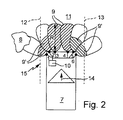
図2によれば、本発明による装置15は、自動車7が直進走行しているときの作動状態を示している。制御ユニット10は、自動車7がこれから通過し、2つの側方の境界12及び13の間の走行方向で自動車7の前方に位置する運転経路11を計算する。制御ユニット10は、ここでは2つの境界12及び13の関数として個別の距離センサ1〜6の検出領域9の範囲Rを制御し、距離センサ3及び4とそれらの検出領域9は、運転経路11内に完全に位置し、それらが最大範囲Rmaxで動作するように制御ユニット10によって作動されるが、距離センサ1、2及び5、6は、それらの検出領域9’が実質的に運転経路11内に位置し、側方の境界12及び13によってその範囲が制限されるように制御ユニット10によって作動される。
According to FIG. 2, the
運転経路11外部に位置する示された障害物8は、ゆえに、図1に反して、距離センサ1で検出されない。あるいは、上述のように、運転経路11外部に位置する障害物8が検出されるが、制御ユニット10によって無関係な物体8として分類され、遮断される。
The
図3によれば、作動状態にある本発明による装置15が、コーナリング時の状況を示している。ここでは、2つの距離センサ2及び3は、それらの最大範囲Rmaxにあるが、距離センサ1、4、5及び6は、それらの範囲R’で制限されている。制御ユニット10はここで、静的及び動的車両データを用いて、特にかじ取り角を基準にしたコーナリング時に自動車7がこれから通過する運転経路11を計算し、範囲R’を運転経路11の側方の境界12及び13に適合させる。運転経路11の外部に位置する物体又は障害物8は、図3による距離センサ4の低減した範囲R’によって検出又は記録されない。それに反して、自動車7がこれから通過する運転経路11に位置する関係のある物体8’は、距離センサ2によって検出される。この物体は適切な識別方法で適切に処理される。
According to FIG. 3, the
制御ユニット10は、ここでは自動車7のブレーキ装置(図示せず)に接続され、制御ユニット10によって発生される制御信号を用いて、自動車7の自動制動を行う。自動制動により、障害物8’との自動車7の衝突が回避できるので、走行安全性が増加する。
Here, the
距離センサ1〜6は、異なる測定法を有するセンサ、例えば超音波センサ、レーダセンサ又は光学センサとして供されても良く、さらに自動車の前部及び/又は後部に配置されても良い。検出領域9は、例えば、自動車の速度、走行方向14、加速度、かじ取り角の変化、センサ関数又は測定方法のようなその時々の車両データの関数として制御ユニット10によって動的に算出して設定される。
The
要約すると、本発明の実質的な特徴は以下のように位置づけられる:
本発明は、制御ユニット10が、静的及び動的車両データを使用して、自動車7がこれから通過する運転経路11を計算でき、運転経路11内に位置する障害物8’と運転経路11の外部に位置する無関係な障害物8とを区別することができるように、車両7と障害物8、8’との間の距離Aを検出する装置15の前記制御ユニット10が設計される。
In summary, the substantial features of the present invention are positioned as follows:
In the present invention, the
運転経路11の計算をすることによって、関係のある及び無関係な物体又は障害物8及び8’間の正確な区別を確実にでき、その結果、走行安全性を改良できる。
By calculating the driving
検出領域が完全に運転経路11内に位置する距離センサ1〜6に関しては、それらが最大範囲Rmaxで動作するように制御ユニット10によって作動される。このことはこの領域に位置する障害物8’が早期に検出されるという利点を有する。
For the
さらに、制御ユニット10は、自動車7のブレーキ装置に接続され、自動車7を自動的に制動させるように設計できる。距離センサ1〜6が、運転経路11内に位置する関係しそうな障害物8’を検出した場合、この信号はに送られ、自動的に自動車7が制動させることにより衝突の危険性が低減される。
Furthermore, the
距離センサ1〜6は、自動車の前部及び/又は後部に任意に配置しても良い。 You may arrange | position the distance sensors 1-6 arbitrarily in the front part and / or rear part of a motor vehicle.
Claims (16)
− 前記制御ユニット(10)が、静的及び動的車両データを使用して、前記自動車(7)がこれから通過する、運転経路(11)を計算し、
− 前記制御ユニット(10)が、前記運転経路(11)内に位置する障害物(8’)と前記運転経路(11)の外部に位置する無関係な障害物(8)とを区別することを特徴とする装置(15)。 In the device (15) for detecting the distance (A) between the vehicle (7) and the obstacle (8, 8 ′), comprising a distance sensor (1-6) and a control unit (10),
The control unit (10) uses static and dynamic vehicle data to calculate the driving path (11) from which the car (7) will pass;
The control unit (10) distinguishes between an obstacle (8 ') located in the driving path (11) and an irrelevant obstacle (8) located outside the driving path (11); Featured device (15).
− 前記制御ユニット(10)が前記距離センサ(1〜6)の前記検出領域(9)の範囲(R)を前記運転経路(11)の側方の境界(12、13)に適合させることを特徴とする請求項1に記載の装置。 The distance sensors (1-6) each have a variable detection area (9);
The control unit (10) adapts the range (R) of the detection area (9) of the distance sensors (1-6) to the lateral boundaries (12, 13) of the driving path (11); The device according to claim 1, wherein
− 前記制御ユニット(10)が、静的及び動的車両データを使用して、前記自動車(7)がこれから通過する運転経路(11)を計算し、
− 前記制御ユニット(10)が、前記運動経路(11)内の関係のある障害物(8’)を前記運転経路(11)の外部に位置する無関係な障害物(8)から区別することを特徴とする方法。 In a method for detecting a distance (A) between an automobile (7) and an obstacle (8, 8 ′) having a distance sensor (1-6) and a control unit (10),
The control unit (10) uses static and dynamic vehicle data to calculate the driving path (11) from which the car (7) will pass;
The control unit (10) distinguishes relevant obstacles (8 ′) in the movement path (11) from irrelevant obstacles (8) located outside the driving path (11); Feature method.
− 前記制御ユニット(10)が前記センサ(1〜6)の検出領域(9)の範囲(R)を前記運転経路(11)の側方の境界(12、13)に適合されることを特徴とする請求項10に記載の方法。 The distance sensors (1-6) each have a variable detection area (9);
The control unit (10) is adapted to the range (R) of the detection area (9) of the sensors (1-6) to the lateral boundaries (12, 13) of the driving path (11); The method according to claim 10.
Applications Claiming Priority (2)
| Application Number | Priority Date | Filing Date | Title |
|---|---|---|---|
| DE10341128A DE10341128A1 (en) | 2003-09-06 | 2003-09-06 | Device and method for detecting a current distance of a motor vehicle from an obstacle |
| PCT/EP2004/009382 WO2005023613A1 (en) | 2003-09-06 | 2004-08-21 | Device and method for detecting the momentary distance of a motor vehicle to an obstacle |
Publications (1)
| Publication Number | Publication Date |
|---|---|
| JP2007504543A true JP2007504543A (en) | 2007-03-01 |
Family
ID=34223406
Family Applications (1)
| Application Number | Title | Priority Date | Filing Date |
|---|---|---|---|
| JP2006525068A Abandoned JP2007504543A (en) | 2003-09-06 | 2004-08-21 | Apparatus and method for detecting distance to obstacle in automobile |
Country Status (5)
| Country | Link |
|---|---|
| US (1) | US20070273490A1 (en) |
| EP (1) | EP1660362B1 (en) |
| JP (1) | JP2007504543A (en) |
| DE (2) | DE10341128A1 (en) |
| WO (1) | WO2005023613A1 (en) |
Families Citing this family (30)
| Publication number | Priority date | Publication date | Assignee | Title |
|---|---|---|---|---|
| US7411542B2 (en) * | 2005-02-10 | 2008-08-12 | Automotive Systems Laboratory, Inc. | Automotive radar system with guard beam |
| DE102005024492A1 (en) * | 2005-05-27 | 2006-11-30 | Daimlerchrysler Ag | Parking assistance for a motor vehicle |
| US7324407B2 (en) * | 2005-07-08 | 2008-01-29 | Valeo Switches And Detection Systems | Prevention of reporting unwanted signals by the filtering of sensor data |
| DE102005039525A1 (en) * | 2005-08-18 | 2007-02-22 | Daimlerchrysler Ag | Method for determining a driving route within which a vehicle is likely to travel |
| JP5016889B2 (en) * | 2006-10-11 | 2012-09-05 | 日立オートモティブシステムズ株式会社 | Preventive safety device |
| US7567168B2 (en) * | 2006-10-24 | 2009-07-28 | Shih-Hsiung Li | Car reversal radar that automatically modifies the sensor scanning range and method of the same |
| DE102006057751A1 (en) * | 2006-12-07 | 2008-06-12 | Siemens Ag | Method for collision avoidance of vehicles with objects |
| JP4613906B2 (en) * | 2006-12-14 | 2011-01-19 | トヨタ自動車株式会社 | Vehicle periphery monitoring device |
| US7830243B2 (en) * | 2007-02-02 | 2010-11-09 | Chrysler Group Llc | Dual mode vehicle blind spot system |
| DE102007036787A1 (en) | 2007-08-03 | 2009-02-05 | Robert Bosch Gmbh | Distance controller with automatic stop function |
| JP2009198402A (en) * | 2008-02-22 | 2009-09-03 | Toyota Motor Corp | Impact detection device |
| DE102008011228A1 (en) | 2008-02-26 | 2009-08-27 | Robert Bosch Gmbh | Method for assisting a user of a vehicle, control device for a driver assistance system of a vehicle and vehicle having such a control device |
| DE102008060684B4 (en) | 2008-03-28 | 2019-05-23 | Volkswagen Ag | Method and device for automatic parking of a motor vehicle |
| FR2941537B1 (en) * | 2009-01-29 | 2016-02-05 | Valeo Vision Sas | METHOD FOR MONITORING THE ENVIRONMENT OF A MOTOR VEHICLE |
| DE102009047066A1 (en) * | 2009-11-24 | 2011-05-26 | Robert Bosch Gmbh | A method for warning of an object in the vicinity of a vehicle and driving assistant system |
| ATE545045T1 (en) | 2009-12-17 | 2012-02-15 | Sick Ag | OPTOELECTRONIC SENSOR |
| DE102010023164A1 (en) | 2010-06-09 | 2011-12-15 | Valeo Schalter Und Sensoren Gmbh | Method for warning presence of pillar in environment to rider of motor car, involves computing path length of prospective track of motor car by driver assistance system, and accounting path length while checking satisfied warning criterion |
| WO2012045323A1 (en) | 2010-10-07 | 2012-04-12 | Connaught Electronics Ltd. | Method and driver assistance system for warning a driver of a motor vehicle of the presence of an obstacle in an environment of the motor vehicle |
| WO2012090114A1 (en) * | 2010-12-26 | 2012-07-05 | Yissum Research Development Company Of The Hebrew University Of Jerusalem Ltd. | Infra red based devices for guiding blind and visually impaired persons |
| US8872641B2 (en) | 2011-05-27 | 2014-10-28 | Headup Systems | Premises-based wireless alert system for automotive tall cargo |
| CN103826929B (en) * | 2011-09-22 | 2016-08-17 | 日产自动车株式会社 | Controller of vehicle |
| KR101316501B1 (en) * | 2011-10-14 | 2013-10-10 | 현대자동차주식회사 | Parking area detection system and method thereof using mesh space analysis |
| EP2816539B1 (en) * | 2012-02-14 | 2018-07-11 | Nissan Motor Co., Ltd. | Travel control device and travel control method |
| JP6123133B2 (en) * | 2013-03-04 | 2017-05-10 | パナソニックIpマネジメント株式会社 | Obstacle detection device for vehicle and obstacle detection system for vehicle |
| DE202013006676U1 (en) * | 2013-07-25 | 2014-10-28 | GM Global Technology Operations LLC (n. d. Ges. d. Staates Delaware) | System for warning of a possible collision of a motor vehicle with an object |
| DE102013217486A1 (en) * | 2013-09-03 | 2015-03-05 | Conti Temic Microelectronic Gmbh | Method for representing an environment of a vehicle in an occupancy grid |
| JP6413240B2 (en) * | 2014-01-08 | 2018-10-31 | 株式会社デンソー | Vehicle control device and vehicle |
| US9983300B2 (en) * | 2014-10-17 | 2018-05-29 | Qualcomm Incorporated | Systems, methods, and apparatus for living object protection in wireless power transfer applications |
| DE102015220643A1 (en) * | 2015-10-22 | 2017-04-27 | Robert Bosch Gmbh | Method and device for reducing a collision risk of a collision of a motor vehicle with an object |
| DE102020102513B4 (en) * | 2020-01-31 | 2022-07-07 | Eisenmann Gmbh | Transport system for transporting workpieces and method for operating such a transport system |
Family Cites Families (15)
| Publication number | Priority date | Publication date | Assignee | Title |
|---|---|---|---|---|
| DE3830790A1 (en) * | 1988-09-09 | 1990-03-15 | Freund Eckhard | METHOD AND DEVICE FOR AUTOMATIC COLLISION AVOIDANCE FOR AUTOMATICALLY DRIVABLE VEHICLES |
| US5479173A (en) * | 1993-03-08 | 1995-12-26 | Mazda Motor Corporation | Obstacle sensing apparatus for vehicles |
| DE4317960A1 (en) * | 1993-05-28 | 1995-01-12 | Bayerische Motoren Werke Ag | Method for avoiding a collision of a motor vehicle |
| DE4333357A1 (en) * | 1993-09-30 | 1995-04-06 | Bosch Gmbh Robert | Parking aid with wheel sensor |
| JP3522317B2 (en) * | 1993-12-27 | 2004-04-26 | 富士重工業株式会社 | Travel guide device for vehicles |
| US5745870A (en) * | 1994-09-14 | 1998-04-28 | Mazda Motor Corporation | Traveling-path prediction apparatus and method for vehicles |
| DE19537129A1 (en) * | 1994-10-05 | 1996-04-11 | Mazda Motor | Obstacle detecting system for cars |
| DE19507957C1 (en) * | 1995-03-07 | 1996-09-12 | Daimler Benz Ag | Vehicle with optical scanning device for a side lane area |
| DE19645339B4 (en) * | 1996-11-04 | 2010-05-06 | Valeo Schalter Und Sensoren Gmbh | Method for measuring the distance dependent on the vehicle data from a vehicle |
| JP2000075028A (en) * | 1998-08-27 | 2000-03-14 | Toyota Motor Corp | Mobile dbf radar |
| DE19934670B4 (en) * | 1999-05-26 | 2004-07-08 | Robert Bosch Gmbh | Object detection system |
| US6150932A (en) * | 1999-10-04 | 2000-11-21 | General Motors Corporation | Vehicle operator alert process |
| DE10149146A1 (en) * | 2001-10-05 | 2003-04-17 | Bosch Gmbh Robert | Speed regulator with distance regulating function for motor vehicle, has monitoring module for detecting situation with danger of objects not detected by location system being in immediate vicinity |
| DE10160189B4 (en) * | 2001-12-07 | 2019-06-06 | Bayerische Motoren Werke Aktiengesellschaft | ACC lane prediction width adaptation depending on navigation system data and object data |
| WO2003064215A1 (en) * | 2002-01-28 | 2003-08-07 | Matsushita Electric Works, Ltd. | Obstacle detecting/alarming system for vehicle |
-
2003
- 2003-09-06 DE DE10341128A patent/DE10341128A1/en not_active Withdrawn
-
2004
- 2004-08-21 US US10/570,800 patent/US20070273490A1/en not_active Abandoned
- 2004-08-21 EP EP04764364A patent/EP1660362B1/en not_active Expired - Fee Related
- 2004-08-21 WO PCT/EP2004/009382 patent/WO2005023613A1/en active IP Right Grant
- 2004-08-21 JP JP2006525068A patent/JP2007504543A/en not_active Abandoned
- 2004-08-21 DE DE502004006940T patent/DE502004006940D1/en not_active Expired - Fee Related
Also Published As
| Publication number | Publication date |
|---|---|
| WO2005023613A1 (en) | 2005-03-17 |
| DE10341128A1 (en) | 2005-03-31 |
| EP1660362A1 (en) | 2006-05-31 |
| DE502004006940D1 (en) | 2008-06-05 |
| US20070273490A1 (en) | 2007-11-29 |
| EP1660362B1 (en) | 2008-04-23 |
Similar Documents
| Publication | Publication Date | Title |
|---|---|---|
| JP2007504543A (en) | Apparatus and method for detecting distance to obstacle in automobile | |
| KR101991602B1 (en) | Method for detecting an object in an opening region of a door of a motor vehicle, driver assistance system, and motor vehicle | |
| US5699040A (en) | Vehicle collision preventing system | |
| US20170299717A1 (en) | Method for detecting at least one object in a surrounding area of a motor vehicle, driver assistance system and motor vehicle | |
| EP3039450B1 (en) | In-vehicle control device | |
| JP3645988B2 (en) | Vehicle obstacle detection device | |
| JP5694669B2 (en) | How to monitor the surrounding environment of a car | |
| WO2016038773A1 (en) | Collision prevention device | |
| US8633832B2 (en) | Obstacle detection apparatus for vehicle | |
| CN104875729B (en) | Automatic rear brake | |
| US11615708B2 (en) | Collision avoidance control apparatus | |
| KR101868088B1 (en) | Apparatus and method for collision avoiding using ultrasonic sensor | |
| JP6574407B2 (en) | Vehicle control apparatus and vehicle control method | |
| US11001255B2 (en) | Driving assistance apparatus and driving assistance method | |
| JP3923200B2 (en) | Vehicle obstacle detection method | |
| JP3913911B2 (en) | Vehicle obstacle detection device | |
| CN112292301A (en) | Method and driving assistance system for avoiding collision of vehicle with obstacle | |
| JP4956043B2 (en) | Vehicle object detection device | |
| KR20170071272A (en) | Rear collision warning control method and apparatus | |
| US20050060117A1 (en) | Method and device for determination of the distance of a sensor device to an object | |
| CN113573965A (en) | Method for determining the risk of accidents caused by moisture for a vehicle | |
| JP3148776B2 (en) | Road detector for vehicles | |
| JP3230832B2 (en) | Vehicle safety equipment | |
| JP4980969B2 (en) | Vehicle object detection device | |
| JP2859928B2 (en) | Rear monitoring device for vehicles |
Legal Events
| Date | Code | Title | Description |
|---|---|---|---|
| A621 | Written request for application examination |
Free format text: JAPANESE INTERMEDIATE CODE: A621 Effective date: 20070515 |
|
| RD02 | Notification of acceptance of power of attorney |
Free format text: JAPANESE INTERMEDIATE CODE: A7422 Effective date: 20070710 |
|
| RD04 | Notification of resignation of power of attorney |
Free format text: JAPANESE INTERMEDIATE CODE: A7424 Effective date: 20070720 |
|
| RD04 | Notification of resignation of power of attorney |
Free format text: JAPANESE INTERMEDIATE CODE: A7424 Effective date: 20070710 |
|
| A762 | Written abandonment of application |
Free format text: JAPANESE INTERMEDIATE CODE: A762 Effective date: 20080306 |