JP2007504392A - Liquid fuel additive supply pump - Google Patents
Liquid fuel additive supply pump Download PDFInfo
- Publication number
- JP2007504392A JP2007504392A JP2006525149A JP2006525149A JP2007504392A JP 2007504392 A JP2007504392 A JP 2007504392A JP 2006525149 A JP2006525149 A JP 2006525149A JP 2006525149 A JP2006525149 A JP 2006525149A JP 2007504392 A JP2007504392 A JP 2007504392A
- Authority
- JP
- Japan
- Prior art keywords
- pump
- piston
- supply pump
- additive
- supply
- Prior art date
- Legal status (The legal status is an assumption and is not a legal conclusion. Google has not performed a legal analysis and makes no representation as to the accuracy of the status listed.)
- Pending
Links
- 239000007788 liquid Substances 0.000 title claims abstract description 14
- 239000002816 fuel additive Substances 0.000 title claims description 3
- 239000000654 additive Substances 0.000 claims abstract description 35
- 230000000996 additive effect Effects 0.000 claims abstract description 30
- 239000000446 fuel Substances 0.000 claims abstract description 27
- 239000007787 solid Substances 0.000 claims description 2
- 239000000295 fuel oil Substances 0.000 claims 1
- 239000002828 fuel tank Substances 0.000 description 10
- 239000002283 diesel fuel Substances 0.000 description 6
- 239000000463 material Substances 0.000 description 5
- 239000011800 void material Substances 0.000 description 4
- 239000012528 membrane Substances 0.000 description 3
- 239000002184 metal Substances 0.000 description 3
- 229910052751 metal Inorganic materials 0.000 description 3
- 150000003839 salts Chemical class 0.000 description 3
- 238000005336 cracking Methods 0.000 description 2
- 238000006073 displacement reaction Methods 0.000 description 2
- 238000002347 injection Methods 0.000 description 2
- 239000007924 injection Substances 0.000 description 2
- 239000004033 plastic Substances 0.000 description 2
- 229920001748 polybutylene Polymers 0.000 description 2
- 229920001343 polytetrafluoroethylene Polymers 0.000 description 2
- 239000004810 polytetrafluoroethylene Substances 0.000 description 2
- QGZKDVFQNNGYKY-UHFFFAOYSA-N Ammonia Chemical compound N QGZKDVFQNNGYKY-UHFFFAOYSA-N 0.000 description 1
- 239000004215 Carbon black (E152) Substances 0.000 description 1
- BVKZGUZCCUSVTD-UHFFFAOYSA-L Carbonate Chemical compound [O-]C([O-])=O BVKZGUZCCUSVTD-UHFFFAOYSA-L 0.000 description 1
- 229910052684 Cerium Inorganic materials 0.000 description 1
- XEEYBQQBJWHFJM-UHFFFAOYSA-N Iron Chemical compound [Fe] XEEYBQQBJWHFJM-UHFFFAOYSA-N 0.000 description 1
- 239000004809 Teflon Substances 0.000 description 1
- 229920006362 Teflon® Polymers 0.000 description 1
- XSQUKJJJFZCRTK-UHFFFAOYSA-N Urea Chemical compound NC(N)=O XSQUKJJJFZCRTK-UHFFFAOYSA-N 0.000 description 1
- 239000004202 carbamide Substances 0.000 description 1
- 125000004432 carbon atom Chemical group C* 0.000 description 1
- GWXLDORMOJMVQZ-UHFFFAOYSA-N cerium Chemical compound [Ce] GWXLDORMOJMVQZ-UHFFFAOYSA-N 0.000 description 1
- 238000002485 combustion reaction Methods 0.000 description 1
- 238000010276 construction Methods 0.000 description 1
- 238000007599 discharging Methods 0.000 description 1
- 229920001971 elastomer Polymers 0.000 description 1
- 239000000806 elastomer Substances 0.000 description 1
- 239000003344 environmental pollutant Substances 0.000 description 1
- 239000012530 fluid Substances 0.000 description 1
- 229930195733 hydrocarbon Natural products 0.000 description 1
- 150000002430 hydrocarbons Chemical class 0.000 description 1
- 238000009434 installation Methods 0.000 description 1
- 239000002245 particle Substances 0.000 description 1
- 231100000719 pollutant Toxicity 0.000 description 1
- -1 polytetrafluoroethylene Polymers 0.000 description 1
- 230000002787 reinforcement Effects 0.000 description 1
- 229920002379 silicone rubber Polymers 0.000 description 1
- 239000000243 solution Substances 0.000 description 1
- 239000002904 solvent Substances 0.000 description 1
Images

Classifications
-
- F—MECHANICAL ENGINEERING; LIGHTING; HEATING; WEAPONS; BLASTING
- F02—COMBUSTION ENGINES; HOT-GAS OR COMBUSTION-PRODUCT ENGINE PLANTS
- F02M—SUPPLYING COMBUSTION ENGINES IN GENERAL WITH COMBUSTIBLE MIXTURES OR CONSTITUENTS THEREOF
- F02M25/00—Engine-pertinent apparatus for adding non-fuel substances or small quantities of secondary fuel to combustion-air, main fuel or fuel-air mixture
-
- F—MECHANICAL ENGINEERING; LIGHTING; HEATING; WEAPONS; BLASTING
- F04—POSITIVE - DISPLACEMENT MACHINES FOR LIQUIDS; PUMPS FOR LIQUIDS OR ELASTIC FLUIDS
- F04B—POSITIVE-DISPLACEMENT MACHINES FOR LIQUIDS; PUMPS
- F04B13/00—Pumps specially modified to deliver fixed or variable measured quantities
-
- F—MECHANICAL ENGINEERING; LIGHTING; HEATING; WEAPONS; BLASTING
- F04—POSITIVE - DISPLACEMENT MACHINES FOR LIQUIDS; PUMPS FOR LIQUIDS OR ELASTIC FLUIDS
- F04B—POSITIVE-DISPLACEMENT MACHINES FOR LIQUIDS; PUMPS
- F04B17/00—Pumps characterised by combination with, or adaptation to, specific driving engines or motors
- F04B17/03—Pumps characterised by combination with, or adaptation to, specific driving engines or motors driven by electric motors
Landscapes
- Engineering & Computer Science (AREA)
- Mechanical Engineering (AREA)
- General Engineering & Computer Science (AREA)
- Chemical & Material Sciences (AREA)
- Combustion & Propulsion (AREA)
- Details Of Reciprocating Pumps (AREA)
- Reciprocating Pumps (AREA)
- Infusion, Injection, And Reservoir Apparatuses (AREA)
- Feeding And Controlling Fuel (AREA)
- Jet Pumps And Other Pumps (AREA)
Abstract
重質燃料エンジンの燃料中の液体添加剤のための供給ポンプであって、このポンプは、ピストン(3)、シリンダ(1)及びピストン(3)をシリンダ(1)内で軸方向に動かすアクチュエータ(7)を有し、このアクチュエータ(7)は、高分解能リニアアクチュエータである。
【選択図】図4A feed pump for a liquid additive in the fuel of a heavy fuel engine, the pump moving the piston (3), the cylinder (1) and the piston (3) axially within the cylinder (1) This actuator (7) is a high resolution linear actuator.
[Selection] Figure 4
Description
本発明は、車両のエンジンに、このエンジンの排気ガス中に、又は重質燃料(即ち、10個以上の炭素原子を有する燃料、典型的には、ディーゼル油)を用いるエンジンでは、この燃料中に直接、好ましくは燃料タンク内に供給される液体添加物(場合によっては、非常に濃縮されている)のための供給ポンプに関する。 The present invention relates to a vehicle engine, in the exhaust gas of the engine, or in an engine using a heavy fuel (ie, a fuel having 10 or more carbon atoms, typically diesel oil). A feed pump for liquid additives (possibly highly concentrated) fed directly into the fuel tank.
尿素、液体アンモニア及びカーボネートのような添加物の目的は、エンジンによるNOx及びCOのような汚染物の放出を低減することであり、その一方で、重質燃料エンジンの排気系統のフィルタに付着保持された粒子の燃焼温度を下げるために金属塩(炭化水素溶剤中に溶けている鉄(Fe)又はセリウム(Ce)の塩のような金属塩)が一般に用いられている。 The purpose of additives such as urea, liquid ammonia and carbonate is to reduce the emission of pollutants such as NOx and CO by the engine while retaining it on the filter of heavy fuel engine exhaust systems Metal salts (metal salts such as iron (Fe) or cerium (Ce) salts dissolved in hydrocarbon solvents) are commonly used to lower the combustion temperature of the formed particles.
既存のシステムは、添加剤としての液体を注入しなければならない場所(かかる場所は、大抵の場合、エンジン内、排気ガス中、燃料タンク内、エンジンの燃料供給管又は燃料戻り管内であり、これを本願では「エンジン回路」と総称する)にかかる液体添加剤を供給するための従来型ピストンポンプを用いる。このピストンポンプは、定容積ポンプであり、この場合、ポンプは、1行程当たり一定のあらかじめ設定された量を供給する(一般に、ピストンが動くシリンダの容積で決まる)。 Existing systems are where the additive liquid must be injected (which is often in the engine, in the exhaust gas, in the fuel tank, in the engine fuel supply line or in the fuel return line). In this application, a conventional piston pump for supplying a liquid additive is used. The piston pump is a constant volume pump, where the pump supplies a constant preset amount per stroke (generally determined by the volume of the cylinder in which the piston moves).
米国特許出願第2003/0136355号明細書は、燃料取出しモジュール内に組み込まれた計量ポンプによって燃料タンク内部に燃料添加剤を供給するシステムを開示している。この計量ポンプは、一定量の添加剤を各ポンプサイクルで送り出す容量形ポンプ(ピストンポンプ)である。必要な全供給分量は、ポンプを所要回数のサイクル、作動させることによって送り出される。欠点は次の通りである。 U.S. Patent Application No. 2003/0136355 discloses a system for supplying a fuel additive into a fuel tank by a metering pump incorporated in a fuel removal module. This metering pump is a displacement pump (piston pump) that delivers a certain amount of additive in each pump cycle. The total supply required is delivered by operating the pump for the required number of cycles. The disadvantages are as follows.
最適結果を得るために、正確な供給量が必要であるにもかかわらず、ピストン容積と関連した誤差が、行程の回数にわたり蓄積されること。
過剰供給の恐れがある(シリンダ容積分を部分的に送りだすことができないため)ことであり、これは、添加剤の価格を考慮すると費用が高くつく。
作動に用いられるソレノイド弁は、一般に騒音が大きいことである。
The error associated with piston volume accumulates over the number of strokes, despite the need for accurate feed rates to obtain optimal results.
There is a risk of oversupply (because the cylinder volume cannot be partially delivered), which is costly considering the price of the additive.
The solenoid valve used for operation is generally noisy.
本発明の目的は、これら欠点のうちの少なくとも幾つかを解決することにある。 The object of the present invention is to overcome at least some of these drawbacks.
本発明は、主として、上述の定容積ポンプに代えて可変容積ポンプ、即ち、必ずしもあらかじめ設定されているわけではない量を送り出すことができるポンプを用いることにある。 The present invention mainly uses a variable volume pump, that is, a pump capable of delivering an amount not necessarily set in advance, instead of the above-described constant volume pump.
したがって、本発明は、重質燃料エンジンの燃料中の液体添加剤のための供給ポンプであって、前記ポンプは、ピストン、シリンダ及びピストンをシリンダ内で軸方向に動かすアクチュエータを有し、前記アクチュエータは、高分解能リニアアクチュエータである、供給ポンプに関する。 Accordingly, the present invention is a supply pump for a liquid additive in the fuel of a heavy fuel engine, the pump comprising a piston, a cylinder and an actuator for moving the piston axially within the cylinder, the actuator Relates to a feed pump, which is a high resolution linear actuator.
かかるアクチュエータの利用により、本発明のポンプは、所要量を送り出すことができ且つセルフプライミング式の可変容積ポンプである。 By using such an actuator, the pump of the present invention is a self-priming variable volume pump that can deliver a required amount.
本発明のポンプは一般に、ピストンの他に、シリンダ(ハウジング)及びアクチュエータ、並びに添加剤をそれぞれ吸入し、排出する少なくとも1つの入口逆止弁及び少なくとも1つの出口逆止弁を備えたマニホルドを有する。かかる弁は、任意形式のものであってよく、これら弁は、受動式の弁(即ち、自動的に機能を発揮する弁、即ち、これら弁を通る液体の流れ以外のどの手段によっても作動されることはない弁)であって一方弁(即ち、かかる弁を通る液体の1つの流れ方向のみを可能にする弁)であるのが好ましい。 In addition to the piston, the pump of the present invention generally has a cylinder (housing) and actuator, and a manifold with at least one inlet check valve and at least one outlet check valve for sucking and discharging additives, respectively. . Such valves may be of any type and are actuated by any means other than passive valves (i.e., valves that perform automatically, i.e., the flow of liquid through the valves). Preferably one-way valve (ie a valve that allows only one flow direction of liquid through such valve).
本発明の可変容積ポンプは、シリンジポンプ、即ち、ピストンが各供給サイクルの終わりに固体面(これは、ポンプのシリンダボアの端部又はマニホルドの内面であるのがよい)に接触するポンプであるのが好ましい。「供給サイクル」という用語は、ポンプの2回の連続した吸入段階の間における動作のシーケンス全体を意味している。したがって、各サイクルの終わりに、シリンジは、端停止部に戻り、高い再現性を保証する。さらに、各サイクル後においてポンプ本体内に残っている添加剤の量は、最小限に抑えられ、それにより、温度変化中に生じる場合のある添加剤からのガス又は上記の漏れの潜在的な恐れが最小限に抑えられる。 The variable volume pump of the present invention is a syringe pump, i.e. a pump whose piston contacts the solid surface at the end of each supply cycle, which may be the end of the cylinder bore of the pump or the inner surface of the manifold. Is preferred. The term “feed cycle” means the entire sequence of operation between two successive suction phases of the pump. Thus, at the end of each cycle, the syringe returns to the end stop to ensure high reproducibility. In addition, the amount of additive remaining in the pump body after each cycle is minimized, thereby the potential risk of gas or additive leakage from the additive that may occur during temperature changes. Is minimized.
本発明の「高分解能リニアアクチュエータ」は、実際に、直線位置を高い分解能に合わせて制御できるアクチュエータを意味している。「高分解能」という用語は、精度が1mm以下、好ましくは0.1mm以下、より好ましくは50μm以下のものでなければならないことを意味する。本発明に用いられるリニアアクチュエータは好ましくは、ピストンを非常に僅かな増分で動かして1回のステップにつき非常に高い精度を達成し、コントローラによって制御される電気ステップモータを含む。かかるアクチュエータの利点は、例えば、ソレノイドポンプと比較して、そのサイズが小さいこと(コンパクトであること)、その電力消費量が少ないことである。 The “high resolution linear actuator” of the present invention means an actuator that can actually control the linear position according to high resolution. The term “high resolution” means that the accuracy should be 1 mm or less, preferably 0.1 mm or less, more preferably 50 μm or less. The linear actuator used in the present invention preferably includes an electric stepper motor that is controlled by a controller that moves the piston in very small increments to achieve very high accuracy per step. The advantage of such an actuator is, for example, that its size is small (compact) and its power consumption is small compared to a solenoid pump.
最も好ましくは、リニアアクチュエータは、減速歯車装置を介して回転電気モータにより駆動される。利点は次のとおりである。 Most preferably, the linear actuator is driven by a rotating electric motor via a reduction gear device. The advantages are as follows.
減速歯車装置は、高い精度の添加剤の量的供給に対応した高い精度の直線位置をもたらし、また、騒音が大きくないこと。
減速歯車装置は、回転電気モータが付勢されていないときにピストン移動への高い耐性をもたらし、ピストンがシールを入口孔及び出口孔に密着維持するようにすること。
The reduction gear unit provides a highly accurate linear position corresponding to the quantitative supply of highly accurate additives and is not loud.
The reduction gear system provides high resistance to piston movement when the rotary electric motor is not energized, so that the piston keeps the seal in close contact with the inlet and outlet holes.
アクチュエータの直線位置を高分解能に合わせて制御する上で考えられる他の手段は、次の通りである。 Other possible means for controlling the linear position of the actuator in accordance with the high resolution are as follows.
(A)クランクであって、クランク端部(ピストン)の直線位置を高い精度に合わせて制御できる(そして、サイクル中の任意の点で逆転させることができる)よう減速歯車装置により駆動されるクランク。
(B)直線電気モータ、例えば圧電モータにより駆動されるリニアアクチュエータ。
クランク(実施形態A)の場合、長尺のクランクを用いてピストンの大きな直線運動を生じさせるのがよい。
(A) A crank that is driven by a reduction gear device so that the linear position of the crank end (piston) can be controlled with high accuracy (and can be reversed at any point in the cycle). .
(B) A linear actuator driven by a linear electric motor, for example, a piezoelectric motor.
In the case of the crank (Embodiment A), it is preferable to generate a large linear motion of the piston using a long crank.
一実施形態によれば、本発明のポンプは、所要最大供給分量(関与する燃料の量を考慮して)に等しい容量を有し、最大供給分量までの量を送り出し又は小出しする。これは、所要添加剤量がポンプの1サイクルだけで送り出されることを意味し、これは、非常に静音設計の解決策であるが、幾分サイズの大きなものである。 According to one embodiment, the pump of the present invention has a capacity equal to the required maximum supply (considering the amount of fuel involved) and delivers or dispenses up to the maximum supply. This means that the amount of additive required is delivered in just one pump cycle, which is a very quiet design solution, but somewhat larger in size.
別の好ましい実施形態によれば、本発明のポンプは、車両のより多くの場所に設置するようにするために容量の減少したものである(即ち、最大供給分量よりも少ない)。ポンプは、1回以上の注入により(即ち、1回以上のポンプサイクルにより)所要量の添加剤を小出しする。 According to another preferred embodiment, the pump of the present invention is of reduced capacity (ie, less than the maximum supply volume) for installation in more locations of the vehicle. The pump dispenses the required amount of additive by one or more injections (ie, by one or more pump cycles).
この実施形態では、ピストンは、マニホルドに正確に嵌合して全ての添加剤が繰り返し絞り出されるようになる。これは、ポンプが吸入時に正確でありさえすればよいことを意味する。 In this embodiment, the piston fits precisely into the manifold so that all additives are squeezed out repeatedly. This means that the pump only needs to be accurate when inhaling.
本発明のポンプは一般に、ピストンとシリンダとの間の密封状態を保証するシールを有する。このシールは、シールは、ピストンのヘッドに半径方向に配置され、ピストンと一緒にシリンダ内を摺動する摺動シールであってもよい。しかしながら、好ましくは、このシールは、少なくとも一部がピストンに取り付けられ、ピストンと一緒に動く低摩擦皿形又はダイヤフラムシールである。かかるシールの利点は、次の通りである。 The pump of the present invention generally has a seal that ensures a tight seal between the piston and the cylinder. The seal may be a sliding seal that is radially disposed on the piston head and slides in the cylinder with the piston. Preferably, however, the seal is a low friction dish or diaphragm seal that is at least partially attached to the piston and moves with the piston. The advantages of such a seal are as follows.
ピストンを重要な非使用期間後に最初に動かしたとき、モータに加わる力が非常に低く、モータのスリップが無く、ポンプの精度が確保されること。
添加剤の層がシリンジの内面上に残って乾き、そして剥落することが無く、潜在的な電気的短絡が生じたり、機構がつかえて動かなくなるようなことが無いこと。
漏れが決して生じず、その結果、精度が保たれること。
When the piston is moved for the first time after an important period of non-use, the force applied to the motor is very low, there is no motor slip, and the accuracy of the pump is ensured.
The additive layer remains on the inner surface of the syringe, does not dry out, and does not peel off, causing a potential electrical short circuit or causing the mechanism to become stuck.
Leakage never occurs, and as a result, accuracy is maintained.
ダイヤフラムシールの別の利点は、このダイヤフラムシールが、半径方向の運動に順応することができ、固定クランク式リニアアクチュエータ(上述の実施形態A)との適合性が極めて高いことである。 Another advantage of the diaphragm seal is that it can adapt to radial motion and is very compatible with the fixed crank linear actuator (embodiment A above).
その点に関し、本発明の主目的が高分解能リニアアクチュエータにより駆動されるポンプを提供することにあるが、上述のダイヤフラムシールの全ての利点も又、かかるアクチュエータが設けられていないポンプの場合にも存在するということに注目することは、価値がある。かかるポンプは米国特許第4,874,299号明細書で知られているが、この米国特許明細書に記載されたポンプは、往復動ポンプであり、即ち、定容積ポンプであって、可変容積ポンプではない。したがって、リニアアクチュエータが設けられていることを除き、上述したようなダイヤフラム付き可変容量ポンプは、本発明のもう1つの特徴である。ただし、ディーゼル添加物を供給するためにはリニアアクチュエータを選択することが好ましい。 In that regard, the main object of the present invention is to provide a pump driven by a high-resolution linear actuator, but all the advantages of the diaphragm seal described above are also present in the case of a pump without such an actuator. It is worth noting that it exists. Such a pump is known from U.S. Pat. No. 4,874,299, which is a reciprocating pump, i.e. a constant volume pump, having a variable volume. It is not a pump. Therefore, the variable displacement pump with a diaphragm as described above is another feature of the present invention except that a linear actuator is provided. However, it is preferable to select a linear actuator to supply the diesel additive.
本発明のポンプの構成材料は、供給される添加剤に対する耐性があるよう選択される。一般に、ピストン及びシリンダは、プラスチック(例えば、PBT(ポリブチレン)のようなプラスチック)であり、シールは、エラストマー、最も好ましくは、弗素化シリコーンエラストマーである。皿形シールの場合、その形状及び材料は、ポンプが「吸入」するときにシールの延伸を阻止する上で非常に重要である。シールのプロフィールは好ましくは、力(及びそれ故シールの延伸)が吸入中最小限に抑えられるよう設計される。他の手段としては、シールの材料補強をおこなうこと及び延伸を阻止する(そして、材料の適合性を高める)PTFE(ポリテトラフルオロエチレンであり、一般に「テフロン」と呼ばれている)ような材料でシールを覆うことが挙げられる。 The material of construction of the pump of the present invention is selected to be resistant to the additive supplied. Generally, the piston and cylinder are plastic (eg, plastic such as PBT (polybutylene)) and the seal is an elastomer, most preferably a fluorinated silicone elastomer. In the case of a dish-shaped seal, its shape and material are very important in preventing the seal from stretching when the pump “inhales”. The seal profile is preferably designed so that the force (and hence the stretch of the seal) is minimized during inhalation. Other means are materials such as PTFE (polytetrafluoroethylene, commonly referred to as “Teflon”) that provide material reinforcement of the seal and prevent stretch (and increase material compatibility) Covering the seal with.
皿形シールを用いた供給ポンプでは、供給される量は、ピストンの運動と正比例関係又は線形関係にあるわけではない。しかしながら、シールの形状は、その現象を最小限に抑えるようになっており、残っている非線形性は、(モータを駆動するコントローラによって)電気的に除かれる。 In a feed pump using a countersunk seal, the amount delivered is not directly proportional or linear with the piston motion. However, the shape of the seal is such that the phenomenon is minimized and the remaining non-linearity is electrically removed (by the controller driving the motor).
本発明の供給ポンプは、重質燃料エンジンの燃料系統又は燃料システムの一部であるのが好ましい。したがって、別の特徴によれば、本発明は、上述した供給ポンプを装備した燃料系統に関する。燃料系統という用語は、燃料の取扱い(ディーゼル油の場合、貯蔵、供給及び戻し)に用いられる全ての要素/装置を意味している。かかるシステムは一般に、少なくとも、燃料タンク、供給管、ガス抜きライン及び燃料供給/戻りライン並びに本発明のフレーム内の添加剤リザーバを有する。 The feed pump of the present invention is preferably part of a heavy fuel engine fuel system or fuel system. Thus, according to another feature, the present invention relates to a fuel system equipped with a supply pump as described above. The term fuel system means all elements / devices used for fuel handling (in the case of diesel oil, storage, supply and return). Such a system generally includes at least a fuel tank, a supply line, a vent line and a fuel supply / return line and an additive reservoir within the frame of the present invention.
この実施形態によれば、ポンプは好ましくは、燃料系統内の以下の場所のうちの1つに配置される。 According to this embodiment, the pump is preferably located at one of the following locations in the fuel system:
a.特に、もしフランス国特許出願第03.13073号明細書に記載されているように添加剤リザーバがここに設けられているなら、供給管領域内。
b.添加剤リザーバと燃料タンクとの間。
c.燃料タンク、燃料タンクの上方又は下方(特に、フランス国特許出願第04.00856号明細書に記載されているように添加剤リザーバが燃料タンクに一体化されている場合(この場合、ポンプは好ましくは、燃料タンクに固定された燃料引き出しモジュールに近接して位置する)。
d.上述の米国特許明細書に記載されている燃料取出しモジュール内。
e.燃料戻しライン(これは、高温燃料をエンジンの注入レールから燃料タンクに戻すライン)の近く又は燃料戻しライン上。
a. In particular, if an additive reservoir is provided here as described in French patent application No. 03.13073, in the supply pipe region.
b. Between additive reservoir and fuel tank.
c. Fuel tank, above or below the fuel tank (especially when the additive reservoir is integrated into the fuel tank as described in French patent application No. 04.00856 (in this case, the pump is preferably Is located close to the fuel drawer module fixed to the fuel tank).
d. In the fuel removal module described in the above-mentioned US patent specification.
e. Near or on the fuel return line (this is the line that returns hot fuel from the injection rail of the engine to the fuel tank).
したがって、共通のポンプ本体の設計を上述したような特注の流体マニホルドを用いることにより多種多様な形態のシステムに組み込むことができる。 Thus, a common pump body design can be incorporated into a wide variety of systems by using a custom fluid manifold as described above.
本発明の供給ポンプのコントローラには、供給すべき添加剤の量又は好ましくは追加した燃料の量を知らせることができる(したがって、プロセッサは、所要供給分量を計算することができるようになっており、即ち、コントローラが使用中、添加剤の濃度及び種類を知ることが必要なだけである)。 The controller of the feed pump of the present invention can be informed of the amount of additive to be fed or preferably the amount of added fuel (thus the processor is able to calculate the required feed rate). That is, it is only necessary for the controller to know the concentration and type of additive during use).
本発明は、図1〜図4に非限定的に示されており、これらの図は、事実、本発明の2つの好ましい実施形態を示している。これらの図において、同一の符号は、同一/類似の要素を示している。 The present invention is illustrated in a non-limiting manner in FIGS. 1-4, which in fact show two preferred embodiments of the present invention. In these figures, the same reference numerals indicate the same / similar elements.
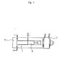
〔図1及び図2の説明:実施形態1〕
これら図は、容量が約8mlの摺動シール付きシリンジポンプを示している。
[Explanation of FIGS. 1 and 2: Embodiment 1]
These drawings show a syringe pump with a sliding seal having a capacity of about 8 ml.
シリンジは、計算された供給分量での比例動作を1回だけ行うピストン(3)によって、マニホルド(6)内に設けられた入口穴(I)と、シール(5)と、一方弁(2)とを通して液体添加剤を吸入する。 The syringe has an inlet hole (I) provided in the manifold (6), a seal (5), and a one-way valve (2) by means of a piston (3) that performs a proportional operation with the calculated supply amount only once. Inhale the liquid additive through.
ピストン(3)は、アクチュエータ(7)の一部であるステップモータ及び減速歯車装置によって動く。ピストン(3)とシリンダ(1)との間には摺動シール(4)が設けられている。 The piston (3) is moved by a step motor and a reduction gear device that are part of the actuator (7). A sliding seal (4) is provided between the piston (3) and the cylinder (1).
液体吸入後、シリンジは、ピストン(3)により、支持体(6)に設けられた出口穴(O)と、シール(5′)と、一方弁(2′)とを通って液体添加剤をディーゼル燃料タンクに送り込む。 After inhaling the liquid, the syringe passes the liquid additive through the outlet hole (O) provided in the support (6), the seal (5 '), and the one-way valve (2') by the piston (3). Feed into diesel fuel tank.
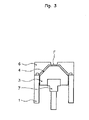
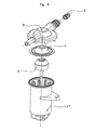
〔図3及び図4の説明:実施形態2〕
これらの図は、容量が約0.5mlの皿形シール付きメンブレン−シリンジポンプを示している。
[Explanation of FIGS. 3 and 4: Embodiment 2]
These figures show a membrane-syringe pump with a dish-shaped seal having a capacity of about 0.5 ml.
その貯蔵/リセット位置が図3に示されている。ピストンは、シール(4)を上方に押してマニホルド(6)、即ち、その端停止部に押し付ける。シール(4)は、その周囲のところでシリンダ(1)とマニホルド(6)との間に固定され(添加剤を通さないシールを形成する)、その平らな頂部(F)を介してピストン(3)に取り付けられている。ピストン(3)が動くと、シールの頂部(F)は、ピストンと一緒に動き、マニホルド(6)とシール(4)との間にボイドが作られる。 Its store / reset position is shown in FIG. The piston pushes the seal (4) upwards against the manifold (6), ie its end stop. The seal (4) is fixed between the cylinder (1) and the manifold (6) at its periphery (to form an additive-free seal), and through its flat top (F) the piston (3 ). As the piston (3) moves, the top (F) of the seal moves with the piston, creating a void between the manifold (6) and the seal (4).
シリンジは、最大、計算された供給分量まで多数回の行程を実施するピストン(3)によって、マニホルド(6)に設けられた入口穴及び一方弁(2)を通って添加剤としての液体を吸入する。 The syringe draws in liquid as an additive through the inlet hole in the manifold (6) and the one-way valve (2) by the piston (3) that performs a number of strokes up to the calculated supply volume. To do.
ピストン(3)は、アクチュエータ(7)の一部であるステップモータ及び減速歯車装置によって動き、このアクチュエータは、この場合、シリンダ(1)と一体に作られている。 The piston (3) is moved by a step motor and a reduction gear device which are part of the actuator (7), which in this case is made in one piece with the cylinder (1).
以下のシーケンスが、ポンプの一サイクルを構成する。 The following sequence constitutes one cycle of the pump.
モータが設定された数のステップについて回転するように、モータをコントローラによって駆動する。ステップの数は、所定の直線移動距離と等価である。
ピストン(3)が動くと、入口弁のクラッキング圧力よりも高くなり、添加剤がマニホルド(6)とシール(4)との間に作られたボイドに流入する。
ピストン(3)は、モータがコントローラにより命令されたステップ数、回転すると停止する。すると、ピストンは方向を変え、出口逆止弁(図示せず)及びディーゼル油タンク逆止弁は、これらの相互クラッキング圧力をいったん超えると、開く。添加剤は、ボイドからディーゼル油タンク内へ流入し、遂にはピストン(3)は、底がマニホルド(6)に突き当たるようになる。
The motor is driven by the controller so that the motor rotates for a set number of steps. The number of steps is equivalent to a predetermined linear movement distance.
As the piston (3) moves, it becomes higher than the cracking pressure of the inlet valve, and the additive flows into the void created between the manifold (6) and the seal (4).
The piston (3) stops when the motor rotates the number of steps commanded by the controller. The piston then changes direction and the outlet check valve (not shown) and the diesel oil tank check valve open once these mutual cracking pressures are exceeded. The additive flows from the void into the diesel oil tank, and finally the piston (3) comes to abut against the manifold (6).
供給した添加剤の量は、マニホルド(6)とシール(4)との間に形成されたボイドの容積で決まる。この量は、ピストン(3)を押し退けたときにシール(4)により形成される回旋部によって決定される。供給は、各サイクル相互間で1または2以上のサイクルで構成され、モータは、リニアアクチュエータをその貯蔵/リセット位置に駆動する。 The amount of additive supplied is determined by the volume of the void formed between the manifold (6) and the seal (4). This amount is determined by the convolution formed by the seal (4) when the piston (3) is pushed away. Supply consists of one or more cycles between each cycle and the motor drives the linear actuator to its store / reset position.
1ステップのポンプ分解後、寸法及び精度は、ステップモータの分解能の関数であり、これは一定であって送られる量とは無関係である。 After one step of pump disassembly, the size and accuracy are a function of the resolution of the stepper motor, which is constant and independent of the amount delivered.
シリンジ−メンブレンポンプは、短時間でポンプ容量全体を送り出す。 The syringe-membrane pump delivers the entire pump capacity in a short time.
〔実施形態1(図1及び図2)及び実施形態2(図3及び図4)の共通の特徴〕
両方のポンプは、ディーゼル燃料(5リットル〜120リットル)の追加のために、非常に濃縮された添加剤燃料(例えば、金属濃縮率が10%)の供給を行うことができる。
[Common Features of Embodiment 1 (FIGS. 1 and 2) and Embodiment 2 (FIGS. 3 and 4)]
Both pumps can provide a highly concentrated additive fuel (e.g. 10% metal enrichment) for the addition of diesel fuel (5 to 120 liters).
ピストン(3)の最小直線ステップは、非常に短く、10〜50μmである。 The minimum linear step of the piston (3) is very short, 10-50 μm.
電力消費量は、非常に少ない(例えば、12ボルトで5ワット)である。 Power consumption is very low (eg, 5 volts at 12 volts).
2つの単純な受動的な値が用いられ、システムは、広範な供給分量レベルについて融通性がある。 Two simple passive values are used and the system is flexible for a wide range of feed levels.
本発明の技術的思想は、ソレノイド値ではなく受動的値を用いているので、騒音が大きくない。 Since the technical idea of the present invention uses a passive value instead of a solenoid value, noise is not great.
Claims (9)
前記ポンプは、ピストン(3)と、シリンダ(1)と、ピストン(3)をシリンダ(1)内で軸線方向に動かすアクチュエータ(7)とを備えた供給ポンプにおいて、
前記アクチュエータ(7)が、高分解能リニアアクチュエータである、
ことを特徴とする供給ポンプ。 A heavy oil engine fuel liquid additive supply pump,
The pump is a supply pump comprising a piston (3), a cylinder (1), and an actuator (7) for moving the piston (3) axially within the cylinder (1),
The actuator (7) is a high resolution linear actuator;
A feed pump characterized by that.
請求項1に記載の供給ポンプ。 The pump has a manifold (6) with at least one inlet check valve (2) and at least one outlet check valve (2 '), the check valve being a passive one-way valve Is,
The supply pump according to claim 1.
請求項1又は2に記載の供給ポンプ。 The feed pump is a syringe pump in which the piston (3) contacts the solid surface at the end of each feed cycle,
The supply pump according to claim 1 or 2.
請求項1ないし3のいずれか1項に記載の供給ポンプ。 The linear actuator (7) is driven by a rotating electric motor via a reduction gear device,
The supply pump according to any one of claims 1 to 3.
請求項1ないし4のいずれか1項に記載の供給ポンプ。 The supply pump has a capacity equal to the maximum supply volume required for the required amount of additive to be always dispensed in only one cycle of the pump;
The supply pump according to any one of claims 1 to 4.
請求項1ないし4のいずれか1項に記載の供給ポンプ。 The supply pump has a capacity less than the maximum supply volume so that the required amount of the additive is dispensed by one or more pump cycles;
The supply pump according to any one of claims 1 to 4.
請求項1ないし6のいずれか1項に記載の供給ポンプ。 The supply pump comprises a seal (4) that ensures a sealed condition between the piston (3) and the cylinder (1),
The supply pump according to any one of claims 1 to 6.
請求項1ないし7のいずれか1項に記載の供給ポンプ。 The seal (4) is arranged radially on the head of the piston (3) and slides in the cylinder (1) together with the piston (3), and at least the piston ( The part (F) attached to 3) is one of the low friction dish-shaped seals that move with the piston,
The supply pump according to any one of claims 1 to 7.
Applications Claiming Priority (2)
| Application Number | Priority Date | Filing Date | Title |
|---|---|---|---|
| GBGB0320880.8A GB0320880D0 (en) | 2003-09-05 | 2003-09-05 | Smart additive system (SAS) dosing pump |
| PCT/EP2004/052022 WO2005024219A1 (en) | 2003-09-05 | 2004-09-03 | Dosing pump for a liquid fuel additive |
Publications (1)
| Publication Number | Publication Date |
|---|---|
| JP2007504392A true JP2007504392A (en) | 2007-03-01 |
Family
ID=29226601
Family Applications (1)
| Application Number | Title | Priority Date | Filing Date |
|---|---|---|---|
| JP2006525149A Pending JP2007504392A (en) | 2003-09-05 | 2004-09-03 | Liquid fuel additive supply pump |
Country Status (10)
| Country | Link |
|---|---|
| US (1) | US8109739B2 (en) |
| EP (1) | EP1664517B1 (en) |
| JP (1) | JP2007504392A (en) |
| KR (1) | KR101157273B1 (en) |
| CN (1) | CN100587250C (en) |
| AT (1) | ATE386204T1 (en) |
| BR (1) | BRPI0414101A (en) |
| DE (1) | DE602004011788T2 (en) |
| GB (1) | GB0320880D0 (en) |
| WO (1) | WO2005024219A1 (en) |
Families Citing this family (20)
| Publication number | Priority date | Publication date | Assignee | Title |
|---|---|---|---|---|
| FR2875748B1 (en) | 2004-09-27 | 2006-12-08 | Inergy Automotive Systems Res | METHOD FOR FILLING A RESERVOIR USING AN ASSOCIATED CARTRIDGE-RESERVOIR AND CARTRIDGE |
| SE531679C2 (en) * | 2006-09-08 | 2009-06-30 | Norden Machinery Ab | dosing pump |
| WO2008090137A1 (en) * | 2007-01-23 | 2008-07-31 | Inergy Automotive Systems Research (Société Anonyme) | Process for injecting a liquid additive into a fuel tank |
| FR2911641B1 (en) * | 2007-01-23 | 2009-03-13 | Inergy Automotive Systems Res | DOSING PUMP. |
| FR2911639B1 (en) * | 2007-01-23 | 2009-03-13 | Inergy Automotive Systems Res | METHOD FOR INJECTING A LIQUID ADDITIVE IN A FUEL TANK |
| ES2375749T5 (en) † | 2007-04-26 | 2018-12-26 | Voss Automotive Gmbh | Pipe connector for media pipes |
| US8631777B2 (en) | 2008-02-08 | 2014-01-21 | Bluskies International Llc | Rigid primer bulb pump |
| US8069830B2 (en) * | 2008-02-08 | 2011-12-06 | Christopher Brown | Rigid primer bulb pump |
| US8418449B2 (en) * | 2008-09-25 | 2013-04-16 | Fev Gmbh | Variable exhaust gas deflector |
| IL196598A0 (en) * | 2009-01-19 | 2009-09-22 | Anton Babushkin | Dosing pump |
| JP5505347B2 (en) * | 2011-03-25 | 2014-05-28 | アイシン・エィ・ダブリュ株式会社 | Electromagnetic pump |
| CN102700845B (en) * | 2012-06-06 | 2014-02-26 | 余姚晟祺塑业有限公司 | Pump for fuel additive |
| IN2015DN02740A (en) * | 2012-10-16 | 2015-09-04 | Rechargeable Battery Corp | |
| US9079142B2 (en) | 2013-03-11 | 2015-07-14 | Oms Investments, Inc. | Hydraulic mixing device for sprayer system |
| CN103696886B (en) * | 2013-12-13 | 2015-12-02 | 余姚晟祺塑业有限公司 | Gasahol pump |
| DE102014006503B4 (en) | 2014-05-03 | 2021-10-21 | Thomas Magnete Gmbh | Diaphragm pump |
| EP2975233B1 (en) | 2014-07-18 | 2018-06-06 | Plastic Omnium Advanced Innovation and Research | Ammonia precursor generating system for use in a vehicle |
| US10859070B2 (en) | 2015-01-16 | 2020-12-08 | Hamilton Sundstrand Corporation | Dosing pump |
| US10458399B2 (en) | 2016-12-30 | 2019-10-29 | Harry Stephen Matson | Precision fuel additive system |
| IL277286B (en) * | 2020-09-10 | 2022-09-01 | Tefen Flow & Dosing Tech | A dosing pump |
Citations (8)
| Publication number | Priority date | Publication date | Assignee | Title |
|---|---|---|---|---|
| JPS4951980A (en) * | 1972-05-22 | 1974-05-20 | ||
| US4449650A (en) * | 1981-11-19 | 1984-05-22 | Censor Patent- Und Versuchs-Anstalt | Metering pump especially for volatile materials |
| JPS60108516A (en) * | 1983-11-15 | 1985-06-14 | Mitsubishi Motors Corp | Device for regenerating particulate trapping filter in diesel-engine |
| JPS62165586A (en) * | 1986-01-08 | 1987-07-22 | ザフイルベルク・インドウストリエプロドウクテ・ア−ゲ− | Quantity-adjusting pump |
| JPH07224734A (en) * | 1994-02-15 | 1995-08-22 | Toyota Motor Corp | Fuel additive supply device |
| JPH10288145A (en) * | 1997-04-11 | 1998-10-27 | Gijutsu Kaihatsu Sogo Kenkyusho:Kk | Radial plunger pump |
| DE19906482C1 (en) * | 1999-02-17 | 2000-09-07 | Copara Ag Vaduz | Multi-purpose dosing pump for introduction of additives into gases or liquids, e.g. water, oil or petrol discharges at consistent but adjustable rate, |
| JP2003526049A (en) * | 2000-03-10 | 2003-09-02 | ユナキス・トレーディング・アクチェンゲゼルシャフト | Metering pump |
Family Cites Families (18)
| Publication number | Priority date | Publication date | Assignee | Title |
|---|---|---|---|---|
| US3250225A (en) * | 1964-07-13 | 1966-05-10 | John F Taplin | Mechanical system comprising feed pump having a rolling diaphragm |
| DD67037A1 (en) | 1968-07-12 | 1969-05-20 | Max Grille | MEMBRANE OF ELASTIC MATERIAL FOR PUMPS AND COMPRESSORS |
| DK143719C (en) * | 1979-01-03 | 1982-03-08 | Radiometer As | PROCEDURE FOR BREATHING A LIQUIDIZING PUMP PUMP AND PUMP PUMP WITH AN ARRANGEMENT FOR USE IN EXERCISE THE PROCEDURE |
| DE3535669A1 (en) * | 1985-10-05 | 1987-04-16 | Draegerwerk Ag | PISTON DOSING PUMP |
| US4722675A (en) * | 1985-10-05 | 1988-02-02 | Dragerwerk Aktiengesellschaft | Piston proportioning pump |
| US4808092A (en) * | 1986-01-08 | 1989-02-28 | Saphirwerk Industrieprodukte | Precision reciprocating metering pump |
| US4874299A (en) | 1987-04-08 | 1989-10-17 | Life Loc, Inc. | High precision pump |
| FR2702009B1 (en) * | 1993-02-23 | 1995-05-19 | Rhone Poulenc Chimie | Method and device for automatically injecting an additive into the fuel tank of a motor vehicle. |
| GB9320342D0 (en) | 1993-10-02 | 1993-11-24 | Munster Simms Engineering Limi | Diaphragm pump |
| KR0123549Y1 (en) * | 1995-09-13 | 1998-08-17 | 이상만 | Pump |
| DE19623537C2 (en) | 1996-06-13 | 2002-03-28 | Bwt Wassertechnik Gmbh | Dosing pump and dosing method for liquids |
| DE19910920B4 (en) | 1999-03-12 | 2006-05-11 | Rietschle Thomas Memmingen Gmbh | Oscillating armature diaphragm pump |
| US6568926B1 (en) * | 2001-10-31 | 2003-05-27 | The Gorman-Rupp Company | Fluid metering pump |
| FR2834004B1 (en) | 2001-12-20 | 2004-05-28 | Marwal Systems | ADDITIVE FEEDING DEVICE FOR FUEL ON-BOARD IN A MOTOR VEHICLE |
| DE20204411U1 (en) | 2002-03-19 | 2002-06-13 | KNF Neuberger GmbH, 79112 Freiburg | pump |
| FR2862027A1 (en) | 2003-11-07 | 2005-05-13 | Inergy Automotive Systems Res | Additive tank for fuel system comprises enclosed space of plastic material connected to fuel filler neck of main fuel tank |
| WO2005044611A1 (en) | 2003-11-07 | 2005-05-19 | Inergy Automotive Systems Research (Société Anonyme) | Fuel system for an internal combustion engine |
| FR2865688B1 (en) | 2004-01-29 | 2007-03-09 | Inergy Automotive Systems Res | FUEL SYSTEM FOR INTERNAL COMBUSTION ENGINE |
-
2003
- 2003-09-05 GB GBGB0320880.8A patent/GB0320880D0/en not_active Ceased
-
2004
- 2004-09-03 AT AT04766691T patent/ATE386204T1/en not_active IP Right Cessation
- 2004-09-03 EP EP04766691A patent/EP1664517B1/en not_active Expired - Lifetime
- 2004-09-03 CN CN200480025298A patent/CN100587250C/en not_active Expired - Fee Related
- 2004-09-03 DE DE602004011788T patent/DE602004011788T2/en not_active Expired - Lifetime
- 2004-09-03 KR KR1020067004432A patent/KR101157273B1/en active IP Right Grant
- 2004-09-03 JP JP2006525149A patent/JP2007504392A/en active Pending
- 2004-09-03 BR BRPI0414101-6A patent/BRPI0414101A/en not_active IP Right Cessation
- 2004-09-03 WO PCT/EP2004/052022 patent/WO2005024219A1/en active IP Right Grant
- 2004-09-03 US US10/570,590 patent/US8109739B2/en not_active Expired - Fee Related
Patent Citations (8)
| Publication number | Priority date | Publication date | Assignee | Title |
|---|---|---|---|---|
| JPS4951980A (en) * | 1972-05-22 | 1974-05-20 | ||
| US4449650A (en) * | 1981-11-19 | 1984-05-22 | Censor Patent- Und Versuchs-Anstalt | Metering pump especially for volatile materials |
| JPS60108516A (en) * | 1983-11-15 | 1985-06-14 | Mitsubishi Motors Corp | Device for regenerating particulate trapping filter in diesel-engine |
| JPS62165586A (en) * | 1986-01-08 | 1987-07-22 | ザフイルベルク・インドウストリエプロドウクテ・ア−ゲ− | Quantity-adjusting pump |
| JPH07224734A (en) * | 1994-02-15 | 1995-08-22 | Toyota Motor Corp | Fuel additive supply device |
| JPH10288145A (en) * | 1997-04-11 | 1998-10-27 | Gijutsu Kaihatsu Sogo Kenkyusho:Kk | Radial plunger pump |
| DE19906482C1 (en) * | 1999-02-17 | 2000-09-07 | Copara Ag Vaduz | Multi-purpose dosing pump for introduction of additives into gases or liquids, e.g. water, oil or petrol discharges at consistent but adjustable rate, |
| JP2003526049A (en) * | 2000-03-10 | 2003-09-02 | ユナキス・トレーディング・アクチェンゲゼルシャフト | Metering pump |
Also Published As
| Publication number | Publication date |
|---|---|
| US8109739B2 (en) | 2012-02-07 |
| EP1664517B1 (en) | 2008-02-13 |
| BRPI0414101A (en) | 2006-10-31 |
| KR20060072133A (en) | 2006-06-27 |
| US20070128054A1 (en) | 2007-06-07 |
| WO2005024219A1 (en) | 2005-03-17 |
| ATE386204T1 (en) | 2008-03-15 |
| CN100587250C (en) | 2010-02-03 |
| CN1846053A (en) | 2006-10-11 |
| DE602004011788T2 (en) | 2009-02-05 |
| DE602004011788D1 (en) | 2008-03-27 |
| EP1664517A1 (en) | 2006-06-07 |
| KR101157273B1 (en) | 2012-06-15 |
| GB0320880D0 (en) | 2003-10-08 |
Similar Documents
| Publication | Publication Date | Title |
|---|---|---|
| JP2007504392A (en) | Liquid fuel additive supply pump | |
| US6368079B2 (en) | Piezoelectric micropump | |
| US10330061B2 (en) | Fuel injection system | |
| JPS6131317B2 (en) | ||
| US6758657B1 (en) | Electromagnetically driven diaphragm pump | |
| CN108474374B (en) | Magnetic actuator for a conveying mechanism | |
| JP2012071598A5 (en) | ||
| US8826646B2 (en) | Fluid delivery device | |
| US7431573B2 (en) | Device for generating a reducing agent/air mixture | |
| SE9501364D0 (en) | Pump | |
| JP2006170115A (en) | Fluid regulating valve and fuel injection pump using the same | |
| WO2004040121A1 (en) | Fuel supply pump and tappet structure body | |
| CN110863967B (en) | Metering pump | |
| JP2004150290A (en) | Pump for supplying fuel and tappet structure | |
| US3655296A (en) | Liquid pump | |
| JP2004156574A (en) | Fluid loss/oil pressure fluctuation reducing structure for common rail (cr) fuel injection system | |
| KR100936724B1 (en) | In-tank type pump | |
| JPS60187707A (en) | Propelling apparatus of ship with fluid pressure feed apparatus | |
| WO2006016921A2 (en) | Integrated pump and check valve apparatus | |
| US6837690B2 (en) | Rotary pump with integral hand pump unit | |
| JPH028149B2 (en) | ||
| JPH0744764Y2 (en) | Electromagnetic pump | |
| JP2572074Y2 (en) | Electromagnetic pump | |
| CN109458327A (en) | A kind of auto heater plunger-type fuel pump | |
| JP2004144005A (en) | Fuel injection valve endurance test equipment |
Legal Events
| Date | Code | Title | Description |
|---|---|---|---|
| A621 | Written request for application examination |
Free format text: JAPANESE INTERMEDIATE CODE: A621 Effective date: 20070809 |
|
| RD03 | Notification of appointment of power of attorney |
Free format text: JAPANESE INTERMEDIATE CODE: A7423 Effective date: 20091109 |
|
| RD04 | Notification of resignation of power of attorney |
Free format text: JAPANESE INTERMEDIATE CODE: A7424 Effective date: 20091113 |
|
| A131 | Notification of reasons for refusal |
Free format text: JAPANESE INTERMEDIATE CODE: A131 Effective date: 20100525 |
|
| A521 | Request for written amendment filed |
Free format text: JAPANESE INTERMEDIATE CODE: A523 Effective date: 20100819 |
|
| A131 | Notification of reasons for refusal |
Free format text: JAPANESE INTERMEDIATE CODE: A131 Effective date: 20101130 |
|
| A02 | Decision of refusal |
Free format text: JAPANESE INTERMEDIATE CODE: A02 Effective date: 20110426 |