JP2007503536A - Floor spring - Google Patents
Floor spring Download PDFInfo
- Publication number
- JP2007503536A JP2007503536A JP2006523568A JP2006523568A JP2007503536A JP 2007503536 A JP2007503536 A JP 2007503536A JP 2006523568 A JP2006523568 A JP 2006523568A JP 2006523568 A JP2006523568 A JP 2006523568A JP 2007503536 A JP2007503536 A JP 2007503536A
- Authority
- JP
- Japan
- Prior art keywords
- casing cover
- floor spring
- casing
- reinforcing
- shoulder
- Prior art date
- Legal status (The legal status is an assumption and is not a legal conclusion. Google has not performed a legal analysis and makes no representation as to the accuracy of the status listed.)
- Withdrawn
Links
Images


Classifications
-
- E—FIXED CONSTRUCTIONS
- E05—LOCKS; KEYS; WINDOW OR DOOR FITTINGS; SAFES
- E05F—DEVICES FOR MOVING WINGS INTO OPEN OR CLOSED POSITION; CHECKS FOR WINGS; WING FITTINGS NOT OTHERWISE PROVIDED FOR, CONCERNED WITH THE FUNCTIONING OF THE WING
- E05F3/00—Closers or openers with braking devices, e.g. checks; Construction of pneumatic or liquid braking devices
- E05F3/22—Additional arrangements for closers, e.g. for holding the wing in opened or other position
- E05F3/225—Additional arrangements for closers, e.g. for holding the wing in opened or other position mounted at the bottom of wings, e.g. details related to seals, covers, connections to the wings, embedding in the floor
-
- E—FIXED CONSTRUCTIONS
- E05—LOCKS; KEYS; WINDOW OR DOOR FITTINGS; SAFES
- E05F—DEVICES FOR MOVING WINGS INTO OPEN OR CLOSED POSITION; CHECKS FOR WINGS; WING FITTINGS NOT OTHERWISE PROVIDED FOR, CONCERNED WITH THE FUNCTIONING OF THE WING
- E05F3/00—Closers or openers with braking devices, e.g. checks; Construction of pneumatic or liquid braking devices
-
- E—FIXED CONSTRUCTIONS
- E05—LOCKS; KEYS; WINDOW OR DOOR FITTINGS; SAFES
- E05Y—INDEXING SCHEME RELATING TO HINGES OR OTHER SUSPENSION DEVICES FOR DOORS, WINDOWS OR WINGS AND DEVICES FOR MOVING WINGS INTO OPEN OR CLOSED POSITION, CHECKS FOR WINGS AND WING FITTINGS NOT OTHERWISE PROVIDED FOR, CONCERNED WITH THE FUNCTIONING OF THE WING
- E05Y2201/00—Constructional elements; Accessories therefore
- E05Y2201/10—Covers; Housings
- E05Y2201/11—Covers
-
- E—FIXED CONSTRUCTIONS
- E05—LOCKS; KEYS; WINDOW OR DOOR FITTINGS; SAFES
- E05Y—INDEXING SCHEME RELATING TO HINGES OR OTHER SUSPENSION DEVICES FOR DOORS, WINDOWS OR WINGS AND DEVICES FOR MOVING WINGS INTO OPEN OR CLOSED POSITION, CHECKS FOR WINGS AND WING FITTINGS NOT OTHERWISE PROVIDED FOR, CONCERNED WITH THE FUNCTIONING OF THE WING
- E05Y2600/00—Mounting or coupling arrangements for elements provided for in this subclass
- E05Y2600/40—Mounting location; Visibility of the elements
- E05Y2600/41—Concealed
-
- E—FIXED CONSTRUCTIONS
- E05—LOCKS; KEYS; WINDOW OR DOOR FITTINGS; SAFES
- E05Y—INDEXING SCHEME RELATING TO HINGES OR OTHER SUSPENSION DEVICES FOR DOORS, WINDOWS OR WINGS AND DEVICES FOR MOVING WINGS INTO OPEN OR CLOSED POSITION, CHECKS FOR WINGS AND WING FITTINGS NOT OTHERWISE PROVIDED FOR, CONCERNED WITH THE FUNCTIONING OF THE WING
- E05Y2600/00—Mounting or coupling arrangements for elements provided for in this subclass
- E05Y2600/40—Mounting location; Visibility of the elements
- E05Y2600/452—Mounting location; Visibility of the elements in or on the floor or wall
-
- E—FIXED CONSTRUCTIONS
- E05—LOCKS; KEYS; WINDOW OR DOOR FITTINGS; SAFES
- E05Y—INDEXING SCHEME RELATING TO HINGES OR OTHER SUSPENSION DEVICES FOR DOORS, WINDOWS OR WINGS AND DEVICES FOR MOVING WINGS INTO OPEN OR CLOSED POSITION, CHECKS FOR WINGS AND WING FITTINGS NOT OTHERWISE PROVIDED FOR, CONCERNED WITH THE FUNCTIONING OF THE WING
- E05Y2900/00—Application of doors, windows, wings or fittings thereof
- E05Y2900/10—Application of doors, windows, wings or fittings thereof for buildings or parts thereof
- E05Y2900/13—Application of doors, windows, wings or fittings thereof for buildings or parts thereof characterised by the type of wing
- E05Y2900/132—Doors
Abstract
Description
本発明は、閉鎖機構を収容するためのケーシングを備えたフロアスプリングであって、ケーシングがケーシングカバーによって被覆されており、該ケーシングカバーがドア等を支持する閉鎖機構の軸を支承する形式のものに関する。 The present invention is a floor spring provided with a casing for accommodating a closing mechanism, wherein the casing is covered with a casing cover, and the casing cover supports a shaft of a closing mechanism that supports a door or the like. About.
このような形式のフロアスプリングは以前から公知であり、内部にドア閉鎖装置の本来の閉鎖機構が収納されたケーシングを有している。このケーシングからは、操作しようとするドア等を支承する1本の軸が外側に向かって延びている。ケーシングはケーシングカバーによって閉鎖可能であり、ケーシングカバーは有利にはねじを介して、前記軸を支承するケーシングと結合可能である。このようなケーシングカバーは、例えばドイツ連邦共和国実用新案第29501929.8号明細書に記載されている。 This type of floor spring has been known for a long time and has a casing in which the original closing mechanism of the door closing device is housed. From this casing, one shaft for supporting a door or the like to be operated extends outward. The casing can be closed by a casing cover, which can preferably be connected to the casing supporting the shaft via screws. Such a casing cover is described, for example, in German Utility Model No. 29501929.8.
フロアスプリングの形成における一般的な要求は、ケーシングはなるべくフラットに形成されているべきであるという点にある。この要求を満たすためには、2つのばねを備えたフロアスプリングが用いられる。しかしこのことはやはり、ドア等を支承する軸のために、フロアスプリングにおいて比較的大きな孔をケーシングカバーに設けねばならなくする。これにより、ケーシングカバーの剛性は完全体よりも低下し且つケーシングカバーの変形によりフロアスプリングの作動時に問題を生ぜしめる恐れがある。 A general requirement in forming a floor spring is that the casing should be as flat as possible. In order to satisfy this requirement, a floor spring having two springs is used. However, this still requires a relatively large hole in the floor spring in the casing cover for the shaft that supports the door or the like. As a result, the rigidity of the casing cover is lower than that of the complete body, and deformation of the casing cover may cause a problem when the floor spring is operated.
従って本発明の課題は、フラットな構成にもかかわらず問題のない作動を保証するフロアスプリングを提供することである。 Accordingly, it is an object of the present invention to provide a floor spring that guarantees trouble-free operation despite its flat configuration.
この課題は、冒頭で述べた形式のフロアスプリングにおいて、ケーシングカバーが少なくとも1つの縁部域に補強ショルダを有していることによって解決される。 This problem is solved in a floor spring of the type mentioned at the outset by the casing cover having a reinforcing shoulder in at least one edge region.
本発明による補強ショルダによって、ケーシングカバーが比較的フラットな構成でも変形されないので、ドア等の問題のない作動が常時可能であるということが保証される。 The reinforcing shoulder according to the invention ensures that the casing cover is not deformed even in a relatively flat configuration, so that operation without problems such as doors is always possible.
本発明によるフロアスプリングの別の構成は従属請求項に記載されている。 Further configurations of the floor spring according to the invention are described in the dependent claims.
特に、有利な構成において1補強ショルダが端面に設けられており、別の補強ショルダが横方向側面に1つずつ設けられていると、特に変形の少ないケーシングカバーの構成が得られる。 In particular, in an advantageous configuration, one reinforcing shoulder is provided on the end face, and another reinforcing shoulder is provided on the lateral side surface, whereby a casing cover configuration with particularly little deformation is obtained.
以下に、本発明の実施例を図面につき詳しく説明する。 In the following, embodiments of the invention will be described in detail with reference to the drawings.
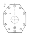
図面にはフロアスプリング全体の内、ここで関心のあるケーシングカバー1だけが示されている。
Only the
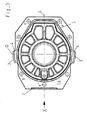
図3には、本発明によるケーシングカバー1aを下から見た図が示されている。同じケーシングカバー1aを上から見た図が図5に、図3の矢印Xの方向から見た図が図4に示されている。 FIG. 3 shows a view of the casing cover 1a according to the present invention as viewed from below. FIG. 5 is a view of the same casing cover 1a as viewed from above, and FIG. 4 is a view as viewed from the direction of the arrow X in FIG.
ケーシングカバー1aには従来の形式でねじ穴a′〜e′が設けられており、これらのねじ穴にはケーシングカバー1aをフロアスプリングのケーシング(図示せず)に結合するためのねじが挿入可能である。 The casing cover 1a is provided with screw holes a 'to e' in a conventional manner, and screws for connecting the casing cover 1a to a casing (not shown) of a floor spring can be inserted into these screw holes. It is.
図面から判るように、ケーシングカバー1aの下面から突出した補強ショルダ2,3が設けられている。 As can be seen from the drawing, reinforcing shoulders 2 and 3 projecting from the lower surface of the casing cover 1a are provided.
これらの補強ショルダ2,3の内の一方、つまり補強ショルダ2はケーシングカバー1aの一方の端面と整合するように形成されており且つケーシングカバー1aの長手方向中心軸線Lに対して真ん中に延在している。補強ショルダ2は直線的な延在部を有しており且つ長手方向中心軸線Lに対してほぼ直角に延びている。 One of the reinforcing shoulders 2 and 3, that is, the reinforcing shoulder 2 is formed so as to be aligned with one end face of the casing cover 1a and extends in the middle with respect to the longitudinal central axis L of the casing cover 1a. is doing. The reinforcing shoulder 2 has a linear extension and extends substantially perpendicular to the longitudinal central axis L.
他方の2つの補強ショルダ3は、それぞれケーシングカバー1aの横方向側面に設けられている。これらの補強ショルダ3は、ケーシングカバー1aの横方向中心軸線Qと交差しており且つ補強ショルダ2のように直線的に延びているのではなく、屈曲部が設けられている。 The other two reinforcing shoulders 3 are respectively provided on the lateral side surfaces of the casing cover 1a. These reinforcing shoulders 3 intersect with the lateral central axis Q of the casing cover 1a and do not extend linearly like the reinforcing shoulder 2, but are provided with bent portions.
図示の屈曲部の代わりに、補強ショルダ3は例えば湾曲されて形成されていてもよい。 Instead of the illustrated bent portion, the reinforcing shoulder 3 may be formed to be curved, for example.
ケーシングカバー1aの横方向側面に設けられた補強ショルダ3は突出部4に形成されている。これらの突出部4はケーシングカバー1aの平面内で横方向中心軸線Qの方向で外向きに延びている。この場合、補強ショルダ3も突出部の外縁部と整合して延びている。 The reinforcing shoulder 3 provided on the lateral side surface of the casing cover 1 a is formed on the protruding portion 4. These protrusions 4 extend outward in the direction of the lateral central axis Q in the plane of the casing cover 1a. In this case, the reinforcing shoulder 3 also extends in alignment with the outer edge of the protrusion.
補強ショルダはケーシングカバー1aの任意の位置に配置されていてよいと理解される。この場合の配置形式は軸線Q及び/又はLに対して対称的又は非対称的に構成されてよい。同様に、形状も特定の1形状に縛られない。 It is understood that the reinforcing shoulder may be disposed at any position on the casing cover 1a. The arrangement form in this case may be configured symmetrically or asymmetrically with respect to the axes Q and / or L. Similarly, the shape is not bound to one specific shape.
Claims (10)
ケーシングカバー(1a)が少なくとも1つの縁部域に補強ショルダ(2,3)を有していることを特徴とする、フロアスプリング。 A floor spring having a casing for accommodating a closing mechanism, wherein the casing is covered with a casing cover, and the casing cover supports a shaft of a closing mechanism that supports a door or the like.
Floor spring, characterized in that the casing cover (1a) has a reinforcing shoulder (2, 3) in at least one edge region.
Applications Claiming Priority (2)
| Application Number | Priority Date | Filing Date | Title |
|---|---|---|---|
| DE10339106A DE10339106A1 (en) | 2003-08-22 | 2003-08-22 | Floor spring |
| PCT/EP2004/008921 WO2005021912A1 (en) | 2003-08-22 | 2004-08-10 | Floor spring |
Publications (1)
| Publication Number | Publication Date |
|---|---|
| JP2007503536A true JP2007503536A (en) | 2007-02-22 |
Family
ID=34202013
Family Applications (1)
| Application Number | Title | Priority Date | Filing Date |
|---|---|---|---|
| JP2006523568A Withdrawn JP2007503536A (en) | 2003-08-22 | 2004-08-10 | Floor spring |
Country Status (13)
| Country | Link |
|---|---|
| US (1) | US20070186376A1 (en) |
| EP (1) | EP1658413B1 (en) |
| JP (1) | JP2007503536A (en) |
| KR (1) | KR20060058113A (en) |
| CN (1) | CN1839240B (en) |
| AT (1) | ATE432404T1 (en) |
| BR (1) | BRPI0413636A (en) |
| DE (2) | DE10339106A1 (en) |
| DK (1) | DK1658413T3 (en) |
| ES (1) | ES2327236T3 (en) |
| NO (1) | NO20061108L (en) |
| RU (1) | RU2006108862A (en) |
| WO (1) | WO2005021912A1 (en) |
Families Citing this family (1)
| Publication number | Priority date | Publication date | Assignee | Title |
|---|---|---|---|---|
| US9681187B2 (en) * | 2014-06-24 | 2017-06-13 | Lg Electronics Inc. | Method for controlling broadcast receiving device |
Family Cites Families (12)
| Publication number | Priority date | Publication date | Assignee | Title |
|---|---|---|---|---|
| US2085593A (en) * | 1934-02-19 | 1937-06-29 | Norton Lasier Company | Door closing and checking device |
| US2544252A (en) * | 1949-04-29 | 1951-03-06 | George W Houlsby Jr | Door closer |
| US2669745A (en) * | 1950-04-22 | 1954-02-23 | Eskilstuna Jernmanufaktur Akti | Door-closing device |
| US2752627A (en) * | 1953-02-26 | 1956-07-03 | George W Houlsby Jr | Pivotal door check device |
| US3106743A (en) * | 1960-04-20 | 1963-10-15 | Oscar C Rixson Company | Door closer assembly |
| US3222711A (en) * | 1962-06-01 | 1965-12-14 | Rixson Inc | Pivot bracket for center-hung doors |
| GB1050496A (en) * | 1963-12-24 | 1900-01-01 | ||
| US3618160A (en) * | 1969-10-16 | 1971-11-09 | Rixson Inc | Door control unit |
| DE2202084A1 (en) * | 1972-01-18 | 1973-08-02 | Dorma Baubeschlag | AUTOMATIC DOOR CLOSER |
| DE2522410A1 (en) * | 1975-05-21 | 1977-01-20 | Ver Baubeschlag Gretsch Co | FLOOR DOOR CLOSER |
| AU7812487A (en) * | 1987-09-16 | 1989-03-09 | Tong-Lung Metal Industry Co., Ltd. | Door closer |
| DE29501929U1 (en) * | 1995-02-07 | 1995-04-06 | Dorma Gmbh & Co Kg | Door closer |
-
2003
- 2003-08-22 DE DE10339106A patent/DE10339106A1/en not_active Withdrawn
-
2004
- 2004-08-10 KR KR1020067003129A patent/KR20060058113A/en not_active Application Discontinuation
- 2004-08-10 DE DE502004009534T patent/DE502004009534D1/en active Active
- 2004-08-10 DK DK04763941T patent/DK1658413T3/en active
- 2004-08-10 BR BRPI0413636-5A patent/BRPI0413636A/en not_active Application Discontinuation
- 2004-08-10 US US10/569,058 patent/US20070186376A1/en not_active Abandoned
- 2004-08-10 ES ES04763941T patent/ES2327236T3/en active Active
- 2004-08-10 JP JP2006523568A patent/JP2007503536A/en not_active Withdrawn
- 2004-08-10 EP EP04763941A patent/EP1658413B1/en active Active
- 2004-08-10 WO PCT/EP2004/008921 patent/WO2005021912A1/en active Application Filing
- 2004-08-10 CN CN2004800241110A patent/CN1839240B/en active Active
- 2004-08-10 AT AT04763941T patent/ATE432404T1/en not_active IP Right Cessation
- 2004-08-10 RU RU2006108862/12A patent/RU2006108862A/en not_active Application Discontinuation
-
2006
- 2006-03-08 NO NO20061108A patent/NO20061108L/en not_active Application Discontinuation
Also Published As
| Publication number | Publication date |
|---|---|
| WO2005021912A1 (en) | 2005-03-10 |
| EP1658413A1 (en) | 2006-05-24 |
| CN1839240B (en) | 2011-08-10 |
| ES2327236T3 (en) | 2009-10-27 |
| US20070186376A1 (en) | 2007-08-16 |
| CN1839240A (en) | 2006-09-27 |
| DK1658413T3 (en) | 2009-09-21 |
| EP1658413B1 (en) | 2009-05-27 |
| KR20060058113A (en) | 2006-05-29 |
| DE10339106A1 (en) | 2005-03-17 |
| NO20061108L (en) | 2006-03-08 |
| ATE432404T1 (en) | 2009-06-15 |
| RU2006108862A (en) | 2007-10-20 |
| DE502004009534D1 (en) | 2009-07-09 |
| BRPI0413636A (en) | 2006-10-17 |
Similar Documents
| Publication | Publication Date | Title |
|---|---|---|
| JP4108642B2 (en) | Spring hinges for furniture | |
| JP4534889B2 (en) | Keyboard device | |
| US6971816B2 (en) | Mounting device for control cable | |
| JP2007503536A (en) | Floor spring | |
| JP6245503B2 (en) | Piano handle switch | |
| CN101031698B (en) | Hinge with pushing force during opening for furniture units with cornice | |
| JP3592009B2 (en) | Switch box structure | |
| JP4009231B2 (en) | Adjustable hinge | |
| ITMI981663A1 (en) | CLOSURE FOR VEHICLE DOOR | |
| JP2940796B2 (en) | Casing assembly structure | |
| KR200270253Y1 (en) | The moving structure of a nose-pad | |
| JP4443434B2 (en) | Electrical equipment storage box | |
| JP4620514B2 (en) | Instrument panel support device | |
| JPH0248598Y2 (en) | ||
| JP2002036960A (en) | Glove box attaching structure | |
| JPS5841743Y2 (en) | Terminal device lid opening/closing device | |
| JP3388407B2 (en) | Closed plate structure for iron lid | |
| JPS6012076Y2 (en) | folding door | |
| JP2002089144A (en) | Door body of equipment storage rack | |
| JPH0547429Y2 (en) | ||
| JP4188183B2 (en) | Outdoor handle device | |
| US964562A (en) | Handle for caskets and other articles. | |
| KR100426276B1 (en) | Personal computer with easy assembly structure | |
| KR200270252Y1 (en) | The moving structure of a nose-pad | |
| JP2500610Y2 (en) | magnet catch |
Legal Events
| Date | Code | Title | Description |
|---|---|---|---|
| A761 | Written withdrawal of application |
Free format text: JAPANESE INTERMEDIATE CODE: A761 Effective date: 20070313 |