JP2007503527A - Apparatus and / or method for depositing metal and / or metal alloy from metal organic electrolyte - Google Patents
Apparatus and / or method for depositing metal and / or metal alloy from metal organic electrolyte Download PDFInfo
- Publication number
- JP2007503527A JP2007503527A JP2006524288A JP2006524288A JP2007503527A JP 2007503527 A JP2007503527 A JP 2007503527A JP 2006524288 A JP2006524288 A JP 2006524288A JP 2006524288 A JP2006524288 A JP 2006524288A JP 2007503527 A JP2007503527 A JP 2007503527A
- Authority
- JP
- Japan
- Prior art keywords
- solvent
- product
- coating
- rinsing
- cleaning
- Prior art date
- Legal status (The legal status is an assumption and is not a legal conclusion. Google has not performed a legal analysis and makes no representation as to the accuracy of the status listed.)
- Pending
Links
Images
Classifications
-
- C—CHEMISTRY; METALLURGY
- C25—ELECTROLYTIC OR ELECTROPHORETIC PROCESSES; APPARATUS THEREFOR
- C25D—PROCESSES FOR THE ELECTROLYTIC OR ELECTROPHORETIC PRODUCTION OF COATINGS; ELECTROFORMING; APPARATUS THEREFOR
- C25D17/00—Constructional parts, or assemblies thereof, of cells for electrolytic coating
- C25D17/02—Tanks; Installations therefor
-
- C—CHEMISTRY; METALLURGY
- C25—ELECTROLYTIC OR ELECTROPHORETIC PROCESSES; APPARATUS THEREFOR
- C25D—PROCESSES FOR THE ELECTROLYTIC OR ELECTROPHORETIC PRODUCTION OF COATINGS; ELECTROFORMING; APPARATUS THEREFOR
- C25D5/00—Electroplating characterised by the process; Pretreatment or after-treatment of workpieces
- C25D5/003—Electroplating using gases, e.g. pressure influence
-
- C—CHEMISTRY; METALLURGY
- C25—ELECTROLYTIC OR ELECTROPHORETIC PROCESSES; APPARATUS THEREFOR
- C25D—PROCESSES FOR THE ELECTROLYTIC OR ELECTROPHORETIC PRODUCTION OF COATINGS; ELECTROFORMING; APPARATUS THEREFOR
- C25D3/00—Electroplating: Baths therefor
- C25D3/02—Electroplating: Baths therefor from solutions
- C25D3/42—Electroplating: Baths therefor from solutions of light metals
Landscapes
- Chemical & Material Sciences (AREA)
- Engineering & Computer Science (AREA)
- Chemical Kinetics & Catalysis (AREA)
- Electrochemistry (AREA)
- Materials Engineering (AREA)
- Metallurgy (AREA)
- Organic Chemistry (AREA)
- Application Of Or Painting With Fluid Materials (AREA)
- Manufacture And Refinement Of Metals (AREA)
- Chemical Vapour Deposition (AREA)
- Cleaning By Liquid Or Steam (AREA)
- Cleaning And De-Greasing Of Metallic Materials By Chemical Methods (AREA)
Abstract
Description
本発明は、有機金属電解液から金属及び/又は金属合金、特に有機溶媒中の金属有機錯塩を製品上に沈積し、並びに製品を被覆する少なくとも1つの被覆部、少なくとも1つの追加的な処理部及び概ね酸素及び/又は水分の浸透なく製品を装置から水路を通して搬出入する少なくとも1つのスルースチャンバを有する装置及び方法に関する。 The present invention deposits a metal and / or metal alloy, particularly a metal organic complex salt in an organic solvent, from an organometallic electrolyte on a product, and at least one coating for coating the product, at least one additional treatment unit. And generally relates to an apparatus and method having at least one sluice chamber for carrying a product in and out of the apparatus through a water channel without penetration of oxygen and / or moisture.
伝統的なガルバノ技術ではよくあるように、アルミニウム、マグネシウム及びこれらの水溶液系からの合金の電気沈積はこれら元素の非常に低い電位が原因で可能ではない。過去数十年間アルミニウム、マグネシウム及びこれらの非水溶液系からの合金の沈積に多数のアプローチがあったものの、アルミニウムアルキル又はマグネシウムアルキルを含有する錯体からの沈積のみが工業規模で成功した。ここでは対応する適切な工程管理及び分析性を備えた電解液の変形体(electroryte variant)が様々な適用のほとんどに対して多少の成功を収めてきた。いくつかの事例ではこれらを用いた大規模な工業用途の適用も可能になった。 As is common in traditional galvano technology, electrodeposition of alloys from aluminum, magnesium and their aqueous systems is not possible due to the very low potential of these elements. Although there have been a number of approaches to the deposition of aluminum, magnesium and alloys from these non-aqueous systems over the past few decades, only deposition from aluminum alkyl or magnesium alkyl containing complexes has been successful on an industrial scale. Here, electrolyte variants with corresponding appropriate process control and analysis have had some success for most of the various applications. In some cases, large-scale industrial applications using these have become possible.
各電解液の変形体の生成に使用されるアルキル金属類は周知のとおり酸素及び水と非常に激しく反応して、例えばアルコキシ化合物類又はアルミニウムオキサン類といった反応生成物を形成する。これら反応生成物はもはや、この電解液の処方に使用されるアルカリ金属類又はハロゲン化アルカリ類と追加的な錯体を形成することはできない。可溶性不純物として電解液中に残存し、及びその際電気伝導性を低下させる。同様にこれら反応生成物の濃度の上昇に伴い最大使用可能電流密度は増加し、これによってこの被覆方法工程は費用対効果、及び場合によっては良好な品質も喪失する。 As is well known, the alkyl metals used to produce each electrolyte variant react very vigorously with oxygen and water to form reaction products such as alkoxy compounds or aluminum oxanes. These reaction products can no longer form additional complexes with alkali metals or alkali halides used in the formulation of the electrolyte. It remains in the electrolyte as a soluble impurity and in this case reduces electrical conductivity. Similarly, the maximum usable current density increases with increasing concentrations of these reaction products, thereby losing the coating process step cost-effectively and in some cases also good quality.
上述の一連の問題は1987年11月には既にニュレンベルグのグオルグ・シオン・オーム技術研究所で検討され、電解液の長い使用寿命及び最適な層品質を保証するためには、アルキル系金属有機電解液が存在する被覆系への酸素及び/又は水分の浸透を概ね回避するべきであるとの結果を得た。被覆系への酸素及び水の浸透を原因とする化学的又は電気化学的な欠点とは別に、被覆系への酸素及び/又は水の浸透を回避することもまたこのような系の信頼性高く及び安全な動作、とりわけ加工における信頼性及び製造における安全性に関して及び環境に関して非常に重要である。 The above-mentioned series of problems were already studied in November 1987 at the Guorg Zion Ohm Technical Laboratory in Nuremberg. In order to guarantee the long service life of the electrolyte and the optimum layer quality, alkyl-based metal organic electrolysis Results have been obtained that oxygen and / or moisture penetration into the coating system in which the liquid is present should generally be avoided. Apart from the chemical or electrochemical defects due to oxygen and water penetration into the coating system, it is also reliable to avoid such oxygen and / or water penetration into the coating system. And safe operation, especially with regard to process reliability and manufacturing safety and with respect to the environment.
種々の最先端技術の被覆系が周知であり、被覆系各部への酸素及び/又は水分の浸透を回避するアプローチも部分的に含まれている。このような系では、水又は酸素を含有しない非プロトン性電解液からの金属又は合金を含有する継ぎ目のない金属又は非金属製品の電解被覆が連続工程において提供されており、独国特許第197 16 493 C2号に記載されている。この目的のためにすすぎ及び乾燥工程が加えられ、これは水溶液の残留物を除去することを意図している。これに加えて、被覆された継ぎ目のない製品をシステムからスルースシステムを介して排出することが提供されている。スルースチャンバは、封入液を含有し、外側のチャンバに含有される空気に対して障壁の働きをする中央チャンバを含む。第3のチャンバは不活性ガスを含有する。これに加えて、工程で使用されるすべての液体が、調製、洗浄及び再循環される再生回路が設けられている。 Various state-of-the-art coating systems are well known, and some approaches to avoid oxygen and / or moisture penetration into each part of the coating system are included. In such systems, electrolytic coating of seamless metal or non-metallic products containing metals or alloys from aprotic electrolytes that do not contain water or oxygen is provided in a continuous process, and DE 197 16 493 C2. A rinsing and drying step is added for this purpose, which is intended to remove aqueous residue. In addition, it is provided to discharge the coated seamless product from the system through the sluice system. The sluice chamber contains a central chamber that contains the fill liquid and acts as a barrier to the air contained in the outer chamber. The third chamber contains an inert gas. In addition, a regeneration circuit is provided in which all the liquid used in the process is prepared, washed and recirculated.
独国特許第30 23 827 C2号によると、外部とは密閉された管状セルであり、これを介して処理対象であり及び陰極と接触する材料が陽極に沿って軸方向に特に連続的に移動できるセルが周知である。管状セルからの電解液の好ましくない排出を防止するとともにセルへの空気雰囲気の浸透を防止するために、管状セルを保護ガスで加圧することができる。この公報によると、数個のチャンバから構成されるスルース構造も提供されており、ここへは各チャンバを互いに密閉するために不活性ガス及び/又は不活性液体を導入することができる。 According to German Patent No. 30 23 827 C2, the outside is a sealed tubular cell, through which the material to be processed and in contact with the cathode moves particularly continuously along the anode in the axial direction Possible cells are well known. In order to prevent undesirable discharge of the electrolyte from the tubular cell and to prevent the penetration of air atmosphere into the cell, the tubular cell can be pressurized with a protective gas. According to this publication, a sluice structure consisting of several chambers is also provided, into which inert gas and / or inert liquid can be introduced to seal the chambers together.
独国特許第199 32 524 C1号によると、電気化学処理の目的、特に導電性又は導電性にされた部品の電気化学被覆の目的で、これら部品は、電解質溶液で充填された容器、又は処理中回転し及びしたがって部品全面を被覆する回転バスケットへと持ち込まれる。容器は気密にされている。バスケット内での部品の処理は全く再投入なしに行われる。各液体又は溶液は単に一度容器へと汲み入れられ、及び再度そこから汲み出される。容器は乾燥目的でその都度遠心分離され、及びその際電解質溶液の残留物はバスケットを推し進めることによって遠心分離される。このシステムはその設計を理由に金属有機電解液の沈積には適していない。 According to German Patent No. 199 32 524 C1, for the purpose of electrochemical treatment, in particular for the purpose of electrochemical coating of conductive or conductive parts, these parts can be filled with electrolyte solutions or treated. It is brought into a rotating basket which rotates in the middle and thus covers the entire part. The container is airtight. The processing of the parts in the basket takes place without any reintroduction. Each liquid or solution is simply pumped into the container once and again from there. The vessel is centrifuged each time for drying purposes, and the electrolyte solution residue is then centrifuged by pushing the basket. This system is not suitable for metal-organic electrolyte deposition because of its design.
また独国特許第41 18 416 A1号によると部品、好ましくは相対的に肉薄のものを被覆する装置が周知であり、この装置において被覆は、互いに隣接するよう配置された容器内に部品を持ち込むことによって行われる。その際、容器又は槽は不活性ガス雰囲気中にある。これに加えて、すすぎ槽、エッチング槽及び沈積槽が設けられている。共通の容器内に種々の槽を配置する際に、仕切として形成され、処理対象の部品が浸透できるスルースが設けられる。この目的で、この浸透可能な仕切は浸透領域内において、弾性材料から成り、軸周りに回転し、密閉が形成されるような態様で互いに移動し及び密閉が形成されるような態様で容器の境界壁に面して摺動する一対のローラによって形成される。
これら上記の公報によると、装置は各装置の一部領域において、装置への酸素又は水分のすべての浸透を回避しようと試みることになる。この目的のため装置の一部のみに例えばすすぎ及び乾燥装置又は3部スルースチャンバ等が設けられている。 According to these above publications, the device will attempt to avoid all permeation of oxygen or moisture into the device in some areas of each device. For this purpose, only a part of the device is provided, for example, with a rinsing and drying device or a three-part sluice chamber.
このように本発明の目的は、金属有機電解液から金属及び/又は金属合金を沈積する装置及び方法であって、安全に関連する問題が何ら発生せず、並びに、装置からの溶媒のすべての排出及び特に使用される電解液系の装置の周囲雰囲気からの酸素及び水分とのすべての反応を概ね完全に回避することができる装置及び方法を提供することである。 Thus, an object of the present invention is an apparatus and method for depositing metals and / or metal alloys from a metal organic electrolyte, which does not cause any safety-related problems, and that all of the solvent from the apparatus. It is to provide an apparatus and method which can almost completely avoid the exhaustion and in particular all reactions with oxygen and moisture from the ambient atmosphere of the electrolyte-based apparatus used.
この目的は請求項1の序文に記載の装置において、被覆部からの装置の他の部分のガスと関連した分離又は被覆部に対するこれら他の部分の密閉のための分離装置を備えた少なくとも1つのサイフォンすすぎ装置、並びに、不活性ガスで満たすことができ及び被覆部、少なくとも1つのサイフォンすすぎ装置及び少なくとも1つの追加的な被覆部を概ね密閉する少なくとも1つのフード構成材が設けられることによって実現される。請求項17の序文に記載の方法に関して目的は、製品の概ね溶媒損失のない水路を通した搬出入が少なくとも1つのスルースチャンバを介して金属及び/又は金属合金の沈積装置へと提供されていること、製品がガスを概ね排除して少なくとも1つの被覆部へと移送されること、製品が少なくとも1つの被覆部で被覆されること、被覆された製品は被覆部から少なくとも1つのサイフォンすすぎ装置を介して少なくとも1つの出力部へとガスを概ね排除して移送されること、及び完成製品が少なくとも1つの追加的なスルースチャンバを介して水路を通して搬出され、ここでは不活性ガス雰囲気ベルが装置の全部分の上方に保持されていることによって実現される。本発明の拡張は、従属請求項に定義(define)されている。
The object is to provide at least one device according to the preamble of
これによって、酸素及び水又は水分とともに他の不純物の被覆電解液へのキャリーオーバーをできる限り低減することが可能な金属及び/又は金属合金を沈積する装置及び方法が提供される。これによって、被覆電解液の長い使用寿命を保証することができる。溶媒排出物といった好ましくない反応生成物の形成は、非常に急激に抑えるか又は概ね完全に防止することができる。ガス雰囲気を装置各部へと分離し、装置のこれら各部を互いに密閉する分離装置を備えたサイフォンすすぎ装置を設けることによって、装置各部間で酸素及び水分の拡散障壁が精密に設けられている。装置各部を囲繞している概ね密閉されたフード構成材中のガス雰囲気は、装置各部において最適となるよう設定することができる。これによって、ガス雰囲気を介した電解液領域への溶媒の移動をすべて防止することも可能である。被覆電解液の洗浄液又は他の溶媒との化学的不適合が高頻度に発生するため、装置各部のガス雰囲気の分離自体に特に利点があることが証明された。これによって安全な及び信頼性の高い作動が可能である。1つには、概ね密閉されたフード構成材を設けることによって、装置内の全雰囲気の封入、及びこれによる装置周囲の外部雰囲気からの分離が可能である。これによって、蒸発している溶媒は装置から排出される前に回収され、システムの対応する部分へと再循環される。こうして、装置周囲の周囲雰囲気の混入も概ね排除することができる。もう1つには、フード構成材内で、一定圧であるが、同時に周囲雰囲気中の圧力に対応する圧力とは異なる圧力に維持することが可能である。好ましくは、フード構成材各部の少なくとも一部において、装置周囲の雰囲気と比較して僅かな超過圧力が維持され及び監視される。好ましくは、フード構成材中での一定圧力、及び/又はフード構成材中で外部及び/又は周囲雰囲気と比較して僅かな超過圧力を維持する少なくとも1つの圧力維持装置が設けられている。したがって、装置への外部雰囲気の意図しない浸透、及びしたがって装置内のガス雰囲気の混入をこうして概ね回避することができる。 This provides an apparatus and method for depositing metals and / or metal alloys that can reduce the carryover of oxygen and water or moisture along with other impurities into the coating electrolyte as much as possible. Thereby, a long service life of the coating electrolyte can be guaranteed. The formation of undesirable reaction products, such as solvent effluent, can be suppressed very rapidly or almost completely prevented. Oxygen and moisture diffusion barriers are precisely provided between the various parts of the apparatus by providing a siphon rinsing device with a separating device that separates the gas atmosphere into the various parts of the apparatus and seals these parts of the apparatus together. The gas atmosphere in the generally sealed hood component surrounding each part of the device can be set to be optimal in each part of the device. As a result, it is possible to prevent all of the solvent from moving to the electrolyte region through the gas atmosphere. Since chemical incompatibility of the coating electrolyte with the cleaning solution or other solvent frequently occurs, it has been proved that there is a particular advantage in the separation of the gas atmosphere of each part of the apparatus itself. This allows safe and reliable operation. For one, by providing a generally hermetically sealed hood component, it is possible to enclose the entire atmosphere within the device and thereby separate it from the external atmosphere surrounding the device. This allows the evaporating solvent to be recovered before it is discharged from the apparatus and recycled to the corresponding part of the system. Thus, contamination of the ambient atmosphere around the apparatus can be generally eliminated. Second, it is possible to maintain a constant pressure in the hood component, but at the same time a pressure different from the pressure corresponding to the pressure in the ambient atmosphere. Preferably, a slight overpressure is maintained and monitored in at least some of the hood components as compared to the atmosphere surrounding the device. Preferably, at least one pressure maintenance device is provided which maintains a constant pressure in the hood component and / or a slight overpressure in the hood component compared to the external and / or ambient atmosphere. Thus, unintentional permeation of the external atmosphere into the device and thus contamination of the gas atmosphere within the device can thus be largely avoided.
概ね一定の圧力をフード構成材中特に各フード部中で、したがって特に装置の外部雰囲気と比較して僅かに超過圧力を維持できるようにするために、好ましくは少なくとも1つのガス緩衝装置が設けられ、及び各部、特に最初及び/又は最後の部分に接続され、又は接続することができる。したがってこの種のガス緩衝装置は、製品の水路を通った搬出入を原因とした圧力のばらつきが起こりうるため、好ましくは装置の入口及び出口に設けられる。ガス緩衝装置は、フード構成材中に事前選択可能な公差の範囲外にある超過圧力が発生する場合に充填され、フード構成材中に事前選択可能な公差の範囲外にある不足圧力が発生する場合、例えばスルースチャンバを不活性ガスで満たすためにガス雰囲気が各フード構成材から除去される場合に、空にされる。 In order to be able to maintain a substantially constant pressure in the hood components, in particular in each hood part, and thus in particular slightly compared to the external atmosphere of the device, preferably at least one gas buffer is provided. , And each part, in particular the first and / or last part. Therefore, this type of gas buffering device is preferably provided at the inlet and outlet of the device, since pressure variations can occur due to loading and unloading of the product through the water channel. Gas shock absorbers are filled when an overpressure occurs outside the preselectable tolerance range in the hood component, and an underpressure outside the preselectable tolerance range occurs in the hood component. In some cases, for example, when the gas atmosphere is removed from each hood component to fill the sluice chamber with inert gas, it is emptied.
好ましくは、少なくとも1つの酸素監視装置が、少なくとも1つのスルースチャンバ及び/又はフード構成材の部分に設けられている。好ましくは、溶媒濃度を監視する少なくとも1つの装置もスルースチャンバに設けられている。これによって、装置各部中にあるガス雰囲気中の酸素及び/又は溶媒含有量を絶えず監視することが可能である。スルースチャンバは、装置への空気又は酸素の導入を防止する役割を果たすため、スルースチャンバ雰囲気の酸素含有量は、製品の水路を通った搬入、その際に製品と一緒に導入された空気の排出及び例えば不活性ガスによるチャンバのすすぎの後に、定期的に監視される。スルースチャンバがフード構成材に対して開放されている場合、フード構成材及び装置の他の部分への酸素の浸透を回避することができるよう、チャンバ内の酸素含有量はできる限りゼロに近づくべきである。装置からの溶媒の排出も、できる限りゼロに近づくよう低下させるべきである。装置の外部雰囲気への接続を示すスルースチャンバ中の溶媒含有量を監視できるようにするために、スルースチャンバには溶媒濃度を監視する装置も設けられている。酸素及び/又は溶媒含有量が、事前決定及び/又は設定が可能、又は設定されている閾値を超える限り、ガスのスルースチャンバからの導出入にポンピング回数を適合させること、及び/又は少なくとも1つのスルースチャンバでの酸素含有量を低下させるための不活性ガスによるポンピングサイクル中の追加的なすすぎ段階を誘発することが可能である。例えば、混入されたガス雰囲気を汲み出すには長いポンピングサイクルが提供される。また、酸素含有量に関して不活性ガス雰囲気ベルを監視することができ、酸素含有量はできる限りゼロに近づけるべきである。これら手段によって、装置の不活性ガス雰囲気ベルへの酸素の混入がほとんどない、又は全くないことを最適な態様で保証することができ、この場合、最適な被覆成果並びに製品処理中の非常に高い安全性及び信頼性を達成することができる。 Preferably, at least one oxygen monitoring device is provided in the at least one sluice chamber and / or part of the hood component. Preferably, at least one device for monitoring the solvent concentration is also provided in the sluice chamber. This makes it possible to continuously monitor the oxygen and / or solvent content in the gas atmosphere in each part of the apparatus. Since the sluice chamber serves to prevent the introduction of air or oxygen into the device, the oxygen content of the sluice chamber is determined by the introduction of the product through the water channel and the discharge of the air introduced with the product. And periodically monitored, for example, after rinsing the chamber with an inert gas. If the sluice chamber is open to the hood component, the oxygen content in the chamber should be as close to zero as possible so that oxygen penetration into the hood component and other parts of the device can be avoided. It is. Solvent emissions from the apparatus should also be reduced as close to zero as possible. In order to be able to monitor the solvent content in the sluice chamber indicating its connection to the external atmosphere of the device, the sluice chamber is also provided with a device for monitoring the solvent concentration. As long as the oxygen and / or solvent content exceeds a set threshold that can be pre-determined and / or set, adapt the number of pumps to derivation of gas from the sluice chamber, and / or at least one It is possible to induce an additional rinsing step during the pumping cycle with an inert gas to reduce the oxygen content in the sluice chamber. For example, a long pumping cycle is provided to pump out a mixed gas atmosphere. Also, the inert gas atmosphere bell can be monitored for oxygen content and the oxygen content should be as close to zero as possible. By these means it can be ensured in an optimal manner that there is little or no oxygen contamination in the inert gas atmosphere bell of the device, in this case the optimum coating result as well as very high during product processing Safety and reliability can be achieved.
好ましくは、製品表面を洗浄及び/又は前処理する洗浄及び/又は活性化部、及び/又は装置から製品を水路を通って搬出する少なくとも1つの出力部が設けられている。好ましくは、少なくとも1つの洗浄及び/又は活性化部は、被覆対象製品を洗浄する洗浄液及び/又は表面を活性化し又は接着促進剤層を生成する活性化液を含む1つ又は複数の密閉可能な処理槽を含む。このような洗浄及び/又は活性化部では、原製品の洗浄が有利に可能であり、酸素の存在しない製品のブランク面を製造することができる。これによって後続する被覆に対して最適な接着強度を保証することが可能である。接着強度をさらに向上させるために、装置のこの部分で製品表面に接着促進剤層を有利に塗布することができる。密閉可能な処理槽を設けることによって、各製品が各処理槽に挿入されることが予定されている場合これらを選択的に開放することが可能である。こうして、フード雰囲気への処理液の好ましくない蒸発はさらに抑制することができる。 Preferably, a cleaning and / or activation part for cleaning and / or pretreatment of the product surface and / or at least one output part for carrying the product out of the device through the water channel are provided. Preferably, the at least one cleaning and / or activating part comprises one or more sealables comprising a cleaning liquid for cleaning the product to be coated and / or an activating liquid for activating the surface or creating an adhesion promoter layer. Includes treatment tank. In such a cleaning and / or activation part, the original product can be advantageously cleaned and a blank surface of the product free of oxygen can be produced. This makes it possible to guarantee an optimum adhesive strength for subsequent coatings. To further improve the bond strength, an adhesion promoter layer can be advantageously applied to the product surface at this part of the device. By providing a process tank that can be sealed, it is possible to selectively open each product when it is planned to be inserted into each process tank. In this way, undesirable evaporation of the treatment liquid into the hood atmosphere can be further suppressed.
好ましくは、少なくとも1つの洗浄及び/又は活性化部は、少なくとも1つの処理槽の後方に配置され、事前処理された製品をすすぎ及び洗浄及び/又は活性化部からの化学品のキャリーオーバーをすべて防止する少なくとも1つのすすぎ装置を含む。厳密には、洗浄及び/又は活性化部の次にしたがって被覆部の前にサイフォンすすぎ装置を設ける際には、洗浄及び/又は活性化部からサイフォンすすぎ装置へ、及び後続の被覆電解質への化学物質のキャリーオーバーをすべて防止するためには、事前処理された製品のこのようなすすぎを提供することは理にかなっているのではない。好ましくは、溶媒調製及び/又は再生装置が設けられ、及びこのようなすすぎ装置に接続されている。洗浄された溶媒は、再度サイフォンすすぎ装置に再度再循環され、一方、この段階の前に配置された洗浄された洗浄液又は活性化液、又は処理槽中の他の流体をこれら処理槽中に再循環することができる。洗浄のために、洗浄された溶媒の蒸留及び引き続き保存が提供される。 Preferably, the at least one cleaning and / or activation part is arranged behind the at least one treatment tank to rinse the pre-treated product and carry over any chemical carryover from the cleaning and / or activation part. Including at least one rinsing device to prevent; Strictly speaking, when a siphon rinsing device is provided in front of the coating according to the cleaning and / or activation section, the chemistry from the cleaning and / or activation section to the siphon rinsing apparatus and to the subsequent coating electrolyte. In order to prevent any material carryover, it does not make sense to provide such a rinse of the pre-treated product. Preferably, a solvent preparation and / or regeneration device is provided and connected to such a rinsing device. The washed solvent is again recirculated to the siphon rinser, while the washed washing or activation liquid or other fluid in the treatment tanks placed before this stage is recirculated into these treatment tanks. Can circulate. For washing, distillation and subsequent storage of the washed solvent is provided.
好ましくは、洗浄及び/又は活性化部のための少なくとも1つの溶媒調製及び/又は再生装置が、その迂回路に設けられる。これによって、被覆中、又は前洗浄時の溶媒、並びに電解液又は他の洗浄液及び浸漬液、及び後続する処理部の恒常的な洗浄が可能である。 Preferably, at least one solvent preparation and / or regeneration device for the washing and / or activation part is provided in the detour. This allows permanent cleaning of the solvent during coating or pre-cleaning, as well as the electrolyte or other cleaning liquid and immersion liquid, and the subsequent processing section.
好ましくは少なくとも1つのスルースチャンバは、溶媒分離及び再循環装置及び/又はガス振動システムにも接続され、又は接続することができる。好ましくは少なくとも1つのスルースチャンバが洗浄及び/又は活性化部の入口に設けられ、及び/又は少なくとも1つのスルースチャンバが出力部の出口に設けられる。好ましくは水路を通った搬入段階では、製品は少なくとも1つのスルースチャンバへと導入される。その際スルースチャンバは外部雰囲気で充填され、密閉され、及び引き続き排気され、したがって外部雰囲気はチャンバ外部から運送され及び引き続き不活性ガスで満たされる。その後水路を通った搬出段階において製品は装置の第1の処理部へと導入される。装置からの水路を通った搬出段階では製品はフード雰囲気からスルースチャンバへと持ち込まれ、チャンバはフード雰囲気からスルースチャンバへと取り出され、密閉され、及びフード雰囲気がそこから汲み出され及びフード部へと再循環される。スルースチャンバは引き続き開放し、及び製品を取り出すことが可能である。その後スルースチャンバは再び密閉され、浸透しつつある外部雰囲気は排出され、及びチャンバは不活性ガスで満たされる。特に好ましくは汲み出されたスルース雰囲気が調製され、乾燥した不活性ガス及び洗浄された溶媒が工程に、特に乾燥した不活性ガスは不活性ガス雰囲気ベルに、及び洗浄された溶媒は処理槽に再循環される。したがってガス振動システムは、スルースチャンバからスルースチャンバの雰囲気の汲出後、乾燥した不活性ガスをフード雰囲気へと汲み出すことを含んでいる。 Preferably, the at least one sluice chamber is or can be connected to a solvent separation and recirculation device and / or a gas oscillation system. Preferably at least one sluice chamber is provided at the inlet of the cleaning and / or activation part and / or at least one sluice chamber is provided at the outlet of the output part. Preferably, in the carry-in stage through the water channel, the product is introduced into at least one sluice chamber. The sluice chamber is then filled with an external atmosphere, sealed and subsequently evacuated so that the external atmosphere is transported from outside the chamber and is subsequently filled with inert gas. Thereafter, the product is introduced into the first processing section of the apparatus in the unloading stage through the water channel. In the unloading stage through the waterway from the device, the product is brought from the hood atmosphere into the sluice chamber, the chamber is removed from the hood atmosphere to the sluice chamber, sealed, and the hood atmosphere is pumped from it to the hood section And recirculated. The sluice chamber can continue to open and the product can be removed. The sluice chamber is then sealed again, the permeating external atmosphere is evacuated, and the chamber is filled with inert gas. Particularly preferably, a pumped sluice atmosphere is prepared, dry inert gas and washed solvent in the process, especially dry inert gas in the inert gas atmosphere bell and washed solvent in the treatment tank. Recirculated. Thus, the gas vibration system includes pumping dry inert gas into the hood atmosphere after pumping the sluice chamber atmosphere from the sluice chamber.
したがって、被覆前には、好ましくは装置出口に設けられたスルースチャンバへの水路を通った搬出中に外部雰囲気が被覆対象製品と一緒に持ち込まれるため、及び、被覆後に製品は、装置端部に設けられたスルースチャンバの開放及びスルースチャンバへの外部雰囲気の浸透によって再び外部雰囲気へと持ち出されるため、スルースチャンバの領域内に溶媒分離及び再循環装置を設けることがそれ自体有利であることが証明された。そこでは厳密には、製品の水路を通った搬出入の間、酸素とともに水分が装置に浸透することができ、蒸発した溶媒は装置から出ることができる。好ましく設けられた冷却装置を介して、スルースチャンバから汲み出され及び溶媒が混入した雰囲気をこうして冷却し、及び溶媒は分離、収集、及び再循環することができる。溶媒分離工程において、汲み出されたガスは乾燥され、及び引き続き再びフード雰囲気へと再循環することができる。水路を通った搬出領域における溶媒分離を介して、製品から付着した溶媒残量物を除去することができ、溶媒排出が概ね全く発生しないよう装置を概ね完全に乾燥させておくことができる。また製品の水路を通った搬出領域では、汲出工程中に排出された溶媒残留物が再凝縮、収集され、及び引き続き工程特に最後のサイフォンすすぎ装置へと再循環される。 Therefore, before coating, the external atmosphere is preferably brought together with the product to be coated during unloading through the water channel to the sluice chamber provided at the device outlet, and after coating the product is at the device end. Providing a solvent separation and recirculation device in the region of the sluice chamber itself proves advantageous as it is brought back to the external atmosphere by opening the sluice chamber and penetration of the external atmosphere into the sluice chamber It was done. Strictly speaking, during the loading and unloading of the product through the water channel, moisture along with oxygen can permeate the device and the evaporated solvent can leave the device. Via a preferably provided cooling device, the atmosphere pumped out of the sluice chamber and contaminated with the solvent can thus be cooled, and the solvent can be separated, collected and recycled. In the solvent separation step, the pumped gas can be dried and subsequently recirculated back to the hood atmosphere. Solvent residue adhering to the product can be removed via solvent separation in the carry-out area through the water channel, and the device can be kept almost completely dry so that almost no solvent discharge occurs. Also in the discharge area through the product channel, the solvent residues discharged during the pumping process are recondensed, collected and subsequently recycled to the process, in particular the last siphon rinse device.
好ましくは、特に不活性ガス雰囲気を凝縮し、及び凝縮された溶媒部を各回路特に処理槽に再循環することによって、不活性ガス雰囲気ベルも洗浄される。好ましくは凝縮液分離装置を備えた冷却装置が、キャリーオーバー及び/又は蒸発した溶媒残留物を回収するために、特にフード構成材及び/又は被覆部に設けられ、及び/又は少なくとも1つのスルースチャンバに接続されている。特に好ましくは、フード部及び/又はフード構成材中の1つ又は複数の冷却装置は、溶媒を処理槽及び/又は被覆槽へと再循環する溶媒再循環装置及び/又は少なくとも1つのサイフォンすすぎ装置を含む。これによって、フード構成材中のガス雰囲気から溶媒混入物を再び除去することも可能である。溶媒のうち冷却装置へと凝縮された部分は、引き続き各フード部の対応する処理槽へと再循環することができる。蒸発している液体は通常フード部ごとに異なりガス雰囲気中の異物が常に異なるため、好ましくは各冷却装置は通常各フード部に設けられている。こうして、再循環が各フード部内で有利に行われる。 Preferably, the inert gas atmosphere bell is also cleaned, particularly by condensing the inert gas atmosphere and recirculating the condensed solvent portion to each circuit, particularly the treatment vessel. A cooling device, preferably equipped with a condensate separation device, is provided, in particular in the hood component and / or covering, and / or at least one sluice chamber, in order to recover carryover and / or evaporated solvent residues It is connected to the. Particularly preferably, the one or more cooling devices in the hood part and / or the hood component are a solvent recirculation device and / or at least one siphon rinsing device for recirculating the solvent to the treatment tank and / or the coating tank. including. Thereby, it is also possible to remove the solvent contaminants from the gas atmosphere in the hood component again. The portion of the solvent that has been condensed to the cooling device can subsequently be recirculated to the corresponding treatment tank of each hood. Since the evaporated liquid is different for each hood part and foreign substances in the gas atmosphere are always different, preferably each cooling device is usually provided in each hood part. Thus, recirculation is advantageously performed within each hood.
好ましくは少なくとも1つの被覆部は、フード構成材への溶媒の制御されない蒸発を防止するために密閉可能な少なくとも1つの被覆槽を含んでいる。特に蒸発された溶媒を凝縮する少なくとも1つの冷却装置及び凝縮された溶媒を収集する少なくとも1つの集水装置も、少なくとも1つの被覆槽のガス空間に設けられている。これに加えて少なくとも1つの被覆部は、少なくとも1つの出力すすぎ装置を含むことができる。被覆工程の後、付着している電解液残留物を除去するために、製品は出力すすぎ装置に設けられたすすぎ槽へと入れられる。すすぎ槽を洗浄するために、溶媒分離及び/又は再生装置からの洗浄された溶媒の再循環が特に提供される。 Preferably, the at least one coating includes at least one coating bath that can be sealed to prevent uncontrolled evaporation of the solvent into the hood component. In particular, at least one cooling device for condensing the evaporated solvent and at least one water collecting device for collecting the condensed solvent are also provided in the gas space of the at least one coating vessel. In addition, at least one covering may include at least one output rinsing device. After the coating process, the product is put into a rinsing tank provided in the output rinsing device in order to remove the adhering electrolyte residue. In order to clean the rinsing tank, solvent separation and / or recycling of the washed solvent from the regenerator is specifically provided.
サイフォンすすぎ装置は、装置の各部、したがって特に洗浄及び/又は活性化部、処理部及び出力部を分離するために設けられているため、これら過渡領域において略非反応性溶媒を提供することがそれ自体有利であることが証明済である。このように少なくとも1つのサイフォンすすぎ装置には好ましくは不活性溶媒が充填されている。これによって装置各部からの互いに適合性のない好ましくない化学反応を概ね回避することができる。好ましくは少なくとも1つのサイフォンすすぎ装置は、上方にあるフード部が区分けされるよう配置され、取り付けされた仕切を備えた密閉可能な二重すすぎ装置を含む。サイフォン装置のすすぎ槽に浸漬するこのような仕切を設けることによって、装置の異なるフード部を気密に分離することが提供できる。サイフォンすすぎ装置を介した製品の輸送を可能にするために、具体的にはフード部内に設けられた特に好適な輸送装置は仕切を浸透することができないため、特に、製品を仕切の下方で横移動させる少なくとも1つの輸送装置が二重すすぎ装置中に配置され又は配置することができ、これによって二重すすぎ装置に洗浄液を充填している時に輸送装置が液面より下に位置するようになる。これによって、洗浄液への製品の完全な浸漬が保証されることによって、装置の前工程部から後工程部への化学品及び/又はガス雰囲気のキャリーオーバーを防止するために、製品の全面を洗浄し及び好ましくは不活性すすぎ液で洗浄することができる。 Since the siphon rinsing device is provided to separate parts of the device, and thus in particular the cleaning and / or activation part, the processing part and the output part, it is possible to provide a substantially non-reactive solvent in these transient regions. It has proven itself advantageous. Thus, at least one siphon rinsing device is preferably filled with an inert solvent. In this way, undesirable chemical reactions that are not compatible with each other can be largely avoided. Preferably, the at least one siphon rinsing device comprises a sealable double rinsing device arranged with the upper hood section partitioned and with an attached partition. By providing such a partition immersed in the rinsing tank of the siphon device, it is possible to provide an airtight separation of the different hood parts of the device. In order to allow the product to be transported through the siphon rinse device, in particular, a particularly suitable transport device provided in the hood part cannot penetrate the partition, so in particular the product is placed laterally under the partition. At least one transporting device to be moved can be arranged or arranged in the double rinsing device so that the transporting device is located below the liquid level when the double rinsing device is filled with cleaning liquid . This ensures that the product is completely immersed in the cleaning solution, thereby cleaning the entire surface of the product to prevent carryover of chemicals and / or gas atmosphere from the front-end part to the back-end part of the equipment. And preferably can be washed with an inert rinse.
好ましくはこれに加えて、少なくとも1つの電解液/溶媒分離装置が被覆部領域に設けられる。特に、電解液/溶媒分離装置は、少なくとも1つの被覆槽から排出された電解液/溶媒浸漬液からの溶媒を蒸留する蒸留装置を含む。これに加えて、結果として生じる洗浄された溶媒を出力すすぎ槽へと再循環する装置及び/又は電解液を電解液回路へと再循環する装置が設けられる。 Preferably in addition to this, at least one electrolyte / solvent separator is provided in the covering region. In particular, the electrolytic solution / solvent separation device includes a distillation device for distilling the solvent from the electrolytic solution / solvent immersion liquid discharged from at least one coating tank. In addition, an apparatus for recirculating the resulting washed solvent to the output rinse tank and / or an apparatus for recirculating the electrolyte to the electrolyte circuit is provided.
被覆溶液したがって電解質溶液の洗浄は、このように被覆部の迂回路にて行うことができる。この洗浄装置は特に被覆槽の後方に続き、ここでは特に洗浄された溶媒が被覆槽の後に配置された出力すすぎ槽に、特に電解液が被覆槽に再循環される。 The washing of the coating solution and thus the electrolyte solution can thus be carried out in the detour of the coating part. This cleaning device follows in particular behind the coating tank, in which the specifically cleaned solvent is recirculated to the output rinsing tank arranged after the coating tank, in particular the electrolyte to the coating tank.
電解質溶液及び/又は溶媒は好ましくは閉回路内で行われる。これによって、装置の他の槽の混入は概ね回避される。有利には、化学物質のキャリーオーバーを防止するために、電解液及び/又は溶媒及び/又はすすぎ液の洗浄又は調製が行われる。製品及び/又は洗浄液及び/又は活性化液に付着する電解液のキャリーオーバーを防止するために、好ましくはこれに加えて種々のすすぎ装置におけるすすぎが提供されている。これらすすぎ装置は、装置及び被覆工程の種々の地点で、特に装置各部の出力領域に設けることができる。 The electrolyte solution and / or solvent is preferably performed in a closed circuit. This generally avoids contamination of other tanks of the device. Advantageously, the electrolyte and / or solvent and / or rinse is washed or prepared to prevent chemical carryover. In addition to this, rinsing in various rinsing devices is preferably provided in order to prevent carryover of the electrolytic solution adhering to the product and / or the cleaning and / or activating liquid. These rinsing devices can be provided at various points in the device and coating process, particularly in the output areas of each part of the device.
とりわけ、任意の形態の製品が本発明に記載の装置を用いて被覆することができ、したがって溶媒が堆積しうる背部の切欠のある製品も可能である。現在の技術水準では、このような堆積を除去することができず、この理由のため溶媒の被覆を信頼性高く除去することができない。本発明に記載の方法及び本発明に記載の装置によって、任意の形態の製品の溶媒残留物の除去が信頼性高い態様で可能である。 In particular, any form of product can be coated using the apparatus described in the present invention, and thus a product with a back notch on which a solvent can be deposited is also possible. With the current state of the art, such deposits cannot be removed and for this reason the solvent coating cannot be removed reliably. The method according to the invention and the apparatus according to the invention make it possible to remove the solvent residues of any form of product in a reliable manner.
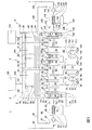
本発明をより詳細に説明するため、実施例を図面を用いてさらに詳細に説明する。図面は、本発明に記載の金属沈積装置の包括図を示す。 In order to describe the present invention in more detail, examples will be described in more detail with reference to the drawings. The drawing shows a comprehensive view of a metal deposition apparatus according to the present invention.
実施例:
図は、金属及び/又は金属合金を沈積する装置1の包括図としての概略図を示す。装置は洗浄及び/又は活性化部2、被覆部3及び出力部4を含む。これに加えて、これら上記3個の部品すべてを略密閉的に囲繞するフード構成材5を含む。フード構成材は、3つの部分50、51、52へとさらに区分される。この3つのフード部は、各仕切53、54によって互いに分離されている。
Example:
The figure shows a schematic diagram as a general view of the
洗浄及び/又は活性化部2は、第1のスルースチャンバ20、第1の処理槽21、第2の処理槽22及びすすぎ槽23を含む。これに加えて洗浄及び/又は活性化部は、第1のサイフォンすすぎ装置60の一部を含む。サイフォンすすぎ装置60は、仕切53によって2つの部分へと分けられることにより二重すすぎ装置を形成し、これは部分2及び部分3から到達できるが、それ以外は拡散障壁を形成する。すべての槽又は洗浄装置は各カバー24、25、26、27、62によって密閉することができる。スルースチャンバ20は、製品のスルースチャンバへの移動を可能にするスルースドア28を含む。好ましくはこのような製品は図示しない輸送台車を介してスルースチャンバへと移動する。
The cleaning and / or activating unit 2 includes a
スルースチャンバ20は、溶媒を回収する装置70及びガス振動システム80へと接続される。溶媒の回収装置は、冷却トラップ71、弁72、凝縮液分離装置73とともに、弁72とスルースチャンバ20との間の管路74、冷却トラップ71と凝縮液分離装置73との間の管路75及び凝縮液分離装置73と第1の処理槽21との間の再循環回路76を有する。
The
ガス振動システム80は、真空ポンプ81、3個の弁82、83,84及びスルースチャンバ20と第1のバルブ82との間の管路85、弁82と真空ポンプ81との間の追加的な管路86、真空ポンプ81とフード構成材への再循環管路にある弁83との間の管路87とともに弁83とフード構成材50との間の追加的な管路88を含む。管路87は弁84にもつながり、そこから追加的な管路89は外部雰囲気へと外部につながる。これを介して、空気を装置から吹き出すことができる。
The
これに加えて、溶媒調製及び/又は再生装置90は洗浄及び/又は活性化部2に接続されている。溶媒調製及び/又は再生装置は、蒸留装置91及び凝縮液集水タンク92を含む。蒸留装置は、すすぎ槽23からの管路93を介して供給を受ける。蒸留装置91と凝縮液集水タンク92との間に管路94も設けられている。蒸留装置91内で洗浄された洗浄液は、管路95、ポンプ96及び追加的な管路97を介して第2の処理槽22へと再循環される。蒸留装置によって蒸留された清浄な溶媒は、凝縮液集水タンク92から管路98、ポンプ99及び管路100を介してすすぎ槽23に汲み戻すことができる。
In addition, the solvent preparation and / or
これに加えて必要に応じて、すすぎ槽23と第2の処理槽22との間には、過剰量の溶媒が再循環された場合のすすぎ槽の溢れを回避するために、オーバーフロー管路29が設けられている。
In addition, if necessary, an
次に過剰溶媒は、オーバーフロー管路29を介して第2の処理槽22に再循環される。
The excess solvent is then recycled to the
これに加えて洗浄及び/又は活性化部2のフード部50は、各処理、すすぎ及び他の槽との間で製品7を横断させる輸送装置55を含む。このために輸送装置は、被覆対象の製品7を吊り下げるフック57を本実施例では設けた輸送台車56を含む。ここでフック57は、輸送台車56上に固定されて横移動することができるため、フック上の製品を各槽までゆっくりと低下し、そこから吊り上げることができる。
In addition, the
これに加えてフード部50は冷却装置58を含む。図では冷却コイルの形態で示されている。この冷却コイルを介して、蒸発した溶媒を凝縮し、同じくフード部50に設けられた集水装置59に収集することができる。図では、集水装置は集水トラフの形態で示されている。集水トラフ又は集水装置59に収集された溶媒は、ドレン管路101を介して第1の被覆槽21へと再循環することができる。このように、溶媒の第1及び第2の被覆槽が存在しうる。原則として、さらに多くの被覆槽も設けることができるが、本図では可能な一実施形態を再生しているにすぎない。いくつかのすすぎ槽を設けることも可能である。同様に原則的には、二つ以上のスルースチャンバを設けることも可能であろう。
In addition, the
フード部50中で均一な圧力を維持できるようにするために、このフード部内にあるガスの洗浄にもかかわらず及び洗浄されたガスの再循環にもかかわらず、ガス緩衝剤容器120がフード構成材5の外側に設けられている。
In order to be able to maintain a uniform pressure in the
ガス緩衝剤容器120は、管路121を介してフード部50の内部へと接続される。この管路121を介して、ガス緩衝剤容器とフード部50との間でガスの二者交換が行われる。これによって、事前に設定された超過圧力、及びとりわけフード部内の一定圧力を維持することが可能である。
The
洗浄及び/又は活性化部2中の酸素及び溶媒含有量を確認するために、フード部50領域内の第1の酸素センサ122とともに、スルースチャンバ20における第2の酸素センサ123及び溶媒濃度センサ124を設ける。設定された閾値の行き過ぎを監視し及び必要に応じてスルースチャンバの汲上サイクル及びガス交換を選択的に適合させるために、すべてのセンサは監視及び制御装置(図示せず)に接続することができる。
In order to check the oxygen and solvent contents in the cleaning and / or activating unit 2, the
被覆部3は、上述のように二重すすぎ装置として形成されているサイフォンすすぎ装置60の第2の部分を含む。カバー62を介してサイフォンすすぎ装置60に持ち込まれた製品の輸送のために、サイフォンすすぎ装置60には、図示するように特に輸送台車を備えることができる輸送装置66が設けられる。サイフォンすすぎ装置を介した輸送の後、サイフォンすすぎ装置60のカバー63を介した被覆部3側で製品を取り出すことができる。被覆部3は、2個の被覆槽30、31とともに出力すすぎ槽32及び追加的なサイフォンすすぎ装置61の第1の部分を含む。これら槽にはそれぞれ、カバー33、34、35が設けられている一方、サイフォンすすぎ装置は被覆部側にカバー64を設けている。2つの被覆槽30、31のカバー33、34の下方にあるガス空間には、電解液から蒸発する溶媒を被覆中及び特に被覆槽の後に凝縮し及びすすぎ槽32へと導くために、冷却コイル38、39及び集水トラフ38、39がそれぞれ設けられている。
The covering 3 includes a second part of the siphon rinse
また被覆部3には電解液/溶媒分離装置110の迂回路中にある電解液を洗浄するために、被覆部に接続された洗浄装置が設けられている。これによって、顕著な量の電解液のキャリーオーバーがないことが保証され、これによって概ね閉じた材料回路を生成することができる。電解液を洗浄するために、流体は2つの被覆槽30、31から管路111を介して蒸留装置112へと導かれる。これに加えて、凝縮液集水タンク113が設けられ、管路114を介して蒸留装置112へと接続される。洗浄された電解液は、管路115、117及びポンプ116を介して被覆槽30へと再循環される。電解液/溶媒混合物から蒸留された溶媒は凝縮液集水タンク113に収集され、管路118、ポンプ119及び再循環管路102を介して出力すすぎ槽32内にあるすすぎ槽に再循環される。こうして、出力すすぎ槽32内のすすぎ槽には常に洗浄された溶媒が供給される。出力すすぎ槽の水位が上昇しすぎた場合、オーバーフロー管路103が出力すすぎ槽と第2の被覆槽31との間に設けられている。このオーバーフロー管路を介して、過剰のすすぎ液特にしたがって溶媒が第2の被覆槽に戻る。
In addition, the coating unit 3 is provided with a cleaning device connected to the coating unit in order to clean the electrolytic solution in the detour of the electrolytic solution /
洗浄及び/又は活性化部2と同様に被覆部3も、被覆対象の製品7を被覆部の各槽間で輸送できるようにするために、輸送台車56及びフック57を備えた輸送装置55を含む。これに加えて、冷却コイルの形態の冷却装置58とともに凝縮された溶媒用の集水装置59としての集水トラフが設けられている。ドレン管路104を介して、収集された凝縮済の溶媒が第1の被覆槽30に再循環される。
Similar to the cleaning and / or activation part 2, the covering part 3 also has a
出口部4はサイフォンすすぎ装置61の第2の部分を含む。これには、輸送装置60と同様輸送装置67も設けられている。これを介してカバー64を介してサイフォンすすぎ装置に持ち込まれた製品は、仕切54の他の側にあり及びサイフォンすすぎ装置61のカバー65を有する部分へと輸送される。サイフォンすすぎ装置60内と同じように、輸送はサイフォンすすぎ装置中のすすぎ液の液面より下方で行われる。これによって被覆部から出力部への製品の輸送中に、概ね完全なガスの排除が可能となる。
Outlet portion 4 includes a second portion of siphon rinse
これに加えて、出力部は被覆された製品を装置から水路を通って搬出する第2のスルースチャンバ40を含む。スルースチャンバには、カバー41が設けられている。これに加えて、スルースドア42を含む。スルースチャンバ20と同様にスルースチャンバ40にも、溶媒を回収する装置130及びガス振動システム140が設けられている。溶媒を回収する装置にも、冷却トラップ131、スルースチャンバ40と冷却トラップ131との間の弁132、凝縮液分離装置133、弁132とスルースチャンバ40との間の管路134、凝縮液分離装置133と冷却トラップ131との間の管路135及び凝縮液分離装置133とサイフォンすすぎ装置61との間の溶媒再循環管路136が設けられている。
In addition, the output includes a second sluice chamber 40 that carries the coated product out of the device through a water channel. A
ガス振動システム140は、真空ポンプ141、3個の弁142、143及び144とともに間に配置された数本の管路を含む。第1の管路145はスルースチャンバ40から第1の弁142へとつながり、第2の管路146は弁142からポンプ141へとつながる。それには、冷却トラップ71と真空ポンプ81との間の装置70と同じように、冷却トラップ131からの管路もつながっている。ポンプ141からは管路147が弁143へとつながり、そこから再循環管路148がフード部52につながる。また管路147は真空ポンプから弁144にもつながり、これを介して特にスルースチャンバ40からの空気が管路149を介して外側に吹き出すことができる。
The
フード部52は、製品7を捕捉し及び各槽よりも下げることができるためのフック57を含む輸送台車56を備えた輸送装置55も含む。同様に冷却コイル58が冷却装置として設けられ、及び集水トラフ59が、集水トラフから流れ込み管路105を介してサイフォンすすぎ装置61へと再循環されることができる凝縮済の溶媒用に提供される。
The
出力部4には、ガス緩衝剤容器125及びフード部52内部とガス緩衝剤容器125との間の管路126も設けられている。これによって、出力部においてできる限り一定のガス圧力が維持されることが保証される。もっとも、ちょうど、スルースチャンバ40からの完成製品の水路を通った搬出工程後の外部雰囲気からの汲出後に、出力部からのフード雰囲気がスルースチャンバ40に水路を通って搬入される間の過小圧力と同じように、例えば乾燥した不活性ガスを管路145を介して再循環することによって出力部のフード部において超過圧力が発生しうる。
The output unit 4 is also provided with a gas
具体的には完成製品を水路を通って搬出し、浄化されたガスを再循環するための出力部の恒常的な開閉を理由として、できる限り継続的な態様で出力部中の酸素及び溶媒含有量を決定し、及び必要に応じて是正すべく介入し、及びこうしてスルースチャンバからの好ましくない溶媒排出をできる限り回避するために、及び溶媒の損失及び装置からの有害な排出ガスをできる限り低く保つために、第1及び第2の酸素センサ127、128及び溶媒濃度センサ129が設けられている。第1の酸素センサ127が上部フード部52に設けられ、一方第2の酸素センサ128及び溶媒濃度センサ129がスルースチャンバ40に設けられている。また被覆部3上方のフード部51にはこのような酸素センサ150が設けられている。
Specifically, oxygen and solvent content in the output section in a continuous manner as much as possible due to the constant opening and closing of the output section to carry the finished product through the water channel and recirculate the purified gas To determine the amount and intervene to correct as necessary, and thus to avoid as much as possible undesirable solvent emissions from the sluice chamber, and to minimize solvent loss and harmful emissions from the equipment In order to maintain, first and
電解液、洗浄液、溶媒及びガス雰囲気の各再生工程での被覆の過程をさらに詳細に以下に記載する。 The coating process in each regeneration step of the electrolytic solution, cleaning solution, solvent, and gas atmosphere will be described in more detail below.
被覆対象の製品は、スルースドア28を介して第1のスルースチャンバ20へと持ち込まれる。これは特に輸送台車を介して行われるが、図示されていない。通路を通った搬入工程の途中でスルースチャンバには必然的に外部雰囲気(空気)が充填され及び引き続き密閉される。その後スルースチャンバは真空ポンプ81並びに管路85及び86を介して排気される。この目的のため弁82が開放される。その後は、混入されていない唯一の空気はスルースチャンバ内に存在するため、管路89及び開放された弁84を介して外部に直接排出することができる。引き続きスルースチャンバはフード部50からの不活性ガスで満たされる。その後直ちにスルースチャンバとフード部50との間に配置された内部カバー24を開くことができ、及び製品を不活性ガス雰囲気内に持ち込むことができる。スルースチャンバは1ないし2mbar未満まで最終的に排気することができるため、第1のフード部50に浸透できる酸素の量は非常に少なく、及びさらに不活性ガス特に窒素及び酸素で中間すすぎを行うことも可能である。
The product to be coated is brought into the
流入に必要であり、フード部50から取り出されているガスの量によって、ガス緩衝剤容器が設けられていなければ圧力の下降をおそらくきたすであろう。これを回避し及び例えば窒素といった新しい不活性ガス、恒常的にフード部に持ち込まれる必要がありそのためフード部で微量の酸素及び水の痕跡が見出されることを防止するために、ガス緩衝剤容器120はフード部50に接続され、体積が変化する可能性があるためフード部50内圧力を概ね一定に維持している。
Depending on the amount of gas required for inflow and withdrawn from the
フード部内の雰囲気の監視は酸素センサによって恒常的に実施することができる。溶媒濃度は溶媒濃度センサ124を介して監視される。システムへの酸素の分散を確認することは、特に電解液の使用寿命及び被覆性質に関して理にかなったことであるが、処理の全般的な信頼性及びシステム全体の作動安全性に関しても理にかなっている。
Monitoring of the atmosphere in the hood part can be constantly performed by an oxygen sensor. The solvent concentration is monitored via a
製品がカバー24を介してフード部50に持ち込まれた後、カバー24が再び閉じ、スルース雰囲気を汲み出すことができ、ここで不活性ガス/溶媒混合物がスルース雰囲気中に存在し及び汲み出される。これは弁72を管路74を介して開放した後行われることによって不活性ガス/溶媒混合物が冷却トラップ71を介して導かれる。凝縮後、得られた乾燥した不活性ガスは、真空ポンプ81、管路87、次に開放弁83及び管路88を介してフード部50へと再循環される。不活性ガスは洗浄されたガスとして、再びフード部50中の雰囲気に利用可能とすることができる。ガス緩衝剤容器120中の体積の増加によって、過剰なガス体積が収集されることによって、フード部50内圧力を概ね一定に抑えることができる。
After the product is brought into the
堆積する凝縮済の溶媒は管路75を介して凝縮液分離装置73へと導入され、及び特に定期的に再発生する態様で溶媒再循環管路76を介して第1処理槽21へと再循環することができる。引き続き、排気されたスルースチャンバには再び新鮮な不活性ガスが流入し、及び新しい製品を装置に持ち込むために外部雰囲気へのドアすなわちスルースドア28を再び開放することができる。
The condensed solvent that accumulates is introduced into the
輸送装置55を介して、製品を特に洗浄液を含む処理槽21、22へと持ち込むことができ、及びそこで前洗浄することができ、及び後続する被覆において最適な接着強度を保証するために、特にブランクの酸素を含まない表面を製造することができる。これに加えて接着促進剤層を槽内でその上に塗布することができる。溶媒の蒸発を概ね回避するためにカバー25、26が設けられている。同様に、好ましくは商品又は製品が持ち込まれ又は持ち出される場合のみそれぞれ開放されるすすぎ槽の上に、カバー27が設けられている。この後に配置されたすすぎ槽23は、処理槽21、22からサイフォンすすぎ装置60への化学品のキャリーオーバーを回避する目的の働きをし、ここでは被覆部中の槽内の被覆電解液へのキャリーオーバーも回避されるべきである。すすぎ槽23の液は洗浄及び/又は活性化部への迂回路に接続されている溶媒調製及び/又は再生装置90を介して定期的に調製されている。
In order to ensure that the product can be brought into the
前処理した製品をすすいだ後、カバー62を介してサイフォンすすぎ装置62へと入れる。仕切53が設けられているため、その上方に存在する2個のフード部50及び51は気密な態様で互いに分離されるが、依然としてサイフォンすすぎ装置60の二重すすぎ装置によって互いに接続され、これを介して製品が通過できる。好ましくはサイフォンすすぎ装置内の液は、被覆電解液中に使用されている溶媒と同一である。洗浄液及び/又は被覆電解液との反応をできる限り回避するために、好ましくは不活性溶媒が使用される。活性化部2及び被覆部3との間にサイフォンすすぎ装置を提供することによって、この利点により、洗浄及び活性化部において、ガス雰囲気を介した電解液領域への溶媒の移動がすべて防止されているため、被覆電解液との適合性が良好でない溶媒も使用することができる。特に被覆対象の製品に伴う溶媒のキャリーオーバーは、蒸留装置91を介したすすぎ槽23中の液の調製によって最も実質的に防止することができる。
After rinsing the pretreated product, it is put into the siphon rinsing
製品をサイフォンすすぎ装置60のカバー63を介して上昇させた後、製品は被覆部3に到達し及びその中で被覆槽30、31へと上昇させることができる。槽内に示されている2つの被覆槽のほか、追加的な出力すすぎ槽32と同じく多数の追加的な槽を設けることができるが、図ではそれらのうち1つだけが示されている。上方にあるフード部51内における制御されていない溶媒の蒸発を回避するために、カバー63、33、34、35及び64は正常な作動では閉鎖されている。好ましくはカバーは、製品を各槽に移動させ又は各槽から取り出すためにのみ開放される。
After the product has been raised through the cover 63 of the siphon rinsing
2つの被覆槽30、31では、冷却コイル36、37及び集水トラフ38、39はそれぞれ槽の液面とカバーとの間のガス空間に位置している。ここで被覆中に電解液から蒸発した溶媒が凝縮され、及び出力すすぎ槽32中のすすぎ槽へと導かれる。電解液回路に設けられた蒸留装置を介して、比較的大量の電解液が定期的に反応に供せられ、間に設けられた管路及びポンプ116を介して槽30に汲み戻される。電解液から蒸留された溶媒は集水タンク113中に収集され、及び管路及びポンプ119を介して出力すすぎ槽32又はその内部のすすぎ槽へともう一度再循環される。出力すすぎ槽32のオーバーフローを回避するために、過剰な溶媒がオーバーフロー管路103を介して回路又は槽31へと再循環される。これによって、顕著な量の電解液が追加的に配置されたサイフォンすすぎ装置61にキャリーオーバーされないことが保証され、この時点であっても既に概ね閉鎖された材料回路を製造することができる。
In the two
被覆部及び出力部の間を接続するサイフォンすすぎ装置61は、構造及び機能においてサイフォンすすぎ装置60と匹敵している。その中に完全に浸漬された製品は、出力部4側のカバー65を介して再び取り出される。新鮮な溶媒が含有されている出力すすぎ槽32内での以前のすすぎによって、被覆部3から以前より付着している電解液残留物が収集され、及び出力部4にはキャリーオーバーされない。これに加えて、各出力すすぎ槽も被覆工程中に発生する過剰な加工熱を有効に利用し及びシステムから除去する働きをする。
The siphon
出力部4には第2のスルースチャンバも設けられ、被覆された製品が持ち込まれる。これはカバー41を介して行われる。スルースチャンバに最終的に被覆された製品を蓄えた後、汲み出し工程もまた開始される。これは、被覆された製品に依然として付着している溶媒残留物を回収する働きをする。これによって、完全に被覆された製品が乾燥した状態で装置から離れることが可能であり、及び溶媒の排出が概ね発生しえない。汲出工程中に蒸発し、冷却トラップ131中で再凝縮され及び凝縮液分離装置133中に収集される溶媒はすべて管路136を介してサイフォンすすぎ装置61へと再循環される。そうでなければ通路を通った搬出工程は、スルース雰囲気及び不活性ガスの汲入及び汲出に関して通路を通った搬入工程と同じように作動する。通路を通った搬出の目的でスルースドア42が開放されている。
The output unit 4 is also provided with a second sluice chamber to carry the coated product. This is done via the
各フード部50、51及び52は不活性ガスで満たされ、及び少なくとも本実施例では自動圧力維持システムを介して周囲雰囲気よりも僅かに超過圧力に一定に保持されている。これによってフード構成材への空気の浸透はすべて回避される。酸素センサ122、123、127、128及び159は各ガス雰囲気中の酸素含有量を恒常的に指示している。事前に定義された閾値の超過が検出されると、ポンプ81、141に関してポンプ時間の適合が実施され、又はスルースチャンバ20、40内での汲出サイクル中の不活性ガスによって追加的なすすぎが開始される。
Each
またサイフォンすすぎ装置をバリア液特に不活性溶媒で充填することによって、特にカバー62、63及び64、65の組み合わせにおいて、この領域における追加的な障壁効果が提供されることによって、被覆部3への酸素及び水分の拡散の追加的な低減が可能になる。スルースチャンバ、真空システム、ガス振動システム及びサイフォンすすぎ装置の組み合わせによって、例えばアルコキシ化合物又はアルミニウムオキサンといった好ましくない反応生成物の形成を有効に抑え又は概ね防止することができるため、金属有機被覆電解液の非常に長い使用寿命及び均一な被覆品質を提供する。
Also, by filling the siphon rinse device with a barrier liquid, particularly an inert solvent, an additional barrier effect in this region is provided, especially in the combination of the
洗浄及び/又は活性化部2用の溶媒調製を提供することによって、酸素及び水分とともに他の化学物質のキャリーオーバー、特に場合によっては所定の被覆電解液と適合性のない洗浄液中に使用される溶媒のキャリーオーバーによる被覆電解液への混入を効果的に防止することができる。溶媒調製及び/又は再生装置90を設けることによって、対応する回路への洗浄液及び溶媒の直接的な再循環が可能になる。これによってすすぎ槽23における混入は非常に低いレベルに維持される。
By providing a solvent preparation for the cleaning and / or activating unit 2, it is used in carryover of other chemicals with oxygen and moisture, especially in cleaning solutions that are incompatible with the given coating electrolyte It is possible to effectively prevent the solvent from being mixed into the coating electrolyte due to carry-over. Providing the solvent preparation and / or
フード部50、51、52内のフード雰囲気を凝縮することによって、フード部はできる限り乾燥し及び純粋に保つことができる。また、輸送時間中に蒸発する製品、特に製品がまだ温かい時に、製品上に見い出される溶媒残留物は、制御された態様で凝縮し、再びドレン管路を介して各材料へと再循環することができる。
By condensing the hood atmosphere in the
上記に記載し及び図面に示した実施例のほかに、他の多数も形成することができ、そのそれぞれにおいて、装置からの溶媒の排出をできる限り低く抑え、及び酸素及び水分とともに他の混入物の被覆電解液へのキャリーオーバーのできる限り大きな低減を達成し、及びこうして好ましくない反応生成物の形成を回避しながら被覆電解液の使用寿命を長くすることが可能である。特に1個のみ又は2個を上回る処理層、被覆槽、サイフォンすすぎ装置及びすすぎ槽を設けることもできる。また追加的な部分、特に追加的な被覆部を設けることができる。またサイフォンすすぎ装置は対応する作用を持つ別の装置によって置き換えることができ、ここでは装置の各部間のガスに関連した分離も可能となる。原則として洗浄及び/又は活性化部をより小さく構成すること又は場合によっては完全に省略してしまうことも可能である。いずれの場合も装置は被覆装置の各ステーションの上方に概ね密閉されたベルを形成し、同時に、雰囲気とともに処理槽又は被覆槽及びすすぎ槽の恒常的な洗浄が存在する。これは迂回路中の洗浄部を各加工部又は処理部へと導くことによって特に単純な態様で達成することができる。代替的にはより複雑な洗浄手順又は回路も可能である。 In addition to the embodiments described above and shown in the drawings, many other forms can be formed, each of which keeps the discharge of solvent from the apparatus as low as possible and other contaminants along with oxygen and moisture. It is possible to achieve the greatest possible reduction in carryover to the coating electrolyte and thus extend the service life of the coating electrolyte while avoiding the formation of undesirable reaction products. In particular, only one or more than two treatment layers, coating tanks, siphon rinsing devices and rinsing tanks can be provided. In addition, additional parts, in particular additional coverings, can be provided. The siphon rinsing device can also be replaced by another device with a corresponding action, in which a gas-related separation between the parts of the device is also possible. In principle, it is also possible to make the cleaning and / or activation part smaller or even to omit it completely. In either case, the apparatus forms a generally sealed bell above each station of the coating apparatus, and at the same time there is a constant cleaning of the treatment tank or coating tank and rinse tank along with the atmosphere. This can be achieved in a particularly simple manner by directing the cleaning section in the detour to each processing section or processing section. Alternatively, more complex cleaning procedures or circuits are possible.
1 装置
2 洗浄及び活性化部
3 被覆部
4 出力部
5 フード構成材
7 製品
20 第1のスルースチャンバ
21 第1の処理槽
22 第2の処理槽
23 すすぎ槽
24 カバー
25 カバー
26 カバー
27 カバー
28 スルースドア
29 オーバーフロー管路
30 第1の被覆槽
31 第2の被覆槽
32 出力すすぎ装置
33 カバー
34 カバー
35 カバー
36 冷却コイル
37 冷却コイル
38 集水トラフ
39 集水トラフ
40 第2のスルースチャンバ
41 カバー
42 スルースドア
50 第1のフード部
51 第2のフード部
52 第3のフード部
53 仕切
54 仕切
55 輸送装置
56 輸送台車
57 フック
58 冷却装置
59 集水装置
60 第1のサイフォンすすぎ装置
61 第2のサイフォンすすぎ装置
62 カバー
63 カバー
64 カバー
65 カバー
66 輸送装置
67 輸送装置
70 溶媒を回収する装置
71 冷却トラップ
72 弁
73 凝縮液分離装置
74 管路
75 管路
76 溶媒回収回路
80 ガス振動システム
81 真空ポンプ
82 弁
83 弁
84 弁
85 管路
86 管路
87 管路
88 管路
89 管路
90 溶媒調製及び/又は再生装置
91 蒸留装置
92 凝縮液集水タンク
93 管路
94 管路
95 管路
96 ポンプ
97 管路
98 管路
99 ポンプ
100 管路
101 ドレン管路
102 再循環管路
103 オーバーフロー管路
104 ドレン管路
105 ドレン管路
110 電解液/溶媒分離装置
111 管路
112 蒸留装置
113 凝縮液集水タンク
114 管路
115 管路
116 ポンプ
117 管路
118 管路
119 管路
120 ガス緩衝剤容器
121 管路
122 第1の酸素センサ
123 第2の酸素センサ
124 溶媒濃度センサ
125 ガス緩衝剤容器
126 管路
127 第1の酸素センサ
128 第2の酸素センサ
129 溶媒濃度センサ
130 溶媒を回収する装置
131 冷却トラップ
132 弁
133 凝縮液分離装置
134 管路
135 管路
136 溶媒再循環管路
140 ガス振動システム
141 真空ポンプ
142 弁
143 弁
144 弁
145 管路
146 管路
147 管路
148 管路
149 管路
150 酸素センサ
DESCRIPTION OF SYMBOLS 1 Apparatus 2 Cleaning | cleaning and activation part 3 Covering part 4 Output part 5 Hood component 7 Product 20 1st sluice chamber 21 1st process tank 22 2nd process tank 23 Rinse tank 24 Cover 25 Cover 26 Cover 27 Cover 28 Sluice door 29 Overflow line 30 First covering tank 31 Second covering tank 32 Output rinsing device 33 Cover 34 Cover 35 Cover 36 Cooling coil 37 Cooling coil 38 Water collecting trough 39 Water collecting trough 40 Second sluice chamber 41 Cover 42 Sluice door 50 1st hood part 51 2nd hood part 52 3rd hood part 53 Partition 54 Partition 55 Transport device 56 Transport cart 57 Hook 58 Cooling device 59 Water collecting device 60 First siphon rinse device 61 Second siphon Rinse device 62 Cover 63 Cover 64 Cover 65 Cover 66 Transport device 67 Transport device 70 Solvent recovery device 71 Cooling trap 72 Valve 73 Condensate separation device 74 Pipe line 75 Pipe line 76 Solvent recovery circuit 80 Gas vibration system 81 Vacuum pump 82 Valve 83 Valve 84 Valve 85 Pipe line 86 Pipe line 87 Pipe Line 88 Pipe line 89 Pipe line 90 Solvent preparation and / or regeneration device 91 Distillation device 92 Condensate collection tank 93 Pipe line 94 Pipe line 95 Pipe line 96 Pump 97 Pipe line 98 Pipe line 99 Pump 100 Pipe line 101 Drain line 102 Recirculation Line 103 Overflow Line 104 Drain Line 105 Drain Line 110 Electrolyte / Solvent Separator 111 Line 112 Distiller 113 Condensate Water Collection Tank 114 Line 115 Line 116 Pump 117 Line 118 Line 119 Line 120 Gas buffer container 121 Line 122 First oxygen sensor 123 Second oxygen sensor 124 Medium concentration sensor 125 Gas buffer container 126 Pipe 127 First oxygen sensor 128 Second oxygen sensor 129 Solvent concentration sensor 130 Solvent recovery device 131 Cooling trap 132 Valve 133 Condensate separator 134 Pipe 135 Pipe 136 Solvent recirculation line 140 Gas vibration system 141 Vacuum pump 142 Valve 143 Valve 144 Valve 145 Pipe line 146 Pipe line 147 Pipe line 148 Pipe line 149 Pipe line 150 Oxygen sensor
Claims (25)
少なくとも1つのサイフォンすすぎ装置(60、61)が、被覆部(3)からの装置の他の部分(2、4)のガスと関連した分離又は被覆部(3)に対するこれら他の部分(2、4)の密閉のための分離装置(53、54)、並びに、不活性ガスで満たすことができ及び被覆部(3)、少なくとも1つのサイフォンすすぎ装置(60、61)及び少なくとも1つの追加的な被覆部(2、4)を概ね密閉する少なくとも1つのフード構成材(5)が設けられること
を特徴とする装置(1)。 Depositing a metal and / or metal alloy, in particular a metal-organic complex salt in an organic solvent, from the metal-organic electrolyte on the product (7) and at least one coating (3) covering the product (7), at least one Including an additional processing section (2, 4) and at least one sluice chamber (20, 40) for carrying the product (7) into and out of the apparatus (1) through a water channel, generally without oxygen and / or moisture penetration. A siphon rinsing device (60, 61) separates the gas from the other part (2, 4) of the device from the covering (3) or of these other parts (2, 4) relative to the covering (3). Separation device (53, 54) for sealing, as well as an inert gas and covering (3), at least one siphon rinsing device (60, 61) and at least one additional covering ( A device (1), characterized in that at least one hood component (5) is provided which generally seals 2, 4).
を特徴とする、請求項1に記載の装置(1)。 In the siphon rinsing device, at least one transport device (66, 67) for moving the product laterally below the partition (53, 54) is or can be arranged, so that the siphon rinsing device (66, 67). The device (1) according to claim 1, characterized in that the transporting device (66, 67) is positioned below the liquid level during the filling with the rinse liquid.
を特徴とする、上記請求項のいずれかに記載の装置(1)。 At least one oxygen monitoring device is provided in at least one sluice chamber (20, 40) and / or part (50, 51, 52) of the hood component (5) and / or monitors the solvent concentration. Device (1) according to any of the preceding claims, characterized in that one device (124, 129) is provided in the sluice chamber (20, 40).
を特徴とする、請求項3に記載の装置(1)。 Immediately after the settable or set threshold is exceeded, at least one oxygen monitoring device is adapted to adapt the pump time to the introduction and discharge of gas into the sluice chamber (20, 40) and / or to at least one sluice chamber ( 20. The device (1) according to claim 3, characterized in that it induces an additional rinsing step with an inert gas during the pumping cycle to reduce the oxygen content in 20, 40).
を特徴とする、上記請求項のいずれかに記載の装置(1)。 At least one pressure maintenance device is provided which maintains a constant pressure in the hood component (5) and / or a slight overpressure in the hood component (5) than the outside or ambient atmosphere, in particular a hood component ( 5) and / or in order to maintain a substantially constant pressure in the hood part (50, 52), at least one gas buffer (120, 125) is provided and / or in particular the first of the device (1). Device (1) according to any of the preceding claims, characterized in that it is connected to or capable of being connected to one (2) and / or the last part (4).
を特徴とする、上記請求項のいずれかに記載の装置(1)。 Device (1) according to any of the preceding claims, characterized in that at least one cleaning and / or activation part (2) for cleaning and / or pre-treating the surface of the product (7) is provided. ).
を特徴とする、請求項6の装置(1)。 The at least one cleaning and / or activation part (2) comprises a cleaning liquid for cleaning the product (7) to be coated and / or an activation liquid for activating the surface, in particular for producing an adhesion promoter layer. One or more sealable treatment tanks (21, 22) and / or at least one cleaning and / or activating part (2) cleans and / or cleans the pretreated product (7). Alternatively, it comprises at least one rinsing device (23) arranged behind the at least one treatment tank (21, 22), preventing carryover of chemicals from the activation part (2), Apparatus (1) according to claim 6.
を特徴とする、上記請求項のいずれかに記載の装置(1)。 At least one coating (3) is sealable (33, 34) at least one coating bath (30, 31) and / or coating to prevent uncontrolled evaporation of the solvent to the hood component (5) Device (1) according to any of the preceding claims, characterized in that it comprises at least one output rinsing tank (32) for rinsing the processed product.
を特徴とする、上記請求項のいずれかに記載の装置(1)。 At least one solvent preparation and / or regeneration device (90), in particular at least one solvent preparation device (90) for one cleaning and / or activation part (2), is provided in the detour. A device (1) according to any of the preceding claims.
を特徴とする、上記請求項のいずれかに記載の装置(1)。 At least one sluice chamber (20, 40) is connected to or connectable to a solvent separation and recirculation device (70, 130) and / or a gas oscillation system (80, 140), Device (1) according to any of the preceding claims.
を特徴とする、上記請求項のいずれかに記載の装置(1)。 At least one cooling device (36, 37, 58, 71, 131) with a condensate separation device (38, 39, 59, 73, 133) for carryover and / or recovery of evaporated solvent residues; Any of the preceding claims, characterized in that they are provided in particular in the hood component (5) and / or the covering (3) and / or connected to at least one sluice chamber (20, 40) (1).
を特徴とする、上記請求項のいずれかに記載の装置(1)。 Including a solvent recirculation device (101, 104, 105) for recycling the solvent to the treatment and / or coating bath (21, 22, 30, 31) and / or including at least one siphon rinsing device (61) At least one cooling device (36, 37) for condensing the evaporated solvent, and at least one water collecting device (38) for collecting the solvent condensed in the gas space of the at least one coating vessel (30, 31). ) 39) including one or more cooling devices in the hood part (50, 51, 52) and / or hood component (5). The device (1) described.
を特徴とする、上記請求項のいずれかに記載の装置(1)。 At least one electrolyte / solvent separator (110) is provided in the region of the coating (3), in particular the electrolyte / solvent separator (110) is discharged from at least one coating vessel (30, 31). There is provided a device (102, 114, 118) comprising a distillation device (112) for distilling the solvent from the liquid / solvent soak, and in particular for recycling the resulting clean solvent to the output rinse tank (32). Device (1) according to any of the preceding claims, characterized in that:
を特徴とする、上記請求項のいずれかに記載の装置(1)。 At least one sluice chamber (20) is provided at the inlet of the cleaning and / or activation part (2) and / or at least one sluice chamber (40) for carrying the product (7) through the passage. A device (1) according to any of the preceding claims, characterized in that it is provided at the outlet of the output part (4).
を特徴とする、上記請求項のいずれかに記載の装置(1)。 Device (1) according to any of the preceding claims, characterized in that the hood component (5) comprises at least one transport device (55) for laterally moving the product between the respective tank and device. .
を特徴とする、上記請求項のいずれかに記載の装置(1)。 Device (1) according to any of the preceding claims, characterized in that at least one siphon rinsing device (60, 61) is filled with an inert solvent.
下記の工程:
少なくとも1つのスルースチャンバ(20)を介した金属及び/又は金属合金を沈積する、特に上記請求項のいずれかに記載の装置(1)への製品(7)の概ね溶媒損失のない水路を通した搬出入、
製品(7)を少なくとも1つの被覆部(3)へのガスを概ね排除して移送すること、
製品(7)を少なくとも1つの被覆部(3)中で被覆すること、
被覆された製品(7)を被覆部(3)から少なくとも1つのサイフォンすすぎ装置(61)を介して少なくとも1つの出力部(4)へとガスを概ね排除して移送すること、及び
完成製品(7)を少なくとも1つの追加的なスルースチャンバ(40)を介して水路を通して搬出し、ここでは不活性ガス雰囲気ベルが装置の全部分(50、51、52)の上方に保持されていること
を含むことを特徴とする方法。 A method of depositing a metal and / or metal alloy, in particular a metal organic complex salt in an organic solvent, onto a product (7) from a metal organic electrolyte,
The following steps:
Depositing metal and / or metal alloy through at least one sluice chamber (20), in particular through the water-free channel of the product (7) to the device (1) according to any of the preceding claims. Carried in and out,
Transferring the product (7) to the at least one coating (3), generally excluding gas,
Coating the product (7) in at least one coating (3);
Transferring the coated product (7) from the coating (3) via the at least one siphon rinsing device (61) to the at least one output (4) in a generally excluded manner, and a finished product ( 7) through the water channel via at least one additional sluice chamber (40), where the inert gas atmosphere bell is maintained above all parts (50, 51, 52) of the device. A method characterized by comprising.
を特徴とする、請求項17に記載の方法。 18. Method according to claim 17, characterized in that the product has been pretreated, in particular its surface has been cleaned and / or activated for further treatment.
を特徴とする、請求項18に記載の方法。 After cleaning and / or activation, the product is introduced via the at least one additional siphon rinsing device (60) into the at least one covering part (3) with a substantial elimination of gas. The method of claim 18.
を特徴とする、請求項17〜19のいずれかに記載の方法。 The electrolyte and / or solvent is led to a generally closed circuit, in particular there is a cleaning or preparation of the electrolyte and / or solvent and / or rinsing solution to avoid chemical carryover The method according to any one of claims 17 to 19.
を特徴とする、請求項17〜20のいずれかに記載の方法。 21. A method according to claim 17, characterized in that they are rinsed in a rinsing device (23, 32) in order to avoid carry-over of cleaning and / or activation and / or electrolytes adhering to the product. The method in any one of.
を特徴とする請求項17〜21のいずれかに記載の方法。 In the carrying-in process through the passage, the product is introduced into at least one sluice chamber (20, 40), the sluice chamber (20) is filled with an external atmosphere, sealed and subsequently evacuated, and the external atmosphere is carried out of the chamber. 22. Method according to any of claims 17 to 21, characterized in that the chamber is subsequently filled with an inert gas and the product is subsequently brought into the first processing part (2) of the apparatus.
を特徴とする、請求項22の方法。 A pumped sluice atmosphere is prepared, the dry inert gas and the washed solvent are in the process, in particular the dry inert gas is in the inert gas atmosphere bell, and the washed solvent is in the first treatment tank (21 23. The method of claim 22 wherein the method is recycled to
を特徴とする、請求項17〜23のいずれかに記載の方法。 At least one sluice chamber atmosphere is monitored for oxygen and / or solvent inclusions and / or an inert gas atmosphere bell is monitored for oxygen inclusions, particularly for the discharge of contaminated atmospheres immediately after a set threshold is exceeded and / or 24. A method according to any of claims 17 to 23, characterized in that the introduction of the cleaned inert gas atmosphere is accelerated or decelerated.
を特徴とする、請求項17〜24のいずれかに記載の方法。 25. The gas of an inert gas atmosphere bell is also cleaned, in particular by condensing the gas and recycling the condensed solvent part to each material circuit. the method of.
Applications Claiming Priority (2)
| Application Number | Priority Date | Filing Date | Title |
|---|---|---|---|
| EP03019235A EP1510600A1 (en) | 2003-08-26 | 2003-08-26 | Process and apparatus for the deposition of metal and metal alloys from organometallic electrolytes |
| PCT/EP2004/009192 WO2005021840A1 (en) | 2003-08-26 | 2004-08-17 | Device and method for separating metals and/or metal alloys from metallo-organic electrolytes |
Publications (2)
| Publication Number | Publication Date |
|---|---|
| JP2007503527A true JP2007503527A (en) | 2007-02-22 |
| JP2007503527A5 JP2007503527A5 (en) | 2009-06-04 |
Family
ID=34089604
Family Applications (1)
| Application Number | Title | Priority Date | Filing Date |
|---|---|---|---|
| JP2006524288A Pending JP2007503527A (en) | 2003-08-26 | 2004-08-17 | Apparatus and / or method for depositing metal and / or metal alloy from metal organic electrolyte |
Country Status (7)
| Country | Link |
|---|---|
| US (1) | US20070114132A1 (en) |
| EP (2) | EP1510600A1 (en) |
| JP (1) | JP2007503527A (en) |
| AT (1) | ATE398195T1 (en) |
| DE (1) | DE502004007361D1 (en) |
| DK (1) | DK1658393T3 (en) |
| WO (1) | WO2005021840A1 (en) |
Families Citing this family (3)
| Publication number | Priority date | Publication date | Assignee | Title |
|---|---|---|---|---|
| DE102004032659B4 (en) | 2004-07-01 | 2008-10-30 | Atotech Deutschland Gmbh | Apparatus and method for the chemical or electrolytic treatment of material to be treated and the use of the device |
| CN103938239A (en) * | 2014-05-11 | 2014-07-23 | 山东建筑大学 | Steel band continuous copper plating I |
| CN103938238B (en) * | 2014-05-11 | 2016-08-03 | 山东建筑大学 | A kind of continuous copper-plating of steel strip method |
Family Cites Families (5)
| Publication number | Priority date | Publication date | Assignee | Title |
|---|---|---|---|---|
| DE3044975C2 (en) * | 1980-11-28 | 1985-10-31 | Siemens AG, 1000 Berlin und 8000 München | Device for the galvanic deposition of aluminum |
| DE3133162C2 (en) * | 1981-08-21 | 1984-08-02 | Siemens AG, 1000 Berlin und 8000 München | Device for the galvanic deposition of aluminum |
| DE3133232A1 (en) * | 1981-08-21 | 1983-03-10 | Siemens AG, 1000 Berlin und 8000 München | DEVICE FOR GALVANIC DEPOSITION OF ALUMINUM |
| DE3231855A1 (en) * | 1982-08-26 | 1984-03-01 | Siemens AG, 1000 Berlin und 8000 München | DEVICE FOR GALVANIC DEPOSITION OF ALUMINUM |
| US4759831A (en) * | 1986-07-04 | 1988-07-26 | Siemens Aktiengesellschaft | Electroplating apparatus particularly for electro-deposition of aluminum |
-
2003
- 2003-08-26 EP EP03019235A patent/EP1510600A1/en not_active Withdrawn
-
2004
- 2004-08-17 US US10/569,658 patent/US20070114132A1/en not_active Abandoned
- 2004-08-17 DK DK04764184T patent/DK1658393T3/en active
- 2004-08-17 JP JP2006524288A patent/JP2007503527A/en active Pending
- 2004-08-17 WO PCT/EP2004/009192 patent/WO2005021840A1/en active IP Right Grant
- 2004-08-17 AT AT04764184T patent/ATE398195T1/en not_active IP Right Cessation
- 2004-08-17 DE DE502004007361T patent/DE502004007361D1/en active Active
- 2004-08-17 EP EP04764184A patent/EP1658393B1/en not_active Not-in-force
Also Published As
| Publication number | Publication date |
|---|---|
| DK1658393T3 (en) | 2008-10-20 |
| EP1510600A1 (en) | 2005-03-02 |
| DE502004007361D1 (en) | 2008-07-24 |
| WO2005021840A1 (en) | 2005-03-10 |
| ATE398195T1 (en) | 2008-07-15 |
| US20070114132A1 (en) | 2007-05-24 |
| EP1658393A1 (en) | 2006-05-24 |
| EP1658393B1 (en) | 2008-06-11 |
Similar Documents
| Publication | Publication Date | Title |
|---|---|---|
| CN100497731C (en) | Substrate processing apparatus and substrate processing method | |
| KR100407869B1 (en) | Cleaning device and cleaning method | |
| WO2001068952A1 (en) | Method and apparatus for electroplating | |
| RU2095162C1 (en) | Method of cleansing parts | |
| JPH06502514A (en) | Semiconductor processing method and device | |
| JP2007138304A (en) | Plating apparatus and method | |
| JP2007332435A (en) | Automatic apparatus for forming metallic film, and method for forming metallic film on wafer | |
| JP2007503527A (en) | Apparatus and / or method for depositing metal and / or metal alloy from metal organic electrolyte | |
| JP2007503527A5 (en) | ||
| JP3171822B2 (en) | Cleaning device and cleaning method | |
| JP5330793B2 (en) | Substrate processing apparatus and substrate processing method | |
| JPH0615239A (en) | Method for vacuum washing and drying and equipment therefor | |
| JP2009253026A (en) | Substrate processing apparatus, substrate processing method, program, and recording medium | |
| JPH0799177A (en) | Immersion treatment apparatus for substrate | |
| JPH07227581A (en) | Vacuum-cleaning and drying method and device therefor | |
| US4759831A (en) | Electroplating apparatus particularly for electro-deposition of aluminum | |
| CN111330906B (en) | Cleaning process | |
| JP2000237703A (en) | Vacuum washing/drying method and device | |
| US20040256219A1 (en) | Device for the electrodeposition of aluminum or aluminum alloys from organometallic electrolytes containing alkyl | |
| JP5147638B2 (en) | Substrate processing apparatus and substrate processing method | |
| JP2002518595A (en) | Electroplating method and electroplating equipment | |
| JP2793700B2 (en) | Sealed aluminum plating equipment | |
| KR100784791B1 (en) | Facility for treating rear process of carbon nano tube, and facility and method for manufacturing carbon nano tube with the same | |
| JP3232442B2 (en) | Cleaning treatment method, cleaning / drying treatment method and apparatus therefor | |
| JP3344994B2 (en) | Resist stripping apparatus and resist stripping method |
Legal Events
| Date | Code | Title | Description |
|---|---|---|---|
| A977 | Report on retrieval |
Free format text: JAPANESE INTERMEDIATE CODE: A971007 Effective date: 20081128 |
|
| A131 | Notification of reasons for refusal |
Free format text: JAPANESE INTERMEDIATE CODE: A131 Effective date: 20081216 |
|
| A601 | Written request for extension of time |
Free format text: JAPANESE INTERMEDIATE CODE: A601 Effective date: 20090313 |
|
| A602 | Written permission of extension of time |
Free format text: JAPANESE INTERMEDIATE CODE: A602 Effective date: 20090324 |
|
| A524 | Written submission of copy of amendment under article 19 pct |
Free format text: JAPANESE INTERMEDIATE CODE: A524 Effective date: 20090415 |
|
| A131 | Notification of reasons for refusal |
Free format text: JAPANESE INTERMEDIATE CODE: A131 Effective date: 20090519 |
|
| A601 | Written request for extension of time |
Free format text: JAPANESE INTERMEDIATE CODE: A601 Effective date: 20090817 |
|
| A602 | Written permission of extension of time |
Free format text: JAPANESE INTERMEDIATE CODE: A602 Effective date: 20090824 |
|
| A521 | Request for written amendment filed |
Free format text: JAPANESE INTERMEDIATE CODE: A523 Effective date: 20090917 |
|
| A02 | Decision of refusal |
Free format text: JAPANESE INTERMEDIATE CODE: A02 Effective date: 20091020 |