JP2007503233A - How to prepare food - Google Patents
How to prepare food Download PDFInfo
- Publication number
- JP2007503233A JP2007503233A JP2006524280A JP2006524280A JP2007503233A JP 2007503233 A JP2007503233 A JP 2007503233A JP 2006524280 A JP2006524280 A JP 2006524280A JP 2006524280 A JP2006524280 A JP 2006524280A JP 2007503233 A JP2007503233 A JP 2007503233A
- Authority
- JP
- Japan
- Prior art keywords
- capsule
- liquid
- injection
- center
- spray
- Prior art date
- Legal status (The legal status is an assumption and is not a legal conclusion. Google has not performed a legal analysis and makes no representation as to the accuracy of the status listed.)
- Pending
Links
Images


Classifications
-
- A—HUMAN NECESSITIES
- A47—FURNITURE; DOMESTIC ARTICLES OR APPLIANCES; COFFEE MILLS; SPICE MILLS; SUCTION CLEANERS IN GENERAL
- A47J—KITCHEN EQUIPMENT; COFFEE MILLS; SPICE MILLS; APPARATUS FOR MAKING BEVERAGES
- A47J31/00—Apparatus for making beverages
- A47J31/24—Coffee-making apparatus in which hot water is passed through the filter under pressure, i.e. in which the coffee grounds are extracted under pressure
- A47J31/34—Coffee-making apparatus in which hot water is passed through the filter under pressure, i.e. in which the coffee grounds are extracted under pressure with hot water under liquid pressure
- A47J31/36—Coffee-making apparatus in which hot water is passed through the filter under pressure, i.e. in which the coffee grounds are extracted under pressure with hot water under liquid pressure with mechanical pressure-producing means
- A47J31/3666—Coffee-making apparatus in which hot water is passed through the filter under pressure, i.e. in which the coffee grounds are extracted under pressure with hot water under liquid pressure with mechanical pressure-producing means whereby the loading of the brewing chamber with the brewing material is performed by the user
- A47J31/3676—Cartridges being employed
- A47J31/369—Impermeable cartridges being employed
- A47J31/3695—Cartridge perforating means for creating the hot water inlet
-
- B—PERFORMING OPERATIONS; TRANSPORTING
- B65—CONVEYING; PACKING; STORING; HANDLING THIN OR FILAMENTARY MATERIAL
- B65D—CONTAINERS FOR STORAGE OR TRANSPORT OF ARTICLES OR MATERIALS, e.g. BAGS, BARRELS, BOTTLES, BOXES, CANS, CARTONS, CRATES, DRUMS, JARS, TANKS, HOPPERS, FORWARDING CONTAINERS; ACCESSORIES, CLOSURES, OR FITTINGS THEREFOR; PACKAGING ELEMENTS; PACKAGES
- B65D85/00—Containers, packaging elements or packages, specially adapted for particular articles or materials
- B65D85/70—Containers, packaging elements or packages, specially adapted for particular articles or materials for materials not otherwise provided for
- B65D85/804—Disposable containers or packages with contents which are mixed, infused or dissolved in situ, i.e. without having been previously removed from the package
- B65D85/8043—Packages adapted to allow liquid to pass through the contents
- B65D85/8055—Means for influencing the liquid flow inside the package
Abstract
本発明は、可溶性及び/又は抽出可能な食物4を内包するカプセル2内にくまなく液体を噴射することによって飲料を調製する方法に関わり、この場合、液体が少なくとも1つの噴射箇所42aから噴射されることで、前記カプセル内に噴射液体の渦運動が発生し、それによって液体が前記物質と混合される。 The present invention relates to a method for preparing a beverage by spraying a liquid all over the capsule 2 containing soluble and / or extractable food 4, in which case the liquid is sprayed from at least one spray point 42a. As a result, a vortex motion of the jet liquid is generated in the capsule, whereby the liquid is mixed with the substance.
Description
本発明は、容器入りの、圧力下で液体と混合される物質から飲料を調製する方法に関するものである。より詳しく言えば、本発明は、該物質がカプセル等の入れ物に入れられた可溶性粉末の場合に飲料を調製する方法に関するものである。
本発明は、また本発明による方法を実施するための噴射ノズルが組み付けられた装置並びにカプセルに関するものである。
The present invention relates to a method for preparing a beverage from a substance in a container that is mixed with a liquid under pressure. More particularly, the present invention relates to a method of preparing a beverage when the substance is a soluble powder in a container such as a capsule.
The invention also relates to a device and a capsule with an injection nozzle for carrying out the method according to the invention.
圧力下で物質を分与又は混合することで飲料を調製するために、物質を入れたカプセルを使用することは、特にエスプレッソコーヒー、茶、チョコレート飲料を調製する場合に、十分に実績のあるやり方であり、特に衛生、鮮度、保存、使い易さの点で望ましい。
抽出可能な、すなわち浸出可能な物質、例えば挽いたコーヒーや茶、又は可溶性もしくは分散性の物質、例えばインスタントコーヒー、チョコレート、ミルク、これらの物質の混合物又は単なる配合物を入れた閉鎖カプセル又は透過性カプセルから飲料を調製するさまざまな種類の装置が存在する。
The use of capsules with substances to prepare drinks by dispensing or mixing substances under pressure is a well-proven way, especially when preparing espresso coffee, tea and chocolate drinks It is particularly desirable in terms of hygiene, freshness, storage, and ease of use.
Extractable, ie leachable substances such as ground coffee or tea, or soluble or dispersible substances such as instant coffee, chocolate, milk, mixtures of these substances or just capsules or permeability There are various types of devices for preparing beverages from capsules.
スイス特許CH605239には閉鎖カプセルが開示されている。この特許によれば、カプセルは、金属製ダイアフラムを溶接した円形フランジを備えた事実上切頭円錐形のひしゃく形状を有している。ダイアフラムはフィルタを備え、カプセルは、飲料調製用の一定量の物質、通常は挽いたコーヒーを内包している。使用時には、カプセルを装置に装入するが、該装置の、中心に穴を有する容器底部を貫通して液体の加圧噴射用の部材が延びている。物質中にくまなく噴射される液体は、圧力の作用でダイアフラムを破り、それにより飲料は、その目的で装置内に設けられた出口から流出できる。 Swiss patent CH605239 discloses a closed capsule. According to this patent, the capsule has a substantially frustoconical ladle shape with a circular flange welded with a metal diaphragm. The diaphragm is equipped with a filter, and the capsule contains a certain amount of material for beverage preparation, usually ground coffee. In use, the capsule is inserted into the apparatus, and a member for pressurizing the liquid is extended through the bottom of the container having a hole in the center of the apparatus. Liquid that is jetted all the way into the material breaks the diaphragm under the action of pressure, so that the beverage can flow out of an outlet provided in the device for that purpose.
本方法のひとつの重要な観点は、必ず液体がカプセルに内包された物質の全体積にわたってくまなく流れることで、最適かつ再現可能な抽出が可能になることである。この抽出は、噴射部材を中心部が中空のピンの形式にし、その遠位端に多数の出口孔を設け、それらの出口孔から液体が横方向に流出することで、加圧液体が流体ピストンを発生させ、カプセル内の物質、この場合は炒って挽いたコーヒーのすべてを可能な程度まで浸漬できるようにすることで達成される。
その目的で、ヨーロッパ特許EP0468080では、水平面に対して或る角度で延びるように液体の出口孔が設けられ、それによって、噴射された液体がコーヒーの体積を浸す前に、底面に当たって跳ね返ることで、液体の拡散が増大するようになっている。
One important aspect of the method is that the liquid always flows through the entire volume of the substance contained in the capsule, thus enabling optimal and reproducible extraction. In this extraction, the injection member is formed in the form of a pin having a hollow center part, and a plurality of outlet holes are provided at the distal end thereof. This is achieved by allowing all the material in the capsule, in this case the roast and ground coffee, to be immersed to the extent possible.
To that end, in European Patent EP 0 468 080, a liquid outlet hole is provided to extend at an angle with respect to a horizontal plane, whereby the jetted liquid bounces back against the bottom surface before dipping the coffee volume, Liquid diffusion is increased.
周知のように、噴射、混合、浸漬の条件により、結果として得られる飲料の品質にかなりの相違が生まれる。このため、挽いてカプセルに詰めた物質や可溶性のコーヒー等の、液体中で溶解又は分散する物質の場合、又はカプチーノやチョコレート等のミルクベースの物質の場合、液体がカプセル内を循環する仕方が、抽出や混合の状態に、ひいては飲料の最終品質に影響するように考慮される。コーヒーやチョコレート等の製品は、このため迅速かつ完全に溶解又は分散して、ペーストを生成するのが好ましいのに対し、可溶性の茶は、ペーストを生成せずに溶解するのがよい。溶解又は分散は、全体的に、均一かつ迅速に行われ、しかも固まりや薄片を生じないのがよい。挽いたコーヒーのように抽出、つまり浸出を要する製品の場合、最適浸漬状態は様々である。製品は、液体とコーヒーとの接触範囲を最適化することで、完全に浸漬され、液体がコーヒーの体積内の通過しやすい経路を探さないようにするのが好ましい。事実、コーヒー体積中に通りやすい経路ができると、過大な圧力が生じ、不十分な浸漬時間で抽出物の放出が早すぎ、コーヒーの一部が十分には浸されないまま残される。 As is well known, the conditions of spraying, mixing and soaking make a considerable difference in the quality of the resulting beverage. For this reason, in the case of substances that dissolve or disperse in a liquid, such as ground and stuffed capsules or soluble coffee, or in case of milk-based substances such as cappuccino or chocolate, how the liquid circulates in the capsule. Considered to affect the state of extraction and mixing and thus the final quality of the beverage. For this reason, products such as coffee and chocolate preferably dissolve or disperse quickly and completely to produce a paste, whereas soluble tea should dissolve without producing a paste. The dissolution or dispersion should be performed uniformly and rapidly as a whole, and it should not cause lumps or flakes. For products that require extraction or leaching, such as ground coffee, the optimal soaking conditions vary. The product is preferably fully immersed by optimizing the contact area between the liquid and the coffee so that the liquid does not look for an easy path through the coffee volume. In fact, if there is an easy path through the coffee volume, too much pressure will be created, and with insufficient dipping time, the release of the extract will be too early, leaving a portion of the coffee not sufficiently submerged.
先行技術の方法や装置は、例えば炒って挽いたコーヒー等のカプセル入り物質の抽出には十分に適応しているが、例えば粉末コーヒー又はチョコレート粉末等のカプセル入り可溶性物質にはあまり適応していない。
事実、液体の加圧噴射用の従来式システムの設計やそれらのシステムによって得られるスプレー・パターンは、特に、液体内での可溶性物質の効果的溶解に必要な混合作用が考慮されておらず、その結果、該物質の無視し得ない部分が液体と接触できず、したがって溶解されない。その結果、溶解される物質量を制御できないほどまでに、混合状態の再現性が不十分となる。このことが、また飲料の濃度にばらつきを生じさせ、概して飲料品質に対する制御が失われる。
Prior art methods and devices are well adapted to the extraction of encapsulated materials such as roast and ground coffee, but are not well adapted to soluble materials encapsulated such as coffee powder or chocolate powder. .
In fact, the design of conventional systems for pressurized injection of liquids and the spray patterns obtained by those systems do not specifically take into account the mixing action required for effective dissolution of soluble substances in the liquid, As a result, a non-negligible part of the material cannot come into contact with the liquid and is therefore not dissolved. As a result, the reproducibility of the mixed state becomes insufficient to the extent that the amount of dissolved substance cannot be controlled. This also causes variations in beverage concentration and generally loses control over beverage quality.
前述のことから、特に、入れ物に入れた可溶性物質から飲料を調製する方法と装置の必要性が生じる。
本発明の主目的は、したがって、入れ物に入れた可溶性物質から飲料を調製する方法を提案し、それにより前記物質が完全に溶解されることによって前記必要性を満たすことである。
本発明の別の目的は、浸出可能な物質入りのカプセルと、可溶性物質入りカプセルとに、同じように好適な方法を得ることである。
本発明は、また「開放的な」飲料調製装置、すなわち混合及び/又は浸出チャンバが、厳密に言えば、カプセルではなく、装置自体の一部であるような装置を得ることを目的としている。
本発明の別の目的は、容易かつ安価に製造可能な入れ物に入れた浸出可能又は可溶性の物質から飲料を調製する方法を得ることである。
本発明の、更に別の目的は、本発明の方法により飲料を調製する装置を提案することである。
From the foregoing, there arises a need for a method and apparatus for preparing beverages, in particular, from soluble substances in containers.
The main object of the present invention is therefore to propose a method for preparing a beverage from a soluble substance in a container, thereby satisfying the need by completely dissolving the substance.
Another object of the present invention is to obtain a method which is equally suitable for capsules with leachable substances and capsules with soluble substances.
The present invention also aims at obtaining an “open” beverage preparation device, ie a device in which the mixing and / or brewing chamber is not strictly a capsule but a part of the device itself.
Another object of the present invention is to obtain a method for preparing a beverage from leachable or soluble substances in a container that can be produced easily and inexpensively.
Yet another object of the present invention is to propose an apparatus for preparing a beverage by the method of the present invention.
本発明は、更に本発明の方法を実施可能なカプセルを提案する。
その目的にために、本発明は飲料を調製する方法を提案し、該方法によれば、液体が、可溶性の及び/又は浸出可能な食品を入れた容器内へ少なくとも1つの噴射箇所から噴射されることにより、該容器内に噴射液体の乱流が発生して液体が前記食品と混合される。
本発明を実施する一好適形式によれば、液体が容器の中心から距離をおいたところで噴射され、それによって液体の噴流が前記中心のそばを通り過ぎて容器の中心の周囲に乱れ運動を発生させる。加えて、この噴流は容器底壁に向かって適度に傾斜している。
The present invention further proposes a capsule capable of performing the method of the present invention.
To that end, the present invention proposes a method for preparing a beverage, according to which the liquid is sprayed from at least one spray point into a container containing soluble and / or leachable food. As a result, a turbulent flow of the jet liquid is generated in the container, and the liquid is mixed with the food.
According to one preferred form of carrying out the invention, the liquid is ejected at a distance from the center of the container, whereby the jet of liquid passes by the center and generates turbulent movement around the center of the container. . In addition, the jet is moderately inclined toward the container bottom wall.
この形式では、乱流が容器内に発生し、それにより容器内で物質が噴射液体と均一に混合され、容器内に物質の固形残留物が残ることがない。事実、噴射液体は、渦巻くスプレーが容器壁に何度も跳ね返ることで容器内をより自由に移動でき、このため物質のすべてに接触し、迅速に物質に浸透する。したがって、この方法によりインスタント・コーヒー等の「可溶性」物質の溶解や、チョコレート粉末等の「分散性」物質の分散が促進される一方、容器の底部に、また容器内部の隆起部やリムに沿って堆積しがちな残留固形物のポケットが除去される。
この過程自体が、どのカプセルの場合にも、浸出又は溶解した物質の濃度がほとんど一様の飲料を調製するのに役立つ。
別の利点は、可溶性物質が噴射液体と混合されるにつれて、混合物中に空気が混入されることで、泡立った飲料が作られる点にある。
更に別の利点は、この方法が簡単かつ容易を実施できることである。
この方法の更に別の利点は、極めて様々な食品に使用できる点である。
In this form, turbulence is generated in the container, whereby the substance is uniformly mixed with the jet liquid in the container and no solid residue of substance remains in the container. In fact, the jet liquid can move more freely through the container as the swirling spray bounces back and forth over the container wall, so that it contacts all of the substance and quickly penetrates into the substance. Thus, this method facilitates dissolution of “soluble” materials such as instant coffee and “dispersible” materials such as chocolate powder, while at the bottom of the container and along the ridges and rims inside the container. This removes pockets of residual solids that tend to accumulate.
The process itself helps to prepare a beverage with almost uniform concentration of leached or dissolved material in any capsule.
Another advantage is that as the soluble material is mixed with the jetting liquid, air is mixed into the mixture to create a foamy beverage.
Yet another advantage is that the method is simple and easy to implement.
Yet another advantage of this method is that it can be used for a wide variety of foods.
本発明の一つの客体は、溶解又は抽出される食品入りのカプセルに液体を噴射して飲料を調製する装置であり、該装置は、カプセルを保持する手段と、少なくとも1つの噴射箇所からジェットスプレー形式で液体をカプセル内部へ噴出するように設計された少なくとも1つの液体噴射組み立て体とを含んでおり、その特徴は、噴射箇所とジェットスプレーの方向とが、液体を物質と混合させる渦乱流をカプセル内に生じさせるように構成されている点である。
本発明の別の客体は、外部の装置が発生させる圧力下で液体を噴射することにより飲料を調製する可溶性及び/又は浸出性の食品入りのカプセルであり、該カプセルは、前記食品を内包するチャンバを画成するように、横壁により結合された頂壁と底壁とを有しており、このカプセルの特徴は、頂壁が、少なくとも1つの噴射箇所からチャンバ内へジェットスプレー形式で液体を噴射するように設計された噴射組み立て体を含み、前記噴射箇所とジェットスプレーの方向とが、液体を物質と混合させる渦乱流をカプセル内に生じさせるように構成されている点である。
One object of the present invention is an apparatus for preparing a beverage by injecting a liquid into a capsule containing food to be dissolved or extracted, the apparatus comprising means for holding the capsule and jet spray from at least one injection point. At least one liquid jet assembly designed to eject liquid into the capsule in a form, characterized by the vortex turbulence where the jet point and the direction of the jet spray mix the liquid with the substance Is generated in the capsule.
Another object of the present invention is a capsule containing a soluble and / or leachable food that prepares a beverage by spraying a liquid under pressure generated by an external device, and the capsule encloses the food. The capsule has a top wall and a bottom wall joined by a transverse wall to define a chamber, the feature of the capsule is that the top wall allows liquid to be jet sprayed from at least one injection point into the chamber. Including an injection assembly designed to inject, the point of injection and the direction of the jet spray are configured to create a vortex flow in the capsule that mixes the liquid with the substance.
これらの特徴によって、このカプセルは、簡単な液体分散式ノズルを有する従来型の装置で本発明の方法を実施することを可能にする。
本発明によるカプセルの一好適実施形式によれば、頂壁が、共同でキャビティを画成する外壁部分と内壁部分とを含み、該キャビティは、外部に対し密封され、穴あけ兼噴射部材と前記キャビティを噴射組み立て体に接続する通路を含むように設計されている。
この設計形式の場合、噴射組み立て体は、内壁部分に一体化されたノズルを含むのが好ましい。キャビティと通路とは内壁部分に形成され、外壁部分は穴あけ可能なダイアフラムとして構成するのが好ましい。キャビティは、カプセルの事実上中心に位置するのが好ましい。
With these features, this capsule makes it possible to carry out the method according to the invention on a conventional device with a simple liquid-dispersed nozzle.
According to one preferred embodiment of the capsule according to the invention, the top wall comprises an outer wall part and an inner wall part which together define a cavity, said cavity being sealed to the outside, the drilling and injection member and said cavity Designed to include a passage connecting the injection assembly to the injection assembly.
For this design type, the injection assembly preferably includes a nozzle integrated into the inner wall portion. The cavity and the passage are formed in the inner wall portion, and the outer wall portion is preferably configured as a piercable diaphragm. The cavity is preferably centrally located in the capsule.
以下で、本発明の方法及び装置のこのほかの利点及び特徴を、添付図面に示した一好適実施例につき説明するが、該実施例は本発明を制限するものではない。
以下の説明で、各図面の等しい構成部材には等しい符号が付されている。
In the following, other advantages and features of the method and apparatus of the present invention will be described with reference to a preferred embodiment shown in the accompanying drawings, which do not limit the invention.
In the following description, equal constituent members in each drawing are given the same reference numerals.
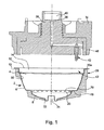
図1及び図2は飲料を調製する装置1を示し、図1は解離した状態、図2は結合した状態を示している。装置1内では、可溶性及び/又は浸出性の食品4(図示せず)、例えば、炒って挽いたコーヒー、茶、可溶性コーヒー、挽いたコーヒーと可溶性コーヒーとの混合物、チョコレート製品、その他の乾燥物質を入れたカプセル2に加圧噴射液体を、通常は温水又は冷水を通すことにより飲料が調製される。
1 and 2 show an apparatus 1 for preparing a beverage, FIG. 1 shows a dissociated state, and FIG. 2 shows a joined state. Within the apparatus 1 soluble and / or leachable food 4 (not shown), for example roast and ground coffee, tea, soluble coffee, a mixture of ground and soluble coffee, chocolate products, other dry substances A beverage is prepared by passing a pressurized jetting liquid through the
図1にも見られるように、カプセル2は、側壁6と底部を形成する底壁8とを備えた事実上小型のカップの形状を有している。図示の実施例では、底壁8の直径はカップの口の直径より小さい。側壁6の自由端部は、カップの外方へ延びる事実上環状の周縁リム10で終わっている。側壁6と底壁8とは、通常、例えば、EVOH,PVDC,PP,PE,PAを含む群の中から選択した単層又は多層のプラスチック材料から成っている。カップは、例えば熱接着によりリム10に結合されたカバーから成る頂壁12により密閉されている。
As can also be seen in FIG. 1, the
頂壁12は、通常、装置1の、後述する穴あけ兼噴射部材によって穴あけ可能な材料で作られる。頂壁12の材料は、例えばアルミニウム、アルミニウム/プラスチック複合材料、厚紙/プラスチック合材、厚紙/アルミニウム/プラスチック合材、単層又は多層のプラスチックを含む群から選択できよう。したがって、側壁6、底壁8、頂壁12は一緒に食品物質4を内包するチャンバ14を形成している。もちろん、カプセル2は、開放カプセル又は部分開放カプセルであっても、同じように満足のゆくものとなろう。より一般的な意味では、「カプセル」という用語は、その形状又は構成材料に関する制限なしに、広く物質を内包する何らかの交換可能な種類の容器を指している。
The
図示の実施例の場合、カプセル2の下部セグメントには、カップの内側リムに密着し、チャンバ14の下部を閉じる薄手のフィルム16が組み付けられている。この薄手のフィルム16は、均等に間隔をおいた多数の突起を上面に有するディスク20の頂部に配置され、該突起が、ディスクの周部と捕集チャンバ22とへ通じる多数の通路を形成し、該捕集チャンバは、ディスク20と底部8とにより境界付けられ、チャンバ自体は出口24を介して外部へ開放されている。薄手のフィルム16は、チャンバ14内で圧力を受けて突起と接触することで破断される。図に見られるように、出口は、カプセル2と一体であり、そのことの利点は、装置に直接接触することなく飲料をコップ類に直接放出できることであり、それによって、飲料の接触汚染が防止され、より衛生的になり、洗浄が少なくて済み、装置自体の設計も、より簡単になる。カプセル2のより詳しい説明は、本出願人名で2003年1月13日に申請されたヨーロッパ特許出願PCT第03/00384号に記載されており、その全内容の一部がここに引用されている。
In the illustrated embodiment, a
装置1は、概して円筒形のカプセルホールダ28上に配置される概して円筒形の液体噴射ヘッド26を有している。噴射ヘッド26とカプセルホールダ28とは、カプセル2がホールダ28上に配置される前の解離位置(図1)と、装置1が働き得る結合位置(図2)との間で、互いに垂直方向に移動可能である。
より詳しく言えば、カプセル2はカプセルホールダ内の保持部30内に配置されており、保持部の形状は、通常、受容されるカプセルの形状と相補的に合致している。保持部30の下部には、カプセル2の出口と整合する開口32が設けられている。カプセルホールダは、したがって装置1内でカプセル2の支持部をなしている。
The apparatus 1 has a generally cylindrical
More specifically, the
噴射ヘッド26は、事実上鐘形の保持体34を含み、該保持体の開口部34aには中心軸36が配置されている。中心軸36は、液体取り入れ通路38を含み、該通路が、液体送入溜め40と、噴射口42aを有する穴あけ兼噴射部材42との間に延びている。詳しくは後述するが、調製装置が結合位置に置かれることで噴射ヘッド26とカプセルホールダ28とが相対運動し、それにより穴あけ兼噴射部材42が、頂壁12を貫通して噴射口42aをカプセル内部と接続するのに役立つ。
液体送入溜め40は、加圧された温水又は冷水を供給可能な装置(図示せず)からの液体給送管に接続するように設計されている。噴射ヘッド26は噴射組み立て体を構成しており、該組み立て体は、ジェットスプレーJの形式の液体を穴あけ兼噴射部材42の噴射口42aで形成された少なくとも1つの噴射箇所から噴射することができる。
図示の実施例では、開口部34aは、事実上円筒形であり、その底面34bは中心孔44を有し、該中心孔が雌ねじを有するスリーブ46を貫通して軸方向に外方へ延びている。
The
The
In the illustrated embodiment, the opening 34a is substantially cylindrical and its
中心軸36は、開口部34a内に延びる大直径の円筒形第1セグメントと、スリーブ46内へねじ付けられた小直径の第2セグメントとを含んでいる。噴射ヘッド26は、また中心軸36の第1セグメントと開口部34aの内壁との間に配置された環状ガスケット48を含んでいる。ガスケット48は、結合位置(図2)では、カプセルのリム10に押し付けられ、該リムは、またカプセルホールダ28の周方向の上部支持面28a上に載置される。ガスケット48は、また開口部34aから軸方向に突出し、リムと接触するさい適当に圧縮されることで、良好なシールが得られる。図示の実施例では、ガスケット48が、穴あけ兼噴射部材42の区域で液体取り入れ通路38をもシールしているのが分かる。
The
図3は、頂壁12を除去したカプセル2の平面図で、噴射ヘッド26の穴あけ兼噴射部材42のみを示したものだが、この図を見ると、穴あけ兼噴射部材42が、より詳しく言えば、噴射口42aが、カプセル2の中心Cから距離をおいて位置しており、したがって、カプセルの垂直軸線A−Aから外れて位置していることが分かる。噴射口42aの軸線50は、一端がカプセル2の中心C(図3)のそばを通る第1方向に、他端は、カプセルの底部に向かう第2方向(図2)に配向されている。カプセル内での噴射口42aのこの位置構成と、該噴射口の軸線50の特定の配向とによって、液体の噴射は、そのジェットスプレーによりカプセルの中心の周囲に渦乱流を生じさせ、同時にカプセル内壁にジェットスプレーが何度も跳ね返される。噴射液体の全体的な渦運動が何度にもわたる跳ね返りと組み合わされて、液体が物質4とくまなく混合され、完全に物質に浸透する。
FIG. 3 is a plan view of the
このような混合の成果を得るためには、つまりカプセル2内に最適渦流効果を生じさせるためには、出願人は、噴射口42aの軸線50の一部が、噴射箇所とカプセル2の中心Cとを結ぶ線52に対して20°〜60°、好ましくは35°〜45°の角度αを必要とすること、かつまた軸線50が、カプセルの垂直軸線A−Aに対し50°〜70°、好ましくは55°〜65°の角度βでなければならないことを発見した。また、噴射口42aは、物質がカプセルの周辺から中心へ向かって漸次加湿され、確実に全物質が液体と接触するように、カプセルの側壁6の近くに位置するのが好ましい。一例として、噴射口42aの直径は約0.7mmであり、液体の噴射率は約4ml/sである。
In order to obtain such a mixing result, that is, in order to produce an optimum eddy current effect in the
図4は、穴あけ兼噴射部材42の一実施例の断面図で、該部在は、調製装置が結合位置にある場合に、頂壁12に穴をあけ貫通して延びるようにするのに役立つ。穴あけ兼噴射部材42は、両端部が開放された通路42bを有する中空ピンを含んでいる。第1端部は、液体取り入れ通路38に接続され、第2端部は噴射口42aを介して外部に通じている。通路42bは、直線的な第1部分と、噴射口42aで終わり、該第1部分と或る角度をなして延びる第2部分とを含んでいる。通路の第2部分の傾斜は、カプセル内へ液体が噴射される角度と等しく、第1部分は、中空ピンが中心軸36内に配置される場合、軸線A−Aと事実上平行に延在する。図4からはまた、穴あけ兼噴射部材42として構成された中空ピンが、その遠位端にベベル42cを有し、噴射口42aが、ベベル42cとは反対側の面に通じていることが分かる。中空ピン遠位端のこの特殊な構成により、中空ピン42が頂壁12を貫通する場合、頂壁12の穴あけされた部分が噴射口とは反対側へ押し出されることで、噴射口は、常に完全に開口し、頂壁12の穴あけされた部分がカプセル内への液体の噴射を妨害することがない。
FIG. 4 is a cross-sectional view of one embodiment of the piercing and
図示されていない設計の変化形によれば、穴あけ兼噴射部材42の周囲にシールを備えて、調製装置が作業状態にあるときに、チャンバが外部から密閉された状態を保つようにすることができる。
もちろん、噴射口42aの位置は、液体の噴射が頂壁12の数ミリメートル下方で、通常は4mm下で行われるように設定されている。
According to a design variant not shown, a seal is provided around the drilling and
Of course, the position of the
図5は、本発明によるカプセル内にくまなく液体を噴射し、飲料を調製する装置1の設計の変化形の斜視図で、噴射ヘッドのみを示したものである。この設計変化形では、カプセルホールダは、図1及び図2に示したものと等しいが、噴射ヘッド26は、穴あけ兼噴射部材42を1個だけではなく、数個、この場合は3個を含み、すべて等しい設計であり、図1から図4に関連して説明した穴あけ兼噴射部材42と配向が等しい。図に見られるように、3個の穴あけ兼噴射部材42が均一の間隔を置いて噴射ヘッド26の下面に配置され、調製装置が作業状態にある場合に、カプセル2の頂壁12上で作業するのに役立つ。通常、これらの部材42は、噴射ヘッド26を中心として、その周囲に互いに120°の間隔をおいて配置される。この場合は、取り入れ通路38が、言うまでもなく、3個の穴あけ兼噴射部材42の各々に接続されるように設計されている。
FIG. 5 is a perspective view of a variant of the design of the device 1 for jetting liquid all over the capsule according to the invention and preparing a beverage, showing only the jet head. In this design variant, the capsule holder is the same as that shown in FIGS. 1 and 2, but the
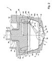
図6及び図7は、本発明によるカプセル内にくまなく液体を噴射して飲料を調製する装置の実施例の第2形式を示している。調製装置は、両図面とも結合位置で示してあるが、図6では第1機能モードで、図7では第2機能モードで示されている。本発明の目的の場合、機能モードという用語は、カプセル2に入れられた物質を加湿する所要の形式を言い、そのモードは、事実上、使用する物質によって決まる。
図6は、第1加湿モードでの調製装置を示し、この場合、液体がカプセル内へ噴射されることで、図1各々図2について説明したように、カプセルの中心Cの周囲に液体の渦運動が発生し、ジェットスプレーの内壁への何度もの跳ね返りと組み合わされる。この浸透モードは、溶解可能な物質入りのカプセルに最適であり、その理由は、このモードでは、可溶性の物質が完全かつ迅速に溶解できるからである。
6 and 7 show a second form of embodiment of the device for preparing a beverage by spraying a liquid all over the capsule according to the invention. The preparation device is shown in the combined position in both figures, but is shown in the first function mode in FIG. 6 and in the second function mode in FIG. For the purposes of the present invention, the term functional mode refers to the required form of humidifying the substance placed in the
FIG. 6 shows the preparation device in the first humidification mode, in which the liquid is injected into the capsule, so that the liquid vortex around the center C of the capsule, as described for FIG. 1 and FIG. Movement occurs and is combined with multiple rebounds to the inner wall of the jet spray. This penetration mode is optimal for capsules with dissolvable substances, since in this mode soluble substances can be completely and rapidly dissolved.
図7には第2加湿モードで調製装置が示され、この場合は、液体がカプセル内へ噴射されることによって、カプセルの中心Cの周囲に液体の渦乱流が生じるのに加えて、カプセルの上部が、薄いシートの形式で液体の幾らかを分岐させた噴射液体により浸され、カプセル内の物質が上方からも加湿される。この浸透モードが特に有用なのは、浸出可能な物質入りのカプセルの場合であり、理由は、このモードでは、その種の物質の完全かつ迅速な溶解(sic原文のまま)が可能だからである。 FIG. 7 shows the preparation device in the second humidification mode, in which the liquid is injected into the capsule, in addition to the vortex flow of the liquid around the center C of the capsule, The upper part of the capsule is soaked by a jet liquid that diverges some of the liquid in the form of a thin sheet, and the substance in the capsule is also humidified from above. This penetration mode is particularly useful for capsules with leachable substances, since this mode allows complete and rapid dissolution of that kind of substance (sic original).
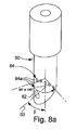
本発明のこの第2実施形式によれば、調製装置は、図1から図4に関連して説明した穴あけ兼噴射部材42の噴射口42aと等しい形式で位置決めされ配向された第1噴射口62と、液体の薄手のシート形式での分岐流を発生させるために事実上水平方向に噴射軸線が延びている第2噴射ユニット64とを備えた穴あけ兼噴射部材60を含んでいる。図8a及び図8bの双方から分かるように、図示の例では、穴あけ兼噴射部材60は、通路60bを有する中空ピンの形式であり、該通路は、第1と第2の噴射ユニット62,64各々を介して第1端部から外部へ通じている。通路60bは、またその中間区間で開口66を介して取り入れ通路38と接続されている。
According to this second embodiment of the invention, the preparation device comprises a
穴あけ兼噴射部材は、噴射ユニット62,64とは反対側の端部が、ヘッド26に結合されたスイッチ部材(図示せず)により制御されたレバー68と協働するカム60cと接触している。穴あけ兼噴射部材60は、開口66が設けられた拡径部を中間区域に含み、該拡径部により、肩を備えたトラック70内で並進運動が可能になるように組み付けられ、該トラックは、中心軸36に固定された噴射ヘッドの垂直軸線と平行に延び、引き戻しばね72が、トラック底部と穴あけ兼噴射部材62の一方の肩との間に配置されている。穴あけ兼噴射部材60の開口66の両側に2個のOリング・ガスケットが配置され、トラック70の内面に接触している。
The end of the drilling and injection member opposite to the
この実施形式の場合、穴あけ兼噴射部材60は2つの異なる位置の間を移動できる。すなわち、第1噴射口62だけをカプセル2の内部へ連通させ、かつ第1加湿モードに対応する第1位置と、第1噴射口62と第2噴射ユニット64とをカプセル2の内部へ連通させ、かつ第2加湿モードに対応する第2位置との間を移動できる。第1加湿モードから第2加湿モードへの切り替えは、スイッチ部材を介して行われ、該スイッチ部材は、穴あけ兼噴射部材60を引き戻しばねの作用によりレバー68を介して変位させる。もちろん、取り入れ通路38の直径と、開口66の直径と、第1加湿モードから第2加湿モードへの切り替えの場合の穴あけ兼噴射部材の経路とは、開口66が、選択されたモードに関係なく、少なくとも部分的に取り入れ通路38と常時連通するように構成されている。
In this embodiment, the drilling and
図8a及び図8bから明らかなように、液体の薄手のシート形式の分岐流を発生させる第2噴射ユニット64は、穴あけ兼噴射部材60の周部に分配された数個の噴射口64aを含むのが好ましい。穴あけ兼噴射部材60は、カプセル内で中心を外れて、より詳しく言えばカプセルの側壁近くに配置されているが、噴射口64aは、カプセルの中心へ向けられている。穴あけ兼噴射部材60の製造に関連する理由のため、噴射口64aは互いに高さを互い違いにするのが好ましい。これらの噴射口64aは、カプセル上部に位置する物質に液体を浸透させ飽和させる薄手の液体シートの形にまとまる数個の分岐流を生じさせる。
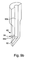
もちろん、薄手の液体シートは、図9a及び図9bに示すように、穴あけ兼噴射部材60の長手方向に対し横方向に延びるスリットの形式の単一の噴射口64bによって形成することも考えられる。その場合には、分岐流は、カプセル上部の事実上全物質に浸透するのに十分な大きさの円形区域にわたって拡散する。
As is apparent from FIGS. 8 a and 8 b, the
Of course, it is conceivable that the thin liquid sheet is formed by a
言うまでもないことだろうが、噴射口64a,64bは、90°〜180°の、好ましくは約160°の角度範囲にわたって事実上連続的な薄手の液体シートを発生させるように、各々が配置されている。更に、これらの噴射口64a,64bは、0.5mm以下の厚さ、好ましくは0.3mm未満の厚さの液体シートを形成するように設計されている。その目的のために、噴射口64aに選択した直径は、好ましくは約0.5マイクロメートル、噴射口64bに選択した縦幅は約0.7mmである。
第2実施形式の有利な一変化形の場合、第2噴射ユニット64の軸線、つまり、それぞれ液体のスプレー方向を決定する噴射口64a,64bの軸線は、水平面に対し0°〜25°の角度、好ましくは約15°の角度をなしている。これらの噴射口から噴射される液体は、したがって上向きであり、最初に頂壁12の下面に当たって跳ね返った後、第2段階で、事実上より拡散した形で物質の大部分へ向かって送り戻され、更に物質への液体の均一な浸透が促進される。
Needless to say, the
In the case of an advantageous variant of the second embodiment, the axis of the
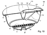
図10は、加圧液体を噴射することにより飲料を調製するための、可溶性及び/又は浸出性食品4を内包するカプセル100を示し、該カプセルは、本発明の方法を実施するのに好適なものであり、単一の液体分配ノズルを有する従来式の装置を備えている。その意味で、カプセル100は、図1及び図2について説明したカプセル2とは異なり、頂壁110が、単一のジェットスプレーJによりチャンバ14内へ液体を噴射するように構成された噴射組み立て体112を含み、前記噴射箇所と前記ジェットスプレーJの方向とは、前記カプセル内に渦乱流が発生し、液体が前記物質と混合するように選択されている。
より詳しく言えば、頂壁110は外壁部材114と内壁部材116を包含し、両部材が共同でキャビティ118を画成しており、該キャビティは外部に対してシールされ、通路120は、キャビティ118を噴射組み立て体112と連通させている。
FIG. 10 shows a
More specifically, the
外壁部材114はカバーの形式であり、該カバーが、穴あけ兼噴射部材(図示せず)、例えば従来式の飲料調製装置の噴射ノズル等によって穴あけ可能な少なくとも1つの材料区域を含んでいる。図示の例では、外壁部材114は、カプセルのリムに熱接着されたカバーであり、このカバーの構造は、図1及び図2との関連で説明したカバー12の構造と等しい。
この実施形式では、キャビティ118と通路120とは、特定の深さレベルで直接に内壁部材16に凹部として設けられ、キャビティ118は、カプセルの事実上中心に形成されている。キャビティ118は、従来型の調製装置の穴あけ兼噴射部材を受容するように設計されているので、その位置と深さとは、言うまでもなく、一緒に使用される装置の機能に応じて変更できる。
The
In this implementation, the
内壁部材116は、また噴射ノズル112aから成る噴射組み立て体112を含んでいる。好ましくは、図示のように、噴射ノズル112aは、内壁部材116と一体の部分を形成している。噴射ノズル112aは、噴射口112bを含み、該噴射口は、図1から図4に関連して説明した穴あけ兼噴射部材42の噴射口42aと同じように配置され配向されている。
本発明によるカプセルの設計の一変化形(図示せず)では、噴射ノズルが、事実上水平方向の噴射軸線を備えた複数の第2噴射部材をも有しており、この第2噴射部材が、薄手の液体シートの形式の第2分岐流を発生させる。これらの第2噴射部材は、通常、図8a及び図9aに関連して説明したような多数の噴射口又は単一のスリットから構成できよう。
In a variant of the capsule design according to the invention (not shown), the injection nozzle also has a plurality of second injection members with a substantially horizontal injection axis, which second injection members A second branch flow in the form of a thin liquid sheet is generated. These second injection members could typically consist of a number of injection ports or a single slit as described in connection with FIGS. 8a and 9a.
以下で、可溶性食品入りのカプセル内へくまなく液体を噴射することによって飲料を調製する本発明の方法を、図1及び図2に示した本発明の装置の第1実施例を用いて説明する。まず、装置が解離位置(図1)にあるときに、カプセル2をカプセルホールダ28内に配置する。次いで、カプセルホールダ28と噴射ヘッド26との垂直方向相互運動により、装置を結合する(図2)。これにより、カプセルのリム10が、ガスケット48の下部環状面とカプセルホールダの上部支持面28aとの間にクランプされる。同時に、カバー12に穴あけ兼噴射部材42が穴あけする。この構成の場合、噴射口42は、カプセル2の内部で好ましくはカバーの数ミリメートル下に位置させられる。
In the following, the method of the present invention for preparing a beverage by spraying a liquid all the way into a capsule containing soluble food will be described using the first embodiment of the device of the present invention shown in FIGS. . First, the
次いで、飲料を調製するのに使用される液体、例えば熱湯がカプセル内に加圧噴射されるが、その場合、液体は、第1段階で、溶解対象の物質が漸次溶解されるように配向された噴射口42aから、中心のそばを通り過ぎる方向で、カプセルの一方の壁に向かって或る角度で噴射され、該カプセル壁までトンネルを掘り進める。前記カプセル壁に到達して、ジェットスプレー及びその運動エネルギーに方向が与えられると、スプレーは、方向を転じて物質を溶解し続けながら、再び別の壁に到達し、こうしてカプセルの中心の周囲に噴射液の渦運動を発生させる。この渦乱流が、液体を物質と混合し、物質の完全溶解が可能になる。同時に、カプセル内圧が徐々に上昇し、図1及び図2に示したディスク20の突起周囲のダイアフラムが漸次膨張する。圧力上昇の結果、ダイアフラム16の破壊張力に達すると、直ちにダイアフラムは破断し、溶解液はカプセル2の出口24から流出できる。渦噴流の跳ね返りは、物質の残りの全量が完全に溶解するまで続く。
The liquid used to prepare the beverage, for example hot water, is then injected into the capsule under pressure, in which case the liquid is oriented in a first stage so that the substance to be dissolved is gradually dissolved. From the
図6及び図7に示した本発明による装置の第2実施形式を用いて、抽出型の、すなわち浸出性の食品入りのカプセル内にくまなく液体を噴射することで飲料を調製する場合は、本発明による方法は、装置が、最初にカプセル入り物質に対応して加湿モード,この場合は図7に示した第2加湿モードに切り替えられる点で既述の方法とは異なっている。この第2加湿モードでは、付加的に噴射ユニット64を介して上方から物質が加湿されるように、1個から数個の薄手の液体シート形式でカプセル上部への液体噴射が誘発される。出願人は、噴射ジェットJと薄手の液体シートとの組み合わせで物質を加湿するのが、浸出性物質から飲料を調製するさいには、特に効果的であることを発見した。
Using the second embodiment of the device according to the invention shown in FIGS. 6 and 7 to prepare a beverage by spraying a liquid all the way into an extractable, ie leachable food-filled capsule, The method according to the invention differs from the previously described method in that the device is first switched to the humidification mode corresponding to the encapsulated substance, in this case the second humidification mode shown in FIG. In this second humidification mode, liquid injection is induced on the top of the capsule in the form of one to several thin liquid sheets so that the substance is additionally humidified from above via the
図10に示したカプセル100の場合、従来型の穴あけ兼噴射部材を備えた装置を用いて本発明の調製方法を実施することができる。実際に必要なことは、カプセル100が装置内に配置された場合に、キャビティ118の位置が装置の穴あけ兼噴射部材に整合するようにし、カバー110に穴があけられた瞬間に穴あけ兼噴射部材がキャビティ118内へ貫通できるようにすることだけである。その場合、噴射液体はキャビティを満たし、通路120を通って噴射口112aに達し、噴射口から圧力を受けてカプセル内へ噴射され、既述の経過が得られる。
In the case of the
言うまでもなく、本発明は、既述の実施例に限定されるわけではなく、当業者には、特許請求の範囲に定義された本発明の趣旨を逸脱することなしに種々の変更態様及び/又は強化が可能なことが理解されよう。特に、変化形に関しては、液体のジェットスプレーがカプセルの中心Cの周囲に渦運動を発生させ、液体をカプセル内の物質と混合できるように、穴あけ部材が配置され配向されるかぎりにおいて、穴あけをカバー12にではなく、カプセルの他の壁に行う設計も考えられる。例えば、穴あけ兼噴射部材は、カプセルの側壁又は底壁さえをも貫通するようにすることができよう。
略号
EVOH:copolymer of ethylene and vinyl alkohl
PVDC:Vinylidene polychloride
PP:Polypropylene
PE:Polyethylene
PA:Polyamide
Needless to say, the present invention is not limited to the above-described embodiments, and various modifications and / or modifications will be apparent to those skilled in the art without departing from the spirit of the invention as defined in the claims. It will be understood that enhancements are possible. In particular, as regards the variation, as long as the piercing member is positioned and oriented so that the liquid jet spray can generate vortex motion around the center C of the capsule and mix the liquid with the material in the capsule, the piercing is performed. Designs on the other wall of the capsule rather than on the
Abbreviation EVOH: copolymer of ethylene and vinyl alkhol
PVDC: Vinylidene polychloride
PP: Polypropylene
PE: Polyethylene
PA: Polyamide
1 調製装置
2,100 カプセル
4 食物
6 カプセルの側壁
8 カプセルの底壁
10 環状リム
12,110 カプセルの頂壁(カバー)
14 チャンバ
16 薄手のフィルム(ダイアフラム)
18 内側リム
20 ディスク
22 捕集チャンバ
24 出口
26 液体噴射ヘッド
28 カプセルホールダ
30 保持部
32 開口
34 支持体
34a 開口部
34b 底面
36 中心軸
38 液体取り入れ通路
40 液体流入溜め
42,60 穴あけ兼噴射部材
42a 噴射口
44 中心孔
46 スリーブ
48 ガスケット
50 噴射口の軸線
60b 通路
60c カム
62 第1噴射口
64 第2噴射ユニット
64a 数個の噴射口
64b 単一噴射口
66 開口
68 レバー
70 トラック
72 引き戻しばね
112 噴射組み立て体
112a 噴射ノズル
112b 噴射口
114 外壁部材
116 内壁部材
118 キャビティ
120 通路
EVOH エチレン及びビニルアルコールの共重合体
PVDC ポリ塩化ビニリデン
PP ポリプロピレン
PE ポリエチレン
PA ポリアミド
DESCRIPTION OF SYMBOLS 1 Preparation apparatus 2,100 Capsule 4 Food 6 Capsule side wall 8
14
18 Inner rim 20 Disc 22
Claims (33)
前記液体が、少なくとも1つの噴射箇所から噴射されることで、前記入れ物内に噴射液体の渦運動が発生して前記液体が前記物質と混合される、飲料を調製する方法。 In a method of preparing a beverage by spraying a liquid into a container containing a soluble and / or extractable food,
A method of preparing a beverage, wherein the liquid is jetted from at least one jetting location, thereby generating a vortex motion of the jetted liquid in the container and mixing the liquid with the substance.
前記噴射箇所と前記ジェットスプレーの方向とが、前記液体と前記食物とを混合させる渦乱流を前記カプセル内に発生させるように構成されていることを特徴とする、飲料を調製する装置。 An apparatus for preparing a beverage by spraying a liquid all over a capsule containing a substance to be dissolved or extracted, the apparatus comprising means for supporting the capsule and at least one spray point into the capsule In the form of having at least one liquid ejection assembly designed to eject liquid in the form of a jet spray;
A device for preparing a beverage, characterized in that the spray location and the direction of the jet spray are configured to generate a vortex flow in the capsule that mixes the liquid and the food.
前記第1噴射口がカプセルの中心から距離をおいて配置され、前記第1噴射口の軸線が前記中心のそばを通り過ぎる方向に延びていることを特徴とする、請求項13に記載された装置。 14. The apparatus of claim 13, wherein the capsule has a center and the injection assembly includes at least one drilling and injection member with a first injection port.
14. A device according to claim 13, characterized in that the first injection port is arranged at a distance from the center of the capsule and the axis of the first injection port extends in a direction passing near the center. .
前記頂壁が、少なくとも1噴射箇所からチャンバ内へジェットスプレー形式の前記液体を噴射するように構成された噴射組み立て体を含み、前記噴射箇所とジェットスプレーとが、前記液体を前記物質と混合させる渦運動をカプセル内に発生させるように構成されていることを特徴とする、可溶性及び/又は抽出可能な食物を内包するカプセル。 Capsule containing soluble and / or extractable food for preparing a beverage by spraying a liquid under pressure, comprising a top wall and a bottom wall, both of which are joined by a side wall In a type in which a chamber containing the substance is defined by
The top wall includes an injection assembly configured to inject the liquid in a jet spray form into the chamber from at least one injection point, the injection point and the jet spray mixing the liquid with the substance. Capsule containing soluble and / or extractable food, characterized in that it is configured to generate vortex motion within the capsule.
Applications Claiming Priority (2)
| Application Number | Priority Date | Filing Date | Title |
|---|---|---|---|
| EP03019163A EP1510159A1 (en) | 2003-08-25 | 2003-08-25 | Procedure for making a food product |
| PCT/EP2004/009125 WO2005020769A1 (en) | 2003-08-25 | 2004-08-13 | Methods and device for the preparation of a food product |
Publications (1)
| Publication Number | Publication Date |
|---|---|
| JP2007503233A true JP2007503233A (en) | 2007-02-22 |
Family
ID=34089598
Family Applications (1)
| Application Number | Title | Priority Date | Filing Date |
|---|---|---|---|
| JP2006524280A Pending JP2007503233A (en) | 2003-08-25 | 2004-08-13 | How to prepare food |
Country Status (16)
| Country | Link |
|---|---|
| US (1) | US20070144355A1 (en) |
| EP (2) | EP1510159A1 (en) |
| JP (1) | JP2007503233A (en) |
| CN (1) | CN100522020C (en) |
| AR (1) | AR047215A1 (en) |
| AT (1) | ATE410941T1 (en) |
| AU (1) | AU2004267931B2 (en) |
| CA (1) | CA2536750C (en) |
| DE (1) | DE602004017191D1 (en) |
| ES (1) | ES2314433T3 (en) |
| HK (1) | HK1090527A1 (en) |
| MY (1) | MY140765A (en) |
| NZ (1) | NZ545928A (en) |
| PT (1) | PT1659909E (en) |
| TW (1) | TWI277402B (en) |
| WO (1) | WO2005020769A1 (en) |
Cited By (9)
| Publication number | Priority date | Publication date | Assignee | Title |
|---|---|---|---|---|
| JP2008503285A (en) * | 2004-06-25 | 2008-02-07 | ネステク ソシエテ アノニム | Method for improving foam generation during preparation of a beverage from a cartridge and apparatus for carrying out the method |
| JP2011506014A (en) * | 2007-12-18 | 2011-03-03 | ネステク ソシエテ アノニム | Beverage preparation device comprising a detachable injection member |
| JP2012510323A (en) * | 2008-12-03 | 2012-05-10 | ネステク ソシエテ アノニム | Capsules for the preparation of beverages by centrifugation |
| KR101419889B1 (en) * | 2012-11-05 | 2014-07-15 | 정휘동 | Apparatus of extracting beverage from capsule containing raw material for beverage |
| KR20140096142A (en) * | 2011-11-25 | 2014-08-04 | 조영 컴퍼니 리미티드 | Soybean milk preparation method of soybean milk preparation equipment |
| JP2017512535A (en) * | 2014-03-12 | 2017-05-25 | サロング ソシエタ ペル アツィオニ | Beverage capsule |
| JP2017513543A (en) * | 2014-03-13 | 2017-06-01 | パンゲア ラブス リミテッド | Compound beverage supply device |
| KR20190071831A (en) * | 2011-11-23 | 2019-06-24 | 스타벅스 코포레이션 | Apparatus, systems, and methods for brewing a beverage |
| US11013362B2 (en) | 2013-11-20 | 2021-05-25 | Starbucks Corporation | Apparatuses, systems, and methods for brewing a beverage |
Families Citing this family (72)
| Publication number | Priority date | Publication date | Assignee | Title |
|---|---|---|---|---|
| ITPN20020090A1 (en) * | 2002-11-21 | 2004-05-22 | Necta Vending Solutions Spa | CAPSULE FEEDING APPARATUS FOR DISTRIBUTORS |
| JP4879898B2 (en) | 2004-08-23 | 2012-02-22 | ネステク ソシエテ アノニム | Capsules that prepare and distribute beverages by injecting pressurized fluid into the capsules |
| MX2007003792A (en) * | 2004-10-01 | 2007-07-11 | Hausbrandt Trieste 1892 Spa | Apparatus and method for preparing and delivering a beverage with the use of a raw matter contained in a cartridge. |
| EP1792849A1 (en) * | 2005-12-02 | 2007-06-06 | Tuttoespresso S.p.a. | Pressure beverage cartridge and preparation method |
| DE102005061927A1 (en) * | 2005-12-23 | 2007-06-28 | BSH Bosch und Siemens Hausgeräte GmbH | Shapely pad |
| ATE505984T1 (en) * | 2006-03-28 | 2011-05-15 | Tuttoespresso Srl | METHOD AND DEVICE FOR PREPARING A DRINK UNDER CONTROLLED PRESSURE |
| PT2029457E (en) * | 2006-05-29 | 2010-05-21 | Nestec Sa | Coffee capsule with a deformable sealing element |
| EP1932457A1 (en) | 2006-12-11 | 2008-06-18 | Nestec S.A. | Device and method for producing a frothed liquid from soluble ingredients and diluent |
| DE602007001147D1 (en) * | 2007-03-06 | 2009-07-02 | Nestec Sa | System for making a beverage from a capsule and method |
| EP1975087B2 (en) | 2007-03-19 | 2018-05-16 | Nestec S.A. | Capsule with flow regulating technology |
| US8986764B2 (en) * | 2007-06-05 | 2015-03-24 | Nestec S.A. | Capsule and method for preparing a food liquid by centrifugation |
| US10722066B2 (en) * | 2010-12-04 | 2020-07-28 | Adrian Rivera | Windowed single serving brewing material holder |
| US11832755B2 (en) * | 2007-07-13 | 2023-12-05 | Adrian Rivera | Brewing material container for a beverage brewer |
| GB2454656A (en) | 2007-11-09 | 2009-05-20 | Kraft Foods R & D Inc | A beverage cartridge |
| DK2080454T3 (en) * | 2008-01-18 | 2010-11-22 | Nestec Sa | Beverage machine and piercing member for an opening device of a beverage machine |
| EP2238050B1 (en) * | 2008-02-06 | 2011-04-20 | Nestec S.A. | Labyrinth capsule for drink powder |
| RU2484750C2 (en) * | 2008-03-20 | 2013-06-20 | Нестек С.А. | Device for preparation of beverage of disposable capsule |
| IT1390883B1 (en) | 2008-07-31 | 2011-10-19 | Cometto | GROUP OF DRINKS FOR DRINKS |
| US8227000B2 (en) * | 2008-12-18 | 2012-07-24 | Whirlpool Corporation | Liquid flow control and beverage preparation apparatuses, methods and systems |
| US8468935B2 (en) * | 2008-12-18 | 2013-06-25 | Whirlpool Corporation | Liquid flow control and beverage preparation apparatuses, methods and systems |
| US8133525B2 (en) * | 2008-12-18 | 2012-03-13 | Whirlpool Corporation | Liquid flow control and beverage preparation apparatuses, methods and systems |
| US8166868B2 (en) * | 2008-12-18 | 2012-05-01 | Whirlpool Corporation | Liquid flow control and beverage preparation apparatus |
| US8221811B2 (en) * | 2008-12-18 | 2012-07-17 | Whirlpool Corporation | Liquid flow control and beverage preparation apparatuses, methods and systems |
| US8215228B2 (en) * | 2008-12-18 | 2012-07-10 | Whirlpool Corporation | Liquid flow control and beverage preparation for a refrigerator |
| US8166867B2 (en) * | 2008-12-18 | 2012-05-01 | Whirlpool Corporation | Liquid flow control through a beverage preparation apparatus |
| US8272318B2 (en) * | 2008-12-18 | 2012-09-25 | Whirlpool Corporation | Liquid flow control and beverage preparation apparatuses, methods and systems |
| US8297180B2 (en) * | 2008-12-18 | 2012-10-30 | Whirlpool Corporation | Liquid flow control and beverage preparation apparatuses, methods and systems |
| US20110271841A1 (en) * | 2009-01-13 | 2011-11-10 | Nestec S.A. | Injection assembly and machine for preparing a drink provided with this injection assembly |
| PT2236437E (en) * | 2009-03-31 | 2012-04-13 | Nestec Sa | Capsule with filter for preparing a liquid nutritional or food composition and related beverage production system |
| SA110310345B1 (en) | 2009-05-05 | 2013-12-30 | Nestec Sa | Capsule for Preparing a Nutritional Product Including a Water Filter |
| SG175793A1 (en) | 2009-05-05 | 2011-12-29 | Nestec Sa | Capsule for preparing a nutritional product including a filter |
| PL2427067T3 (en) * | 2009-05-05 | 2013-05-31 | Nestec Sa | Capsule for preparing a nutritional product including a filter and method |
| RU2690280C2 (en) * | 2009-06-17 | 2019-05-31 | Конинклейке Дауве Егбертс Б.В. | System, capsule and beverage preparation method |
| DE102009049945A1 (en) * | 2009-10-19 | 2011-04-21 | Krüger Gmbh & Co. Kg | Brewing device and method for extracting a portion capsule |
| US9084511B2 (en) | 2009-10-22 | 2015-07-21 | Bunn-O-Matic Corporation | Flexible spray head |
| PT2404844E (en) | 2010-07-07 | 2012-10-11 | Nestec Sa | A capsule for preparation of a food product from a food preparation machine |
| PL3521208T3 (en) | 2010-07-22 | 2020-08-10 | K-Fee System Gmbh | Portion capsule with barcode |
| EP2409931A1 (en) * | 2010-07-22 | 2012-01-25 | Nestec S.A. | A capsule for the preparation of a food product in a food preparation machine at high pressure |
| PL2637951T3 (en) * | 2010-11-11 | 2016-08-31 | Nestec Sa | Capsule and system for the preparation of a nutritional product |
| MA34895B1 (en) | 2011-02-16 | 2014-02-01 | Nestec Sa | CONTAINER FOR PREPARING BEVERAGE COMPRISING AN IMPROVED PERCEABLE SHEET AND PROCESS FOR PREPARING A BEVERAGE |
| PT105598B (en) | 2011-03-30 | 2020-01-17 | Novadelta Comercio E Ind De Cafes Lda | CONTROLLED OPENING CAPSULE, PROCESS AND OPERATING DEVICE OF THIS CAPSULE |
| EP2583659B1 (en) * | 2011-10-17 | 2015-09-16 | Nestec S.A. | Expandable container for preparation of a nutritional composition |
| AT512630A1 (en) * | 2012-03-09 | 2013-09-15 | Modl | portion capsule |
| ITTO20120724A1 (en) * | 2012-08-13 | 2014-02-14 | Lavazza Luigi Spa | SEALED CAPSULE FOR THE PREPARATION OF A BEVERAGE, IN PARTICULAR COFFEE |
| ITVR20130285A1 (en) * | 2013-12-17 | 2015-06-18 | Caffita System Spa | CAPSULE FOR THE PREPARATION OF DRINKS |
| US9278801B2 (en) * | 2013-12-18 | 2016-03-08 | Robert Gruder | Beverage mixing cartridge and method of using same |
| US20150327718A1 (en) * | 2014-02-14 | 2015-11-19 | Remington Designs, Llc | Apparatuses and methods for solute extraction |
| US20150257586A1 (en) * | 2014-03-11 | 2015-09-17 | Starbucks Corporation Dba Starbucks Coffee Company | Single-serve beverage production machine |
| US9504348B2 (en) | 2014-03-11 | 2016-11-29 | Starbucks Corporation | Cartridge ejection systems and methods for single-serve beverage production machines |
| US9439532B2 (en) | 2014-03-11 | 2016-09-13 | Starbucks Corporation | Beverage production machines with multi-chambered basket units |
| GB2529662B (en) | 2014-08-28 | 2016-07-13 | Kraft Foods R&D Inc | Improvements in machines for the preparation of beverage and liquid food products |
| WO2016089330A1 (en) * | 2014-12-03 | 2016-06-09 | Arcelik Anonim Sirketi | A capsule suitable to be used in coffee machines |
| WO2016086780A1 (en) * | 2014-12-04 | 2016-06-09 | 九阳股份有限公司 | Horizontal rotary reconstituted machine and method thereof for preparing drink |
| EP3267857B1 (en) * | 2015-03-12 | 2019-01-23 | BSH Hausgeräte GmbH | Mixed beverage unit |
| US10342377B2 (en) | 2015-06-16 | 2019-07-09 | Starbucks Corporation | Beverage preparation systems with adaptable brew chambers |
| US10602874B2 (en) | 2015-06-16 | 2020-03-31 | Starbucks Corporation Dba Starbucks Coffee Company | Beverage preparation systems with brew chamber access mechanisms |
| US9968217B2 (en) | 2015-06-16 | 2018-05-15 | Starbucks Corporation | Beverage preparation systems with brew chamber securing mechanisms |
| ITUB20155389A1 (en) * | 2015-11-09 | 2017-05-09 | Sarong Spa | CAPPULE FOR BEVERAGES |
| PL3199072T3 (en) * | 2016-01-27 | 2024-02-05 | Koninklijke Douwe Egberts B.V. | A system for preparing a liquid beverage from a capsule, a capsule configured to be used in a system |
| DE102016003516A1 (en) * | 2016-03-24 | 2017-09-28 | LigaLife GmbH & Co. KG | Capsule for producing a liquid food, method for producing a liquid food with a capsule, apparatus for producing a liquid food into which a capsule can be inserted into a receiving space, using a capsule and system comprising a capsule and a device |
| DE202016002400U1 (en) * | 2016-03-24 | 2017-06-27 | LigaLife GmbH & Co. KG | Device for producing a liquid food. Use of a fluid supply in a chamber of a capsule to produce a liquid food and system of device and capsule |
| FR3050725B1 (en) | 2016-04-29 | 2019-07-12 | Ahlstrom Corporation | COMPOSTABLE OPERATOR FOR CAPTURING CAPSULE AND CAPSULE OBSTRUCTED BY THE OPERCULE |
| FR3065714B1 (en) | 2017-04-28 | 2019-06-14 | Ahlstrom-Munksjo Oyj | COMPOSTABLE OPERATOR COMPRISING AN OXYGEN BARRIER LAYER FOR SEPARATING A CAPSULE AND CAPSULE OBSTRUCTED BY THE OPERATOR |
| CN107253576A (en) * | 2017-07-24 | 2017-10-17 | 深圳鼎加弘思饮品科技有限公司 | The capsule for accelerating flow liquid and preventing filler from flowing back |
| TWI638607B (en) * | 2017-08-11 | 2018-10-21 | 統一企業股份有限公司 | Filling mold for beverage with gel content and manufacturing method |
| EP3470350A1 (en) | 2017-10-16 | 2019-04-17 | Tchibo GmbH | Portion capsule |
| DK3536637T3 (en) | 2018-03-05 | 2020-12-14 | Nootrie Ag | Capsule for making a beverage |
| FR3085301B1 (en) | 2018-09-04 | 2020-09-04 | Ahlstrom Munksjo Specialties | COMPOSTABLE CAPSULE INTENDED TO CLOSE A CAPSULE AND CAPSULE CLOSED BY THE OPERCULE |
| TWI646902B (en) * | 2018-09-11 | 2019-01-11 | 氏鶯 范 | Sparkling drinks mechanism |
| CN112955107A (en) * | 2018-12-03 | 2021-06-11 | 斯尔泰克斯医药有限公司 | Device for delivering microspheres for radioactive embolization |
| CN113519878B (en) * | 2020-04-16 | 2023-03-10 | 王顿 | Processing method and system of capsule food |
| US11805934B1 (en) * | 2020-10-21 | 2023-11-07 | Adrian Rivera | Brewing material lid and container for a beverage brewer |
Citations (5)
| Publication number | Priority date | Publication date | Assignee | Title |
|---|---|---|---|---|
| JPS561123A (en) * | 1979-06-19 | 1981-01-08 | Hitachi Netsu Kigu Kk | Coffeeemaker |
| JPS612372B2 (en) * | 1976-12-17 | 1986-01-24 | De Purodeyui Netsusuru Sa Soc | |
| JPH0278132U (en) * | 1988-12-03 | 1990-06-15 | ||
| JPH1189726A (en) * | 1997-07-14 | 1999-04-06 | Soc Prod Nestle Sa | Apparatus for making beverage |
| JP2001084454A (en) * | 1999-09-13 | 2001-03-30 | Matsushita Refrig Co Ltd | Beverage extraction device |
Family Cites Families (8)
| Publication number | Priority date | Publication date | Assignee | Title |
|---|---|---|---|---|
| US2968560A (en) * | 1959-02-06 | 1961-01-17 | Sealpak Corp | Infusion package for producing a coffee beverage |
| GB9007133D0 (en) * | 1990-03-30 | 1990-05-30 | Gen Foods Kraft Ltd | Comestibles containing packages |
| ES2066058T3 (en) | 1990-07-27 | 1995-03-01 | Nestle Sa | EXTRACTION PROCEDURE FOR OPEN COFFEE CARTRIDGES, COFFEE CARTRIDGE AND EXTRACTION DEVICE TO CARRY OUT THE PROCEDURE. |
| GB2255494B (en) * | 1990-10-31 | 1995-07-05 | Coffea Sa | Apparatus and cartridge for preparing a liquid product |
| CH688019A5 (en) * | 1994-02-07 | 1997-04-30 | Blaser Cafe Ag | Coffee machine. |
| JPH09126095A (en) * | 1995-10-31 | 1997-05-13 | Toyota Central Res & Dev Lab Inc | Fuel injection valve |
| DE60024334T2 (en) * | 1999-06-25 | 2006-08-10 | Delphi Technologies, Inc., Troy | Fuel injector |
| US6832542B2 (en) * | 2001-03-23 | 2004-12-21 | Nestec S.A. | Method and device for preparing a hot beverage |
-
2003
- 2003-08-25 EP EP03019163A patent/EP1510159A1/en not_active Withdrawn
-
2004
- 2004-08-13 CN CNB2004800242861A patent/CN100522020C/en not_active Expired - Fee Related
- 2004-08-13 WO PCT/EP2004/009125 patent/WO2005020769A1/en active Application Filing
- 2004-08-13 NZ NZ545928A patent/NZ545928A/en not_active IP Right Cessation
- 2004-08-13 CA CA2536750A patent/CA2536750C/en not_active Expired - Fee Related
- 2004-08-13 US US10/569,531 patent/US20070144355A1/en not_active Abandoned
- 2004-08-13 JP JP2006524280A patent/JP2007503233A/en active Pending
- 2004-08-13 ES ES04764119T patent/ES2314433T3/en active Active
- 2004-08-13 TW TW093124422A patent/TWI277402B/en not_active IP Right Cessation
- 2004-08-13 DE DE602004017191T patent/DE602004017191D1/en active Active
- 2004-08-13 EP EP04764119A patent/EP1659909B1/en not_active Not-in-force
- 2004-08-13 AU AU2004267931A patent/AU2004267931B2/en not_active Ceased
- 2004-08-13 PT PT04764119T patent/PT1659909E/en unknown
- 2004-08-13 AT AT04764119T patent/ATE410941T1/en active
- 2004-08-18 MY MYPI20043369A patent/MY140765A/en unknown
- 2004-08-24 AR ARP040103039A patent/AR047215A1/en active IP Right Grant
-
2006
- 2006-10-17 HK HK06111350.5A patent/HK1090527A1/en not_active IP Right Cessation
Patent Citations (5)
| Publication number | Priority date | Publication date | Assignee | Title |
|---|---|---|---|---|
| JPS612372B2 (en) * | 1976-12-17 | 1986-01-24 | De Purodeyui Netsusuru Sa Soc | |
| JPS561123A (en) * | 1979-06-19 | 1981-01-08 | Hitachi Netsu Kigu Kk | Coffeeemaker |
| JPH0278132U (en) * | 1988-12-03 | 1990-06-15 | ||
| JPH1189726A (en) * | 1997-07-14 | 1999-04-06 | Soc Prod Nestle Sa | Apparatus for making beverage |
| JP2001084454A (en) * | 1999-09-13 | 2001-03-30 | Matsushita Refrig Co Ltd | Beverage extraction device |
Cited By (17)
| Publication number | Priority date | Publication date | Assignee | Title |
|---|---|---|---|---|
| JP2008503285A (en) * | 2004-06-25 | 2008-02-07 | ネステク ソシエテ アノニム | Method for improving foam generation during preparation of a beverage from a cartridge and apparatus for carrying out the method |
| JP4733697B2 (en) * | 2004-06-25 | 2011-07-27 | ネステク ソシエテ アノニム | Method for improving foam generation during preparation of a beverage from a cartridge and apparatus for carrying out the method |
| JP2011506014A (en) * | 2007-12-18 | 2011-03-03 | ネステク ソシエテ アノニム | Beverage preparation device comprising a detachable injection member |
| JP2012510323A (en) * | 2008-12-03 | 2012-05-10 | ネステク ソシエテ アノニム | Capsules for the preparation of beverages by centrifugation |
| US8962048B2 (en) | 2008-12-03 | 2015-02-24 | Nestec S.A. | Capsule for the preparation of a beverage by centrifugation |
| US11259665B2 (en) | 2011-11-23 | 2022-03-01 | Starbucks Corporation | Apparatus, systems, and methods for brewing a beverage |
| KR102101298B1 (en) * | 2011-11-23 | 2020-04-16 | 스타벅스 코포레이션 | Apparatus, systems, and methods for brewing a beverage |
| KR20190071831A (en) * | 2011-11-23 | 2019-06-24 | 스타벅스 코포레이션 | Apparatus, systems, and methods for brewing a beverage |
| KR20160002327U (en) * | 2011-11-25 | 2016-07-05 | 조영 컴퍼니 리미티드 | Soybean milk preparation equipment |
| KR200486972Y1 (en) * | 2011-11-25 | 2018-07-20 | 조영 컴퍼니 리미티드 | Soybean milk preparation equipment |
| KR101631592B1 (en) | 2011-11-25 | 2016-06-20 | 조영 컴퍼니 리미티드 | Soybean milk preparation method of soybean milk preparation equipment |
| KR20140096142A (en) * | 2011-11-25 | 2014-08-04 | 조영 컴퍼니 리미티드 | Soybean milk preparation method of soybean milk preparation equipment |
| KR101419889B1 (en) * | 2012-11-05 | 2014-07-15 | 정휘동 | Apparatus of extracting beverage from capsule containing raw material for beverage |
| US11013362B2 (en) | 2013-11-20 | 2021-05-25 | Starbucks Corporation | Apparatuses, systems, and methods for brewing a beverage |
| US11779150B2 (en) | 2013-11-20 | 2023-10-10 | Starbucks Corporation | Apparatuses, systems, and methods for brewing a beverage |
| JP2017512535A (en) * | 2014-03-12 | 2017-05-25 | サロング ソシエタ ペル アツィオニ | Beverage capsule |
| JP2017513543A (en) * | 2014-03-13 | 2017-06-01 | パンゲア ラブス リミテッド | Compound beverage supply device |
Also Published As
| Publication number | Publication date |
|---|---|
| PT1659909E (en) | 2008-12-30 |
| WO2005020769A1 (en) | 2005-03-10 |
| TW200513220A (en) | 2005-04-16 |
| DE602004017191D1 (en) | 2008-11-27 |
| TWI277402B (en) | 2007-04-01 |
| US20070144355A1 (en) | 2007-06-28 |
| CA2536750C (en) | 2013-01-22 |
| AU2004267931A1 (en) | 2005-03-10 |
| AU2004267931B2 (en) | 2009-10-29 |
| EP1510159A1 (en) | 2005-03-02 |
| EP1659909B1 (en) | 2008-10-15 |
| CN1842288A (en) | 2006-10-04 |
| ATE410941T1 (en) | 2008-10-15 |
| CA2536750A1 (en) | 2005-03-10 |
| EP1659909A1 (en) | 2006-05-31 |
| ES2314433T3 (en) | 2009-03-16 |
| HK1090527A1 (en) | 2006-12-29 |
| CN100522020C (en) | 2009-08-05 |
| NZ545928A (en) | 2010-11-26 |
| MY140765A (en) | 2010-01-15 |
| AR047215A1 (en) | 2006-01-11 |
Similar Documents
| Publication | Publication Date | Title |
|---|---|---|
| JP2007503233A (en) | How to prepare food | |
| JP4604031B2 (en) | System and method for dispensing beverages of different foam content from capsules | |
| JP4067410B2 (en) | Method, capsule and device for producing sparkling beverages | |
| US20180168387A1 (en) | Device for in-cup preparation of a beverage | |
| KR101536013B1 (en) | Method for preparing a food liquid contained in a capsule by centrifugation and device adapted for such method | |
| RU2474378C2 (en) | Device for preparation of beverages and piercing element for mechanism of opening for such device | |
| CA2830737C (en) | Beverage/food product preparation systems | |
| RU2312803C2 (en) | Sealed capsule with opening device | |
| JP6456490B2 (en) | Dispensers for dispensers and processing units for dispensers | |
| JP2007503234A (en) | Apparatus and method for making a beverage from food material contained in a capsule | |
| JP2007503231A (en) | Method and apparatus for preparing drinks using capsules containing substances | |
| CA2498811A1 (en) | Method, device, and capsule for preparing a foamy liquid food | |
| KR20180026481A (en) | A container for receiving beverage ingredients, an automatic beverage production apparatus and a beverage production system including such a container, an automatic beverage production apparatus for use in such a beverage production system, and a method for manufacturing a beverage using such a beverage production system | |
| JP2023505225A (en) | Fluid handling device for beverage preparation machines | |
| GB2374816A (en) | Foamed drinks made using a capsule with a foamable ingredient | |
| JP2006516418A (en) | Cartridge for preparing beverage | |
| NZ616207B2 (en) | Beverage/food product preparation systems |
Legal Events
| Date | Code | Title | Description |
|---|---|---|---|
| RD03 | Notification of appointment of power of attorney |
Free format text: JAPANESE INTERMEDIATE CODE: A7423 Effective date: 20061110 |
|
| RD05 | Notification of revocation of power of attorney |
Free format text: JAPANESE INTERMEDIATE CODE: A7425 Effective date: 20070314 |
|
| A621 | Written request for application examination |
Free format text: JAPANESE INTERMEDIATE CODE: A621 Effective date: 20070806 |
|
| A977 | Report on retrieval |
Free format text: JAPANESE INTERMEDIATE CODE: A971007 Effective date: 20100524 |
|
| A131 | Notification of reasons for refusal |
Free format text: JAPANESE INTERMEDIATE CODE: A131 Effective date: 20100601 |
|
| A601 | Written request for extension of time |
Free format text: JAPANESE INTERMEDIATE CODE: A601 Effective date: 20100804 |
|
| A602 | Written permission of extension of time |
Free format text: JAPANESE INTERMEDIATE CODE: A602 Effective date: 20100811 |
|
| A521 | Request for written amendment filed |
Free format text: JAPANESE INTERMEDIATE CODE: A523 Effective date: 20101001 |
|
| A02 | Decision of refusal |
Free format text: JAPANESE INTERMEDIATE CODE: A02 Effective date: 20110111 |