JP2007329700A - Video signal processor, video display apparatus and video display method - Google Patents
Video signal processor, video display apparatus and video display method Download PDFInfo
- Publication number
- JP2007329700A JP2007329700A JP2006159316A JP2006159316A JP2007329700A JP 2007329700 A JP2007329700 A JP 2007329700A JP 2006159316 A JP2006159316 A JP 2006159316A JP 2006159316 A JP2006159316 A JP 2006159316A JP 2007329700 A JP2007329700 A JP 2007329700A
- Authority
- JP
- Japan
- Prior art keywords
- measurement
- area
- video signal
- increase
- region
- Prior art date
- Legal status (The legal status is an assumption and is not a legal conclusion. Google has not performed a legal analysis and makes no representation as to the accuracy of the status listed.)
- Pending
Links
Images


Classifications
-
- H—ELECTRICITY
- H04—ELECTRIC COMMUNICATION TECHNIQUE
- H04N—PICTORIAL COMMUNICATION, e.g. TELEVISION
- H04N7/00—Television systems
- H04N7/01—Conversion of standards, e.g. involving analogue television standards or digital television standards processed at pixel level
- H04N7/0117—Conversion of standards, e.g. involving analogue television standards or digital television standards processed at pixel level involving conversion of the spatial resolution of the incoming video signal
- H04N7/0122—Conversion of standards, e.g. involving analogue television standards or digital television standards processed at pixel level involving conversion of the spatial resolution of the incoming video signal the input and the output signals having different aspect ratios
-
- G—PHYSICS
- G09—EDUCATION; CRYPTOGRAPHY; DISPLAY; ADVERTISING; SEALS
- G09G—ARRANGEMENTS OR CIRCUITS FOR CONTROL OF INDICATING DEVICES USING STATIC MEANS TO PRESENT VARIABLE INFORMATION
- G09G5/00—Control arrangements or circuits for visual indicators common to cathode-ray tube indicators and other visual indicators
- G09G5/003—Details of a display terminal, the details relating to the control arrangement of the display terminal and to the interfaces thereto
- G09G5/005—Adapting incoming signals to the display format of the display terminal
-
- G—PHYSICS
- G09—EDUCATION; CRYPTOGRAPHY; DISPLAY; ADVERTISING; SEALS
- G09G—ARRANGEMENTS OR CIRCUITS FOR CONTROL OF INDICATING DEVICES USING STATIC MEANS TO PRESENT VARIABLE INFORMATION
- G09G2340/00—Aspects of display data processing
- G09G2340/04—Changes in size, position or resolution of an image
- G09G2340/0442—Handling or displaying different aspect ratios, or changing the aspect ratio
-
- G—PHYSICS
- G09—EDUCATION; CRYPTOGRAPHY; DISPLAY; ADVERTISING; SEALS
- G09G—ARRANGEMENTS OR CIRCUITS FOR CONTROL OF INDICATING DEVICES USING STATIC MEANS TO PRESENT VARIABLE INFORMATION
- G09G2360/00—Aspects of the architecture of display systems
- G09G2360/16—Calculation or use of calculated indices related to luminance levels in display data
Abstract
Description
本発明は、映像信号に含まれる黒帯領域の検出機能を有する映像信号処理装置および映像表示装置、ならびにそのような黒帯検出処理を行う映像表示方法に関する。 The present invention relates to a video signal processing device and a video display device having a function of detecting a black belt region included in a video signal, and a video display method for performing such black belt detection processing.
通常、テレビジョン受像機(TV(TeleVision)装置)などの映像表示装置には、入力画像に画質補正を施す画像処理機能(例えば、明暗やコントラストの調整、輪郭補正などの機能)が備わっている。このような画像処理機能では、例えば入力映像信号の平均輝度(APL;Average Peak Level)や輝度レベルのヒストグラム分布を求めることによってなされ、いわゆる映像のつぶれや黒浮きを防止して階調性を向上させるため、効果的に適用されている。 Usually, a video display device such as a television receiver (TV (TeleVision) device) has an image processing function (for example, functions such as adjustment of brightness and contrast, and contour correction) for correcting image quality of an input image. . In such an image processing function, for example, the average luminance (APL) of the input video signal and the histogram distribution of the luminance level are obtained, so that the gradation is improved by preventing so-called crushing of the video and black floating. So that it is effectively applied.
ところで、シネマスコープサイズで収録されたDVD(Digital Versatile Disk)の映像信号や放送局から送られる映像信号の中には、映像領域の上下に黒帯領域を含むレターボックスと呼ばれる信号や、映像信号の左右に黒帯領域を含むサイドパネルと呼ばれる信号が存在する。このように黒帯領域を含む映像信号に対して上述したような画像処理を行った場合、本来の映像領域の内容とは無関係な黒帯領域も含めて行うこととなり、適切な画質補正がなされず、その効果が低減してしまうことになる。 By the way, among the video signals of DVD (Digital Versatile Disk) recorded in cinema scope size and the video signals sent from broadcasting stations, there are signals called letter boxes and video signals including black belt areas above and below the video area. There is a signal called a side panel including black belt regions on the left and right sides. When the image processing as described above is performed on the video signal including the black band area in this way, the black band area unrelated to the contents of the original video area is included, and appropriate image quality correction is performed. Therefore, the effect will be reduced.
そこで、このように入力映像信号に含まれる黒帯領域を効果的に検出するため、種々の方法が提案されている(例えば、特許文献1〜3)。
Therefore, various methods have been proposed in order to effectively detect the black belt region included in the input video signal in this way (for example,
しかしながら、上記特許文献1〜3に示された検出方法では、1フレームごとに1ラインずつ黒帯領域の有無を判断して検出しているため、黒帯領域全体を検出するのに非常に時間がかかってしまうという問題があった。よって、例えばシーンチェンジの場合などには途中で検出処理がふりだしに戻ってしまい、いつまでも検出できなくなるおそれがあった。近年では、例えばフルHD(High Definition)規格のTV装置のように、映像表示装置の解像度が高くなってきているため、短時間に適切な黒帯検出処理を行うことは非常に重要である。
However, since the detection methods disclosed in
本発明はかかる問題点に鑑みてなされたもので、その目的は、入力映像信号に含まれる黒帯領域をより短時間に検出することが可能な映像信号処理装置、映像表示装置および映像表示方法を提供することにある。 The present invention has been made in view of such problems, and an object of the present invention is to provide a video signal processing device, a video display device, and a video display method capable of detecting a black belt region included in an input video signal in a shorter time. Is to provide.
本発明の第1の映像信号処理装置は、入力映像信号のうちの指定された計測領域について、単位フレーム期間内に、設定されたしきい値未満の信号レベルか否かを画素ごとに計測する計測手段と、この計測手段の計測結果に基づいて入力映像信号に含まれる黒帯領域を検出する検出手段とを備えたものである。 The first video signal processing apparatus of the present invention measures, for each pixel, whether or not the signal level is less than a set threshold within a unit frame period for a designated measurement region of an input video signal. Measuring means and detecting means for detecting a black belt region included in the input video signal based on the measurement result of the measuring means are provided.
この場合において、上記黒帯検出手段を、計測領域の端辺から連続して存在するしきい値未満の画素の画素数を検出すると共にこの検出処理を表示領域の端辺に沿って行い、検出された画素数のうちの最小値をもって黒帯領域の幅と判定するように構成可能である。 In this case, the black band detection means detects the number of pixels below the threshold continuously existing from the edge of the measurement area and performs this detection process along the edge of the display area to detect The width of the black belt region can be determined with the minimum value of the number of pixels obtained.
なお、「単位フレーム」とは、一もしくは数個の映像フレーム、または一もしくは数個の映像フィールドを意味するものである。 The “unit frame” means one or several video frames or one or several video fields.
本発明の第1の映像表示装置は、上記第1の映像信号処理装置における計測手段および黒帯検出手段に加え、この黒帯検出手段の検出結果を基に映像表示を行う表示手段を備えたものである。 The first video display apparatus of the present invention includes display means for displaying video based on the detection result of the black band detection means in addition to the measurement means and black band detection means in the first video signal processing device. Is.
本発明の第1の映像表示方法は、入力映像信号のうちの指定された計測領域について、単位フレーム期間内に、設定されたしきい値未満の信号レベルか否かを画素ごとに計測し、
この計測結果に基づいて入力映像信号に含まれる黒帯領域を検出し、この黒帯領域の検出結果を基に映像表示を行うようにしたものである。
The first video display method of the present invention measures, for each pixel, whether or not the signal level is less than a set threshold value within a unit frame period for a specified measurement region of an input video signal.
A black band area included in the input video signal is detected based on the measurement result, and video display is performed based on the detection result of the black band area.
本発明の第1の映像信号処理装置、第1の映像表示装置および第1の映像表示方法では、入力映像信号のうちの計測領域について、画素ごとのしきい値未満の信号レベルか否かの計測が単位フレーム期間内になされ、この計測結果に基づいて入力映像信号に含まれる黒帯領域が検出される。 In the first video signal processing apparatus, the first video display apparatus, and the first video display method of the present invention, it is determined whether or not the measurement area of the input video signal has a signal level less than a threshold value for each pixel. Measurement is performed within a unit frame period, and a black belt region included in the input video signal is detected based on the measurement result.
また、本発明の第2の映像信号処理装置は、入力映像信号のうちの指定された計測領域について、設定されたしきい値未満の信号レベルか否かを画素ごとに計測する計測手段と、この計測の基準となる基準領域を設定する基準領域設定手段と、計測区間を増減する際の増減幅を設定する増減幅設定手段と、上記基準領域と増減幅とに基づいて計測領域を設定する計測領域設定手段と、上記計測手段の計測結果に基づいて入力映像信号に含まれる黒帯領域を検出する黒帯検出手段とを備え、上記増減幅設定手段が前回の増減幅の2分の1を新たな増減幅として設定し直し、上記計測領域設定手段が、黒帯検出手段によって計測手段の計測結果から黒帯領域と映像領域との境界が検出されたか否かに応じて前回の計測領域に対して上記新たな増減幅の加減算を行うことにより新たな計測領域を設定し直し、上記計測手段が新たな計測領域について計測を行うようにしたものである。 Further, the second video signal processing device of the present invention includes a measuring unit that measures, for each pixel, whether or not the signal level is less than a set threshold for a specified measurement region of the input video signal. A reference area setting means for setting a reference area as a reference for measurement, an increase / decrease width setting means for setting an increase / decrease width when increasing / decreasing the measurement section, and a measurement area is set based on the reference area and the increase / decrease width. Measurement area setting means, and black band detection means for detecting a black band area included in the input video signal based on the measurement result of the measurement means, wherein the increase / decrease width setting means is a half of the previous increase / decrease width. Is set as a new increase / decrease width, and the measurement area setting means determines whether the black band detection means has detected the boundary between the black band area and the video area from the measurement result of the measurement means. New increase / decrease Of resetting a new measurement area by performing addition and subtraction, in which as the measurement means performs measurement for a new measurement region.
本発明の第2の映像表示装置は、上記第2の映像信号処理装置における計測手段および黒帯検出手段に加え、この黒帯検出手段の検出結果を基に映像表示を行う表示手段を備えたものである。 The second video display device of the present invention includes display means for displaying video based on the detection result of the black band detection means in addition to the measurement means and black band detection means in the second video signal processing device. Is.
本発明の第2の映像表示方法は、入力映像信号のうちの指定された計測領域について設定されたしきい値未満の信号レベルか否かを画素ごとに計測し、この計測の基準となる基準領域を設定し、計測区間を増減する際の増減幅を設定し、上記基準領域と増減幅とに基づいて計測領域を設定し、計測結果に基づいて入力映像信号に含まれる黒帯領域を検出し、この黒帯領域の検出結果を基に映像表示を行うと共に、上記増減幅を設定する際に前回の増減幅の2分の1を新たな増減幅として設定し直し、上記計測領域を設定する際に、計測結果から黒帯領域と映像領域との境界が検出されたか否かに応じて前回の計測領域に対して上記新たな増減幅の加減算を行うことにより新たな計測領域を設定し直し、上記計測を行う際に新たな計測領域について計測を行うようにしたものである。 The second video display method of the present invention measures, for each pixel, whether or not the signal level is lower than a threshold value set for a designated measurement area of the input video signal, and a reference for this measurement. Set the area, set the increase / decrease width when increasing / decreasing the measurement section, set the measurement area based on the reference area and the increase / decrease width, and detect the black band area included in the input video signal based on the measurement result In addition, video is displayed based on the detection result of the black belt area, and when setting the increase / decrease width, half of the previous increase / decrease width is set as a new increase / decrease width, and the measurement area is set. When a new measurement area is set by adding or subtracting the new increase / decrease width to the previous measurement area according to whether or not the boundary between the black belt area and the video area is detected from the measurement result. Correct the new measurement area when performing the above measurement. It is obtained to perform the measurement Te.
本発明の第2の映像信号処理装置、第2の映像表示装置および第2の映像表示方法では、入力映像信号のうちの計測領域について、画素ごとにしきい値未満の信号レベルか否かの計測がなされ、この計測結果に基づいて入力映像信号に含まれる黒帯領域が検出される。この際、計測の基準となる基準領域およびこの計測区間を増減する際の増減幅が設定され、これら基準領域および増減幅に基づいて上記計測領域が設定される。また、計測結果から黒帯領域と映像領域との境界が検出されたか否かに応じて、前回の増減幅の2分の1のものが新たな増減幅として前回の計測領域に加減算され、新たな計測領域が設定される。そして上記計測を行う際には、この新たな計測領域について計測がなされる。 In the second video signal processing device, the second video display device, and the second video display method of the present invention, the measurement region of the input video signal is measured for each pixel whether the signal level is less than the threshold value. And a black belt region included in the input video signal is detected based on the measurement result. At this time, a reference area serving as a measurement reference and an increase / decrease width when increasing / decreasing the measurement section are set, and the measurement area is set based on the reference area and the increase / decrease width. Also, depending on whether or not the boundary between the black belt area and the video area is detected from the measurement result, one half of the previous increase / decrease width is added / subtracted as a new increase / decrease width to the previous measurement area. Measurement area is set. And when performing the said measurement, it measures about this new measurement area | region.
本発明の第1の映像信号処理装置、第1の映像表示装置または第1の映像表示方法によれば、入力映像信号のうちの計測領域について、画素ごとのしきい値未満の信号レベルか否かの計測を単位フレーム期間内に行うようにすると共にこの計測結果に基づいて黒帯領域を検出するようにしたので、従来と比べ、入力映像信号に含まれる黒帯領域をより短時間に検出することが可能となる。 According to the first video signal processing apparatus, the first video display apparatus, or the first video display method of the present invention, whether the measurement area of the input video signal has a signal level less than the threshold value for each pixel. Is measured within the unit frame period, and the black band area is detected based on the measurement result, so the black band area included in the input video signal can be detected in a shorter time than the conventional method. It becomes possible to do.
また、本発明の第2の映像信号処理装置、第2の映像表示装置または第2の映像表示方法によれば、画素ごとになされるしきい値未満の信号レベルか否かの計測結果から黒帯領域と映像領域との境界を検出すると共に検出されたか否かに応じて前回の増減幅の2分の1のものを新たな増減幅として前回の計測領域に加減算して新たな計測領域を設定し、この新たな計測領域について逐次計測を行うと共にその計測結果に基づいて黒帯領域を検出するようにしたので、従来と比べ、入力映像信号に含まれる黒帯領域をより短時間に検出することが可能となる。 Further, according to the second video signal processing device, the second video display device, or the second video display method of the present invention, black is obtained from the measurement result of whether or not the signal level is less than the threshold value for each pixel. Detecting the boundary between the band area and the video area, and adding or subtracting one half of the previous increase / decrease width as a new increase / decrease width to the previous measurement area depending on whether or not it has been detected, Since this is set, the new measurement area is sequentially measured and the black band area is detected based on the measurement result, so that the black band area included in the input video signal can be detected in a shorter time than before. It becomes possible to do.
以下、本発明の実施の形態について、図面を参照して詳細に説明する。 Hereinafter, embodiments of the present invention will be described in detail with reference to the drawings.
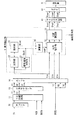
図1は、本発明の一実施の形態に係る映像表示装置の全体構成を表すものである。この映像表示装置は、チューナ11、Y/C分離回路12、クロマデコーダ13、スイッチ14、黒帯検出部2、画像処理部3、マトリクス回路41、ドライバ42および表示部5を備えている。なお、本発明の一実施の形態に係る映像信号処理装置および映像表示方法は、本実施の形態に係る映像表示装置によって具現化されるので、以下、併せて説明する。
FIG. 1 shows the overall configuration of a video display apparatus according to an embodiment of the present invention. This video display device includes a tuner 11, a Y /
この画像表示装置へ入力される画像信号は、TVからのテレビ信号のほか、VCR(Video Cassette Recorder)やDVD等の出力であってよい。このように複数種の媒体から画像情報を取り込み、各自について画面表示を行うことは、近年のテレビジョンやパーソナルコンピュータ(PC)においては一般的になってきている。 The image signal input to the image display device may be a TV signal from a TV, or an output such as a VCR (Video Cassette Recorder) or a DVD. It has become common in recent televisions and personal computers (PCs) to capture image information from a plurality of types of media and perform screen display for each of them.
チューナ11は、TVからのテレビ信号を受信すると共に復調し、コンポジット信号(CVBS;Composite Video Burst Signal)として出力するものである。 The tuner 11 receives and demodulates a television signal from the TV and outputs it as a composite signal (CVBS; Composite Video Burst Signal).
Y/C分離回路12は、チューナ11からのコンポジット信号、またはVCRやDVD1からのコンポジット信号をそれぞれ、輝度信号Y1と色信号C1とに分離して出力するものである。
The Y /
クロマデコーダ13は、Y/C分離回路12によって分離された輝度信号Y1および色信号C1を、輝度信号Y1および色差信号U1,V1からなるYUV信号(Y1,U1,V1)として出力するものである。
The
なお、このYUV信号は、2次元ディジタル画像の画像データであり、画像上の位置に対応する画素値の集合である。そのうち、輝度信号Yは輝度レベルを表現し、白100%である白レベルと、黒100%である黒レベルとの間の振幅値をとるようになっている。また、画像信号の白100%は、IRE(Institute of Radio Engineers)という画像信号の相対的な比を表す単位において、100(IRE)と定められている。日本のNTSC(National Television Standards Committee)信号の規格では、白レベルが100IRE,黒レベルが0IREである。一方、色差信号U,Vはそれぞれ、青(B;Blue)から輝度信号Yを引いた信号B−Y、赤(R;Red)から輝度信号Yを引いた信号R−Yに対応しており、これらU信号,V信号を輝度信号Yと組み合わせることによって、色(色相,彩度,輝度)が表現されるようになっている。 The YUV signal is image data of a two-dimensional digital image, and is a set of pixel values corresponding to positions on the image. Among them, the luminance signal Y represents a luminance level, and takes an amplitude value between a white level which is 100% white and a black level which is 100% black. Further, 100% of white of the image signal is defined as 100 (IRE) in a unit representing a relative ratio of image signals called IRE (Institute of Radio Engineers). In the Japanese NTSC (National Television Standards Committee) signal standard, the white level is 100 IRE and the black level is 0 IRE. On the other hand, the color difference signals U and V correspond to a signal BY obtained by subtracting the luminance signal Y from blue (B) and a signal RY obtained by subtracting the luminance signal Y from red (R). By combining these U signal and V signal with the luminance signal Y, colors (hue, saturation, luminance) are expressed.
スイッチ14は、複数種の媒体からのYUV信号(ここではYUV信号(Y1,U1,V1)、およびDVD2からのYUV信号(Y2,U2,V2))を切り換えることにより、選択した信号をYUV信号(Yin,Uin,Vin)として出力するものである。
The
黒帯検出部2は、入力映像信号であるYUV信号(Yin,Uin,Vin)に含まれる黒帯領域を検出するものであり、具体的には輝度信号Yinに基づいて黒帯領域を検出し、検出結果Koutを後述する画像処理部3へ出力するものである。この黒帯検出部2は、信号種別判別部21と、計測部22と、検出部23とを有している。
The black
図2は、この黒帯検出部2の詳細構成を表したものである。
FIG. 2 shows a detailed configuration of the black
信号種別判別部21は、入力映像信号の種別を判別するものであり、具体的には、例えばNTSCの480i信号や、PAL(Phase Alternating Line)の576i信号などの種別が判別されるようになっている。
The signal
計測部22は、信号レベル比較部221と、計測結果出力部222とを有しており、入力映像信号のうちの指令された計測領域について、単位フレーム期間内に所定の計測を行うものである。具体的には、この計測領域内で画素ごとに、輝度信号Yinに基づいて設定されたしきい値Vt未満の信号レベルか否かを計測するようになっている。
The
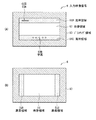
図3(A),(B)は、入力映像信号6に黒帯領域が含まれる場合の各領域を模式的に表したものである。図3(A)は、映像信号62の上下に黒帯領域61A,61Bが設けられたものであり、例えばシネマスコープサイズの映像信号などが該当する。また、黒帯領域61A内にはOSD(On Screen Display)63Aが挿入され、黒帯領域61B内には字幕63Bが挿入されている。また、これら映像領域62および黒帯領域61A,61Bの周囲には、ブランキング領域が設けられている。一方、図3(B)は、映像信号66の左右に黒帯領域65A,65Bが設けられたものであり、例えばサイドパネルの映像信号などが該当する。また、これら映像領域65および黒帯領域61A,61Bの周囲にも、ブランキング領域60が設けられている。なお、OSDや字幕は黒帯領域に挿入されている場合と挿入されていない場合があり、挿入されている場合においても、上下または左右の黒帯領域のどちらか一方または両方に挿入される場合がある。
FIGS. 3A and 3B schematically show each area when the
信号レベル比較部221は、例えば図4(A)に示したように入力映像信号6のうちの指令された計測領域64Aについて、単位フレーム期間内に、各画素の輝度信号Yinと設定されたしきい値Vtとの間の信号レベルの大小を比較し、しきい値Vt以上の信号レベルの画素位置を出力するものである。このしきい値Vtは、例えば映像領域62の画素位置が出力されてブランキング領域60および黒帯領域61A,61Bの画素位置が出力されないように設定される。
For example, as shown in FIG. 4A, the signal
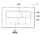
また、計測結果出力部222は、信号レベル比較部221から出力されるしきい値Vt以上の画素位置に基づいて、図4(A)に示したような、計測領域64A内での水平バックポーチ長Hbp、水平フロントポーチ長Hfp、垂直バックポーチ長Vbpおよび垂直フロントポーチ長Vfpをそれぞれ求めて出力するものである。なお、図4(A)中の計測領域64Aは、黒帯検出する際の基準となる基準領域の場合のものを表しているが、例えば図4(B)に示した計測領域64Bのように、計測領域の区間は任意に設定可能である。この計測領域の区間の増減については、後述する。
Further, the measurement
検出部23は、計測部22による水平バックポーチ長Hbp、水平フロントポーチ長Hfp、垂直バックポーチ長Vbpおよび垂直フロントポーチ長Vfpの計測結果、ならびに信号種別判別部21による信号種別判別結果Soutに基づいて、実際に入力映像信号6に含まれる黒帯領域を検出するものである。この検出部23は、黒帯判定部230と、基準領域設定部231と、増減幅初期値設定部232と、増減幅設定部233と、境界判定部234と、再検出回数設定部235と、下限値設定部236と、検出判定部237と、計測領域設定部238と、しきい値設定部239とを有している。
The
黒帯判定部230は、計測部22による水平バックポーチ長Hbp、水平フロントポーチ長Hfp、垂直バックポーチ長Vbpおよび垂直フロントポーチ長Vfpの計測結果Moutが、黒帯領域によるものであるか否かを判断するものである。
The black
基準領域設定部231は、黒帯検出する際の基準となる基準領域を設定するものであり、信号種別判別部21による信号種別判別結果Soutに応じて、例えば図5に示した入力映像信号6中の基準領域64Aのように設定される。また、増減幅初期値設定部232は、計測部22による計測区間を変化させる際の変化量(増減幅)の初期値を設定する部分である。この増減幅は、例えば図5に示したように計測領域64Aから計測領域64Bへと垂直方向に計測区間を変化させる場合、増減幅64Vのように表され、水平方向の場合も同様にして表される。また、増減幅初期値設定部232は、信号種別判別部21による信号種別判別結果Soutに応じて、増減幅の初期値を2のべき乗(2n(n:自然数))の値に設定するようになっている。具体的には、例えば入力映像信号6がNTSCの525i信号の場合には増減幅の初期値を64に設定し、入力映像信号6がプログレッシブ信号に変換された525p信号の場合には増減幅の初期値を128に設定するようになっている。
The reference
増減幅設定部233は、増減幅初期値設定部232によって設定された増減幅の初期値および黒帯判定部230による判定結果に基づいて、計測区間の増減幅を設定するものである。具体的には、この増減幅の絶対値は、増減幅初期値設定部232によって設定された初期値から始まり、1単位フレームの計測ごとに前回の増減幅の1/2を新たな増減幅として設定し直すようになっている。また、この増減幅の絶対値を現在の計測区間に対して加算するのかまたは減算するのかは、後述する黒帯判定部230による判定結果に応じて決定されるようになっている。
The increase / decrease
境界判定部234は、黒帯判定部230による判定結果および増減幅設定部233によって設定された計測区間の増減幅に基づいて、黒帯領域61A,61B,65A,65Bと映像領域62,66との境界を判定するものである。
Based on the determination result by the black
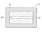
再検出回数設定部235は、後述する検出判定部237において黒帯領域を最終的に特定する際の再検出回数を設定するものである。この再検出回数は、0以上の整数で表される。また、下限値設定部236は、信号種別判別部21による信号種別判別結果Soutに応じて、境界判定部234によって判定された黒帯領域の境界から算出された映像領域62の水平幅または垂直幅の下限値を設定するものである。映像領域の垂直幅の場合、例えば図6に示した垂直幅62Vのように表され、これに下限値を設定することにより、暗いシーン等での誤検出(図6では、入力映像信号6中に黒帯領域が存在せず、映像信号62による暗いシーン等が表されている場合を示している)を防止するようになっている。
The redetection
検出判定部237は、境界判定部234による黒帯領域の境界判定結果、再検出回数設定部235により設定された再検出回数および下限値設定部236により設定された映像領域幅の下限値に基づいて、入力映像信号6に含まれる黒帯領域を最終判定し、確定した黒帯検出結果Koutを画像処理部3へ出力するものである。
The
計測領域設定部238は、増減幅設定部233によって設定された計測区間の増減幅に基づいて計測部22での計測領域を設定し、逐次信号レベル比較部221へ出力するものである。また、しきい値設定部239は、計測部22での計測の際に用いられる信号レベルのしきい値Vtを設定し、そのしきい値Vtを信号レベル比較部221へ出力するものである。なお、前述のように計測領域内においてしきい値Vt未満の信号レベルの領域が、黒帯領域となりうる。
The measurement
図1の説明に戻り、画像処理部3は、黒帯検出部2による黒帯検出結果Kout、およびこの黒帯検出部2内の信号種別判別部21による入力映像信号の種別判別結果Soutに基づいて、入力映像信号であるYUV信号(Yin,Uin,Vin)に対して画像処理を行うものである。具体的には、入力映像信号のアスペクト比を保ちつつ、その入力映像信号を拡大または縮小する処理(アスペクト比調整処理)を行うようになっており、表示部5の表示サイズ(画素数)、黒帯検出結果Koutおよび種別判別結果Soutに基づいて入力映像信号の拡大または縮小の比率を演算する演算部31と、この演算部31による演算結果Cout(拡大縮小比率)に基づいて入力映像信号であるYUV信号(Yin,Uin,Vin)の拡大または縮小を行う拡大縮小部32と、この拡大縮小部32によって黒帯領域内の字幕が欠落しないように拡大または縮小された映像信号に対して位置調整を行う位置調整部33とを有している。
Returning to the description of FIG. 1, the
マトリクス回路41は、画像処理部3によって画像処理(アスペクト比調整処理)後のYUV信号(Yout,Uout,Vout)をRGB信号に再生すると共に、この再生されたRGB信号(Rout,Gout,Bout)をドライバ42へ出力するものである。
The
ドライバ42は、マトリクス回路41から出力されるRGB信号(Rout,Gout,Bout)に基づいてディスプレイ5に対する駆動信号を生成し、この駆動信号をディスプレイ5へ出力するものである。
The
表示部5は、ドライバ42から出力される駆動信号に応じて、画像処理部3によって画像処理(アスペクト比調整処理)後のYUV信号(Yout,Uout,Vout)に基づく映像表示を行うものである。この表示部5はどのような種類の表示デバイスであってもよく、例えばCRT(Cathode-Ray Tube)や、LCD(Liquid Crystal Display)、PDP(Plasma Display Panel)、有機または無機のEL(ElectroLuminescence)ディスプレイ等が用いられる。
The
次に、本実施の形態の映像表示装置の動作について説明する。最初に、この映像表示装置の基本動作について説明する。 Next, the operation of the video display apparatus according to this embodiment will be described. First, the basic operation of this video display apparatus will be described.
まず、この映像表示装置へ入力される映像信号が、YUV信号に復調される。具体的には、TVからのテレビ信号は、チューナ11で復調されてコンポジット信号となり、VCRやDVD1からは、コンポジット信号が直接、映像表示装置へ入力される。そしてこれらコンポジット信号は、Y/C分離回路12において、輝度信号Y1と色信号C1とに分離され、クロマデコーダ13において、YUV信号(Y1,U1,V1)にデコードされる。一方、DVD2からは、YUV信号(Y2,U2,V2)が直接、映像表示装置へ入力される。
First, a video signal input to the video display device is demodulated into a YUV signal. Specifically, the TV signal from the TV is demodulated by the tuner 11 to become a composite signal, and the composite signal is directly input from the VCR or
次いで、スイッチ14において、これらYUV信号(Y1,U1,V1)とYUV信号(Y2,U2,V2)とのうち、一方のYUV信号が選択され、YUV信号(Yin,Uin,Vin)として出力される。そして、このYUV信号(Yin,Uin,Vin)のうち、輝度信号Yinは、黒帯検出部2内の信号種別判別部21および計測部22、ならびに画像処理部3内の拡大縮小部32へそれぞれ出力され、色差信号Uin,Vinは、それぞれこの画像処理部3内の拡大縮小部32へ出力される。
Next, in the
ここで、黒帯検出部2では、入力映像信号であるYUV信号(Yin,Uin,Vin)に含まれる黒帯領域が検出される。具体的には、輝度信号Yinに基づいて黒帯領域が検出され、検出結果Koutが画像処理部3へ出力される。より具体的には、計測部22において、入力映像信号のうちの指令された計測領域について、単位フレーム期間内に画素ごとに、輝度信号Yinがしきい値Vt未満の信号レベルか否かが計測され、検出部23において、計測部22による水平バックポーチ長Hbp、水平フロントポーチ長Hfp、垂直バックポーチ長Vbpおよび垂直フロントポーチ長Vfpの計測結果、ならびに信号種別判別部21による信号種別判別結果Soutに基づいて、入力映像信号6に含まれる黒帯領域が検出され、その黒帯検出結果Koutが画像処理部へ出力される。
Here, the black
また、画像処理部3では、黒帯検出部2による黒帯検出結果Kout、および信号種別判別部21による入力映像信号の種別判別結果Soutに基づいて、入力映像信号であるYUV信号(Yin,Uin,Vin)に対して画像処理、具体的には入力映像信号のアスペクト比を保ちつつその入力映像信号を拡大または縮小する処理(アスペクト比調整処理)がなされる。
Further, in the
次いで、マトリクス回路41では、画像処理部3によって画像処理(アスペクト比調整処理)後のYUV信号(Yout,Uout,Vout)がRGB信号(Rout,Gout,Bout)に再生され、ドライバ42では、このRGB信号(Rout,Gout,Bout)に基づいて駆動信号が生成され、この駆動信号に基づいて、表示部5に映像が表示される。
Next, in the
次に、図7〜図10を参照して、本発明の特徴的部分の1つである、計測部22による計測処理の詳細について説明する。
Next, with reference to FIG. 7 to FIG. 10, details of measurement processing by the
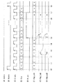
図7〜図10はそれぞれ、計測部22による水平バックポーチ長Hbp、水平フロントポーチ長Hfp、垂直バックポーチ長Vbpおよび垂直フロントポーチ長Vfpの計測方法の一例を、タイミング図で表したものである。これらの図において、Hsyncは水平同期信号を、Vsyncは垂直同期信号を、Clockは画素ごとの周期に対応したクロック(ドットクロック)信号を、H_actは水平方向におけるしきい値Vt以上の信号レベルの画素位置に対応する水平アクティブ信号を、V_actは各1水平期間において1画素でも水平アクティブ信号H_actが「H」レベルとなった場合にアクティブとなる垂直アクティブ信号を、Hbp_cntは水平バックポーチ用カウンタ出力を、Hfp_cntは水平フロントポーチ用カウンタ出力を、Vbp_cntは垂直バックポーチ用カウンタ出力を、Vfp_cntは垂直フロントポーチ用カウンタ出力を、Hbp_latは1水平期間前の水平バックポーチ用カウンタ出力Hbp_cntの確定値をラッチ(保持)したものに対応する水平バックポーチ用ラッチ出力を、Hfp_latは1水平期間前の水平フロントポーチ用カウンタ出力Hfp_cntの確定値をラッチしたものに対応する水平フロントポーチ用ラッチ出力を、Hbp_outは最終的に水平バックポーチ長Hbpの確定値として出力される水平バックポーチ長出力を、Hfp_outは最終的に水平フロントポーチ長Hfpの確定値として出力される水平フロントポーチ長出力を、Vbp_outは1垂直期間前の垂直バックポーチ用カウンタ出力Vbp_cntの確定値をラッチしたものに対応すると共に最終的に垂直バックポーチ長Vbpの確定値として出力される垂直バックポーチ長出力を、Vfp_outは1垂直期間前の垂直フロントポーチ用カウンタ出力Vfp_cntの確定値をラッチしたものに対応すると共に最終的に垂直フロントポーチ長Vfpの確定値として出力される垂直フロントポーチ長出力を、それぞれ表している。また、輝度信号Yin中に示した「<」はしきい値Vt未満の信号レベルであることを表し、「>」はしきい値以上の信号レベルであることを表している。
FIGS. 7 to 10 are timing charts showing examples of measuring methods of the horizontal back porch length Hbp, the horizontal front porch length Hfp, the vertical back porch length Vbp, and the vertical front porch length Vfp by the measuring
まず、図7に示した水平バックポーチ長Hbpの測定については、以下のようにして行われる。 First, the measurement of the horizontal back porch length Hbp shown in FIG. 7 is performed as follows.
タイミングt0において水平同期信号Hsync(図7(B))が「H」レベルになると、その立ち上がりエッジにおいて、水平バックポーチ用カウンタ出力Hbp_cnt(図7(F))がリセットとなり、「0」が出力される。そしてこのタイミングt0以降は、クロック信号Clock(図7(C))の立ち上がりエッジ(タイミングt1,t2,…)において、水平バックポーチ用カウンタ出力Hbp_cntの値が1ずつ増加していく。 When the horizontal synchronization signal Hsync (FIG. 7B) becomes “H” level at timing t0, the horizontal back porch counter output Hbp_cnt (FIG. 7F) is reset at the rising edge, and “0” is output. Is done. After this timing t0, the value of the horizontal back porch counter output Hbp_cnt increases by 1 at the rising edge (timing t1, t2,...) Of the clock signal Clock (FIG. 7C).
次に、タイミングt4において輝度信号Yin(図7(D))がしきい値Vt以上の信号レベルとなると、クロック信号Clockの次の立ち上がりエッジであるタイミングt5において、水平アクティブ信号H_act(図7(E))が「H」レベルとなる。すると、この水平アクティブ信号H_actが「H」レベルの間(タイミングt5〜t7)、水平バックポーチ用カウンタ出力Hbp_cntの値が固定となる(図7では、「4」に固定されている)。このときの水平バックポーチ用カウンタ出力Hbp_cntの値がその水平期間における確定値となり、水平バックポーチ用ラッチ出力Hbp_lat(図7(G))として更新され、保持される。また、このとき、1水平期間前(更新前)の水平バックポーチ用ラッチ出力Hbp_latの値(図7では、「6」となっている)と、これまでの測定における水平バックポーチ長Hbpの最小値に対応する水平バックポーチ長出力Hbp_out(図7(H))の値(図7では、「10」となっている)との大小が比較され、小さいほうの値が新たな水平バックポーチ長出力Hbp_outとして更新される(図7では、「10」から「6」に更新されている)。 Next, when the luminance signal Yin (FIG. 7D) becomes a signal level equal to or higher than the threshold value Vt at the timing t4, the horizontal active signal H_act (FIG. E)) becomes “H” level. Then, while the horizontal active signal H_act is at the “H” level (timing t5 to t7), the value of the horizontal back porch counter output Hbp_cnt is fixed (in FIG. 7, it is fixed to “4”). At this time, the value of the horizontal back porch counter output Hbp_cnt becomes a fixed value in the horizontal period, and is updated and held as the horizontal back porch latch output Hbp_lat (FIG. 7G). At this time, the horizontal back porch latch output Hbp_lat value (in FIG. 7, “6”) one horizontal period before (updating) and the minimum horizontal back porch length Hbp in the previous measurements. The horizontal back porch length output Hbp_out (FIG. 7H) corresponding to the value is compared with the value (in FIG. 7, “10”), and the smaller value is the new horizontal back porch length. It is updated as the output Hbp_out (in FIG. 7, it is updated from “10” to “6”).
次に、タイミングt6において輝度信号Yinが再びしきい値Vt未満の信号レベルとなると、クロック信号Clockの次の立ち上がりエッジであるタイミングt7において、水平アクティブ信号H_actが「L」レベルへと戻り、水平バックポーチ用カウンタ出力Hbp_cntの値が再び1ずつ増加していく。そしてタイミングt8において水平同期信号Hsyncが「H」レベルとなることで、1水平期間の計測が終了となる。 Next, when the luminance signal Yin again becomes a signal level lower than the threshold value Vt at the timing t6, the horizontal active signal H_act returns to the “L” level at the timing t7 which is the next rising edge of the clock signal Clock, and the horizontal The value of the back porch counter output Hbp_cnt again increases by one. Then, at the timing t8, the horizontal synchronization signal Hsync becomes “H” level, whereby the measurement for one horizontal period is completed.
このような1水平期間の計測が単位フレーム期間にわたって行われることで、この単位フレーム期間内の短時間において、計測領域64A,64Bの左端から連続して存在するしきい値Vt未満の画素数の最小値に対応する水平バックポーチ長Hbpが、計測部22から出力される。
By performing such measurement in one horizontal period over the unit frame period, the number of pixels less than the threshold value Vt existing continuously from the left end of the
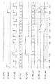
また、図8に示した水平フロントポーチ長Hfpの測定については、基本的には水平バックポーチ長Hbpの測定と同様に、以下のようにして行われる。 Further, the measurement of the horizontal front porch length Hfp shown in FIG. 8 is basically performed as follows, similarly to the measurement of the horizontal back porch length Hbp.
まず、タイミングt10において水平同期信号Hsync(図8(B))が「H」レベルになり、タイミングt11において輝度信号Yin(図8(D))がしきい値Vt以上の信号レベルとなると、クロック信号Clock(図8(C))の次の立ち上がりエッジであるタイミングt12において、水平アクティブ信号H_act(図8(E))が「H」レベルとなる。すると、この水平アクティブ信号H_actが「H」レベルの間(タイミングt12〜t14)、水平フロントポーチ用カウンタ出力Hfp_cnt(図8(F))がリセットとなり、「0」が出力される。 First, when the horizontal synchronization signal Hsync (FIG. 8B) becomes “H” level at timing t10 and the luminance signal Yin (FIG. 8D) becomes a signal level equal to or higher than the threshold value Vt at timing t11, At timing t12, which is the next rising edge of the signal Clock (FIG. 8C), the horizontal active signal H_act (FIG. 8E) becomes the “H” level. Then, while the horizontal active signal H_act is at the “H” level (timing t12 to t14), the horizontal front porch counter output Hfp_cnt (FIG. 8F) is reset and “0” is output.
次に、タイミングt13において輝度信号Yinが再びしきい値Vt未満の信号レベルとなると、クロック信号Clockの次の立ち上がりエッジであるタイミングt14において、水平アクティブ信号H_actが「L」レベルへ戻る。すると、このタイミングt14以降(タイミングt14,t15,…)、水平フロントポーチ用カウンタ出力Hfp_cntの値が1ずつ増加していくようになる。 Next, when the luminance signal Yin again becomes a signal level lower than the threshold value Vt at the timing t13, the horizontal active signal H_act returns to the “L” level at the timing t14 which is the next rising edge of the clock signal Clock. Then, after the timing t14 (timing t14, t15,...), The value of the horizontal front porch counter output Hfp_cnt increases by one.
次に、タイミングt18において水平同期信号Hsyncが再び「H」レベルになると、このときの水平フロントポーチ用カウンタ出力Hfp_cntの値がその水平期間における確定値となり、水平フロントポーチ用ラッチ出力Hfp_lat(図8(G))として更新され、保持される。またこのとき、1水平期間前(更新前)の水平フロントポーチ用ラッチ出力Hbp_latの値(図8では、「6」となっている)と、これまでの測定における水平フロントポーチ長Hfpの最小値に対応する水平フロントポーチ長出力Hfp_out(図8(H))の値(図8では、「10」となっている)との大小が比較され、小さいほうの値が新たな水平フロントポーチ長出力Hfp_outとして更新される(図8では、「10」から「6」に更新されている)。以上で、1水平期間の計測が終了となる。 Next, when the horizontal synchronization signal Hsync becomes “H” level again at the timing t18, the value of the horizontal front porch counter output Hfp_cnt at this time becomes a determined value in the horizontal period, and the horizontal front porch latch output Hfp_lat (FIG. 8). (G)) is updated and held. At this time, the value of the horizontal front porch latch output Hbp_lat before the horizontal period (before update) (“6” in FIG. 8) and the minimum value of the horizontal front porch length Hfp in the measurement so far Is compared with the value of the horizontal front porch length output Hfp_out (FIG. 8 (H)) (which is “10” in FIG. 8), and the smaller value is the new horizontal front porch length output. It is updated as Hfp_out (in FIG. 8, it is updated from “10” to “6”). This completes the measurement for one horizontal period.
このような1水平期間の計測が単位フレーム期間にわたって行われることで、この単位フレーム期間内の短時間において、計測領域64A,64Bの右端から連続して存在するしきい値Vt未満の画素数の最小値に対応する水平フロントポーチ長Hfpが、計測部22から出力される。
By performing such measurement for one horizontal period over the unit frame period, the number of pixels less than the threshold value Vt existing continuously from the right end of the
また、図9に示した垂直バックポーチ長Vbpの測定については、以下のようにして行われる。 Further, the measurement of the vertical back porch length Vbp shown in FIG. 9 is performed as follows.
タイミングt20において垂直同期信号Vsync(図9(A))が「H」レベルになると、その立ち上がりエッジにおいて、垂直バックポーチ用カウンタ出力Vbp_cnt(図9(E))がリセットとなり、「0」が出力される。そしてこのタイミングt20以降は、水平同期信号Hsync(図9(B))の立ち上がりエッジ(タイミングt21,t22,…)において、垂直バックポーチ用カウンタ出力Vbp_cntの値が1ずつ増加していく。 When the vertical synchronization signal Vsync (FIG. 9A) becomes “H” level at timing t20, the vertical back porch counter output Vbp_cnt (FIG. 9E) is reset and “0” is output at the rising edge. Is done. After this timing t20, the value of the vertical back porch counter output Vbp_cnt increases by 1 at the rising edge (timing t21, t22,...) Of the horizontal synchronization signal Hsync (FIG. 9B).
次に、タイミングt22〜t25の1水平期間内のタイミングt23〜t24において、輝度信号Yinがしきい値Vt以上の信号レベルとなって水平アクティブ信号H_act(図9(C))が「H」レベルとなると、水平同期信号Hsyncの次の立ち上がりエッジであるタイミングt25において、垂直アクティブ信号V_act(図9(D))が「H」レベルになる。すると、この垂直アクティブ信号V_actが「H」レベルの間(タイミングt25〜t28)、すなわち水平アクティブ信号H_actが1水平期間中に「H」レベルとなる期間があるうちは、垂直バックポーチ用カウンタ出力Vbp_cntの値が固定となる(図9では、「2」に固定されている)。また、このときの垂直バックポーチ用カウンタ出力Vbp_cntの値がその垂直期間における確定値となり、垂直バックポーチ長出力Vbp_out(図9(F))として更新され、保持される。 Next, at timings t23 to t24 within one horizontal period from timings t22 to t25, the luminance signal Yin becomes a signal level equal to or higher than the threshold value Vt, and the horizontal active signal H_act (FIG. 9C) is at the “H” level. Then, at the timing t25, which is the next rising edge of the horizontal synchronization signal Hsync, the vertical active signal V_act (FIG. 9D) becomes the “H” level. Then, while the vertical active signal V_act is at the “H” level (timing t25 to t28), that is, while there is a period during which the horizontal active signal H_act is at the “H” level in one horizontal period, the counter output for the vertical back porch is output. The value of Vbp_cnt is fixed (in FIG. 9, it is fixed to “2”). Further, the value of the vertical back porch counter output Vbp_cnt at this time becomes a definite value in the vertical period, and is updated and held as the vertical back porch length output Vbp_out (FIG. 9F).
次に、タイミングt27〜t28の1水平期間内で水平アクティブ信号H_actが「L」レベルに固定されていると、水平同期信号Hsyncの次の立ち上がりエッジであるタイミングt28において、垂直アクティブ信号V_actが「L」レベルへと戻り、垂直バックポーチ用カウンタ出力Vbp_cntの値が再び1ずつ増加していく。そしてタイミングt29において垂直同期信号Vsyncが「H」レベルとなることで、1垂直期間の計測が終了となる。 Next, when the horizontal active signal H_act is fixed to the “L” level within one horizontal period from timing t27 to t28, the vertical active signal V_act is “at” at timing t28 which is the next rising edge of the horizontal synchronization signal Hsync. Returning to the “L” level, the value of the vertical back porch counter output Vbp_cnt increases by one again. Then, at the timing t29, the vertical synchronization signal Vsync becomes “H” level, and thus the measurement for one vertical period is completed.
このような1垂直期間の計測が単位フレーム期間(単位フレーム期間が1垂直期間の場合には、1垂直期間のみの測定)にわたって行われることで、この単位フレーム期間内の短時間において、計測領域64A,64Bの上端から連続して存在するしきい値Vt未満の画素数の最小値に対応する垂直バックポーチ長Vbpが、計測部22から出力される。
Such measurement of one vertical period is performed over a unit frame period (in the case where the unit frame period is one vertical period, measurement of only one vertical period), so that the measurement region can be measured in a short time within the unit frame period. The vertical back porch length Vbp corresponding to the minimum value of the number of pixels less than the threshold value Vt continuously present from the upper ends of 64A and 64B is output from the measuring
また、図10に示した垂直フロントポーチ長Vfpの測定については、基本的には垂直バックポーチ長Vbpの測定と同様に、以下のようにして行われる。 Further, the measurement of the vertical front porch length Vfp shown in FIG. 10 is basically performed as follows, similarly to the measurement of the vertical back porch length Vbp.
まず、タイミングt30において垂直同期信号Vsync(図10(A))が「H」レベルになり、タイミングt31〜t32において輝度信号Yinがしきい値Vt以上の信号レベルとなって水平アクティブ信号H_act(図10(C))が「H」レベルになると、水平同期信号Hsync(図10(B))の次の立ち上がりエッジであるタイミングt33において、垂直アクティブ信号V_act(図10(D))が「H」レベルとなる。すると、この垂直アクティブ信号V_actが「H」レベルの間(タイミングt33〜t35)、垂直フロントポーチ用カウンタ出力Vfp_cnt(図10(E))がリセットとなり、「0」が出力される。 First, at timing t30, the vertical synchronization signal Vsync (FIG. 10A) becomes the “H” level, and at timings t31 to t32, the luminance signal Yin becomes a signal level equal to or higher than the threshold value Vt and the horizontal active signal H_act (FIG. 10 (C)) becomes “H” level, the vertical active signal V_act (FIG. 10D) is “H” at timing t33 which is the next rising edge of the horizontal synchronization signal Hsync (FIG. 10B). Become a level. Then, while the vertical active signal V_act is at the “H” level (timing t33 to t35), the vertical front porch counter output Vfp_cnt (FIG. 10E) is reset and “0” is output.
次に、タイミングt34〜t35の1水平期間内で水平アクティブ信号H_actが「L」レベルに固定されていると、水平同期信号Hsyncの次の立ち上がりエッジであるタイミングt35において、垂直アクティブ信号H_actが「L」レベルへ戻る。すると、このタイミングt35以降(タイミングt35,t36,…)、垂直フロントポーチ用カウンタ出力Vfp_cntの値が1ずつ増加していくようになる。 Next, when the horizontal active signal H_act is fixed to the “L” level within one horizontal period from timing t34 to t35, the vertical active signal H_act is “at” at the timing t35 that is the next rising edge of the horizontal synchronization signal Hsync. Return to the “L” level. Then, after this timing t35 (timing t35, t36,...), The value of the vertical front porch counter output Vfp_cnt increases by one.
次に、タイミングt38において垂直同期信号Vsyncが再び「H」レベルになると、このときの垂直フロントポーチ用カウンタ出力Vfp_cntの値がその垂直期間における確定値となり、垂直フロントポーチ長出力Vfp_out(図10(F))として更新され、保持される。以上で、1垂直期間の計測が終了となる。 Next, when the vertical synchronization signal Vsync becomes “H” level again at the timing t38, the value of the vertical front porch counter output Vfp_cnt at this time becomes a determined value in the vertical period, and the vertical front porch length output Vfp_out (FIG. 10 ( F)) is updated and held. This completes the measurement for one vertical period.
このような1垂直期間の計測が単位フレーム期間にわたって行われることで、この単位フレーム期間内の短時間において、計測領域64A,64Bの下端から連続して存在するしきい値Vt未満の画素数の最小値に対応する垂直フロントポーチ長Vfpが、計測部22から出力される。
By performing such measurement in one vertical period over the unit frame period, the number of pixels less than the threshold value Vt continuously present from the lower ends of the
なお、このような計測部22による水平バックポーチ長Hbp、水平フロントポーチ長Hfp、垂直バックポーチ長Vbpおよび垂直フロントポーチ長Vfpの計測は、順次行うようにしてもよく、2以上の計測を並列して行うようにしてもよい。並列して行うようにした場合、水平バックポーチ長Hbp、水平フロントポーチ長Hfp、垂直バックポーチ長Vbpおよび垂直フロントポーチ長Vfpの計測を単位フレーム期間内に全て計測することができ、より高速な計測が可能となる。
Note that the measurement of the horizontal back porch length Hbp, horizontal front porch length Hfp, vertical back porch length Vbp, and vertical front porch length Vfp by the
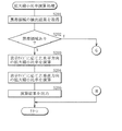
次に、図11〜図23を参照して、本発明の特徴的部分の1つである、黒帯検出部2における黒帯検出処理について詳細に説明する。図11は、この黒帯検出部2における黒帯検出処理を流れ図で表したものである。
Next, with reference to FIG. 11 to FIG. 23, the black band detection process in the black
この黒帯検出処理では、例えば図12(A)に示したように映像領域62の上下に黒帯領域61A,61Bがあると共にこれら黒帯領域61A,61B内にOSD63Aや字幕63Bが含まれているような場合には、入力映像信号6の水平バックポーチ長H1Aおよび水平フロントポーチ長H1B、入力映像信号6の垂直バックポーチを含めたOSD63Aの最上端までの長さV0Aおよび黒帯領域61Aの垂直幅V1A、入力映像信号6の垂直フロントポーチを含めた字幕63Bの最下端までの長さV0Bおよび黒帯領域61Bの垂直幅V1B、ならびに映像領域62の垂直幅V2などが検出される。
In this black band detection process, for example, as shown in FIG. 12A,
また、例えば図12(B)に示したように映像領域66の左右に黒帯領域65A,65Bがあるような場合には、入力映像信号6の垂直バックポーチ長V1Aおよび垂直フロントポーチ長V1B、入力映像信号6の水平バックポーチを含めた黒帯領域65Aの水平幅H1A、入力映像信号6の水平フロントポーチを含めた黒帯領域65Bの水平幅H1B、ならびに映像領域62の水平幅H2などが検出される。
For example, as shown in FIG. 12B, when there are
また、この黒帯検出処理では、例えば図13(A),(B)および図14(A),(B)中の計測領域64A(基準領域)、計測領域64B1〜64B3および矢印P21,P22,P31,P32,P41,P42,P51,P52にそれぞれ示したように、計測領域の増減幅64V,64Hが前回の増減幅の1/2に再設定されつつ、黒帯検出が行われるようになっている。つまり、この黒帯検出処理では、2分探索を用いた黒帯検出がなされ、これにより詳細は後述するが、高速に(増減幅の初期値が2nに設定された場合、遅くとも(n+1)個分の単位フレーム期間内に黒帯検出処理が完了し、図12(A),(B)に示したような各種パラメータが出力される。)検出することができるようになっている。
In this black belt detection process, for example, the
この黒帯検出処理では、最初に黒帯検出処理が行われる(ステップS11)。 In this black band detection process, a black band detection process is first performed (step S11).
具体的には、図15の流れ図に示したように、まず、しきい値設定部239が、信号レベルのしきい値Vtを設定し、信号レベル比較部221へ出力する(図15のステップS111)。次に、信号種別判別結果Soutに基づいて、基準領域設定部231が基準領域を設定する(ステップS112)。次に、計測領域設定部238が、設定された基準領域を計測領域64Aに設定し、信号レベル比較部221へ出力する(ステップS113)。
Specifically, as shown in the flowchart of FIG. 15, first, the threshold
そして次の単位フレームへ移行するまで待機すると(ステップS114)、黒帯判定部230は計測部22から計測結果Mout(計測領域64A内の水平バックポーチ長Hbp、水平フロントポーチ長Hfp、垂直バックポーチ長Vbpおよび垂直フロントポーチ長Vfpの計測結果)を取得する(ステップS115)。ここで、黒帯判定部230が、この計測結果Moutに基づいて計測領域64A内に黒帯領域が存在するか否かを判断し(ステップS116)、存在すると判断された場合には(ステップS116:Y)、次の境界判定処理1(図11のステップS12)へと移行する。
Then, when waiting for the transition to the next unit frame (step S114), the black
一方、ステップS116において黒帯領域がないと判断された場合(ステップS116:N)、次に黒帯検出処理を終了するか否かが判断される(ステップS117)。終了すると判断された場合には(ステップS117:Y)、黒帯検出処理が終了となる(図11の「エンド」)。一方、終了せずに続行すると判断された場合には(ステップS117:N)、検出判定部237が、黒帯領域の検出回数を示す検出回数カウンタの値をリセットして0を設定する(ステップS118)と共に、基準領域64Aを検出結果Koutとして画像処理部3へ出力する(ステップS119)。そして黒帯領域が存在すると判断されるか黒帯検出処理を終了すると判断されるまで、ステップS111〜S119の処理が繰り返される。
On the other hand, when it is determined in step S116 that there is no black band region (step S116: N), it is next determined whether or not to end the black band detection process (step S117). If it is determined to end (step S117: Y), the black band detection process ends (“END” in FIG. 11). On the other hand, if it is determined to continue without ending (step S117: N), the
次いで、境界判定処理1が行われる(図11のステップS12)。具体的には、図16および図17の流れ図で示したような処理がなされる。
Next,
この境界判定処理1では、前述したような2分探索の手法を用いて、入力映像信号6内の上側の黒帯領域61Aまたは左側の黒帯領域65Aと映像領域62または映像領域66との境界位置が判定される。
In this
具体的には、まず計測領域設定部238が最初の計測領域を設定し、信号レベル比較部221へ出力する(図16のステップS121)。より具体的には、上側の黒帯領域61Aの境界位置を判定する場合には、水平方向の開始位置および終了位置、ならびに垂直方向の開始位置が、それぞれ基準領域64Aにおける水平方向の開始位置および終了位置、ならびに垂直方向の開始位置に設定される一方、垂直方向の終了位置は、基準領域64Aの垂直開始位置に増減幅初期値設定部232により設定された垂直方向の増減幅初期値が加算された位置が設定される。また、左側の黒帯領域65Aの境界位置を判定する場合には、垂直方向の開始位置および終了位置、ならびに水平方向の開始位置が、それぞれ基準領域64Aにおける垂直方向の開始位置および終了位置、ならびに水平方向の開始位置に設定される一方、水平方向の終了位置は、基準領域64Aの水平開始位置に増減幅初期値設定部232により設定された水平方向の増減幅初期値が加算された位置が設定される。なお、これら水平方向および垂直方向の増減初期値は、信号種別判別結果Soutに基づいて設定され、この境界判定処理1では上側または左側の境界位置を判定することから、基準領域64Aの水平方向および垂直方向の幅の1/2以下に設定されることが望ましい。より短時間に黒帯領域の境界位置を判定できるからである。
Specifically, first, the measurement
次に、次の単位フレームへ移行するまで待機し(ステップS122)、黒帯判定部230が計測部22から計測結果Moutを取得する(ステップS123)。そして増減幅設定部233は、計測領域の増減幅を半減させる。すなわち、前回の計測領域の増減幅の1/2を、新たな増減幅として設定し直す。次に増減幅設定部233は、このようにして設定した新たな増減幅が1未満か否かを判断し(ステップS125)、1未満である場合には(ステップS125:Y)、これ以上2分探索の手法を用いる必要がないと判断し、次の処理(図17のステップS129)へと移行する。
Next, it waits until it transfers to the next unit frame (step S122), and the black
一方、ステップS125において新たな増減幅が1未満ではないと判断された場合(ステップS125:N)、次に黒帯判定部230が、計測結果Moutに基づいて計測領域64B内に黒帯領域のみ(ブランキング領域60を含む黒帯領域)が存在するのか否かを判断する(ステップS126)。そして計測領域設定部238は、この判断結果に応じて、ステップS124において増減幅設定部233により設定された新たな計測区間の増減幅を、前回の計測領域に対して加算または減算することにより、新たな計測領域を再設定する(ステップS127,S128)。
On the other hand, when it is determined in step S125 that the new increase / decrease width is not less than 1 (step S125: N), the black
具体的には、例えば図18(A)に示したように計測領域64B1内に黒帯領域以外の映像領域62も存在する場合には(ステップS126:N)、図中の矢印P61のように、前回の計測領域64B1の終了位置から新たな増減幅分だけ減算することにより、新たな計測領域64B2を再設定する(ステップS127)。一方、例えば例えば図18(B)に示したように計測領域64B3内に黒帯領域のみが存在する場合には(ステップS126:Y)、図中の矢印P62のように、前回の計測領域64B3の終了位置から新たな増減幅分だけ加算することにより、新たな計測領域64B4を再設定する(ステップS128)。そしてステップS127,128以降は、ステップS125において新たな増減幅が1未満である、すなわち黒帯領域と映像領域との境界位置が検出されていると判断される(ステップS125:Y)まで、ステップS122〜ステップS127,S128の処理が繰り返される。なお、図18では上側の黒帯領域61Aの境界位置判定の場合を示したが、左側の黒帯領域65Aの境界位置判定の場合も同様の処理がなされる。
Specifically, for example, as shown in FIG. 18A, when the
次に、ステップS126と同様にして、黒帯判定部230が、計測結果Moutに基づいて計測領域64B内に黒帯領域のみが存在するのか否かを判断する(図16のステップS129)。黒帯領域のみではないと判断された場合には(ステップS129:Y)、ステップS127と同様にして、前回の計測領域の終了位置から新たな増減幅分だけ減算することにより、新たな計測領域を再設定する(ステップS130)。一方、黒帯領域のみであると判断された場合には(ステップS129:N)、ステップS128と同様にして、前回の計測領域の終了位置から新たな増減幅分だけ加算することにより、新たな計測領域を再設定する(ステップS131)。
Next, similarly to step S126, the black
次に、次の単位フレームへ移行するまで待機し(ステップS132)、黒帯判定部230が計測部22から計測結果Moutを取得する(ステップS133)。そして境界判定部234は、このときの黒帯領域の上側または左側の境界位置を算出し(ステップS134)、検出判定部237へ出力することにより、境界判定処理1が終了し、次の処理へと移行する。
Next, it waits until it transfers to the next unit frame (step S132), and the black
次いで、境界判定処理2が行われる(図11のステップS14)。具体的には、図19および図20の流れ図で示したような処理がなされる。
Next,
この境界判定処理2では、上記した境界判定処理1と基本的に同様にして、入力映像信号6内の下側の黒帯領域61Bまたは右側の黒帯領域65Bと映像領域62または映像領域66との境界位置が判定される。
In the
具体的には、まず計測領域設定部238が最初の計測領域を設定し、信号レベル比較部221へ出力する(図19のステップS141)。より具体的には、下側の黒帯領域61Bの境界位置を判定する場合には、水平方向の開始位置および終了位置、ならびに垂直方向の終了位置が、それぞれ基準領域64Aにおける水平方向の開始位置および終了位置、ならびに垂直方向の終了位置に設定される一方、垂直方向の開始位置は、基準領域64Aの垂直終了位置から増減幅初期値設定部232により設定された垂直方向の増減幅初期値が減算された位置が設定される。また、右側の黒帯領域65Bの境界位置を判定する場合には、垂直方向の開始位置および終了位置、ならびに水平方向の終了位置が、それぞれ基準領域64Aにおける垂直方向の開始位置および終了位置、ならびに水平方向の終了位置に設定される一方、水平方向の開始位置は、基準領域64Aの水平終了位置から増減幅初期値設定部232により設定された水平方向の増減幅初期値が減算された位置が設定される。
Specifically, first, the measurement
次いで、それ以降のステップS142〜S153では、境界判定処理1のステップS122〜S133と基本的に同様の処理がなされる。ただし、ステップS147,S150では、例えば図21(A)中の矢印P71のように、前回の計測領域64B1の開始位置から新たな増減幅分または1だけ減算されることにより、新たな計測領域64B2が再設定される(ステップS147,S150)。また、ステップS148,S151では、例えば図21(B)中の矢印P72のように、前回の計測領域64B3の開始位置から新たな増減幅分または1だけ加算されることにより、新たな計測領域64B4を再設定される(ステップS148,S151)。
Subsequently, in subsequent steps S142 to S153, basically the same processing as steps S122 to S133 of the
そして境界判定部234は、図20のステップS154において黒帯領域の下側または右側の境界位置を算出して検出判定部237へ出力することにより、境界判定処理2が終了し、次の処理へと移行する。なお、図21では右側の黒帯領域65Bの境界位置判定の場合を示したが、下側の黒帯領域61Bの境界位置判定の場合も同様の処理がなされる。
Then, the
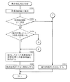
次いで、黒帯検出判定処理が行われる(図11のステップS16)。具体的には、図22および図23の流れ図で示したような処理がなされる。 Next, a black band detection determination process is performed (step S16 in FIG. 11). Specifically, the processing as shown in the flowcharts of FIGS. 22 and 23 is performed.
まず、検出判定部237は、境界判定部234によって境界判定処理1,2により求められた黒帯領域61A,61Bまたは黒帯領域65A,65Bの境界位置、および信号種別判別結果Soutから得られる入力映像信号6の解像度に基づいて、映像領域62の幅(垂直幅V2または水平幅H2)を算出する(図22のステップS161)。次に、検出判定部237は、この映像領域62の幅が下限値設定部236により設定された下限値以上であるか否かを判断する(ステップS162)。
First, the
下限値未満であると判断された場合(ステップS162:N)、映像信号62が暗いシーン等であるためだと判断し、黒帯領域の誤検出を防ぐため、黒帯領域の検出回数カウンタの値をリセットして0にする(ステップS163)。そして黒帯検出判定処理が終了となり(「リターン」)、次の図11におけるステップS18において黒帯検出処理全体を終了する場合(ステップS18:Y)を除き、黒帯検出開始処理(ステップS11)に戻って黒帯検出処理を最初からやり直すこととなる。
If it is determined that it is less than the lower limit (step S162: N), it is determined that the
一方、下限値以上であると判断された場合(ステップS162:Y)、次に検出判定部237は、(検出回数カウンタの値=0)かつ(再検出回数設定部23により設定された再検出回数≠0)という条件式を満たすか否かを判断する(ステップS164)。この条件式を満たすと判断された場合(ステップS164:Y)、最初の黒帯検出であり前回の検出結果と比較することはできないので、そのまま検出した2つ(上下または左右)の黒帯領域の境界位置と映像領域62の幅とを保持する(ステップS165)と共に、検出回数カウンタの値を1増加させることにより、黒帯検出判定処理が終了となり(「リターン」)、次の図11におけるステップS18において黒帯検出処理全体を終了する場合(ステップS18:Y)を除き、黒帯検出開始処理(ステップS11)に戻って再度黒帯検出処理を行うこととなる。
On the other hand, if it is determined that the value is equal to or greater than the lower limit value (step S162: Y), the
一方、ステップS164における条件式を満たさないと判断された場合(ステップS164:N)、次に検出判定部237は、再検出回数が0に設定されているか否かを判断する(図23のステップS167)。再検出回数が0に設定されていると判断された場合(ステップS167:Y)、黒帯検出が確定済みである場合(ステップS170:Y)を除き、そのまま検出した2つ(上下または左右)の黒帯領域の境界位置と映像領域62の幅とを黒帯検出結果Koutとして画像処理部3へ出力し(ステップS172)、黒帯領域の検出回数カウンタの値をリセットして0にする(ステップS163)ことにより、黒帯検出判定処理が終了となり(「リターン」)、次の図11におけるステップS18において黒帯検出処理全体を終了する場合(ステップS18:Y)を除き、黒帯検出開始処理(ステップS11)に戻って黒帯検出処理を再度行うこととなる。
On the other hand, if it is determined that the conditional expression in step S164 is not satisfied (step S164: N), then the
また、ステップS170において黒帯検出が確定済みであると判断された場合(ステップS170:Y)、次に検出判定部237は、黒帯領域の幅が変化しているか否かを判断すると共に、変化している場合には2つの黒帯検出領域の幅のうちどちらか一方のみが大きく変化しているかどうかを判断する(ステップS171)。一方のみが大きく変化している場合(ステップS171:Y)、映像信号62が暗いシーン等であるためだと判断し、黒帯領域の誤検出を防ぐため、黒帯領域の検出回数カウンタの値をリセットして0にする(ステップS163)ことにより、黒帯検出結果Koutを出力せずに黒帯検出判定処理が終了となる(「リターン」)。一方、一方のみが大きく変化しているわけではないと判断された場合(ステップS171:N)、ステップS172へと進み、黒帯検出結果Koutを出力して(ステップS172)黒帯領域の検出回数カウンタの値を0にする(ステップS163)ことにより、黒帯検出判定処理が終了となる(「リターン」)。
If it is determined in step S170 that black band detection has been confirmed (step S170: Y), then the
ステップS167において再検出回数が0以外の値(1以上の値)に設定されていると判断された場合(ステップS167:N)、黒帯領域の検出回数が1以上であることから、次に検出判定部237は、前回の検出時と今回の検出時との間で映像領域62の幅が一致しているかどうかを判断する(ステップS168)。一致していない場合(ステップS168:N)には誤検出の可能性が高いため、そのような誤検出を防ぐため、黒帯領域の検出回数カウンタの値をリセットして0にする(ステップS163)ことにより、黒帯検出結果Koutを出力せずに黒帯検出判定処理が終了となる(「リターン」)。一方、一致していると判断された場合(ステップS168:Y)、次に検出判定部237は、検出回数カウンタの値が設定された再検出回数未満であるかどうかを判断する(ステップS169)。再検出回数未満であると判断された場合には(ステップS169:Y)、そのまま検出した2つの黒帯領域の境界位置と映像領域62の幅とを保持する(ステップS165)と共に、検出回数カウンタの値を1増加させることにより、黒帯検出判定処理が終了となり(「リターン」)、次の図11におけるステップS18において黒帯検出処理全体を終了する場合(ステップS18:Y)を除き、黒帯検出開始処理(ステップS11)に戻って再度黒帯検出処理を行うこととなる。
If it is determined in step S167 that the number of times of redetection is set to a value other than 0 (a value of 1 or more) (step S167: N), the number of times of detection of the black belt region is 1 or more. The
一方、ステップS169において再検出回数未満ではない(再検出回数と等しい)場合には(ステップS169:N)、ステップS170〜S172へと進み、前述のように黒帯検出結果Koutを出力して黒帯検出判定処理を終了するかどうかを判断することとなる。 On the other hand, if it is not less than the number of times of redetection in step S169 (equal to the number of times of redetection) (step S169: N), the process proceeds to steps S170 to S172, and the black band detection result Kout is output and black as described above. It is determined whether or not to end the band detection determination process.
以上のようにして黒帯検出判定処理が終了すると、ステップS18において黒帯検出処理全体を終了するか否かが判断され、終了しない場合(ステップS18:N)にはステップS11〜S16の処理を繰り返し、終了する場合には(ステップS18:Y)、黒帯検出侶離全体が終了する。 When the black band detection determination process ends as described above, it is determined in step S18 whether or not the entire black band detection process is to be ended. If not (step S18: N), the processes in steps S11 to S16 are performed. If the process is repeated (step S18: Y), the entire black band detection separation is completed.
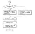
次に、図24〜図28を参照して、本発明の特徴的部分の1つである、上述した黒帯検出処理を含む黒帯検出部2および画像処理部3における入力映像信号のアスペクト比調整処理について詳細に説明する。図24は、このアスペクト調整処理を流れ図で表したものである。
Next, referring to FIGS. 24 to 28, the aspect ratio of the input video signal in the black
まず、黒帯検出部2内の信号種別判別部221が、入力映像信号6の種別を判別し(ステップS0)、判別結果Soutを検出部23および画像処理部3内の演算部31へ出力する。
First, the signal
次いで、黒帯検出部2が、この信号種別判別結果Soutおよび入力映像信号の輝度信号Yinに基づいて、図11(および図12〜図23)に示した一連の黒帯検出処理S11〜S18を行い(ステップS1)、黒帯検出結果Koutを演算部31へ出力する。
Next, the black
ここで、この黒帯検出処理S1では、図16,図17,図19および図20で示した境界判定処理1,2中のステップS126,S129,S146,S149では、計測領域64B内にブランキング領域60を含む黒帯領域のみが存在するのか否かを判断する際に、例えば図25(A)〜(C)にそれぞれ示したようにして判断する。すなわち、例えばこの図のように映像領域62の上側において黒帯領域61A(ブランキング領域60を含む)のみが存在するか否かを判断する際には、水平バックポーチ長Hbpおよび水平フロントポーチ長Hfpの値も利用して判断する。
Here, in the black belt detection process S1, blanking is performed in the
具体的には、例えば図25(A)に示したように、水平バックポーチ長Hbpおよび水平フロントポーチ長Hfpがいずれも計測領域64Bの水平方向の幅(この場合、基準領域64Aの水平方向の幅)と一致している場合には、この計測領域64B内には映像領域62や黒帯領域内の字幕などは存在せず、黒帯領域のみであると判断する。
Specifically, for example, as shown in FIG. 25A, the horizontal back porch length Hbp and the horizontal front porch length Hfp are both the horizontal width of the
また、例えば図25(B)に示したように、計測領域64B内に映像領域62が存在する場合には、測定結果による水平バックポーチ長Hbpおよび水平フロントポーチ長Hfpと、予め設定された水平バックポーチ長Hbp0および水平フロントポーチ長Hfp0とが一致するか否かによって映像領域62が存在するか否かを判断する。具体的には、水平バックポーチ長Hbpと水平バックポーチ長Hbp0、および水平フロントポーチ長Hfpと水平フロントポーチ長Hfp0のうちの少なくとも一方が一致すれば、映像領域62が存在すると判断する。なお、図25(B)中に示したように、水平バックポーチ長Hbp0は、入力映像信号の種別から決定される水平長Hbp1と計測領域64Bを設定する際に決定される水平長Hbp2との差により決定され(Hbp0=Hbp1−Hbp2)、水平フロントポーチ長Hfp0は、入力映像信号の種別から決定される水平長Hfp1と計測領域64Bを設定する際に決定される水平長Hfp2との差により決定される(Hfp0=Hfp1−Hfp2)。
For example, as shown in FIG. 25B, when the
さらに、例えば図25(C)に示したように、計測領域64B内には映像領域62が存在しないが(黒帯領域61Aのみが存在する)、黒帯領域61A内に字幕63Bが存在する場合には、測定結果による水平バックポーチ長Hbpおよび水平フロントポーチ長Hfpが、予め設定された水平バックポーチ長Hbp0および水平フロントポーチ長Hfp0と比べて大きいため、基本的にはまず映像領域62が存在しないと判断する。字幕63Bの領域を含めて映像領域が存在すると判断すると、後述するアスペクト比の調整の際に誤った調整がなされてしまうことになるからである。ただし、字幕63が欠落しないようにするため、測定結果による水平バックポーチ長Hbpおよび水平フロントポーチ長Hfpに加え、測定結果による垂直バックポーチ長Vbpや垂直フロントポーチ長Vfpを用いて(図25(C)の場合、垂直バックポーチ長Vbpを用いて)、字幕63の位置を求めるようにする。なお、字幕63Bは単位フレームによって表示されたりされなかったりするので、黒帯検出処理によって検出が確定するまでの間で垂直バックポーチ長Vbpや垂直フロントポーチ長Vfpが一番小さくなった値を、字幕63Bの位置とするようになっている。
Further, for example, as shown in FIG. 25C, the
このようにして、計測領域64B内にブランキング領域60を含む黒帯領域のみが存在するのか否かを判断する際に、水平バックポーチ長Hbpや水平フロントポーチ長Hfpの値も利用して判断しているので、映像領域62の存在だけでなく、黒帯領域内の字幕63Bの存在の有無も判断できるようになっている。
Thus, when determining whether or not only the black belt region including the blanking
図24の説明に戻り、次いで画像処理部3内の演算部31が、上述の黒帯検出部2による黒帯検出処理の結果(黒帯検出結果Kout)および信号種別判別部21による入力映像信号の種別判別結果Soutに基づいて、入力映像信号であるYUV信号(Yin,Uin,Vin)の拡大または縮小の比率を演算して求める処理(拡大縮小比率演算処理)を行う(ステップS2)。具体的には、図26および図27の流れ図で示したような処理がなされる。
Returning to the description of FIG. 24, the
まず、演算部31は黒帯検出結果Kout(および種別判別結果Sout)を取得すると(ステップS201)、これらの結果に基づいて入力映像信号(Yin,Uin,Vin)内に黒帯領域が存在するか否かを判断する(ステップS202)。具体的には、種別判別結果Soutに基づく入力映像信号の水平バックポーチ長、水平フロントポーチ長、垂直バックポーチ長および垂直フロントポーチ長がそれぞれ、黒帯検出結果Koutに基づく水平バックポーチ長H1A、水平フロントポーチ長H1B、垂直バックポーチ長V1Aおよび垂直フロントポーチ長V1Bと一致するか否かにより、黒帯領域が存在するか否かを判断する。例えば入力映像信号内に黒帯領域が存在しない場合には、例えば図28に示したように、これらの値が一致することとなるからである。
First, when the
このようにしてステップS202において黒帯領域が存在しないと判断された場合には(ステップS202:N)、演算部31は、信号種別結果Soutに基づいて、映像領域の表示サイズに応じた水平方向および垂直方向の拡大縮小比率を演算する(ステップS204,S205)。そしてこの演算結果Coutを拡大縮小部32へ出力する(ステップS205)ことにより、拡大縮小比率演算処理が終了となる。
In this way, when it is determined in step S202 that there is no black belt region (step S202: N), the
一方、ステップS202において黒帯領域が存在すると判断された場合(ステップS202:Y)、次に演算部31は、現在の黒帯検出結果Koutが前回の単位フレームにおける結果から変動があるか否か(水平バックポーチ長H1A、水平フロントポーチ長H1B、垂直バックポーチ長V1Aおよび垂直フロントポーチ長V1Bなどの値が変化しているか否か)を判断する(ステップS206)。前回の結果から変動がないと判断された場合には(ステップS206:N)、拡大縮小比率を変える必要はなく、そのまま維持すればよいことから、拡大縮小比率演算処理が終了となる。
On the other hand, when it is determined in step S202 that a black band region exists (step S202: Y), the
一方、ステップS206において、前回の結果から変動していると判断された場合には(ステップS206:Y)、次に演算部31は、黒帯検出結果Koutに基づいて映像領域に変動があるか否か(例えば、図12(A),(B)で示した映像領域の幅H2,V2が変化しているか否か)を判断する(ステップS207)。映像領域に変動がないと判断された場合(ステップS207:N)、次に演算部31は、黒帯検出結果Koutに基づいて字幕領域が拡大しているか否かを判断する(ステップS209)。具体的には、前述の図12(A)に示したような、垂直バックポーチを含めたOSD63Aの最上端までの長さV0Aや、入力映像信号6の垂直フロントポーチを含めた字幕63Bの最下端までの長さV0Bが小さくなっているか否かを判断する。これらの値により字幕領域が縮小しているまたは変化していないと判断された場合には(ステップS209:N)、拡大縮小比率を変える必要はなく、そのまま維持すればよいことから、拡大縮小比率演算処理が終了となる。
On the other hand, if it is determined in step S206 that there has been a change from the previous result (step S206: Y), then the
一方、ステップS207において映像領域に変動があると判断された場合(ステップS207:Y)、およびステップS209において字幕領域が拡大していると判断された場合には(ステップS209:Y)、次に演算部31は、黒帯検出結果Kout(具体的には、映像領域の幅H2,V2など)に基づいて、入力映像信号(Yin,Uin,Vin)のうちの黒帯領域を除いた映像領域のアスペクト比を算出する(ステップS208)。そして演算部31は、この算出したアスペクト比および黒帯検出結果Koutに基づいて、入力映像信号(Yin,Uin,Vin)における映像領域のアスペクト比を保ちつつ、表示サイズに応じて字幕が欠落しないように、水平方向および垂直方向の拡大縮小比率を演算して求める(ステップS210,S211)。これにより、拡大縮小比率演算処理が終了となる。
On the other hand, if it is determined in step S207 that there is a change in the video area (step S207: Y) and if it is determined in step S209 that the subtitle area is enlarged (step S209: Y), then Based on the black band detection result Kout (specifically, the video area widths H2, V2, etc.), the
具体的には、例えば図29(A)に示したように、入力映像信号6中の黒帯領域61A,61B内に字幕がないような場合には、視聴の際にこれら黒帯領域61A,61Bが邪魔にならないように、入力映像信号6のアスペクト比を保ちつつ、映像領域62のみが表示領域7となって表示部5の表示画面全体に表示されるように、入力映像信号6に対する拡大縮小(アスペクト比調整)がなされる。
Specifically, for example, as shown in FIG. 29A, when there are no captions in the
一方、例えば図29(B)に示したように、黒帯領域61A,61B内にそれぞれ字幕63B1,63B2があるような場合には、これら字幕63B1,63B2が欠落しないように、入力映像信号6のアスペクト比を保ちつつ拡大縮小がなされる。また、例えば図29(C)に示したように、一対の黒帯領域のうちの一方(この場合、上下の黒帯領域61A,61Bのうちの下側の黒帯領域61B)のみに字幕(字幕63B)があるような場合には、拡大縮小部32によって字幕63Bが欠落しないように拡大または縮小された映像信号に対し、位置調整部33によって、他方の黒帯領域(この場合、上側の黒帯領域61A)が表示領域7に含まれないように、図中の矢印P1のように位置調整がなされる。
On the other hand, for example, as shown in FIG. 29B, when there are subtitles 63B1 and 63B2 in the
なお、表示部5の表示画面の一部にサブウィンドウが設けられ、このサブウィンドウ内に映像信号を表示するような場合には、画像処理部3は、サブウィンドウ内の全面に入力映像信号が表示されるように、アスペクト比調整処理を行うようにすればよい。
When a sub window is provided in a part of the display screen of the
次いで、図24に戻り、拡大縮小部32は、演算部31による演算結果Cout(拡大縮小比率)に基づいて、入力映像信号であるYUV信号(Yin,Uin,Vin)の拡大または縮小を行う(ステップS3)。次に、位置調整部33が、この拡大縮小部32によって黒帯領域内の字幕が欠落しないように拡大または縮小された映像信号に対し、例えば前述の図29(C)に示したような位置調整を行う(ステップS4)。そして最後にアスペクト比の調整処理を終了するか否かが判断され(ステップS5)、まだ終了しないと判断された場合には(ステップS5:N)、ステップS0〜S4の処理を繰り返し、終了すると判断された場合には(ステップS5:Y)、アスペクト比調整処理が終了となる。
Next, returning to FIG. 24, the enlargement /
このようにして、黒帯検出部2による黒帯検出結果Koutに基づいて、画像処理部3による画像処理(入力映像信号のアスペクト比調整処理)がなされる。
In this way, image processing (aspect ratio adjustment processing of the input video signal) is performed by the
以上のように、本実施の形態では、計測部22が、入力映像信号6であるYUV信号(Yin,Uin,Vin)のうちの計測領域64A,64Bについて、画素ごとにしきい値Vt未満の信号レベルか否かの計測を単位フレーム期間内に行うようにすると共に、検出部23が、この計測結果に基づいて入力映像信号6に含まれる黒帯領域を検出するようにしたので、従来と比べ、入力映像信号に含まれる黒帯領域をより短時間に検出することが可能となる。
As described above, in the present embodiment, the
また、計測部22および検出部23が、画素ごとになされるしきい値Vt未満の信号レベルか否かの計測結果から黒帯領域と映像領域との境界を検出すると共に、検出されたか否かに応じて前回の増減幅の2分の1のものを新たな増減幅として前回の計測領域に加減算して新たな計測領域を設定し、この新たな計測領域について逐次計測を行うと共にその計測結果に基づいて黒帯領域を検出するようにしたので、入力映像信号6に含まれる黒帯領域をさらに短時間に検出することが可能となる。
Further, the
また、検出部23内の検出判定部237が、黒帯領域の幅が変化しているか否かを判断すると共に、変化している場合には2つの黒帯検出領域の幅のうちどちらか一方のみが大きく変化しているかどうかを判断するようにしたので、一方のみが大きく変化している場合には映像信号が暗いシーン等であるためだと判断することができ、黒帯領域の誤検出を防ぐことができる。よって、そのような誤検出を防ぎ、精度の高い黒帯検出を行うことが可能となる。
In addition, the
また、上記のように精度の高い黒帯検出を短時間に行うことができるので、画像処理部3は、その黒帯検出結果Koutを用いて最適な画像処理を短時間に行うことが可能となる。
In addition, since black band detection with high accuracy can be performed in a short time as described above, the
また、入力映像信号のうちの黒帯領域を除いた映像領域のアスペクト比を保ちつつ、入力映像信号の拡大または縮小をすることができる。よって、そのような拡大縮小処理がなされた映像信号を用いて映像表示を行うことにより、従来と比べ非常に見やすい映像を表示することが可能となる。 Further, the input video signal can be enlarged or reduced while maintaining the aspect ratio of the video area excluding the black belt area in the input video signal. Therefore, it is possible to display a video that is much easier to view than before by performing video display using the video signal that has been subjected to such enlargement / reduction processing.
また、黒帯領域内の字幕の有無も考慮して拡大縮小を行うようにしたので、字幕を欠落させることなく、黒帯領域を含む映像を表示させることが可能となる。 In addition, since the enlargement / reduction is performed in consideration of the presence / absence of subtitles in the black belt region, it is possible to display an image including the black belt region without dropping the subtitles.
また、位置調整部33により、黒帯領域内の字幕の有無などに応じて、映像信号の表示位置を調整することができる。よって、よりみやすい映像を提供することが可能となる。
In addition, the display position of the video signal can be adjusted by the
さらに、黒帯検出部2による高速な黒帯検出結果Koutを用いて画像処理を行っているので、入力映像信号の変化に追従して拡大縮小比率の再計算を行うことができ、リアルタイムにアスペクト比の調整を行うことが可能となる。
Furthermore, since image processing is performed using the high-speed black band detection result Kout by the black
以上、実施の形態を挙げて本発明を説明したが、本発明はこの実施の形態に限定されるものではなく、種々の変形が可能である。 While the present invention has been described with reference to the embodiment, the present invention is not limited to this embodiment, and various modifications can be made.
例えば、上記実施の形態では、映像領域の上下に黒帯領域が存在するシネマスコープ方式の映像信号や、映像領域の左右に黒帯領域が存在する再度パネル方式の映像信号における黒帯検出について説明したが、そのような黒帯検出を組み合わせて、映像領域の上下および左右の4方向について黒帯領域を検出するようにすることも可能である。 For example, in the above-described embodiment, black band detection is described in a cinemascope type video signal in which black band areas exist above and below the video area, and in a panel type video signal in which black band areas exist on both sides of the video area. However, it is also possible to detect the black belt region in the four directions of the upper and lower sides and the left and right of the video region by combining such black belt detection.
また、上記実施の形態では、黒帯検出部2による黒帯検出結果Koutを用いて画像処理部3が入力映像信号のアスペクト比調整処理を行う場合について説明したが、黒帯検出結果Koutを用いた画像処理はこれには限られず、例えばコントラスト調整処理や輝度調整処理などに適用することも可能である。このような画像処理に適用した場合も、黒帯検出部2による短時間かつ高精度な黒帯検出により、最適な画像処理を短時間に行うことが可能となる。
In the above embodiment, the case where the
また、上記実施の形態では、YUV信号が入力される場合の映像表示装置について説明したが、本発明は、例えばPC入力の場合のように、RGB信号が直接入力されるような映像表示装置などにも適用することが可能である。なお、そのようにRGB信号を直接入力する場合、マトリクス変換をする必要がなくなるので、マトリクス回路41は不要となる。
In the above embodiment, the video display apparatus when the YUV signal is input has been described. However, the present invention is an image display apparatus in which the RGB signal is directly input as in the case of the PC input, for example. It is also possible to apply to. Note that when the RGB signals are directly input in this way, it is not necessary to perform matrix conversion, so that the
さらに、上記実施の形態では、映像表示装置の一具体例としてTV装置を挙げて説明したが、本発明の映像表示装置は、この他にもPDA(Personal Digital Assistants)や携帯電話などにも適用することが可能である。 Furthermore, in the above embodiment, the TV apparatus has been described as a specific example of the video display apparatus. However, the video display apparatus of the present invention is also applicable to PDAs (Personal Digital Assistants), cellular phones, and the like. Is possible.
11…チューナ、12…Y/C分離回路、13…クロマデコーダ、14…スイッチ、2…黒検出部、21…信号種別判定部、22…計測部、221…信号レベル比較部、222…計測結果出力部、23…検出部、230…黒帯判定部、231…基準領域設定部、232…増減幅初期値設定部、233…増減幅設定部、234…境界判定部、235…再検出回数設定部、236…下限値設定部、237…検出判定部、238…計測領域設定部、239…しきい値設定部、3…画像処理部、31…演算部、32…拡大縮小部、33…位置調整部、41…マトリクス回路、42…トライバ、5…表示部、6…入力映像信号、60…ブランキング領域、61A,61B,65A,65B…黒帯領域、62,66…映像領域、62V,H2,V2…映像領域の幅、63A…OSD、63B,63B1,63B2…字幕、64A…計測領域(基準領域)、64B,64B1〜B4…計測領域、64H,64V…増減幅、64H1,64H2…水平方向計測区間、64V1,64V2…垂直方向計測区間、7…表示領域、Y1,Y2,Yin,Yout…輝度信号、C1…色信号、U1,U2,Uin,Uout,V1,V2,Vin,Vout…色差信号、Rout,Gout,Bout…RGB信号、Sout…信号種別判別結果、Kout…黒帯検出結果、Cout…演算結果、Mout…計測結果、Vt…しきい値、Hbp…水平バックポーチ長、Hfp…水平フロントポーチ長、Vbp…垂直バックポーチ長、Vfp…垂直フロントポーチ長、Hsync…水平同期信号、Vsync…垂直同期信号、Clock…クロック信号、H_act…水平アクティブ信号、V_act…垂直アクティブ信号、Hbp_cnt…水平バックポーチ用カウンタ出力、Hfp_cnt…水平フロントポーチ用カウンタ出力、Vbp_cnt…垂直バックポーチ用カウンタ出力、Vfp_cnt…垂直フロントポーチ用カウンタ出力、Hbp_lat…水平バックポーチ用ラッチ出力、Hfp_lat…水平フロントポーチ用ラッチ出力、Vbp_lat…垂直バックポーチ用ラッチ出力、Vfp_lat…垂直フロントポーチ用ラッチ出力、Hbp_out…水平バックポーチ長出力、Hfp_out…水平フロントポーチ長出力、Vbp_out…垂直バックポーチ長出力、Vfp_out…垂直フロントポーチ長出力。
DESCRIPTION OF SYMBOLS 11 ... Tuner, 12 ... Y / C separation circuit, 13 ... Chroma decoder, 14 ... Switch, 2 ... Black detection part, 21 ... Signal type determination part, 22 ... Measurement part, 221 ... Signal level comparison part, 222 ... Measurement result Output unit, 23 ... detection unit, 230 ... black band determination unit, 231 ... reference area setting unit, 232 ... increase / decrease width initial value setting unit, 233 ... increase / decrease width setting unit, 234 ... boundary determination unit, 235 ... redetection count setting 236 ... Lower
Claims (25)
前記計測手段の計測結果に基づいて、前記入力映像信号に含まれる黒帯領域を検出する黒帯検出手段と
を備えたことを特徴とする映像信号処理装置。 Measuring means for measuring, for each pixel, whether or not the signal level is less than a set threshold within a unit frame period for a specified measurement region of the input video signal;
A video signal processing apparatus comprising: black band detection means for detecting a black band region included in the input video signal based on a measurement result of the measurement means.
ことを特徴とする請求項1に記載の映像信号処理装置。 The video signal processing apparatus according to claim 1, further comprising threshold setting means for setting the threshold.
ことを特徴とする請求項1に記載の映像信号処理装置。 The black belt detection means detects the number of pixels that are continuously present from the edge of the measurement area and less than a threshold value, and performs this detection process along the edge of the display area. The video signal processing apparatus according to claim 1, wherein the width of the black belt region is determined based on a minimum value of the number of pixels.
計測区間を増減する際の増減幅を設定する増減幅設定手段と、
前記基準領域と前記増減幅とに基づいて前記計測領域を設定する計測領域設定手段とを備えた
ことを特徴とする請求項1に記載の映像信号処理装置。 A reference area setting means for setting a reference area to be a measurement reference;
Increase / decrease setting means for setting the increase / decrease width when increasing / decreasing the measurement section,
The video signal processing apparatus according to claim 1, further comprising a measurement area setting unit that sets the measurement area based on the reference area and the increase / decrease width.
前記計測領域設定手段は、前記黒帯検出手段によって前記計測手段の計測結果から黒帯領域と映像領域との境界が検出されたか否かに応じて、前回の計測領域に対して前記新たな増減幅の加減算を行うことにより、新たな計測領域を設定し直し、
前記計測手段は、新たな計測領域について計測を行う
ことを特徴とする請求項4に記載の映像信号処理装置。 The increase / decrease setting means resets half of the previous increase / decrease as a new increase / decrease,
The measurement area setting means performs the new increase / decrease with respect to the previous measurement area depending on whether or not a boundary between the black band area and the video area is detected from the measurement result of the measurement means by the black band detection means. By adding / subtracting the width, a new measurement area is set again,
The video signal processing apparatus according to claim 4, wherein the measurement unit measures a new measurement region.
ことを特徴とする請求項4に記載の映像信号処理装置。 The video signal processing apparatus according to claim 4, wherein the measurement unit performs measurement in parallel in two directions of a horizontal direction and a vertical direction in the measurement region.
前記黒帯検出手段は、前記計測領域設定手段により設定された新たな計測領域についての計測結果に基づいて、前記入力映像信号に含まれる上端の黒帯領域を検出する
ことを特徴とする請求項6に記載の映像信号処理装置。 The measurement area setting means sets the horizontal end positions and the vertical upper end position in the measurement area as the horizontal end positions and the vertical upper end position in the reference area, while initializing the lower end position in the measurement area. The value is set to a position obtained by adding the initial value of the increase / decrease width from the upper end position in the reference area, and a new measurement area is reset by sequentially performing addition / subtraction of the increase / decrease width with respect to the lower end position in the measurement area. ,
The black band detection unit detects an upper black band region included in the input video signal based on a measurement result of a new measurement region set by the measurement region setting unit. 6. The video signal processing apparatus according to 6.
前記黒帯検出手段は、前記計測領域設定手段により設定された新たな計測領域についての計測結果に基づいて、前記入力映像信号に含まれる下端の黒帯領域を検出する
ことを特徴とする請求項6に記載の映像信号処理装置。 The measurement area setting means sets the horizontal end positions and the vertical lower end position in the measurement area to the horizontal end positions and the vertical lower end position in the reference area, and sets the initial upper end position in the measurement area. The value is set to a position obtained by subtracting the initial value of the increase / decrease width from the lower end position in the reference area, and a new measurement area is reset by sequentially adding / subtracting the increase / decrease width to the upper end position in the measurement area. ,
The black band detecting unit detects a black band region at a lower end included in the input video signal based on a measurement result of a new measurement region set by the measurement region setting unit. 6. The video signal processing apparatus according to 6.
前記黒帯検出手段は、前記計測領域設定手段により設定された新たな計測領域についての計測結果に基づいて、前記入力映像信号に含まれる左端の黒帯領域を検出する
ことを特徴とする請求項6に記載の映像信号処理装置。 The measurement area setting means sets the vertical end positions and the horizontal left end position in the measurement area to the vertical end positions and the horizontal left end position in the reference area, and sets the initial right end position in the measurement area. The value is set to a position obtained by adding the initial value of the increase / decrease width from the left end position in the reference area, and a new measurement area is reset by sequentially adding / subtracting the increase / decrease width to the right end position in the measurement area. ,
The black band detection unit detects a black band region at a left end included in the input video signal based on a measurement result of a new measurement region set by the measurement region setting unit. 6. The video signal processing apparatus according to 6.
前記黒帯検出手段は、前記計測領域設定手段により設定された新たな計測領域についての計測結果に基づいて、前記入力映像信号に含まれる右端の黒帯領域を検出する
ことを特徴とする請求項6に記載の映像信号処理装置。 The measurement area setting means sets the vertical end positions and the horizontal right end position in the measurement area to the vertical end positions and the horizontal right end position in the reference area, while setting the initial left end position in the measurement area. The value is set to a position obtained by subtracting the initial value of the increase / decrease width from the right end position in the reference area, and a new measurement area is reset by sequentially adding / subtracting the increase / decrease width to the left end position in the measurement area. ,
The black band detection unit detects a right black band region included in the input video signal based on a measurement result of a new measurement region set by the measurement region setting unit. 6. The video signal processing apparatus according to 6.
ことを特徴とする請求項1に記載の映像信号処理装置。 An image processing means for setting a correction area of the input video signal based on a detection result of the black belt detection means and performing predetermined image processing on the input video signal in the set correction area is provided. The video signal processing apparatus according to claim 1.
計測の基準となる基準領域を設定する基準領域設定手段と、
計測区間を増減する際の増減幅を設定する増減幅設定手段と、
前記基準領域と前記増減幅とに基づいて前記計測領域を設定する計測領域設定手段と、
前記計測手段の計測結果に基づいて、前記入力映像信号に含まれる黒帯領域を検出する黒帯検出手段と
を備え、
前記増減幅設定手段は、前回の増減幅の2分の1を新たな増減幅として設定し直し、
前記計測領域設定手段は、前記黒帯検出手段によって前記計測手段の計測結果から黒帯領域と映像領域との境界が検出されたか否かに応じて、前回の計測領域に対して前記新たな増減幅の加減算を行うことにより、新たな計測領域を設定し直し、
前記計測手段は、新たな計測領域について計測を行う
ことを特徴とする映像信号処理装置。 Measuring means for measuring, for each pixel, whether or not the signal level is less than a set threshold for a specified measurement region of the input video signal;
A reference area setting means for setting a reference area to be a measurement reference;
Increase / decrease setting means for setting the increase / decrease width when increasing / decreasing the measurement section,
Measurement area setting means for setting the measurement area based on the reference area and the increase / decrease width;
A black band detecting means for detecting a black band region included in the input video signal based on a measurement result of the measuring means;
The increase / decrease setting means resets half of the previous increase / decrease as a new increase / decrease,
The measurement area setting means performs the new increase / decrease with respect to the previous measurement area depending on whether or not a boundary between the black band area and the video area is detected from the measurement result of the measurement means by the black band detection means. By adding / subtracting the width, a new measurement area is set again,
The said measurement means measures about a new measurement area | region. The video signal processing apparatus characterized by the above-mentioned.
ことを特徴とする請求項12に記載の映像信号処理装置。 The black belt detection means detects the number of pixels that are continuously present from the edge of the measurement area and less than a threshold value, and performs this detection process along the edge of the display area. The video signal processing apparatus according to claim 12, wherein the minimum value of the number of pixels is determined as the width of the black belt region.
ことを特徴とする請求項12に記載の映像信号処理装置。 The video signal processing apparatus according to claim 12, wherein the measurement unit performs measurement in parallel in two directions of a horizontal direction and a vertical direction in the measurement region.
ことを特徴とする請求項12に記載の映像信号処理装置。 An image processing means for setting a correction area of the input video signal based on a detection result of the black belt detection means and performing predetermined image processing on the input video signal in the set correction area is provided. The video signal processing device according to claim 12.
前記計測手段の計測結果に基づいて、前記入力映像信号に含まれる黒帯領域を検出する黒帯検出手段と、
前記黒帯検出手段の検出結果を基に映像表示を行う表示手段と
を備えたことを特徴とする映像信号表示装置。 Measuring means for measuring, for each pixel, whether or not the signal level is less than a set threshold within a unit frame period for a specified measurement region of the input video signal;
Based on the measurement result of the measurement means, a black belt detection means for detecting a black belt region included in the input video signal;
A video signal display device comprising: display means for displaying video based on a detection result of the black belt detection means.
計測区間を増減する際の増減幅を設定する増減幅設定手段と、
前記基準領域と前記増減幅とに基づいて前記計測領域を設定する計測領域設定手段とを備え、
前記増減幅設定手段は、前回の増減幅の2分の1を新たな増減幅として設定し直し、
前記計測領域設定手段は、前記黒帯検出手段によって前記計測手段の計測結果から黒帯領域と映像領域との境界が検出されたか否かに応じて、前回の計測領域に対して前記新たな増減幅の加減算を行うことにより、新たな計測領域を設定し直し、
前記計測手段は、新たな計測領域について計測を行う
ことを特徴とする請求項16に記載の映像表示装置。 A reference area setting means for setting a reference area to be a measurement reference;
Increase / decrease setting means for setting the increase / decrease width when increasing / decreasing the measurement section,
A measurement area setting means for setting the measurement area based on the reference area and the increase / decrease width;
The increase / decrease setting means resets half of the previous increase / decrease as a new increase / decrease,
The measurement area setting means performs the new increase / decrease with respect to the previous measurement area depending on whether or not a boundary between the black band area and the video area is detected from the measurement result of the measurement means by the black band detection means. By adding / subtracting the width, a new measurement area is set again,
The video display device according to claim 16, wherein the measurement unit performs measurement for a new measurement region.
前記表示手段は、前記画像処理後の入力映像信号に基づいて映像表示を行う
ことを特徴とする請求項16に記載の映像表示装置。 An image processing means for setting a correction area of the input video signal based on a detection result of the black belt detection means and performing predetermined image processing on the input video signal in the set correction area,
The video display apparatus according to claim 16, wherein the display unit performs video display based on the input video signal after the image processing.
計測の基準となる基準領域を設定する基準領域設定手段と、
計測区間を増減する際の増減幅を設定する増減幅設定手段と、
前記基準領域と前記増減幅とに基づいて前記計測領域を設定する計測領域設定手段と、
前記計測手段の計測結果に基づいて、前記入力映像信号に含まれる黒帯領域を検出する黒帯検出手段と、
前記黒帯検出手段の検出結果を基に映像表示を行う表示手段と
を備え、
前記増減幅設定手段は、前回の増減幅の2分の1を新たな増減幅として設定し直し、
前記計測領域設定手段は、前記黒帯検出手段によって前記計測手段の計測結果から黒帯領域と映像領域との境界が検出されたか否かに応じて、前回の計測領域に対して前記新たな増減幅の加減算を行うことにより、新たな計測領域を設定し直し、
前記計測手段は、新たな計測領域について計測を行う
ことを特徴とする映像表示装置。 Measuring means for measuring, for each pixel, whether or not the signal level is less than a set threshold for a specified measurement region of the input video signal;
A reference area setting means for setting a reference area to be a measurement reference;
Increase / decrease setting means for setting the increase / decrease width when increasing / decreasing the measurement section,
Measurement area setting means for setting the measurement area based on the reference area and the increase / decrease width;
Based on the measurement result of the measurement means, a black belt detection means for detecting a black belt region included in the input video signal;
Display means for displaying an image based on the detection result of the black belt detection means,
The increase / decrease setting means resets half of the previous increase / decrease as a new increase / decrease,
The measurement area setting means performs the new increase / decrease with respect to the previous measurement area depending on whether or not a boundary between the black band area and the video area is detected from the measurement result of the measurement means by the black band detection means. By adding / subtracting the width, a new measurement area is set again,
The video display device characterized in that the measuring means measures a new measurement area.
前記表示手段は、前記画像処理後の入力映像信号に基づいて映像表示を行う
ことを特徴とする請求項19に記載の映像表示装置。 An image processing means for setting a correction area of the input video signal based on a detection result of the black belt detection means and performing predetermined image processing on the input video signal in the set correction area,
The video display apparatus according to claim 19, wherein the display unit performs video display based on the input video signal after the image processing.
計測結果に基づいて前記入力映像信号に含まれる黒帯領域を検出し、
前記黒帯領域の検出結果を基に映像表示を行う
ことを特徴とする映像表示方法。 For the specified measurement area of the input video signal, measure whether the signal level is less than the set threshold value for each pixel within the unit frame period,
Detecting a black belt area included in the input video signal based on the measurement result,
A video display method, wherein video display is performed based on a detection result of the black belt region.
計測区間を増減する際の増減幅を設定し、
前記基準領域と前記増減幅とに基づいて前記計測領域を設定し、
前記増減幅を設定する際に、前回の増減幅の2分の1を新たな増減幅として設定し直し、
前記計測領域を設定する際に、前記計測結果から黒帯領域と映像領域との境界が検出されたか否かに応じて、前回の計測領域に対して前記新たな増減幅の加減算を行うことにより、新たな計測領域を設定し直し、
前記計測を行う際に、新たな計測領域について計測を行う
ことを特徴とする請求項21に記載の映像表示方法。 Set the reference area to be the measurement reference,
Set the increment / decrement range when increasing / decreasing the measurement section,
Set the measurement area based on the reference area and the increase / decrease width,
When setting the increase / decrease width, reset half of the previous increase / decrease width as a new increase / decrease width,
When setting the measurement area, by adding or subtracting the new increase / decrease width with respect to the previous measurement area, depending on whether or not a boundary between the black belt area and the video area is detected from the measurement result. , Set a new measurement area,
The video display method according to claim 21, wherein when the measurement is performed, a new measurement area is measured.
ことを特徴とする請求項21に記載の映像表示方法。 Based on the detection result of the black belt region, a correction region of the input video signal is set and predetermined image processing is performed on the input video signal in the set correction region, and the input video signal after the image processing is performed The video display method according to claim 21, wherein video display is performed based on the video.
計測の基準となる基準領域を設定し、
計測区間を増減する際の増減幅を設定し、
前記基準領域と前記増減幅とに基づいて前記計測領域を設定し、
計測結果に基づいて前記入力映像信号に含まれる黒帯領域を検出し、
前記黒帯領域の検出結果を基に映像表示を行うと共に、
前記増減幅を設定する際に、前回の増減幅の2分の1を新たな増減幅として設定し直し、
前記計測領域を設定する際に、前記計測結果から黒帯領域と映像領域との境界が検出されたか否かに応じて、前回の計測領域に対して前記新たな増減幅の加減算を行うことにより、新たな計測領域を設定し直し、
前記計測を行う際に、新たな計測領域について計測を行う
ことを特徴とする映像表示方法。 For each specified pixel in the input video signal, measure whether or not the signal level is below the set threshold,
Set the reference area to be the measurement reference,
Set the increment / decrement range when increasing / decreasing the measurement section,
Set the measurement area based on the reference area and the increase / decrease width,
Detecting a black belt area included in the input video signal based on the measurement result,
While displaying video based on the detection result of the black belt region,
When setting the increase / decrease width, reset half of the previous increase / decrease width as a new increase / decrease width,
When setting the measurement area, by adding or subtracting the new increase / decrease width with respect to the previous measurement area, depending on whether or not a boundary between the black belt area and the video area is detected from the measurement result. , Set a new measurement area,
A video display method characterized by measuring a new measurement area when performing the measurement.
ことを特徴とする請求項24に記載の映像表示方法。 Based on the detection result of the black belt region, a correction region of the input video signal is set and predetermined image processing is performed on the input video signal in the set correction region, and the input video signal after the image processing is performed The video display method according to claim 24, wherein video display is performed based on the video.
Priority Applications (3)
| Application Number | Priority Date | Filing Date | Title |
|---|---|---|---|
| JP2006159316A JP2007329700A (en) | 2006-06-08 | 2006-06-08 | Video signal processor, video display apparatus and video display method |
| US11/810,962 US8098328B2 (en) | 2006-06-08 | 2007-06-06 | Image signal processing apparatus, image display and image display method |
| CN200710110277XA CN101087380B (en) | 2006-06-08 | 2007-06-08 | Image signal processing apparatus, image display and image display method |
Applications Claiming Priority (1)
| Application Number | Priority Date | Filing Date | Title |
|---|---|---|---|
| JP2006159316A JP2007329700A (en) | 2006-06-08 | 2006-06-08 | Video signal processor, video display apparatus and video display method |
Publications (2)
| Publication Number | Publication Date |
|---|---|
| JP2007329700A true JP2007329700A (en) | 2007-12-20 |
| JP2007329700A5 JP2007329700A5 (en) | 2009-07-16 |
Family
ID=38918785
Family Applications (1)
| Application Number | Title | Priority Date | Filing Date |
|---|---|---|---|
| JP2006159316A Pending JP2007329700A (en) | 2006-06-08 | 2006-06-08 | Video signal processor, video display apparatus and video display method |
Country Status (3)
| Country | Link |
|---|---|
| US (1) | US8098328B2 (en) |
| JP (1) | JP2007329700A (en) |
| CN (1) | CN101087380B (en) |
Cited By (2)
| Publication number | Priority date | Publication date | Assignee | Title |
|---|---|---|---|---|
| WO2010116457A1 (en) * | 2009-03-30 | 2010-10-14 | Necディスプレイソリューションズ株式会社 | Video display device and video processing method |
| JP2020508611A (en) * | 2017-02-27 | 2020-03-19 | インターデジタル シーイー パテント ホールディングス | Method and apparatus for reusing black border area of digital TV screen |
Families Citing this family (17)
| Publication number | Priority date | Publication date | Assignee | Title |
|---|---|---|---|---|
| TWI466093B (en) * | 2007-06-26 | 2014-12-21 | Apple Inc | Management techniques for video playback |
| TWI479891B (en) * | 2007-06-26 | 2015-04-01 | Apple Inc | Dynamic backlight adaptation |
| US8766902B2 (en) * | 2007-12-21 | 2014-07-01 | Apple Inc. | Management techniques for video playback |
| KR20110024642A (en) * | 2009-09-02 | 2011-03-09 | 삼성전자주식회사 | Display apparatus and control method thereof |
| CN102639423B (en) * | 2009-12-15 | 2015-01-21 | 三菱电机株式会社 | Display control device for an elevator |
| US9143767B2 (en) * | 2010-06-01 | 2015-09-22 | Intel Corporation | Method and apparatus for adaptive stable image timing in stereoscopic 3D systems |
| US8547481B2 (en) * | 2010-12-20 | 2013-10-01 | Texas Instruments Incorporated | Apparatus and method for black bar detection in digital TVs and set-top boxes |
| US8976292B2 (en) * | 2011-12-09 | 2015-03-10 | Texas Instruments Incorporated | Perceptual video quality improvement for videos containing black bars |
| CN103369205B (en) * | 2012-03-26 | 2016-11-16 | 宇龙计算机通信科技(深圳)有限公司 | Mobile terminal and method of video image processing |
| CN104915944B (en) * | 2014-03-14 | 2018-08-07 | 北京风行在线技术有限公司 | A kind of method and apparatus for determining the black surround location information of video |
| TWI542211B (en) * | 2014-04-29 | 2016-07-11 | 瑞昱半導體股份有限公司 | Circuit for generating horizontal synchronous signal of display and associated method |
| CN104363505B (en) * | 2014-11-17 | 2017-05-31 | 天脉聚源(北京)传媒科技有限公司 | A kind of method and device for showing broadcast interface |
| KR102308645B1 (en) | 2014-12-29 | 2021-10-05 | 삼성전자주식회사 | User termincal device and methods for controlling the user termincal device thereof |
| CN105573747B (en) * | 2015-12-10 | 2018-11-06 | 小米科技有限责任公司 | The test method and device of user interface |
| CN109005458B (en) * | 2018-09-27 | 2021-02-23 | 上海东方传媒技术有限公司 | Image screen-splash detection method and device |
| US11869222B2 (en) * | 2021-03-10 | 2024-01-09 | The United States Of America, As Represented By The Secretary Of The Navy | Geospatial data abstraction library (GDAL) conversion tool for data compression |
| CN113053324A (en) * | 2021-03-15 | 2021-06-29 | 生迪智慧科技有限公司 | Backlight control method, device, equipment, system and storage medium |
Citations (3)
| Publication number | Priority date | Publication date | Assignee | Title |
|---|---|---|---|---|
| JPH06175641A (en) * | 1992-12-04 | 1994-06-24 | Sony Corp | Character input display device |
| JPH0918797A (en) * | 1995-06-28 | 1997-01-17 | Sanyo Electric Co Ltd | Television receiver |
| JP2004186803A (en) * | 2002-11-29 | 2004-07-02 | Matsushita Electric Ind Co Ltd | Image display and method therefor |
Family Cites Families (32)
| Publication number | Priority date | Publication date | Assignee | Title |
|---|---|---|---|---|
| JPH0527736A (en) | 1991-07-18 | 1993-02-05 | Matsushita Electric Ind Co Ltd | Method and device for processing video signal |
| US5699123A (en) * | 1993-10-20 | 1997-12-16 | Victor Company Of Japan, Ltd. | Television receiver with an adjustable frame size |
| TW307971B (en) * | 1994-03-31 | 1997-06-11 | Matsushita Electric Ind Co Ltd | |
| JP3429842B2 (en) * | 1994-04-15 | 2003-07-28 | 松下電器産業株式会社 | Image information detection device for video signal |
| US6002797A (en) * | 1994-06-22 | 1999-12-14 | Hitachi, Ltd. | Apparatus for detecting position of featuring region of picture, such as subtitle or imageless part |
| TW344931B (en) * | 1994-12-08 | 1998-11-11 | Matsushita Electric Ind Co Ltd | Average luminance level detection apparatus and aspect ratio auto-discrimination apparatus for a television signal using the same |
| JP3501252B2 (en) * | 1995-06-16 | 2004-03-02 | 三菱電機株式会社 | Gradation correction device |
| EP0837602A3 (en) * | 1996-10-17 | 1999-10-06 | Kabushiki Kaisha Toshiba | Letterbox image detection apparatus |
| KR100261214B1 (en) * | 1997-02-27 | 2000-07-01 | 윤종용 | Histrogram equalization method and apparatus of a contrast expanding apparatus in image processing system |
| EP0913993A1 (en) * | 1997-10-28 | 1999-05-06 | Deutsche Thomson-Brandt Gmbh | Method and apparatus for automatic format detection in digital video picture |
| US6340992B1 (en) * | 1997-12-31 | 2002-01-22 | Texas Instruments Incorporated | Automatic detection of letterbox and subtitles in video |
| US6463102B1 (en) * | 1998-09-11 | 2002-10-08 | Harmonic, Inc. | Digital video compressor with border processor |
| US6262772B1 (en) * | 1998-11-23 | 2001-07-17 | Philips Electronics North America Corporation | Method and apparatus for preventing display screen burn-in |
| FR2793375A1 (en) * | 1999-05-06 | 2000-11-10 | Thomson Multimedia Sa | METHOD FOR DETECTING BLACK BANDS IN A VIDEO IMAGE |
| JP3492946B2 (en) * | 1999-07-29 | 2004-02-03 | 日本放送協会 | Image aspect ratio converter |
| JP4340821B2 (en) * | 1999-09-06 | 2009-10-07 | ソニー株式会社 | Video equipment and video display method |
| US7061552B1 (en) * | 2000-01-28 | 2006-06-13 | Sony Corporation | Method and apparatus to perform automatic digital convergence |
| JP4613403B2 (en) * | 2000-08-25 | 2011-01-19 | ソニー株式会社 | Image display apparatus and method |
| EP1408684A1 (en) * | 2002-10-03 | 2004-04-14 | STMicroelectronics S.A. | Method and system for displaying video with automatic cropping |
| JP3664251B2 (en) * | 2002-11-06 | 2005-06-22 | 船井電機株式会社 | Video output device |
| US7187415B2 (en) * | 2002-12-12 | 2007-03-06 | Ati Technologies, Inc. | System for detecting aspect ratio and method thereof |
| JP3819870B2 (en) * | 2003-04-25 | 2006-09-13 | 三洋電機株式会社 | Image display device |
| SG118191A1 (en) * | 2003-06-27 | 2006-01-27 | St Microelectronics Asia | Method and system for contrast enhancement of digital video |
| US7339627B2 (en) * | 2003-10-30 | 2008-03-04 | Broadcom Corporation | Method and system for automatic detection and display of aspect ratio |
| US7502513B2 (en) * | 2003-11-14 | 2009-03-10 | Lsi Corporation | Commercial detector with a start of active video detector |
| JP2005203933A (en) | 2004-01-14 | 2005-07-28 | Matsushita Electric Ind Co Ltd | Video-reproducing apparatus and video-reproducing method |
| EP1583364A1 (en) * | 2004-03-30 | 2005-10-05 | Matsushita Electric Industrial Co., Ltd. | Motion compensated interpolation of images at image borders for frame rate conversion |
| US7643091B2 (en) * | 2004-05-18 | 2010-01-05 | Harris Technology, Llc | Aspect ratio enhancement |
| KR100594806B1 (en) * | 2004-12-28 | 2006-06-30 | 삼성전자주식회사 | Display apparatus for detecting letter-box boundary and method for image display using the same |
| US7262811B2 (en) * | 2004-12-29 | 2007-08-28 | General Instrument Corporation | System and method for automatic zoom |
| US7262812B2 (en) * | 2004-12-30 | 2007-08-28 | General Instrument Corporation | Method for fine tuned automatic zoom |
| KR100834751B1 (en) * | 2005-01-19 | 2008-06-05 | 삼성전자주식회사 | Apparatus and method for extracting the image radio of received broadcast content |
-
2006
- 2006-06-08 JP JP2006159316A patent/JP2007329700A/en active Pending
-
2007
- 2007-06-06 US US11/810,962 patent/US8098328B2/en not_active Expired - Fee Related
- 2007-06-08 CN CN200710110277XA patent/CN101087380B/en not_active Expired - Fee Related
Patent Citations (3)
| Publication number | Priority date | Publication date | Assignee | Title |
|---|---|---|---|---|
| JPH06175641A (en) * | 1992-12-04 | 1994-06-24 | Sony Corp | Character input display device |
| JPH0918797A (en) * | 1995-06-28 | 1997-01-17 | Sanyo Electric Co Ltd | Television receiver |
| JP2004186803A (en) * | 2002-11-29 | 2004-07-02 | Matsushita Electric Ind Co Ltd | Image display and method therefor |
Cited By (4)
| Publication number | Priority date | Publication date | Assignee | Title |
|---|---|---|---|---|
| WO2010116457A1 (en) * | 2009-03-30 | 2010-10-14 | Necディスプレイソリューションズ株式会社 | Video display device and video processing method |
| JPWO2010116457A1 (en) * | 2009-03-30 | 2012-10-11 | Necディスプレイソリューションズ株式会社 | Video display device and video processing method |
| JP2020508611A (en) * | 2017-02-27 | 2020-03-19 | インターデジタル シーイー パテント ホールディングス | Method and apparatus for reusing black border area of digital TV screen |
| JP7009489B2 (en) | 2017-02-27 | 2022-01-25 | インターデジタル マディソン パテント ホールディングス, エスアーエス | Methods and equipment for reusing the black border area of digital TV screens |
Also Published As
| Publication number | Publication date |
|---|---|
| CN101087380A (en) | 2007-12-12 |
| US8098328B2 (en) | 2012-01-17 |
| CN101087380B (en) | 2011-08-03 |
| US20080007655A1 (en) | 2008-01-10 |
Similar Documents
| Publication | Publication Date | Title |
|---|---|---|
| JP5067599B2 (en) | Video signal processing device, video display device, and video display method | |
| JP2007329700A (en) | Video signal processor, video display apparatus and video display method | |
| JP4620163B2 (en) | Still subtitle detection apparatus, video device for displaying image including still subtitle, and method for processing image including still subtitle | |
| US7170562B2 (en) | Apparatus and method for deinterlace video signal | |
| US7961253B2 (en) | Method of processing fields of images and related device for data lines similarity detection | |
| US20080028431A1 (en) | Image processing apparatus, display apparatus and image processing method | |
| US20190043233A1 (en) | Adaptive high dynamic range (hdr) tone mapping with overlay indication | |
| KR20040015965A (en) | Apparatus for conversing format | |
| CN101115202A (en) | Image processing apparatus, display apparatus and image processing method | |
| JP3819870B2 (en) | Image display device | |
| JP5015089B2 (en) | Frame rate conversion device, frame rate conversion method, television receiver, frame rate conversion program, and recording medium recording the program | |
| JP2003348488A (en) | Image display system and image display method | |
| KR100662413B1 (en) | The display device for offering movie modes and method for controlling the same | |
| KR101090067B1 (en) | Image processing apparatus and control method thereof | |
| EP2244474A2 (en) | Method for setting display apparatus and display apparatus using the same | |
| US20060132479A1 (en) | Image display device for generating input image signals in best mode and method thereof | |
| JP4551343B2 (en) | Video processing apparatus and video processing method | |
| JP2011033982A (en) | Method and device for detecting character information | |
| JP2013128286A (en) | Image quality mode setting method, video processing method and video apparatus | |
| CN105141870A (en) | Television signal processing method and television signal processing device | |
| JP2010213181A (en) | Telecine video signal detector, video processor, method of detecting telecine video signal, and computer program | |
| JP2013126065A (en) | Image signal processor and image signal processing method | |
| KR100781264B1 (en) | Display device and method for displaying video thereof | |
| KR20040072856A (en) | Ordinary image processing apparatus for digital TV monitor | |
| Balram et al. | 46.1: Adaptive Video Converters A New Family of Video Conversion ICs for High‐Definition A/V Systems |
Legal Events
| Date | Code | Title | Description |
|---|---|---|---|
| A521 | Request for written amendment filed |
Free format text: JAPANESE INTERMEDIATE CODE: A523 Effective date: 20090602 |
|
| A621 | Written request for application examination |
Free format text: JAPANESE INTERMEDIATE CODE: A621 Effective date: 20090602 |
|
| A977 | Report on retrieval |
Free format text: JAPANESE INTERMEDIATE CODE: A971007 Effective date: 20110413 |
|
| A131 | Notification of reasons for refusal |
Free format text: JAPANESE INTERMEDIATE CODE: A131 Effective date: 20110510 |
|
| A02 | Decision of refusal |
Free format text: JAPANESE INTERMEDIATE CODE: A02 Effective date: 20110913 |