JP2007328067A - Stereo adapter - Google Patents
Stereo adapter Download PDFInfo
- Publication number
- JP2007328067A JP2007328067A JP2006158052A JP2006158052A JP2007328067A JP 2007328067 A JP2007328067 A JP 2007328067A JP 2006158052 A JP2006158052 A JP 2006158052A JP 2006158052 A JP2006158052 A JP 2006158052A JP 2007328067 A JP2007328067 A JP 2007328067A
- Authority
- JP
- Japan
- Prior art keywords
- eye image
- image
- mirror
- mirrors
- projector
- Prior art date
- Legal status (The legal status is an assumption and is not a legal conclusion. Google has not performed a legal analysis and makes no representation as to the accuracy of the status listed.)
- Granted
Links
Images


Abstract
Description
本発明は、単一プロジェクタから出力される一画像化した左目画像、右目画像を立体画像として投影するためのステレオアダプタに関する。 The present invention relates to a stereo adapter for projecting a left eye image and a right eye image output from a single projector as a stereoscopic image.
従来の立体画像をスクリーンに投影する立体視システム1’では、例えば、図4に示すように、左目画像用パーソナルコンピュータ3’−1及び右目画像用パーソナルコンピュータ3’−2からそれぞれ出力される左目画像、右目画像を左目画像用プロジェクタ5’−1、右目画像用プロジェクタ5’−2から出射し、偏光フィルタ25’−1、25’-2を通してスクリーン11に投影する。左目用偏光レンズ15−1、右目用偏光レンズ15−2を持つ偏光メガネ13をかけてスクリーンを見ることにより、立体画像を見ることができる。(例えば、特許文献1)
In the conventional
あるいは、左目画像用、右目画像用の各プロジェクタは、出射される映像出力を、通過または遮断するシャッタを備える。立体視用メガネとして液晶シャッタを用いて、液晶シャッタをプロジェクタのシャッタと同期パルス発生器により同期させ、交互に開閉することにより、プロジェクタからスクリーンに投影した左目画像、右目画像を両眼視差によって立体映像を形成するという方法もある。(例えば、特許文献2) Alternatively, the left-eye image projector and the right-eye image projector each include a shutter that passes or blocks the emitted video output. Using a liquid crystal shutter as stereoscopic glasses, the liquid crystal shutter is synchronized with the shutter of the projector and the synchronization pulse generator, and alternately opened and closed, so that the left eye image and the right eye image projected from the projector to the screen are stereoscopically displayed by binocular parallax. There is also a method of forming an image. (For example, Patent Document 2)
しかしながら、上記の方法では、画像を投影するためのプロジェクタ、パーソナルコンピュータを左目画像用と右目画像用の2セット用意しなければならず、装置が大掛かりとなる。また、左目画像用、右目画像用の投影システムを完全に同期させる必要がある。
また、液晶シャッタは高価であり、性能によっては画面がちらつくということもある。
However, in the above method, it is necessary to prepare two sets of projectors and personal computers for projecting images for left-eye images and right-eye images, and the apparatus becomes large. In addition, it is necessary to completely synchronize the projection system for the left eye image and the right eye image.
Also, the liquid crystal shutter is expensive, and the screen may flicker depending on the performance.
本発明は、このような問題に鑑みてなされたもので、その目的とするところは、プロジェクタを1台使用するだけで簡単に立体画像を見ることができるステレオアダプタを提供することにある。 The present invention has been made in view of such a problem, and an object of the present invention is to provide a stereo adapter that can easily view a stereoscopic image by using only one projector.
前述した目的を達成するために本発明は、単一のプロジェクタから出力される一画像化した左目画像、右目画像を、左目画像と右目画像に分割する1対の第1のミラーと、分割された前記左目画像と前記右目画像を反射させる1対の第2のミラーと、前記第2のミラーで反射された前記左目画像と前記右目画像を夫々透過させ、回折方向が90度異なる1対の偏光フィルタと、前記1対の偏光フィルタを透過した前記左目画像及び前記右目画像が投影されるスクリーンと、を具備することを特徴とするステレオアダプタである。 In order to achieve the above-described object, the present invention is divided into a pair of first mirrors for dividing a left-eye image and a right-eye image output from a single projector into a left-eye image and a right-eye image. A pair of second mirrors that reflect the left-eye image and the right-eye image, and a pair of second-eye mirrors that transmit the left-eye image and the right-eye image that are reflected by the second mirror and that differ in diffraction direction by 90 degrees. A stereo adapter comprising: a polarizing filter; and a screen on which the left-eye image and the right-eye image transmitted through the pair of polarizing filters are projected.
第2のミラーは、ステレオアダプタの筐体の底部に軸支された水平ベースに設けられている。水平ベースは、鉛直軸周りに回転可能であり、連結軸、リンケージ、連結軸、連結部、操作バー、ガイド等が水平ベースを鉛直軸中心に回転させる機構を構成し、水平ベースの位置を調整する。 The second mirror is provided on a horizontal base that is pivotally supported at the bottom of the stereo adapter housing. The horizontal base can rotate around the vertical axis, and the connecting shaft, linkage, connecting shaft, connecting part, operation bar, guide, etc. constitute a mechanism to rotate the horizontal base around the vertical axis, and adjust the position of the horizontal base To do.
第2のミラーの後部には、水平ベース上に長方形状の垂直ベースが設けられ、また、第2のミラーと水平ベースの間にはスプリングが設けられる。垂直ベースには、第2のミラーに先端が接触した状態となっている調整ネジが設けられ、調整ネジを回して第2のミラーに対してかかる力を変化させることにより、水平ベースに対する第2のミラーの角度を調節することができる。 At the rear of the second mirror, a rectangular vertical base is provided on the horizontal base, and a spring is provided between the second mirror and the horizontal base. The vertical base is provided with an adjustment screw in which the tip is in contact with the second mirror, and by changing the force applied to the second mirror by turning the adjustment screw, the second base with respect to the horizontal base is changed. You can adjust the mirror angle.
本発明によれば、プロジェクタを1台使用するだけで簡単に立体画像を見ることができるステレオアダプタを提供することができる。 ADVANTAGE OF THE INVENTION According to this invention, the stereo adapter which can see a stereo image simply by using one projector can be provided.
以下、添付図面を参照しながら、本発明に係るステレオアダプタの好適な実施形態について詳細に説明する。 Hereinafter, preferred embodiments of a stereo adapter according to the present invention will be described in detail with reference to the accompanying drawings.
最初に、図1を参照しながら、本発明の実施の形態に係る立体視システム1の構成について説明する。
図1は、立体視システム1の構成を示すブロック図である。
First, the configuration of the
FIG. 1 is a block diagram illustrating a configuration of the
立体視システム1は、パーソナルコンピュータ3、プロジェクタ5、ステレオアダプタ9、スクリーン11、偏光メガネ13等を備える。
The
パーソナルコンピュータ3は、デスクトップコンピュータ、ノート型コンピュータ等のパーソナルコンピュータで、画像を出力するための一般的なアプリケーションを実装している。パーソナルコンピュータ3は、立体視のため、左半分が左目画像17、右半分が右目画像19となっている画像をプロジェクタ5に出力する。
プロジェクタ5は、パーソナルコンピュータ3から一画像化した画像を入力し、プロジェクタレンズ7を通して出射する。
The
The
ステレオアダプタ9は、第1ミラー21−1、21−2、第2ミラー23−1、23−2、偏光フィルタ25−1、25−2等を有する。
スクリーン11は、プロジェクタ5から出射され、ステレオアダプタ9を通過した画像を投影する。
The stereo adapter 9 includes first mirrors 21-1, 21-2, second mirrors 23-1, 23-2, polarizing filters 25-1, 25-2, and the like.
The screen 11 projects an image emitted from the
偏光メガネ13は、スクリーン11に投影された立体画像を見るためのメガネで、偏光レンズ15−1、15−2を有する。
偏光レンズ15−1は回折方向A、偏光レンズ15−2は回折方向Bで、回折方向Aと回折方向Bは90度ずれている。
The polarized glasses 13 are glasses for viewing a stereoscopic image projected on the screen 11, and have polarized lenses 15-1 and 15-2.
The polarizing lens 15-1 is in the diffraction direction A, the polarizing lens 15-2 is in the diffraction direction B, and the diffraction direction A and the diffraction direction B are shifted by 90 degrees.
図2、3を参照しながらステレオアダプタ9の詳細について説明する。
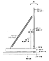
図2は、ステレオアダプタ9を示す平面図、図3は、第2ミラー23の図2のA方向矢視図である。
Details of the stereo adapter 9 will be described with reference to FIGS.
2 is a plan view showing the stereo adapter 9, and FIG. 3 is a view of the second mirror 23 as viewed in the direction of arrow A in FIG.
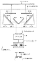
図2、図3に示すように、ステレオアダプタ9では、左目画像用の第1ミラー21−1、第2ミラー23−1、偏光フィルタ25−1、右目画像用の第1ミラー21−2、第2ミラー23−2、偏光フィルタ25−2等が筐体49内に設けられる。筐体49は、例えば中空の直方形状の箱である。 As shown in FIGS. 2 and 3, in the stereo adapter 9, the first mirror 21-1 for the left eye image, the second mirror 23-1, the polarization filter 25-1, the first mirror for the right eye image 21-2, A second mirror 23-2, a polarizing filter 25-2, and the like are provided in the housing 49. The housing 49 is, for example, a hollow rectangular box.
第1ミラー21−1、21−2は板状のミラーであり、筐体49の底面上に垂直に固定して設けられる。第1ミラー21−1、21−2は、プロジェクタ5からの画像の入射方向に対して、それぞれほぼ45度の角度をなしている。
また、第1ミラー21−1、21−2は、プロジェクタ5のプロジェクタレンズ7の中心線を中心として位置しており、プロジェクタ5から出射される画像を左右半分に分割する。即ち、第1ミラー21−1は、入射した画像の左半分である左目画像17を第2ミラー23−1の方向に反射し、第1ミラー21−2は、入射した画像の右半分である右目画像19を第2ミラー23−2の方向に反射する。
The first mirrors 21-1 and 21-2 are plate-like mirrors that are vertically fixed on the bottom surface of the housing 49. The first mirrors 21-1 and 21-2 make an angle of approximately 45 degrees with respect to the incident direction of the image from the
The first mirrors 21-1 and 21-2 are positioned around the center line of the projector lens 7 of the
水平ベース27−1、27−2は、筐体49の底面に軸29−1、29−2により軸支される。水平ベース27−1、27−2は、三角形状の板である。水平ベース27−1、27−2は、軸29−1、29−2を中心に回転可能である。
第2ミラー23−1、23−2は板状のミラーであり、水平ベース27−1、27−2に、ほぼ垂直に設けられる。水平ベース27−1、27−2が軸29−1、29−2を中心に回転すると、それに伴い、第2ミラー23−1、23−2の方向も変化する。
The horizontal bases 27-1 and 27-2 are pivotally supported on the bottom surface of the casing 49 by shafts 29-1 and 29-2. The horizontal bases 27-1 and 27-2 are triangular plates. The horizontal bases 27-1 and 27-2 can rotate around the axes 29-1 and 29-2.
The second mirrors 23-1 and 23-2 are plate-like mirrors and are provided substantially vertically on the horizontal bases 27-1 and 27-2. When the horizontal bases 27-1 and 27-2 rotate about the axes 29-1 and 29-2, the directions of the second mirrors 23-1 and 23-2 also change accordingly.
図3に示すように、第2ミラー23−1と水平ベース27−1は、第2ミラー可動用水平軸28により連結される。このため、第2ミラー23−1は第2ミラー可動用水平軸28の周りをB方向に回転可能である。第2ミラー23−1の後部には、水平ベース27−1に垂直ベース43−1が設置されている。垂直ベース43−1は、長方形状の板である。
また、第2ミラー23−1と水平ベース27−1の間には、スプリング45−1が設けられる。
As shown in FIG. 3, the second mirror 23-1 and the horizontal base 27-1 are connected by a second mirror moving horizontal shaft 28. Therefore, the second mirror 23-1 can rotate in the B direction around the second mirror moving horizontal axis 28. At the rear part of the second mirror 23-1, a vertical base 43-1 is installed on a horizontal base 27-1. The vertical base 43-1 is a rectangular plate.
A spring 45-1 is provided between the second mirror 23-1 and the horizontal base 27-1.
垂直ベース43−1には、第2ミラー23−1に先端が接触した状態となっている調整ネジ47−1が設けられる。
調整ネジ47−1を回して第2ミラー23−1に対してかかる力を変化させることにより、水平ベース27−1に対する第2ミラー23−1の角度が変化し、スクリーン11に投影される画像の上下方向の位置を調節することができる。
The vertical base 43-1 is provided with an adjusting screw 47-1 in which the tip is in contact with the second mirror 23-1.
By turning the adjusting screw 47-1 to change the force applied to the second mirror 23-1, the angle of the second mirror 23-1 with respect to the horizontal base 27-1 changes, and the image projected on the screen 11 The vertical position of can be adjusted.
連結軸31−1、31−2、リンケージ33−1、33−2、連結軸35、連結部37、操作バー39、ガイド41等は、水平ベース27−1、27−2を軸29−1、29−2中心に回転させる機構を構成する The connecting shafts 31-1, 31-2, the linkages 33-1, 33-2, the connecting shaft 35, the connecting portion 37, the operation bar 39, the guide 41, etc. are connected to the horizontal bases 27-1, 27-2 on the shaft 29-1. , 29-2 constitutes a mechanism to rotate around the center
ガイド41が、筐体49に対して固定される。
操作バー39は、ガイド41内を移動できるように設けられる。ガイド41は筒状で、操作バー39の外面とガイド41の内面にはネジが設けられ、操作バー39とガイド41が螺合する。あるいは、操作バー39は棒状にして、ガイド41内で前後に移動するようにしてもよい。
操作バー39の端部には、連結部37が設けられ、連結部37とリンケージ33−1、33−2が連結軸35によって軸着される。
操作バー39をガイド41内で前後に移動させることにより、リンケージ33−1、33−2間の角度が変化し、それに伴い水平ベース27−1、27−2が軸29−1、29−2を中心にして回転移動する。これにより、第2ミラー23−1、23−2の方向が変化する。
操作バー39により、水平ベース27−1、27−2を回転移動させて第2ミラー23−1、23−2の方向を調節することにより、スクリーン11に投影される画像の左右方向の位置を調節することができる。
The guide 41 is fixed with respect to the housing 49.
The operation bar 39 is provided so that it can move in the guide 41. The guide 41 is cylindrical, and screws are provided on the outer surface of the operation bar 39 and the inner surface of the guide 41, and the operation bar 39 and the guide 41 are screwed together. Alternatively, the operation bar 39 may be shaped like a rod and moved back and forth within the guide 41.
A connecting portion 37 is provided at the end of the operation bar 39, and the connecting portion 37 and the linkages 33-1 and 33-2 are attached by the connecting shaft 35.
By moving the operation bar 39 back and forth within the guide 41, the angle between the linkages 33-1 and 33-2 changes, and accordingly, the horizontal bases 27-1 and 27-2 are connected to the shafts 29-1 and 29-2. Rotate around the center. Thereby, the directions of the second mirrors 23-1 and 23-2 change.
By rotating and moving the horizontal bases 27-1 and 27-2 with the operation bar 39 and adjusting the directions of the second mirrors 23-1 and 23-2, the horizontal position of the image projected on the screen 11 can be adjusted. Can be adjusted.
偏光フィルタ25−1は左目画像用の偏光フィルタで、回折方向Aである。偏光フィルタ25−2は右目画像用偏光フィルタで、回折方向Bである。回折方向Aと回折方向Bは90度ずれており、偏光フィルタ25−1と偏光レンズ15−1、偏光フィルタ25−2と偏光レンズ15−2の回折方向はそれぞれ等しい。 The polarizing filter 25-1 is a polarizing filter for the left-eye image and is in the diffraction direction A. The polarizing filter 25-2 is a polarizing filter for the right eye image and is in the diffraction direction B. The diffraction direction A and the diffraction direction B are shifted by 90 degrees, and the diffraction directions of the polarizing filter 25-1 and the polarizing lens 15-1, and the polarizing filter 25-2 and the polarizing lens 15-2 are the same.
次に、立体視システム1を用いて立体画像をスクリーン11に投影するしくみについて説明する。
Next, a mechanism for projecting a stereoscopic image onto the screen 11 using the
パーソナルコンピュータ3は、一般的なアプリケーションを用いて、左目画像17、右目画像19を一画像化した画像、又は、映像をプロジェクタ5に出力する。
プロジェクタ5は、パーソナルコンピュータ3から入力した画像、映像を出射すると、第1ミラー21−1、21−2は左右半分ずつに分割し、それぞれ第2ミラー23−1、23−2の方向に反射する。
第1ミラー21−1、21−2により一画像化した画像、映像が左目画像17、右目画像19に分割されるように、プロジェクタ5、ステレオアダプタ9の設置位置を調整しておく。
The
When the
The installation positions of the
第2ミラー23−1、23−2は、第1ミラー21−1、21−2により左右半分ずつに分割された左目画像17、右目画像19をそれぞれ偏光フィルタ25−1、25−2の方向に反射する。
左目画像17は、回折方向Aの偏光フィルタ25−1を、右目画像19は、回折方向Bの偏光フィルタ25−2を通過し、スクリーン11上に投影される。
操作バー39、調整ネジ47−1、47−2により第2ミラー23−1、23−2の位置を調整することにより、スクリーン11上に投影される左目画像17、右目画像19がほぼ重なった状態となるようにする。これにより、視野闘争が起きるのを防ぐことができる。
ユーザは、偏光メガネ13をかけてスクリーン11を見ることにより、立体画像を見ることができる。
The second mirrors 23-1 and 23-2 convert the left-
The
By adjusting the positions of the second mirrors 23-1 and 23-2 with the operation bar 39 and the adjusting screws 47-1 and 47-2, the
The user can see a stereoscopic image by viewing the screen 11 while wearing the polarized glasses 13.
このように、本実施の形態によれば、1台のプロジェクタを用いて立体映像を投影することができる。また、動画立体視の場合も1台のコンピュータ、1台のプロジェクタにより実現することが可能となり、同期のためのシステムは不要となる。 Thus, according to the present embodiment, it is possible to project a stereoscopic image using a single projector. Also, in the case of moving image stereoscopic viewing, it can be realized by one computer and one projector, and a system for synchronization is not necessary.
また、ステレオアダプタ9では左目画像17、右目画像19の上下方向、左右方向の位置の調節が可能である。
更に、左目画像17、右目画像19の左右方向の位置を調節することにより、プロジェクタとスクリーン間のさまざまな投影距離に対応することが可能となる。
Further, the stereo adapter 9 can adjust the vertical and horizontal positions of the left-
Furthermore, by adjusting the positions of the
以上、添付図面を参照しながら本発明に係るステレオアダプタの好適な実施形態について説明したが、前述した実施の形態に限定されない。当業者であれば、特許請求の範囲に記載された技術的思想の範疇内において各種の変更例または修正例に想到し得ることは明らかであり、それらについても当然に本発明の技術的範囲に属するものと了解される。 The preferred embodiments of the stereo adapter according to the present invention have been described above with reference to the accompanying drawings, but are not limited to the above-described embodiments. It is obvious for those skilled in the art that various modifications or modifications can be conceived within the scope of the technical idea described in the claims, and these are naturally within the technical scope of the present invention. It is understood that it belongs.
1………立体視システム
3………パーソナルコンピュータ
5………プロジェクタ
7………プロジェクタレンズ
9………ステレオアダプタ
11………スクリーン
13………偏光メガネ
15………偏光レンズ
17………左目画像
19………右目画像
21………第1ミラー
23………第2ミラー
25………偏光フィルタ
27………水平ベース
28………第2ミラー可動用水平軸
29………軸
31………連結軸
33………リンケージ
35………連結軸
37………連結部
39………操作バー
41………ガイド
43………垂直ベース
45………スプリング
47………調整ネジ
49………筐体
1 ………
Claims (3)
分割された前記左目画像と前記右目画像を反射させる1対の第2のミラーと、
前記第2のミラーで反射された前記左目画像と前記右目画像を夫々透過させ、回折方向が90度異なる1対の偏光フィルタと、
前記1対の偏光フィルタを透過した前記左目画像及び前記右目画像が投影されるスクリーンと、
を具備することを特徴とするステレオアダプタ。 A pair of first mirrors for dividing a left-eye image and a right-eye image output from a single projector into a left-eye image and a right-eye image;
A pair of second mirrors for reflecting the divided left eye image and right eye image;
A pair of polarizing filters that transmit the left-eye image and the right-eye image reflected by the second mirror, respectively, and differ in diffraction direction by 90 degrees;
A screen on which the left-eye image and the right-eye image transmitted through the pair of polarizing filters are projected;
A stereo adapter comprising:
前記水平ベースは、鉛直軸の周りに回転可能であり、
前記水平ベースの位置を調整する第1の調整機能を備えることを特徴とする請求項1記載のステレオアダプタ。 The second mirror is provided on a horizontal base;
The horizontal base is rotatable about a vertical axis;
The stereo adapter according to claim 1, further comprising a first adjustment function for adjusting a position of the horizontal base.
前記第2のミラーの前記水平ベースに対する角度を調整する第2の調整機能を備えることを特徴とする請求項1記載のステレオアダプタ。 The second mirror is provided on a horizontal base;
The stereo adapter according to claim 1, further comprising a second adjustment function for adjusting an angle of the second mirror with respect to the horizontal base.
Priority Applications (1)
| Application Number | Priority Date | Filing Date | Title |
|---|---|---|---|
| JP2006158052A JP5076368B2 (en) | 2006-06-07 | 2006-06-07 | Stereo adapter |
Applications Claiming Priority (1)
| Application Number | Priority Date | Filing Date | Title |
|---|---|---|---|
| JP2006158052A JP5076368B2 (en) | 2006-06-07 | 2006-06-07 | Stereo adapter |
Publications (2)
| Publication Number | Publication Date |
|---|---|
| JP2007328067A true JP2007328067A (en) | 2007-12-20 |
| JP5076368B2 JP5076368B2 (en) | 2012-11-21 |
Family
ID=38928593
Family Applications (1)
| Application Number | Title | Priority Date | Filing Date |
|---|---|---|---|
| JP2006158052A Expired - Fee Related JP5076368B2 (en) | 2006-06-07 | 2006-06-07 | Stereo adapter |
Country Status (1)
| Country | Link |
|---|---|
| JP (1) | JP5076368B2 (en) |
Cited By (6)
| Publication number | Priority date | Publication date | Assignee | Title |
|---|---|---|---|---|
| WO2011003234A1 (en) * | 2009-07-08 | 2011-01-13 | 深圳市掌网立体时代视讯技术有限公司 | Optical stereo projection device, system and method |
| CN102207631A (en) * | 2010-03-29 | 2011-10-05 | 高春敏 | Popular single-machine stereo projection device |
| JP2012510644A (en) * | 2008-12-01 | 2012-05-10 | リアルディー インコーポレイテッド | Stereo projection system and method using spatial multiplexing on intermediate image plane |
| GB2485902A (en) * | 2010-11-29 | 2012-05-30 | Hae-Yong Choi | Stereoscopic projection adapter |
| WO2015032173A1 (en) * | 2013-09-05 | 2015-03-12 | 深圳市时代华影科技开发有限公司 | Stereographic projection device with low throw ratio and high light effect and stereographic projection system |
| KR20190063443A (en) * | 2017-11-29 | 2019-06-07 | 주식회사 레티널 | Optical device |
Citations (2)
| Publication number | Priority date | Publication date | Assignee | Title |
|---|---|---|---|---|
| JPH07311426A (en) * | 1995-05-12 | 1995-11-28 | Kokoku Bunko:Kk | Stereoscopic device for video recording machine |
| JP2005062607A (en) * | 2003-08-18 | 2005-03-10 | Sony Corp | 3-dimensional image projector and 3-dimensional image projection adapter |
-
2006
- 2006-06-07 JP JP2006158052A patent/JP5076368B2/en not_active Expired - Fee Related
Patent Citations (2)
| Publication number | Priority date | Publication date | Assignee | Title |
|---|---|---|---|---|
| JPH07311426A (en) * | 1995-05-12 | 1995-11-28 | Kokoku Bunko:Kk | Stereoscopic device for video recording machine |
| JP2005062607A (en) * | 2003-08-18 | 2005-03-10 | Sony Corp | 3-dimensional image projector and 3-dimensional image projection adapter |
Cited By (11)
| Publication number | Priority date | Publication date | Assignee | Title |
|---|---|---|---|---|
| JP2012510644A (en) * | 2008-12-01 | 2012-05-10 | リアルディー インコーポレイテッド | Stereo projection system and method using spatial multiplexing on intermediate image plane |
| EP2361401A4 (en) * | 2008-12-01 | 2015-07-29 | Reald Inc | Stereoscopic projection systems and methods for employing spatial multiplexing at an intermediate image plane |
| WO2011003234A1 (en) * | 2009-07-08 | 2011-01-13 | 深圳市掌网立体时代视讯技术有限公司 | Optical stereo projection device, system and method |
| CN102207631A (en) * | 2010-03-29 | 2011-10-05 | 高春敏 | Popular single-machine stereo projection device |
| GB2485902A (en) * | 2010-11-29 | 2012-05-30 | Hae-Yong Choi | Stereoscopic projection adapter |
| GB2485902B (en) * | 2010-11-29 | 2015-01-21 | Hae-Yong Choi | 3D image convertible projection optical system |
| WO2015032173A1 (en) * | 2013-09-05 | 2015-03-12 | 深圳市时代华影科技开发有限公司 | Stereographic projection device with low throw ratio and high light effect and stereographic projection system |
| US9638926B2 (en) | 2013-09-05 | 2017-05-02 | Shenzhen Time Waying Technology Co., Ltd. | Stereo projection apparatus and stereo projection system with low throw ratio and high light efficiency |
| EA030953B1 (en) * | 2013-09-05 | 2018-10-31 | Шэньчжэнь Тайм Вэинг Текнолоджи Ко., Лтд. | Stereo projection apparatus and stereo projection system with low throw ratio and high light efficiency |
| KR20190063443A (en) * | 2017-11-29 | 2019-06-07 | 주식회사 레티널 | Optical device |
| KR102314030B1 (en) * | 2017-11-29 | 2021-10-18 | 주식회사 레티널 | Optical device |
Also Published As
| Publication number | Publication date |
|---|---|
| JP5076368B2 (en) | 2012-11-21 |
Similar Documents
| Publication | Publication Date | Title |
|---|---|---|
| US10536687B2 (en) | Stereoscopic video imaging display system having a predetermined width of a viewing field angle | |
| JP4027898B2 (en) | Polarized transmission screen and stereoscopic image display apparatus using the polarized transmission screen | |
| EP2469336B1 (en) | Combining p and s rays for bright stereoscopic projection | |
| JP5076368B2 (en) | Stereo adapter | |
| JP5974547B2 (en) | Polarization control apparatus, projector system, polarization control method, and image control method | |
| JP2005215325A (en) | Stereoscopic image display device | |
| JP2012532341A (en) | Stereoscopic projection system using spatial multiplexing on the intermediate image plane | |
| RU2625815C2 (en) | Display device | |
| JP2006189837A (en) | Projection-type 3-d video display using single projector | |
| KR20120057916A (en) | 3d converting magnification of projection optical system | |
| JP2008191629A (en) | Stereoscopic projection adapter | |
| KR101162053B1 (en) | Stereoscopic image projector and optical converting apparatus for the stereoscopic image projector | |
| EP1906234B1 (en) | Adapter and three-dimensional image photograph apparatus having the same | |
| JP4609001B2 (en) | Pointer device | |
| RU2275754C2 (en) | Device for watching stereoscopic image represented by video display aid (versions) | |
| JP2005062607A (en) | 3-dimensional image projector and 3-dimensional image projection adapter | |
| JPH0954375A (en) | Liquid crystal projection device for stereoscopic vision | |
| JP2011008034A (en) | Stereo viewer device | |
| CN101790062B (en) | Stereoprojection device of single projector with single liquid crystal light valve | |
| KR101683788B1 (en) | Stereoscopic image projection system | |
| KR101236228B1 (en) | Stereoscopic image projector and optical converting apparatus for the stereoscopic image projector | |
| TWI476447B (en) | Stereoscopic projection display apparatus | |
| JP2013046081A (en) | Image capturing device and image generation method | |
| KR20170112136A (en) | Stereoscopic projector conversion system | |
| JP2005084669A (en) | Stereoscopic video projection device |
Legal Events
| Date | Code | Title | Description |
|---|---|---|---|
| A621 | Written request for application examination |
Free format text: JAPANESE INTERMEDIATE CODE: A621 Effective date: 20090522 |
|
| A977 | Report on retrieval |
Free format text: JAPANESE INTERMEDIATE CODE: A971007 Effective date: 20110623 |
|
| A131 | Notification of reasons for refusal |
Free format text: JAPANESE INTERMEDIATE CODE: A131 Effective date: 20110628 |
|
| A521 | Written amendment |
Free format text: JAPANESE INTERMEDIATE CODE: A523 Effective date: 20110829 |
|
| A131 | Notification of reasons for refusal |
Free format text: JAPANESE INTERMEDIATE CODE: A131 Effective date: 20120522 |
|
| A521 | Written amendment |
Free format text: JAPANESE INTERMEDIATE CODE: A523 Effective date: 20120705 |
|
| TRDD | Decision of grant or rejection written | ||
| A01 | Written decision to grant a patent or to grant a registration (utility model) |
Free format text: JAPANESE INTERMEDIATE CODE: A01 Effective date: 20120731 |
|
| A01 | Written decision to grant a patent or to grant a registration (utility model) |
Free format text: JAPANESE INTERMEDIATE CODE: A01 |
|
| A61 | First payment of annual fees (during grant procedure) |
Free format text: JAPANESE INTERMEDIATE CODE: A61 Effective date: 20120813 |
|
| FPAY | Renewal fee payment (event date is renewal date of database) |
Free format text: PAYMENT UNTIL: 20150907 Year of fee payment: 3 |
|
| R150 | Certificate of patent or registration of utility model |
Ref document number: 5076368 Country of ref document: JP Free format text: JAPANESE INTERMEDIATE CODE: R150 Free format text: JAPANESE INTERMEDIATE CODE: R150 |
|
| LAPS | Cancellation because of no payment of annual fees |