JP2007325636A - Chair type massage machine - Google Patents

Chair type massage machine Download PDF

Info

Publication number
JP2007325636A
JP2007325636A JP2006157131A JP2006157131A JP2007325636A JP 2007325636 A JP2007325636 A JP 2007325636A JP 2006157131 A JP2006157131 A JP 2006157131A JP 2006157131 A JP2006157131 A JP 2006157131A JP 2007325636 A JP2007325636 A JP 2007325636A
Authority
JP
Japan
Prior art keywords
massage
guide
seat
chair type
backrest
Prior art date
Legal status (The legal status is an assumption and is not a legal conclusion. Google has not performed a legal analysis and makes no representation as to the accuracy of the status listed.)
Pending
Application number
JP2006157131A
Other languages
Japanese (ja)
Inventor
Yoshifumi Fukuyama
美文 福山
Current Assignee (The listed assignees may be inaccurate. Google has not performed a legal analysis and makes no representation or warranty as to the accuracy of the list.)
Family Co Ltd
Original Assignee
Family Co Ltd
Priority date (The priority date is an assumption and is not a legal conclusion. Google has not performed a legal analysis and makes no representation as to the accuracy of the date listed.)
Filing date
Publication date
Application filed by Family Co Ltd filed Critical Family Co Ltd
Priority to JP2006157131A priority Critical patent/JP2007325636A/en
Publication of JP2007325636A publication Critical patent/JP2007325636A/en
Pending legal-status Critical Current

Links

Images

Abstract

<P>PROBLEM TO BE SOLVED: To provide a chair type massage machine which simultaneously gives a massage to two different sites in regions on both right and left sides of a body and in the direction of a body height. <P>SOLUTION: The chair type massage machine is equipped with a seat part 3 and a backrest part 4 and has a pair of right and left guide passages 6a, 6b placed inside the backrest part 4 by being divided into the right and left sides. A pair of right and left movable massaging units 8a, 8b are provided in the respective guide passages to correspond to the guide passages. Each of the massaging units 8a, 8b is loaded with a massaging device for giving a massage to a person to be treated. These massaging units 8a, 8b move independently along the respective guide passages by a moving mechanism. <P>COPYRIGHT: (C)2008,JPO&INPIT

Description

この発明は、椅子型マッサージ機に関する。   The present invention relates to a chair type massage machine.

背もたれ部にマッサージユニットが昇降自在に設けられている椅子型マッサージ機として従来知られているものに、例えば特許文献1、特許文献2に示しているものがある。これらはマッサージユニットによるマッサージ領域を左右方向に変更することができる。
つまり、特許文献1及び特許文献2に記載されている椅子型マッサージ機では、四個の施療子を一組として有している単一のマッサージユニットが背もたれ部内に設けられており、このマッサージユニットにおいて一組の施療子が背中に対して左の領域又は右の領域に移動することによって、マッサージ領域が左右のどちらかに変更される。
Conventionally known as a chair type massage machine in which a massage unit is provided on the backrest portion so as to be movable up and down, there are those shown in Patent Document 1 and Patent Document 2, for example. These can change the massage area by the massage unit in the left-right direction.
That is, in the chair type massage machine described in Patent Document 1 and Patent Document 2, a single massage unit having four treatment elements as a set is provided in the backrest portion. When the pair of treatment elements move to the left region or the right region with respect to the back, the massage region is changed to either the left or right region.

特開平9−262264号公報(図8参照)JP-A-9-262264 (see FIG. 8) 特開平10−337315号公報(図6参照)Japanese Patent Laid-Open No. 10-337315 (see FIG. 6)

しかし、上記従来の椅子型マッサージ機では、一組の施療子によるマッサージ領域が左右のどちらか一方に変更されるのみであるため、背中の左右片側領域の特定の一箇所だけしかマッサージすることができないという問題点を有している。
そこでこの発明は、身体の左右両側の領域でかつ長手方向(身長方向)で異なる二箇所の部位に対して同時にマッサージを行うことができる椅子型マッサージ機を提供することを目的とする。
However, in the above conventional chair type massage machine, the massage area by a set of treatment elements is only changed to either the left or right side, so only one specific area of the left and right side area of the back can be massaged. It has the problem that it cannot be done.
Therefore, an object of the present invention is to provide a chair-type massage machine that can simultaneously massage two regions that are different in the longitudinal direction (height direction) in the left and right regions of the body.

前記目的を達成するためのこの発明の椅子型マッサージ機は、座部と、この座部の後端部から立設された背もたれ部と、この背もたれ部の内部において左右方向に複数に振り分けて配置されかつ当該背もたれ部の長手方向に沿って延設された複数のガイド通路と、被施療者をマッサージするためのマッサージ具が搭載されかつ前記各ガイド通路に移動自在に設けられた複数のマッサージユニットと、これらのマッサージユニットを前記各ガイド通路に沿ってそれぞれ独立して移動させる移動機構とを備えている。   In order to achieve the above object, the chair type massage machine of the present invention has a seat portion, a backrest portion erected from the rear end portion of the seat portion, and a plurality of the chair type massage machines arranged in the left-right direction inside the backrest portion. A plurality of guide passages that are extended along the longitudinal direction of the backrest, and a plurality of massage units that are provided with massage devices for massaging the user and are movably provided in the respective guide passages And a moving mechanism for independently moving these massage units along the guide passages.

この構成によれば、背もたれ部の内部においてガイド通路が左右方向に複数に振り分けられて配置されており、これに対応してマッサージユニットが設けられている。そして、移動機構は、マッサージユニットのそれぞれを各ガイド通路に沿って独立して移動させることができる。このように各マッサージユニットを独立して移動させることで、身体の左右方向で複数の領域のそれぞれでかつ長手方向で異なる複数箇所の部位に対しても同時にマッサージすることができる。   According to this configuration, the guide passages are arranged in a plurality of left and right directions in the backrest portion, and a massage unit is provided correspondingly. The moving mechanism can move each of the massage units independently along each guide passage. Thus, by independently moving each massage unit, it is possible to simultaneously massage a plurality of regions that are different in the longitudinal direction in each of the plurality of regions in the left-right direction of the body.

また、前記ガイド通路は、前記背もたれ部の内部だけではなく前記座部の内部にも連続して延設されており、前記マッサージユニットは前記移動機構によって前記座部の領域にも移動可能となっているのが好ましい。
これによれば、マッサージユニットは座部の領域へ移動可能となり、座部においてマッサージを行うことができる。
Further, the guide passage extends continuously not only inside the backrest portion but also inside the seat portion, and the massage unit can be moved to the region of the seat portion by the moving mechanism. It is preferable.
According to this, the massage unit can be moved to the region of the seat, and massage can be performed in the seat.

また、前記座部の前端部に脚載せ部が設けられ、前記ガイド通路は、前記背もたれ部及び座部の内部だけでなく前記脚載せ部の内部にも連続して延設されており、前記マッサージユニットは前記移動機構によって前記脚載せ部の領域にも移動可能となっているのが好ましい。
これによれば、マッサージユニットは脚載せ部の領域へ移動可能となり、脚載せ部においてマッサージを行うことができる。
つまりこの構成によれば、背もたれ部、座部及び脚載せ部にわたる内部においてガイド通路が左右方向に複数に振り分けられて連続的に延設されることとなり、移動機構は、マッサージユニットのそれぞれを各ガイド通路に沿って独立して移動させ、背もたれ部、座部及び脚載せ部に択一的に対応させることができる。
Further, a leg placing portion is provided at a front end portion of the seat portion, and the guide passage extends continuously not only inside the backrest portion and the seat portion but also inside the leg placing portion, It is preferable that the massage unit can be moved also to the region of the leg rest by the moving mechanism.
According to this, the massage unit can move to the region of the leg rest, and massage can be performed on the leg rest.
In other words, according to this configuration, the guide passage is divided into a plurality of portions in the left-right direction and continuously extended inside the backrest portion, the seat portion, and the leg rest portion, and the moving mechanism moves each of the massage units. It can be moved independently along the guide path, and can selectively correspond to the backrest, the seat and the leg rest.

また、この発明の椅子型マッサージ機は、座部と、この座部の後端部から立設された背もたれ部と、この背もたれ部の内部において上下方向に複数に振り分けて配置されかつ当該背もたれ部の左右方向に沿って延設された複数のガイド通路と、被施療者をマッサージするためのマッサージ具が搭載されかつ前記ガイド通路に移動自在に設けられた複数のマッサージユニットと、このマッサージユニットを前記ガイド通路に沿ってそれぞれ独立して移動させる移動機構とを備えている。   Further, the chair type massage machine of the present invention includes a seat portion, a backrest portion erected from the rear end portion of the seat portion, and the backrest portion that is arranged in a plurality of parts in the vertical direction inside the backrest portion. A plurality of guide passages extending along the left-right direction, a plurality of massage units mounted with massage devices for massaging the user and movably provided in the guide passage, and the massage units And a moving mechanism for independently moving along the guide path.

この構成によれば、背もたれ部の内部においてガイド通路が上下方向に複数に振り分けられて配置されており、このガイド通路に移動自在とされてマッサージユニットが設けられている。そして、移動機構は、マッサージユニットをガイド通路に沿ってそれぞれ独立して移動させることができる。このようにマッサージユニットを独立して移動させることで、身体の上下複数の部位のそれぞれでかつ異なる左右方向の領域に対して同時にマッサージすることができる。   According to this configuration, the guide passages are arranged in a plurality of directions in the vertical direction inside the backrest, and the massage unit is provided so as to be movable in the guide passages. The moving mechanism can move the massage unit independently along the guide path. In this way, by independently moving the massage unit, it is possible to simultaneously massage each of the upper and lower parts of the body and different regions in the left-right direction.

また、一つのガイド通路にある前記マッサージユニットのマッサージ具を他のガイド通路に進入させて当該マッサージ具によるマッサージ領域を切り替えるための領域変更機構を、更に備えているのが好ましい。
この領域変更機構によれば、一つのガイド通路にあるマッサージユニットが有するマッサージ具を他のガイド通路に進入させて当該マッサージ具によるマッサージ領域を切り替えることができる。このため、被施療者の身体の左右方向の一領域において長手方向で異なる複数箇所の部位に対して同時にマッサージを行うことが可能となる。
Moreover, it is preferable to further include an area changing mechanism for switching the massage area by the massage tool by causing the massage tool of the massage unit in one guide path to enter another guide path.
According to this region changing mechanism, it is possible to switch the massage region by the massage device by causing the massage device of the massage unit in one guide passage to enter the other guide passage. For this reason, it becomes possible to simultaneously massage a plurality of parts that are different in the longitudinal direction in one region in the left-right direction of the body of the user.

また、前記各椅子型マッサージ機において、前記マッサージユニットは、複数個の施療子と、これら施療子を互いに接近又は離反させる駆動機構と、これら施療子が接近又は離反する方向を変更させる角度調整機構とを有しているのが好ましい。
この構成によれば、複数の施療子を接近又は離反させることで、挟み揉みによるマッサージが可能となる。そして、角度調整機構により、複数の施療子によって行われる挟み揉みの方向を上下左右に変更できる。
In each of the chair type massage machines, the massage unit includes a plurality of treatment elements, a drive mechanism that causes the treatment elements to approach or separate from each other, and an angle adjustment mechanism that changes a direction in which the treatment elements approach or separate. It is preferable to have.
According to this structure, the massage by pinching is attained by making a some treatment element approach or separate. Then, the direction of the pinching performed by the plurality of treatment elements can be changed vertically and horizontally by the angle adjusting mechanism.

また、前記マッサージユニットは、前記ガイド通路に沿って移動するためのモータを搭載しているのが好ましい。
これにより、マッサージユニットはガイド通路を自走することができる。
Moreover, it is preferable that the massage unit is equipped with a motor for moving along the guide path.
Thereby, the massage unit can be self-propelled in the guide passage.

本発明の椅子型マッサージ機によれば、マッサージユニットをそれぞれ独立して移動させることができ、身体の左右方向で複数の領域のそれぞれでかつ長手方向で異なる複数箇所の部位に対して同時にマッサージを行うことができる。   According to the chair type massage machine of the present invention, the massage units can be moved independently, and massage can be performed simultaneously on each of a plurality of regions in the left and right direction of the body and on a plurality of different parts in the longitudinal direction. It can be carried out.

以下、この発明の実施の形態について図面を参照しながら説明する。
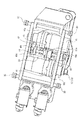
図1はこの発明の椅子型マッサージ機の実施の一形態を示す後方からの斜視図であり、図2はその側面図である。また、図3はこの椅子型マッサージ機の背面図であり、図4はその底面図である。
この椅子型マッサージ機は、上面が被施療者を着座させる座面3aとされた座部3と、この座部3の後端部から立設された背もたれ部4と、座部3の前端部に設けられた脚載せ部5と、座部3の左右両側に設けられて座部3と背もたれ部4と脚載せ部5とを床面に対して支持している左右一対の脚部16とを備えている。なお、本発明において、座部3に着座した被施療者の左手側を「左」とし、右手側を「右」としている。
Embodiments of the present invention will be described below with reference to the drawings.
FIG. 1 is a rear perspective view showing an embodiment of a chair type massage machine of the present invention, and FIG. 2 is a side view thereof. FIG. 3 is a rear view of the chair type massage machine, and FIG. 4 is a bottom view thereof.
This chair type massage machine includes a seat portion 3 whose upper surface is a seat surface 3a on which a user is seated, a backrest portion 4 erected from the rear end portion of the seat portion 3, and a front end portion of the seat portion 3. And a pair of left and right legs 16 provided on the left and right sides of the seat 3 and supporting the seat 3, the backrest 4 and the leg rest 5 with respect to the floor surface. It has. In the present invention, the left hand side of the user seated on the seat 3 is “left” and the right hand side is “right”.

背もたれ部4は被施療者の上半身、つまり腰部から肩部、さらには頭部までを支持することができ、座部3は被施療者の臀部から大腿部を支持することができる。そして、脚載せ部5は被施療者の膝から脚先部分を支持することができる。脚載せ部5は特に被施療者の左右各脚のふくらはぎの背面側に当接して脚を支持することができる。   The backrest part 4 can support the upper body of the user, that is, the waist part to the shoulder part, and further to the head part, and the seat part 3 can support the thigh part from the buttocks part of the user. And the leg mounting part 5 can support a leg tip part from a knee of a user. In particular, the leg rest 5 can support the leg by abutting against the back side of the calf of the left and right legs of the user.

この椅子型マッサージ機は、被施療者(患部)に対してマッサージするためのマッサージ具が搭載されているマッサージユニット8と、このマッサージユニット8を移動させるために設けられたガイド通路6とを備えている。
具体的には、椅子型マッサージ機は、ガイド通路6として左右一対のガイド通路6a,6bを備えており、これに対応して、左右一対のマッサージユニット8a,8bを備えている。一対のガイド通路6a,6bは、背もたれ部4の内部に左側と右側に振り分けて配置されており、ガイド通路6a,6bのそれぞれは、背もたれ部4の長手方向(上下方向)に沿って延設されている。そして、マッサージユニット8a,8bのそれぞれは、ガイド通路6a,6bのそれぞれにガイドされて移動自在とされている。
This chair type massage machine includes a massage unit 8 on which a massage tool for massaging a user (affected part) is mounted, and a guide passage 6 provided for moving the massage unit 8. ing.
Specifically, the chair type massage machine includes a pair of left and right guide passages 6a and 6b as the guide passage 6, and a pair of left and right massage units 8a and 8b corresponding thereto. The pair of guide passages 6a and 6b are arranged inside the backrest portion 4 so as to be divided into the left side and the right side, and each of the guide passages 6a and 6b extends along the longitudinal direction (vertical direction) of the backrest portion 4. Has been. The massage units 8a and 8b are guided by the guide passages 6a and 6b, respectively, and are movable.

また、図1〜図4の椅子型マッサージ機において、左右一対のガイド通路6a,6bは、背もたれ部4の内部だけではなく座部3の内部にも連続して延設されている。これにより、マッサージユニット8a,8bは座部3の領域にも移動可能となっている。さらに、このガイド通路6a,6bは、背もたれ部4及び座部3の内部だけでなく脚載せ部5の内部にも連続して延設されている。これにより、マッサージユニット8a,8bは脚載せ部5の領域にも移動可能となっている。
そして、椅子型マッサージ機が備えている移動機構9(図10参照)が、これらのマッサージユニット8a,8bを各ガイド通路6a,6bに沿ってそれぞれ独立して移動させることができる。
1 to 4, the pair of left and right guide passages 6 a and 6 b are continuously extended not only inside the backrest part 4 but also inside the seat part 3. Thereby, massage unit 8a, 8b can also move to the area | region of the seat part 3. FIG. Further, the guide passages 6 a and 6 b are continuously extended not only inside the backrest part 4 and the seat part 3 but also inside the leg rest part 5. Thereby, massage unit 8a, 8b can also move to the area | region of the leg mounting part 5. FIG.
And the movement mechanism 9 (refer FIG. 10) with which the chair type massage machine is provided can move these massage units 8a and 8b independently along the guide passages 6a and 6b.

ガイド通路6a,6bについて具体的に説明する。ガイド通路6a,6bは、背もたれ部4の上部から座部3を経て脚載せ部5の下部まで連続しており、相互が平行とされて設けられている。これにより、マッサージユニット8a,8bのそれぞれを前記上部から前記下部まで連続的に移動させることができる。
ガイド通路6a,6bのそれぞれは、図2において、背もたれ部4の内部においてその長手方向にまっすぐに延伸している第一ガイド部51と、座部3の内部においてその長手方向にまっすぐ延伸している第二ガイド部52と、脚載せ部5の内部においてその長手方向にまっすぐ延伸している第三ガイド部53とを有しており、さらに、第一ガイド部51と第二ガイド部52との間を連結している湾曲状の第一連結ガイド部54と、第二ガイド部52と第三ガイド部53との間を連結している湾曲状(屈曲状)の第二連結ガイド部55とを有している。つまり、ガイド通路6a,6bは、背もたれ部4から脚載せ部5まで連続して一続きとされている。
The guide passages 6a and 6b will be specifically described. The guide passages 6a and 6b are continuous from the upper part of the backrest part 4 through the seat part 3 to the lower part of the leg rest part 5, and are provided in parallel with each other. Thereby, each of massage unit 8a, 8b can be continuously moved from the said upper part to the said lower part.
In FIG. 2, each of the guide passages 6 a and 6 b extends straight in the longitudinal direction in the longitudinal direction inside the seat portion 3 and the first guide portion 51 that extends straight in the longitudinal direction inside the backrest portion 4. The second guide portion 52 and the third guide portion 53 extending straight in the longitudinal direction inside the leg rest portion 5, and the first guide portion 51 and the second guide portion 52, A curved first connection guide portion 54 that connects the two, and a curved (bent) second connection guide portion 55 that connects the second guide portion 52 and the third guide portion 53. And have. In other words, the guide passages 6 a and 6 b are continuous from the backrest part 4 to the leg rest part 5.

そして被施療者に対してマッサージを施すマッサージ具はマッサージユニット8に搭載されている。図5はこのマッサージ具を搭載しているマッサージユニットの実施の一形態を示す斜視図である。なお、一対のマッサージユニット8a,8bの一方に一つのマッサージ具7が搭載され、他方に別の一つのマッサージ具7が搭載されている。そして、両マッサージ具7は同一のものとされている。   A massage tool for performing massage on the user is mounted on the massage unit 8. FIG. 5 is a perspective view showing an embodiment of a massage unit equipped with this massage device. One massage tool 7 is mounted on one of the pair of massage units 8a and 8b, and another massage tool 7 is mounted on the other. And both the massage tools 7 are made into the same thing.

図5において、マッサージユニット8はフレーム28を有しており、このフレーム28に前記マッサージ具7が搭載されている。フレーム28のほぼ矩形状の本体部分28bの四隅にはそれぞれローラ30が回転自在に取り付けられており、これらローラ30が回転することで前記ガイド通路6a,6bに沿ってマッサージユニット8は移動することができる。つまり、ガイド通路6a,6bのそれぞれは左右に一対のガイド溝57a,57b(図1参照)を有しており、マッサージユニット8の左右のローラ30がこれらガイド溝57a,57bを走行する。ガイド溝57a,57bは断面コ字形とされており、背もたれ部4から脚載せ部5まで連続して一続きとされている。   In FIG. 5, the massage unit 8 has a frame 28, and the massage tool 7 is mounted on the frame 28. Rollers 30 are rotatably attached to the four corners of the substantially rectangular main body portion 28b of the frame 28, and the massage unit 8 moves along the guide passages 6a and 6b as these rollers 30 rotate. Can do. In other words, each of the guide passages 6a and 6b has a pair of guide grooves 57a and 57b (see FIG. 1) on the left and right, and the left and right rollers 30 of the massage unit 8 travel through the guide grooves 57a and 57b. The guide grooves 57a and 57b have a U-shaped cross section, and are continuous from the backrest 4 to the leg rest 5.

マッサージユニット8に搭載されているマッサージ具7は複数の施療子1a,1b,2を備えている。そして、これら施療子1a,1b,2が取り付けられている側が被施療者側となるようにして、マッサージユニット8はガイド通路6にガイドされた状態で椅子本体に取り付けられている。
図1〜図4において、座部3、背もたれ部4及び脚載せ部5のそれぞれにおいて、被施療者側に開口部56が形成されている。開口部56は背もたれ部4の背もたれ面4aから座部3の座面3aを経て脚載せ部5の脚載せ面5aにわたって連続している一つの長穴として形成されている。また、開口部56は左右一対のガイド通路6a,6bの両者にわたって左右幅方向に開口している。
そして、この開口部56にマッサージ具7の施療子1a,1b,2が対応し、当該施療子1a,1b,2が動作することによって、被施療者に対してマッサージを施すことができる。なお、この開口部56は図示しない布製などの弾性のあるカバー部材によって覆われている。
The massage tool 7 mounted on the massage unit 8 includes a plurality of treatment elements 1a, 1b, and 2. And the massage unit 8 is attached to the chair main body in the state guided by the guide channel | path 6 so that the side by which these treatment elements 1a, 1b, 2 are attached becomes a user's side.
1 to 4, an opening 56 is formed on the user side in each of the seat portion 3, the backrest portion 4, and the leg rest portion 5. The opening 56 is formed as one elongated hole that extends from the backrest surface 4a of the backrest portion 4 through the seat surface 3a of the seat portion 3 to the leg rest surface 5a of the leg rest portion 5. Moreover, the opening part 56 is opened in the left-right width direction over both the left-right paired guide channel | paths 6a and 6b.
And the treatment element 1a, 1b, 2 of the massage tool 7 respond | corresponds to this opening part 56, and the said treatment element 1a, 1b, 2 operate | moves, and it can massage to a user. The opening 56 is covered with an elastic cover member such as cloth (not shown).

マッサージユニット8a,8bをガイド通路6a,6bに沿って移動させる移動機構9(図10参照)について具体的に説明する。移動機構9は図示しないがモータなどを有する駆動部を備えており、椅子型マッサージ機が備えている制御手段10からの動作信号に基づいて動作することができる。
具体的な構成は、図示しないが例えば、モータを含む移動機構9をマッサージユニット8(図5参照)のそれぞれに搭載させ、各マッサージユニット8が自走する構成とすることができる。つまり、図5において、四個の前記ローラ30の少なくとも一つは図示しない走行用のモータによって回転駆動するように構成されており、このローラ30がガイド通路6a,6bの前記ガイド溝57a,57bを走行駆動することによって、マッサージユニット8は移動することができる。この場合において、ローラ30の外周面に歯が形成されてピニオンを構成している。また、ガイド溝57a,57bにこのピニオンが噛み合うラック部が形成されている。そして、マッサージユニット8に搭載したモータの回転を減速機構を介して前記ピニオンに伝達し、ピニオンを回転させることでマッサージユニット8をガイド通路6に沿って移動させている。
The moving mechanism 9 (see FIG. 10) for moving the massage units 8a and 8b along the guide passages 6a and 6b will be specifically described. Although not shown, the moving mechanism 9 includes a drive unit having a motor or the like, and can operate based on an operation signal from the control means 10 included in the chair type massage machine.
Although a specific configuration is not illustrated, for example, a moving mechanism 9 including a motor can be mounted on each massage unit 8 (see FIG. 5), and each massage unit 8 can be self-run. That is, in FIG. 5, at least one of the four rollers 30 is configured to be rotationally driven by a traveling motor (not shown), and this roller 30 is guided by the guide grooves 57a and 57b of the guide passages 6a and 6b. The massage unit 8 can be moved by driving. In this case, teeth are formed on the outer peripheral surface of the roller 30 to constitute a pinion. In addition, a rack portion that engages with the pinion is formed in the guide grooves 57a and 57b. Then, the rotation of the motor mounted on the massage unit 8 is transmitted to the pinion via a speed reduction mechanism, and the massage unit 8 is moved along the guide passage 6 by rotating the pinion.

以上の実施の形態によれば、この椅子型マッサージ機は、図1において、背もたれ部4、座部3及び脚載せ部5の内部に左側と右側に振り分けて配置されかつこれらの各部にわたって連続的に延設された左右一対のガイド通路6a,6bと、被施療者をマッサージするためのマッサージ具7が搭載されかつ各ガイド通路6a,6bに移動自在に設けられた左右一対のマッサージユニット8a,8bと、これらのマッサージユニット8a,8bを各ガイド通路6a,6cに沿ってそれぞれ独立して移動させる移動機構9(図10参照)とを備えている。これによれば、移動機構9が各マッサージユニット8a,8bを独立して移動させることができ、身体の左右両側の領域のそれぞれでかつ長手方向で異なる二箇所の部位に対しても同時にマッサージすることが可能となる。   According to the above embodiment, this chair type massage machine is arranged in the backrest part 4, the seat part 3 and the leg rest part 5 in FIG. A pair of left and right guide passages 6a and 6b extending to the left and right and a pair of left and right massage units 8a mounted with a massage device 7 for massaging the user and movably provided in the guide passages 6a and 6b. 8b and a moving mechanism 9 (see FIG. 10) that moves these massage units 8a and 8b independently along the guide passages 6a and 6c. According to this, the movement mechanism 9 can move each massage unit 8a, 8b independently, and it massages simultaneously also to two site | parts which are different in each of the area | region of the right-and-left both sides of a body, and a longitudinal direction. It becomes possible.

例えば、図示しないが、左右一対のマッサージユニット8a,8bのうちの左側の一方を、背もたれ部4の領域に存在させている状態で、右側の他方を座部3の領域に存在させることができる。この場合、椅子型マッサージ機は被施療者に対して、一方のマッサージユニット8aが背中の左側部を、他方のマッサージユニット8bが臀部から大腿部の右側部をマッサージすることができる。
または、一対のマッサージユニット8a,8bのうちの左側の一方を、背もたれ部4又は座部3の領域に存在させている状態で、右側の他方を脚載せ部5の領域に存在させることができる。この場合、椅子型マッサージ機は被施療者に対して、一方のマッサージユニット8aが背中の左側部、又は、臀部から大腿部の左側部を、そして、他方のマッサージユニット8bが右脚の例えばふくらはぎをマッサージすることができる。
For example, although not shown, the left side of the pair of left and right massage units 8a and 8b can be present in the region of the backrest portion 4 and the other of the right side can be present in the region of the seat portion 3. . In this case, the chair-type massage machine can massage the user with one massage unit 8a on the left side of the back and the other massage unit 8b on the right side of the thigh from the buttocks.
Alternatively, one of the left side of the pair of massage units 8a and 8b can be present in the region of the backrest 4 or the seat 3 and the other of the right side can be present in the region of the leg rest 5. . In this case, for example, the chair type massage machine has a massage unit 8a for the left side of the back or the left side of the thigh from the buttocks and the other massage unit 8b for the right leg. You can massage your calf.

つまり本発明の構成によれば、移動機構9は、左右一対のマッサージユニット8a,8bのそれぞれを各ガイド通路6a,6bに沿って独立して移動させ、背もたれ部4、座部3及び脚載せ部5に択一的に対応させることができる。このようにマッサージユニット8a,8bのそれぞれを独立して移動させることで、身体の左右両側の領域のそれぞれでかつ長手方向で異なる二箇所の部位に対しても同時にマッサージを行うことができる。   That is, according to the configuration of the present invention, the moving mechanism 9 moves the pair of left and right massage units 8a and 8b independently along the guide passages 6a and 6b, and the backrest part 4, the seat part 3 and the leg rest. It can be made to correspond to the part 5 alternatively. In this manner, by independently moving the massage units 8a and 8b, it is possible to perform massage simultaneously on two portions that are different in the longitudinal direction in each of the left and right regions of the body.

また、本発明の椅子型マッサージ機は、左右一対のマッサージユニット8a,8bのうちのいずれか一方のマッサージユニットのマッサージ具7を、他方のガイド通路6に進入させて当該マッサージ具7によるマッサージ領域を切り替えるための領域変更機構を更に備えている。図11は、この領域変更機構の機能を説明するための概略図である。
図11に示しているように、領域変更機構は、一方のガイド通路6a側に存在していた一方のマッサージユニット8aを、移動機構9(図10参照)の働きにより他方のガイド通路6b側へ移動させることによって、一方側にあった前記マッサージユニット8aのマッサージ具7を、他方側のガイド通路6bへ進入させる構造とされている。これによりマッサージユニット8aのマッサージ領域を一方側から他方側へ切り替えている。
Moreover, the chair type massage machine of this invention makes the massage tool 7 of any one of left-right paired massage unit 8a, 8b approach the other guide channel | path 6, and the massage area | region by the said massage tool 7 is used. An area changing mechanism for switching between them is further provided. FIG. 11 is a schematic diagram for explaining the function of the area changing mechanism.
As shown in FIG. 11, the region changing mechanism moves one massage unit 8 a existing on one guide passage 6 a side to the other guide passage 6 b side by the action of the moving mechanism 9 (see FIG. 10). By making it move, it is set as the structure which makes the massage tool 7 of the said massage unit 8a which existed in one side approach into the guide channel | path 6b of the other side. Thereby, the massage region of the massage unit 8a is switched from one side to the other side.

この領域変更機構を構成するために、背もたれ部4の上部及び下部のそれぞれ、又は、背もたれ部4の上部と脚載せ部5の下部のそれぞれにおいて、左右のガイド通路6a,6bは湾曲部を介して繋がっており、マッサージユニット8a,8bは、両ガイド通路6a,6b間を相互移動することができる。これにより、図11のように、左側のガイド通路6aに存在していた一方のマッサージユニット8aを右側のガイド通路6bの上部に位置させ、右側のガイド通路6bの下部に他方のマッサージユニット8bを位置させることができる。また、反対に、右側のガイド通路6bに存在していたマッサージユニット8bを左側のガイド通路6aに位置させることもできる。   In order to configure this region changing mechanism, the left and right guide passages 6a and 6b are respectively connected to the upper and lower parts of the backrest part 4 or the upper part of the backrest part 4 and the lower part of the leg rest part 5 via the curved parts. The massage units 8a and 8b can move between the guide passages 6a and 6b. As a result, as shown in FIG. 11, the one massage unit 8a existing in the left guide passage 6a is positioned at the upper portion of the right guide passage 6b, and the other massage unit 8b is placed at the lower portion of the right guide passage 6b. Can be positioned. On the contrary, the massage unit 8b existing in the right guide passage 6b can be positioned in the left guide passage 6a.

このように領域変更機構によれば、被施療者の背中の左右片側領域の一方において長手方向で異なる二箇所の部位に対して同時にマッサージを行うことができる。つまり、図11では被施療者の背中の右側領域の上下二箇所の部位に対して同時にマッサージを行うことができる。
また、左右のガイド通路6a,6bのそれぞれは、背もたれ部4から脚載せ部5まで連続しているため、被施療者の上半身から脚の範囲のうちの左右片側領域の一方側において長手方向で異なる二箇所の部位(例えば背中の右側部と右ふくらはぎ部)に両マッサージユニット8a,8bを位置させ、当該二箇所の部位に対して同時にマッサージを行うことができる。
As described above, according to the region changing mechanism, it is possible to simultaneously perform massage on two portions different in the longitudinal direction in one of the left and right one side regions of the back of the user. That is, in FIG. 11, massage can be performed simultaneously on the upper and lower two portions of the right region of the back of the user.
In addition, since each of the left and right guide passages 6a and 6b is continuous from the backrest 4 to the leg rest 5, a longitudinal direction is provided on one side of the left and right one side region in the range of the user's upper body to the leg. Both massage units 8a and 8b can be positioned at two different sites (for example, the right side of the back and the right calf), and the two sites can be massaged simultaneously.

図13は、本発明の椅子型マッサージ機の他の実施の形態を示す背面図である。図3で示した前記実施の形態では二列のガイド通路6a,6bを有している構成とされているが、図13に示している実施の形態では、三列のガイド通路6a,6b,6cを有している構成とされている。そして、ガイド通路6a,6b,6cのそれぞれにマッサージユニット8a,8b,8cが設けられている。その他の構成については同様とされている。なお、図13の実施の形態においても、前記と同様の領域変更機構を設けることができ、これによって、一つのガイド通路にあるマッサージユニットのマッサージ具を、他のガイド通路に進入させて当該マッサージ具によるマッサージ領域を切り替えることができる。   FIG. 13: is a rear view which shows other embodiment of the chair type massage machine of this invention. In the embodiment shown in FIG. 3, the two rows of guide passages 6a and 6b are configured. However, in the embodiment shown in FIG. 13, three rows of guide passages 6a, 6b, 6c. And massage unit 8a, 8b, 8c is provided in guide passage 6a, 6b, 6c, respectively. Other configurations are the same. In the embodiment of FIG. 13 as well, an area changing mechanism similar to that described above can be provided, so that the massage tool of the massage unit in one guide passage can enter the other guide passage and the massage is performed. The massage area with the device can be switched.

また、本発明において、ガイド通路の数は以上の実施の形態に制限されるものではなく、ガイド通路は、背もたれ部4の内部において左右方向に複数に振り分けて配置され、かつ、当該背もたれ部の長手方向に沿って延設されたものとすることができる。さらには、そのガイド通路は、背もたれ部のみならず、座部の内部や脚載せ部の内部にも連続して延設されており、マッサージユニットは移動機構によって座部の領域や、脚載せ部の領域にも独立して移動可能とすることができる。   In the present invention, the number of the guide passages is not limited to the above embodiment, and the guide passages are arranged in a plurality of left and right directions inside the backrest portion 4 and the backrest portions are arranged. It can be extended along the longitudinal direction. Furthermore, the guide passage extends continuously not only in the backrest portion but also in the seat portion and in the leg rest portion, and the massage unit is moved by the moving mechanism so that the area of the seat portion and the leg rest portion are extended. It is possible to move independently to the area.

図14は、本発明の椅子型マッサージ機の別の実施の形態を示す背面図である。
この椅子型マッサージ機は、図3で示した実施の形態と同様に、座部3と、この座部3の後端部から立設された背もたれ部4とを備えている。しかし、この椅子型マッサージ機では、背もたれ部4に設けられているガイド通路は、当該背もたれ部4の内部において上下方向に複数に振り分けられて複数配置され(6a,6b,6c…)、かつ、当該背もたれ部4の左右方向に沿って延設されている構造である。
そして、この椅子型マッサージ機はマッサージユニット8a,8bを備えており、このマッサージユニット8a,8bのそれぞれには、前記実施形態と同様の被施療者をマッサージするためのマッサージ具が搭載されており、かつマッサージユニット8a,8bのそれぞれはガイド通路6a,6b,6c…に移動自在に設けられている。そして、前記実施形態と同様に、椅子型マッサージ機が備えている移動機構によって、このマッサージユニット8a,8bをガイド通路6a,6b,6c…に沿って移動させることができる。
FIG. 14 is a rear view showing another embodiment of the chair type massage machine of the present invention.
Similar to the embodiment shown in FIG. 3, the chair-type massage machine includes a seat portion 3 and a backrest portion 4 erected from the rear end portion of the seat portion 3. However, in this chair-type massage machine, a plurality of guide passages provided in the backrest part 4 are arranged in the vertical direction inside the backrest part 4 and are arranged in a plurality (6a, 6b, 6c ...), and This is a structure extending along the left-right direction of the backrest 4.
And this chair type massage machine is equipped with massage unit 8a, 8b, The massage tool for massaging the treated person similar to the said embodiment is mounted in each of this massage unit 8a, 8b. The massage units 8a, 8b are movably provided in the guide passages 6a, 6b, 6c. And like the said embodiment, this massage unit 8a, 8b can be moved along guide channel | path 6a, 6b, 6c ... with the moving mechanism with which the chair type massage machine is equipped.

この図14の実施の形態においても、前記の領域変更機構を設けることができ、これによって、一つのガイド通路、例えばガイド通路6aにあるマッサージユニット8aのマッサージ具を、他のガイド通路(ガイド通路6b)に進入させて当該マッサージ具によるマッサージ領域を切り替えることができる。これを具体的に説明すると、これら複数のガイド通路6a,6b,6c…は湾曲部を介して繋がっており、複数のガイド通路6a,6b,6c…によって一条の連続した蛇行状通路が構成されている。そして、マッサージユニット8a(8b)は、この蛇行状通路に沿って移動(自走)することができ、蛇行状通路のうちの一つのガイド通路からその隣のガイド通路へ移動することができる。そして、所望の位置に停止して被施療者に対してマッサージ動作を行わせることができる。   In the embodiment shown in FIG. 14 as well, the region changing mechanism can be provided so that the massage tool of the massage unit 8a in one guide passage, for example, the guide passage 6a can be transferred to another guide passage (guide passage). 6b) can be entered to switch the massage area by the massage tool. Specifically, the plurality of guide passages 6a, 6b, 6c... Are connected via a curved portion, and a plurality of guide passages 6a, 6b, 6c. ing. And the massage unit 8a (8b) can move (self-propelled) along this serpentine path, and can move from one guide path of the serpentine paths to the adjacent guide path. And it can stop at a desired position and can make a user perform a massage operation.

図1から図4に示した実施の形態において、左右一対のマッサージユニット8a,8bにそれぞれ搭載されているマッサージ具7について説明する。この実施の形態では、左右の両者は同じマッサージ具7とされているため、一方についてのみ説明する。図6はマッサージ具の要部を示す斜視図であり、図7はマッサージ具の断面側面図である。なお、図13及び図14に示した椅子型マッサージ機に設けられるマッサージユニットについても、同様の構成とすることができる。
このマッサージ具7は被施療者をマッサージするための施療子(揉み玉)を備えている。本発明の施療子は、複数個の第一施療子と、この第一施療子より少ない個数の第二施療子とからなっている。なお、図に示している施療子は、二個の第一施療子1a,1bと、一個の第二施療子2とからなる。そして、本発明のマッサージ具7は、これら第一施療子1a,1b及び第二施療子2を互いに接近又は離反させる揉み駆動機構11を備えている。
In the embodiment shown in FIGS. 1 to 4, the massage device 7 mounted on each of the pair of left and right massage units 8 a and 8 b will be described. In this embodiment, since both the left and right are the same massage tool 7, only one will be described. FIG. 6 is a perspective view showing a main part of the massage device, and FIG. 7 is a sectional side view of the massage device. In addition, it can be set as the same structure also about the massage unit provided in the chair type massage machine shown in FIG.13 and FIG.14.
This massage tool 7 is provided with a treatment element (massage ball) for massaging the user. The treatment element of the present invention includes a plurality of first treatment elements and a smaller number of second treatment elements than the first treatment elements. In addition, the treatment element shown to the figure consists of the two 1st treatment elements 1a and 1b and the one 2nd treatment element 2. FIG. And the massage tool 7 of this invention is provided with the stagnation drive mechanism 11 which makes these 1st treatment elements 1a and 1b and the 2nd treatment element 2 approach or separate from each other.

二個の第一施療子1a,1bは隣り合わせで並んで配設されており、第二施療子2はこれら第一施療子1a,1bと対向して設けられている。これにより、揉み駆動機構11が第一施療子1a,1b及び第二施療子2を互いに接近又は離反させる動作を行わせることによって、第一施療子1a,1bは人の手の親指以外の指(人差し指と中指)に見立てられるとともに、第二施療子2は親指に見立てられ、これら三個の施療子によって挟み揉みによるマッサージが可能となる。つまり人の手によるマッサージにより近似した好適なマッサージを行うことができる。また、第一施療子1a,1bと第二施療子2とは異なる大きさの略球形とされており、第一施療子1a,1bが第二施療子2よりも大きくされている。
また、軸心C1の方向に沿って施療子を見た場合において、第一施療子1aの動作方向と、第一施療子1bの動作方向とは、平行とすることもできる。
The two first treatment elements 1a and 1b are arranged side by side, and the second treatment element 2 is provided to face the first treatment elements 1a and 1b. As a result, the stagnation drive mechanism 11 causes the first treatment elements 1a, 1b and the second treatment element 2 to move toward or away from each other, so that the first treatment elements 1a, 1b (The index finger and the middle finger) and the second treatment element 2 can be regarded as a thumb, and these three treatment elements can be massaged by pinching. In other words, a suitable massage approximated by a massage by a human hand can be performed. In addition, the first treatment element 1a, 1b and the second treatment element 2 are substantially spherical in size, and the first treatment element 1a, 1b is larger than the second treatment element 2.
Further, when the treatment element is viewed along the direction of the axis C1, the operation direction of the first treatment element 1a and the operation direction of the first treatment element 1b may be parallel.

揉み駆動機構11について具体的に説明する。
図7において、揉み駆動機構11は、平らなプレート状の本体部分29aを有しているベース部材29を備えており、この本体部分29aから複数の突出部材20が突出して設けられている。図示している揉み駆動機構11では、前記施療子の数に対応して三本の突出部材20を備えている(図6参照)。各突出部材20はまっすぐな円柱部材とされており、基端部側がベース部材29に取り付けられている。
そして、この突出部材20の先端部側に前記第一施療子1a,1b及び第二施療子2の内の一つがそれぞれ揺動自在として枢着されている。これにより、突出部材20の突出方向が被施療者側へ向かう方向とされており、さらに、その突出方向(軸心方向)は、ベース部材29が有している平板状の本体部分29aの面に垂直な方向、すなわち、ベース部材29の法線方向(軸心C1方向)に平行な方向とされている。
The stagnation drive mechanism 11 will be specifically described.
In FIG. 7, the stagnation drive mechanism 11 includes a base member 29 having a flat plate-like main body portion 29a, and a plurality of protruding members 20 are provided protruding from the main body portion 29a. The stagnation drive mechanism 11 shown in the figure includes three projecting members 20 corresponding to the number of the treatment elements (see FIG. 6). Each protruding member 20 is a straight cylindrical member, and the base end side is attached to the base member 29.
Then, one of the first treatment elements 1a and 1b and the second treatment element 2 is pivotally attached to the distal end side of the protruding member 20 so as to be swingable. Thereby, the protruding direction of the protruding member 20 is the direction toward the user, and the protruding direction (axial direction) is the surface of the flat main body portion 29 a of the base member 29. , That is, a direction parallel to the normal direction of the base member 29 (axial center C1 direction).

なお、図6と図7において、一対の第一施療子1a,1bはそれぞれ第一の固定部材17aの中央部に固定されており、この固定部材17aがその一端部において突出部材20bの先端部に揺動自在に枢着されている。そして、第二施療子2は第二の固定部材17bの中央部に固定されており、この固定部材17bがその一端部において突出部材20aの先端部に揺動自在に枢着されている。   6 and 7, the pair of first treatment elements 1a and 1b are respectively fixed to the central portion of the first fixing member 17a, and the fixing member 17a is at one end of the distal end portion of the protruding member 20b. It is pivotally attached to the rocker. And the 2nd treatment element 2 is being fixed to the center part of the 2nd fixing member 17b, and this fixing member 17b is pivotably attached to the front-end | tip part of the protrusion member 20a in the one end part.

更に、揉み駆動機構11はプレート状(平板状)の移動ベース39を備えている。移動ベース39は前記ベース部材29と前記複数の施療子との間で被施療者側へ進退自在に設けられており、その方向に駆動される。この移動ベース39の進退駆動の方向は前記軸心C1に平行な方向とされており、進退駆動は、揉み駆動機構11が備えている駆動手段11aによって行われる。なお、前記突出部材20a,20bは移動ベース39をその板厚方向に貫通している。そして、移動ベース39が突出部材20a,20bにガイドされてスムーズに直線移動するように構成することができる。   Further, the stagnation drive mechanism 11 includes a plate-like (flat plate) moving base 39. The moving base 39 is provided between the base member 29 and the plurality of treatment elements so as to be able to advance and retract toward the user, and is driven in that direction. The forward / backward drive direction of the moving base 39 is parallel to the axis C 1, and the forward / backward drive is performed by drive means 11 a provided in the stagnation drive mechanism 11. The protruding members 20a and 20b penetrate the moving base 39 in the plate thickness direction. The moving base 39 can be configured to smoothly move linearly while being guided by the projecting members 20a and 20b.

図8はこのマッサージ具7を背面側(施療子と反対側)から見た図であり、図9は前記駆動手段11aの一部を示した図である。図7と図8と図9において、前記駆動手段11aは、モータ41と、ベース部材29の背面に回転自在に支持されている回転軸42と、この回転軸42と一体回転するカム43とを有しており、モータ41の回転によって回転軸42及びカム43が回転駆動するように構成されている。そして、移動ベース39の裏面39a側に設けられた当接子44に、回転するカム43が接触することによって移動ベース39がベース部材29に対して接近離間する動作をし、これが移動ベース39の前記進退駆動となる。なお、モータ41と回転軸42との動力伝達はベルトによって行われている。また、前記モータ41をギヤードモータとするのが好ましい。   FIG. 8 is a view of the massage device 7 as seen from the back side (opposite to the treatment element), and FIG. 9 is a view showing a part of the driving means 11a. 7, 8, and 9, the driving means 11 a includes a motor 41, a rotating shaft 42 that is rotatably supported on the back surface of the base member 29, and a cam 43 that rotates integrally with the rotating shaft 42. The rotating shaft 42 and the cam 43 are configured to be rotationally driven by the rotation of the motor 41. Then, when the rotating cam 43 comes into contact with the contact 44 provided on the back surface 39 a side of the moving base 39, the moving base 39 moves toward and away from the base member 29. The forward / backward driving is performed. The power transmission between the motor 41 and the rotating shaft 42 is performed by a belt. The motor 41 is preferably a geared motor.

図5と図6と図7において、更に、揉み駆動機構11は、移動ベース39と第二施療子2との間、及び、移動ベース39と第一施療子1a,1bとの間にそれぞれ設けられているリンク部材22a,22bを備えている。具体的に説明すると、第一施療子1a,1b側において、リンク部材22bは直線部材とされており、その一端部が移動ベース39の周縁部の一部に揺動自在に枢着されており、その他端部が第一施療子1a,1bのそれぞれを固定している固定部材17aの他端部に揺動自在に枢着されている。
また、第二施療子2側において、リンク部材22aは直線部材とされており、その一端部が移動ベース39側に揺動自在に枢着されており、その他端部が第二施療子2を固定している固定部材17bの他端部に揺動自在に枢着されている。なお、このリンク部材22aは、後述する回転リンク23に揺動自在に枢着されており、当該回転リンク23を介して移動ベース39に対して揺動自在とされている。
以上より、第一と第二の各施療子をそれぞれ固定している固定部材17b,17aは、ベース部材29から被施療者側に突出している突出部材20a,20bに揺動自在として枢着されているとともに、進退駆動する移動ベース39側のリンク部材22a,22bとも枢着されている。
5, 6, and 7, the stagnation drive mechanism 11 is provided between the moving base 39 and the second treatment element 2 and between the movement base 39 and the first treatment elements 1 a and 1 b, respectively. The link members 22a and 22b are provided. More specifically, the link member 22b is a straight member on the first treatment element 1a, 1b side, and one end of the link member 22b is pivotally attached to a part of the peripheral edge of the moving base 39. The other end is pivotally attached to the other end of the fixing member 17a that fixes the first treatment elements 1a and 1b.
On the second treatment element 2 side, the link member 22a is a linear member, one end of which is pivotally attached to the moving base 39 side, and the other end is connected to the second treatment element 2. It is pivotally attached to the other end of the fixed member 17b. The link member 22 a is pivotally attached to a rotary link 23 described later, and is swingable with respect to the moving base 39 via the rotary link 23.
As described above, the fixing members 17b and 17a fixing the first and second treatment elements are pivotally attached to the projecting members 20a and 20b projecting from the base member 29 toward the user. At the same time, the link members 22a and 22b on the side of the moving base 39 that is driven forward and backward are also pivoted.

以上のように構成された揉み駆動機構11によれば、前記駆動手段11aによって移動ベース39が被施療者側に進退直線運動することができ、前記リンク部材22a,22bは、この移動ベース39の進退直線運動を第一施療子1a,1b及び第二施療子2の揺動運動に変換することができる。
さらに、この揉み駆動機構11によれば、一台の移動ベース39の進退駆動によって複数個の施療子を同時に揺動させることができ、これら施療子によって挟み揉みによるマッサージを行わせることができる。また、移動ベース39の進退運動をリンク部材22a,22bを介して各施療子の揺動運動に変換しているため、各施療子(固定部材17a,17b)の揺動軸心の方向を変更することによって、各施療子の揺動方向を任意にかつ簡単に設定できる。さらに、施療子の数を三個よりも増加させても共通の一台の移動ベース39から動力が得られるため、施療子の数が増えても構造の簡素化が可能となる。
さらに、各施療子は突出部材20a,20bとリンク部材22a,22bの双方に枢着された状態で支持され揺動運動を行う構造であり、前記駆動手段11aは歯車を有していないため、歯車を有している機構とは異なって歯車間のバックラッシュに伴う施療子の揺動範囲のずれが発生することを防ぐことができる。
According to the stagnation drive mechanism 11 configured as described above, the moving base 39 can move forward and backward in a straight line toward the user by the driving means 11 a, and the link members 22 a and 22 b are connected to the moving base 39. The advancing and retreating linear motion can be converted into the swinging motion of the first treatment element 1a, 1b and the second treatment element 2.
Furthermore, according to the kneading drive mechanism 11, a plurality of treatment elements can be simultaneously swung by advancing and retreating driving of one moving base 39, and massage by pinching can be performed by these treatment elements. Further, since the forward / backward movement of the moving base 39 is converted into the swing motion of each treatment element via the link members 22a and 22b, the direction of the swing axis of each treatment element (fixing members 17a and 17b) is changed. By doing so, the swinging direction of each treatment element can be set arbitrarily and easily. Furthermore, even if the number of treatment elements is increased from three, power can be obtained from one common moving base 39, so that the structure can be simplified even if the number of treatment elements increases.
Furthermore, each treatment element is supported in a state of being pivotally attached to both the projecting members 20a and 20b and the link members 22a and 22b, and performs a swinging motion, and since the driving means 11a does not have a gear, Unlike the mechanism having the gear, it is possible to prevent the shift of the swing range of the treatment element due to the backlash between the gears.

さらに、本発明のマッサージ具7は、第一施療子1a,1b及び第二施療子2が互いに接近又は離反することによって挟み揉みによるマッサージ運動を行うように駆動する前記揉み駆動機構(第一駆動機構)11以外に、第二駆動機構12を備えている。この第二駆動機構12は、第二施療子2がこの接近又は離反以外のより複雑なマッサージ運動を行うように駆動する。
第二駆動機構12によって第二施療子2に行わせるこの複雑なマッサージ運動は、被施療者(人体)に対して第二施療子2を円軌道に沿って回転させる捏ね揉み動作とすることができる。具体的には、第二施療子2が先端部に取り付けられている突出部材20aは自転軸とされており、この捏ね揉み動作は、この自転軸20aの軸心C2(図7)回りの自転によって行われる運動から得られるものである。この構成によれば、捏ね揉み動作をさせるための構造が簡素化できる。なお、自転軸20aは前記突出部材であるため、当該自転軸20aは移動ベース39の進退方向に延びている部材であり、自転軸20aの軸心C2とベース部材29の軸心C1とは平行となる。
なお、第二施療子2の円軌道は、マッサージ機の基準軸心C1(軸線)と平行な軸線回りの場合と、当該基準軸心C1と交差する傾いた軸線回りの場合とがある。これは、軸受(転がり軸受)23dの中心線を軸心C1に対して傾けた状態としているためである。そして、この円軌道を傾いた軸線回りとした場合、被施療者の身体に対する第二施療子2の距離を変化させることができるため、当該第二施療子2によるマッサージ力(押圧力)を変化させることができる。
Furthermore, the massage tool 7 of the present invention is configured so that the first treatment element 1a, 1b and the second treatment element 2 are driven so as to perform a massage motion by pinching as the first treatment element 1a, 1b and the second treatment element 2 approach or separate from each other. In addition to the mechanism 11, a second drive mechanism 12 is provided. This 2nd drive mechanism 12 drives so that the 2nd treatment element 2 may perform more complicated massage exercise | movement other than this approach or separation.
This complicated massage exercise to be performed on the second treatment element 2 by the second drive mechanism 12 may be a kneading operation that rotates the second treatment element 2 along a circular path with respect to the user (human body). it can. Specifically, the protruding member 20a to which the second treatment element 2 is attached at the tip is a rotating shaft, and this kneading operation is a rotation around the axis C2 (FIG. 7) of the rotating shaft 20a. Is obtained from the exercise performed by. According to this configuration, the structure for performing the kneading operation can be simplified. Since the rotation shaft 20a is the protruding member, the rotation shaft 20a is a member extending in the advancing / retreating direction of the moving base 39, and the axis C2 of the rotation shaft 20a and the axis C1 of the base member 29 are parallel to each other. It becomes.
In addition, the circular orbit of the 2nd treatment element 2 has the case of the surroundings of the axis parallel to the reference axis C1 (axis) of a massage machine, and the case of the periphery of the inclined axis | shaft which cross | intersects the said reference axis C1. This is because the center line of the bearing (rolling bearing) 23d is inclined with respect to the axis C1. And when this circular orbit is made around an inclined axis, the distance of the second treatment element 2 to the body of the user can be changed, so the massage force (pressing force) by the second treatment element 2 is changed. Can be made.

図7に示しているように、第二施療子2が枢着されているこの自転軸20aはベース部材29及び移動ベース39を貫通している。そして、自転軸20aは、ベース部材29及び移動ベース39のそれぞれに取り付けられた転がり軸受が介在してこれらに対して自転自在とされており、かつ、自転軸20aはベース部材29に軸心C2方向の移動が規制されて取り付けられている。なお、移動ベース39は自転軸20aに対して軸心C2方向へ移動自在とされている。
そして、自転軸20aの第二施療子2側と反対側である基端部には傘歯車45が固定されており、第二駆動機構12が有している傘歯車48に前記傘歯車45を噛合させ、第二駆動機構12が傘歯車48を回転駆動させることによって、自転軸20aを自転させることができる。すなわち、第二駆動機構12は自転軸20aを自転させる回転駆動機構となる。
As shown in FIG. 7, the rotation shaft 20 a to which the second treatment element 2 is pivotally attached passes through the base member 29 and the moving base 39. The rotation shaft 20a is rotatable with respect to the rolling bearings attached to the base member 29 and the moving base 39, and the rotation shaft 20a is centered on the base member 29. Directional movement is restricted and attached. The movement base 39 is movable in the direction of the axis C2 with respect to the rotation shaft 20a.
And the bevel gear 45 is being fixed to the base end part opposite to the 2nd treatment element 2 side of the autorotation shaft 20a, and the said bevel gear 45 is attached to the bevel gear 48 which the 2nd drive mechanism 12 has. The second drive mechanism 12 rotates the bevel gear 48 so that the rotation shaft 20a can rotate. That is, the second drive mechanism 12 is a rotation drive mechanism that rotates the rotation shaft 20a.

第二駆動機構12の構造をさらに説明すると、第二駆動機構12は、図7と図8において、モータ46と、ベース部材29の背面に回転自在に支持されている回転軸47とを有しており、前記傘歯車48がこの回転軸47と一体回転するように構成されている。したがって、モータ46の回転によって回転軸47及び傘歯車48が回転駆動することで、自転軸20aがその軸心C2(回転軸心)回りに自転し、自転軸20aの先端部側に固定部材17bを介して取り付けられている第二施療子2が、軸心C2を中心として回転する。また、前記モータ46をギヤードモータとするのが好ましい。   The structure of the second drive mechanism 12 will be further described. The second drive mechanism 12 includes a motor 46 and a rotary shaft 47 that is rotatably supported on the back surface of the base member 29 in FIGS. 7 and 8. The bevel gear 48 is configured to rotate integrally with the rotary shaft 47. Therefore, when the rotation shaft 47 and the bevel gear 48 are driven to rotate by the rotation of the motor 46, the rotation shaft 20a rotates about its axis C2 (rotation axis), and the fixing member 17b is formed on the tip end side of the rotation shaft 20a. The 2nd treatment element 2 attached via is rotated centering on the axial center C2. The motor 46 is preferably a geared motor.

なお、第二施療子2を固定している固定部材17bは自転軸20aのみならず、前記のとおり移動ベース39側に揺動自在に取り付けられているリンク部材22aにも枢着されている。したがって、第二施療子2を軸心C2回りに回転させるために、移動ベース39上に回転自在とされている回転リンク23が設けられており、この回転リンク23にリンク部材22aが枢着されている。そして、これら回転リンク23とリンク部材22aとともに第二施療子2と自転軸20aが回転する。すなわち、回転リンク23は、移動ベース39と進退運動はともにするが、同移動ベース39に対して軸心C2を中心として相対回転可能となるように移動ベース39に連結されている。
回転リンク23についてさらに説明すると、自転軸20aを挿通している取付部23aと、リンク部材22aと枢着されている枢着部23bとを有している。取付部23aは円筒形状の部分23cを有しており、その内周面では自転軸20aと摺動自在であり、その外周面に軸受23d(転がり軸受)が外嵌している。そして、移動ベース39において、自転軸20aを挿通させる貫通孔の一部に軸受孔39bが形成されており、この軸受孔39b内に前記軸受23dを嵌入している。また、前記貫通孔の一部にスライドブッシュ39eが嵌入されており、このスライドブッシュ39eは自転軸20aに、当該自転軸20aが当該スライドブッシュ39aに対して摺動回転可能となるようにして、外嵌している。これにより、回転リンク23は自転軸20a(軸心C2)を中心として移動ベース39に対して回転自在となる。そして、自転軸20aに枢着されている第二施療子2(固定部材17b)と移動ベース39上に設けられた回転リンク23の枢着部23bとが、リンク部材22aで連動連結されている。
The fixing member 17b that fixes the second treatment element 2 is pivotally attached not only to the rotation shaft 20a but also to the link member 22a that is swingably attached to the moving base 39 as described above. Accordingly, in order to rotate the second treatment element 2 around the axis C2, a rotation link 23 that is rotatable is provided on the moving base 39, and a link member 22a is pivotally attached to the rotation link 23. ing. And the 2nd treatment element 2 and the rotating shaft 20a rotate with these rotation links 23 and the link member 22a. That is, the rotary link 23 moves forward and backward together with the moving base 39, but is connected to the moving base 39 so as to be rotatable relative to the moving base 39 about the axis C2.
The rotation link 23 will be further described. The rotation link 23 includes an attachment portion 23a through which the rotation shaft 20a is inserted, and a pivot attachment portion 23b pivotally attached to the link member 22a. The mounting portion 23a has a cylindrical portion 23c, and is slidable with the rotation shaft 20a on its inner peripheral surface, and a bearing 23d (rolling bearing) is fitted on the outer peripheral surface thereof. In the moving base 39, a bearing hole 39b is formed in a part of a through hole through which the rotation shaft 20a is inserted, and the bearing 23d is fitted in the bearing hole 39b. Further, a slide bush 39e is fitted into a part of the through hole, and the slide bush 39e is slidably rotatable on the rotation shaft 20a, and the rotation shaft 20a is slidably rotatable with respect to the slide bush 39a. It is fitted. Thereby, the rotation link 23 becomes rotatable with respect to the movement base 39 around the rotation shaft 20a (axis C2). And the 2nd treatment element 2 (fixed member 17b) pivotally attached to the autorotation shaft 20a and the pivoting part 23b of the rotation link 23 provided on the movement base 39 are interlockedly connected by the link member 22a. .

以上によれば、固定部材17bとリンク部材22aとを介して自転軸20aと連結されている回転リンク23は、移動ベース39に対して相対回転可能となるように構成されているため、当該自転軸20aはその軸心C2回りに自転することができる。これにより、第二駆動機構12が第二施療子2を枢着している自転軸20aを自転させることができ、当該第二施療子2は回転動作し被施療者に対して捏ね揉みによるマッサージを行うことができる。
また、移動ベース39の進退駆動によって回転リンク23は当該移動ベース39とともに進退運動し、第二施療子2を固定している固定部材17bと回転リンク23とがリンク部材22aで連動連結されているため、第二施療子2を自転軸20aとの枢着軸心(枢着軸25)を中心として揺動させることができ、当該第二施療子2は第一施療子1a,1bとの共働きにより被施療者に対して挟み揉みによるマッサージを行うことができる。
According to the above, the rotation link 23 connected to the rotation shaft 20a via the fixing member 17b and the link member 22a is configured to be relatively rotatable with respect to the moving base 39. The shaft 20a can rotate around its axis C2. Thereby, the 2nd drive mechanism 12 can rotate the autorotation axis | shaft 20a to which the 2nd treatment element 2 is pivoted, the said 2nd treatment element 2 rotates, and massage is massaged by a massage. It can be performed.
Further, the rotation link 23 moves forward and backward together with the movement base 39 by the forward and backward drive of the movement base 39, and the fixing member 17b fixing the second treatment element 2 and the rotation link 23 are interlocked and connected by the link member 22a. Therefore, the second treatment element 2 can be swung around the pivot axis (the pivot axis 25) with the rotation axis 20a, and the second treatment element 2 works together with the first treatment elements 1a and 1b. By this, it is possible to perform massage with pinching on the user.

また、移動ベース39の軸受孔39bの軸心及び回転リンク23の円筒形状の部分23cの軸心は、軸心C2に対して傾斜する構造である。つまり、軸受23dの中心線を軸心C2及び軸心C1に対して傾けた状態としている。したがって、回転リンク23は、軸心C2に傾斜した軸線回りに回転することができる。これによれば、自転軸20aの回転によって、第二施療子2を軸心C2回りに回転させながら、第二施療子2とベース部材29との間の距離が変化することとなり、第二施療子2による被施療者に対する接触強さ(押圧強さ)が変化する。   In addition, the shaft center of the bearing hole 39b of the moving base 39 and the shaft center of the cylindrical portion 23c of the rotary link 23 are inclined with respect to the shaft center C2. That is, the center line of the bearing 23d is inclined with respect to the axis C2 and the axis C1. Therefore, the rotation link 23 can rotate around the axis inclined to the axis C2. According to this, the distance between the second treatment element 2 and the base member 29 changes while the second treatment element 2 is rotated about the axis C2 by the rotation of the rotation shaft 20a, and the second treatment element 2 changes. The contact strength (pressing strength) of the child 2 to the user changes.

以上、第一駆動機構11と第二駆動機構12とによれば、第一施療子1a,1b及び第二施療子2は互いに接近又は離反する動作をし、さらに、第二施療子2がこの接近又は離反以外のより複雑なマッサージ運動、すなわち捏ね揉みによるマッサージ運動を行うことができる。したがって、このマッサージ具7は被施療者に対して変化に富んだマッサージが可能となる。   As described above, according to the first drive mechanism 11 and the second drive mechanism 12, the first treatment elements 1a and 1b and the second treatment element 2 move toward or away from each other, and the second treatment element 2 More complicated massage movements other than approach or separation, that is, massage movement by kneading can be performed. Therefore, this massage tool 7 enables a variety of massages to the user.

さらに、このマッサージ具7は、第一施療子1a,1b及び第二施療子2の接近又は離反によって被施療者を挟み込む通常の揉み動作を行いながら、第二施療子2が被施療者に対して捏ね揉み動作をすることができるので、同じ患部に対して挟み揉み動作と捏ね揉み動作による複合的なマッサージを行うことができる。そして、マッサージ具7がこの複合的なマッサージを施療子に行わせるために、第一及び第二駆動機構11,12を同時に動作させる制御手段10を備えている(図10参照)。なお、図10は本発明のマッサージ具7が備えている機構の概略を示しているブロック図である。つまり、制御手段10は、第一及び第二駆動機構11,12が有しているモータ41,46(図8参照)のそれぞれに対して動作信号を与えることができる。   Further, the massage device 7 is configured so that the second treatment element 2 is applied to the user while performing a normal squeezing operation to sandwich the user by the approach or separation of the first treatment elements 1a, 1b and the second treatment element 2. Since the kneading motion can be performed, it is possible to perform a combined massage by the pinching motion and the kneading motion on the same affected part. And in order for the massage tool 7 to perform this compound massage to a treatment element, the control means 10 which operates the 1st and 2nd drive mechanisms 11 and 12 simultaneously is provided (refer FIG. 10). In addition, FIG. 10 is a block diagram which shows the outline of the mechanism with which the massage tool 7 of this invention is provided. That is, the control means 10 can give an operation signal to each of the motors 41 and 46 (see FIG. 8) included in the first and second drive mechanisms 11 and 12.

本発明のマッサージ具7が備えているさらに他の機構について説明する。
図5において、被施療者をマッサージするための施療子1a,1b,2が搭載されている前記ベース部材29は、それ自身が揺動することができるプレート状の可動ベースとされている。つまりこのマッサージ具7は、この可動ベース29を揺動自在に支持しているレベリング用の第一支持部材26を備えており、更に、この第一支持部材26を回転自在に支持しているローリング用の第二支持部材27を備えている。
Still another mechanism provided in the massage device 7 of the present invention will be described.
In FIG. 5, the base member 29 on which treatment elements 1a, 1b, and 2 for massaging a user are mounted is a plate-shaped movable base that can swing itself. In other words, the massage device 7 includes a first leveling support member 26 that supports the movable base 29 in a swingable manner, and further, a rolling that supports the first support member 26 in a rotatable manner. The second support member 27 is provided.

第一支持部材26は、可動ベース29をその面内方向の軸心C3回りに揺動自在に両端支持している。この面内方向の軸心C3は可動ベース29の表面上、裏面上又はこれらに平行な面上に存在している。
第二支持部材27は、この第一支持部材26を前記可動ベース29の法線方向の軸心回りに回転自在に支持している。なお、この法線方向の軸心が前記軸心C1とされている。
そして、マッサージ具7は、更に、可動ベース29を第一支持部材26に対して揺動させるためのレベリング駆動機構31と、第一支持部材26を第二支持部材27に対して回転させるためのローリング駆動機構32とを備えている。
The first support member 26 supports both ends of the movable base 29 so as to be swingable about an in-plane axial center C3. The axial center C3 in the in-plane direction exists on the surface of the movable base 29, the back surface, or a surface parallel to them.
The second support member 27 supports the first support member 26 so as to be rotatable around the axis of the movable base 29 in the normal direction. The axis in the normal direction is the axis C1.
The massage device 7 further includes a leveling drive mechanism 31 for swinging the movable base 29 relative to the first support member 26 and a mechanism for rotating the first support member 26 relative to the second support member 27. And a rolling drive mechanism 32.

これらの構成を具体的に説明すると、可動ベース(前記ベース部材)29は円板状の本体部分29aを有しており、前記軸心C1がこの本体部分29aの中心において直交する方向に通っている。また、可動ベース29は、180°離れて対向するように本体部分29aに固定されている一対のフランジ部29bを有している。そして、この各フランジ部29bにおいて、可動ベース29は第一支持部材26に前記軸心C3を中心として揺動自在に取り付けられている。   More specifically, the movable base (the base member) 29 has a disk-shaped main body portion 29a, and the axis C1 passes in a direction orthogonal to the center of the main body portion 29a. Yes. In addition, the movable base 29 has a pair of flange portions 29b fixed to the main body portion 29a so as to face each other at 180 °. In each flange portion 29b, the movable base 29 is swingably attached to the first support member 26 about the axis C3.

第一支持部材26は、軸心C1を中心として可動ベース29を内側に取り囲んでいる環状部材とされている。第一支持部材26の内周面側に180°離れて設けられた一対の取付部(図示せず)に、可動ベース29の前記一対のフランジ部29bが、軸心C3を中心線とするピン部材(図示せず)を介して取り付けられている。
第二支持部材27は、軸心C1を中心として第一支持部材26に外嵌している環状部材とされている。そして、第一支持部材26の外周部と第二支持部材27の内周部との間に形成されているガイド凹凸部(図示せず)によって、第一支持部材26は第二支持部材27に対して回転摺動自在とされている。そして、第二支持部材27はマッサージユニット8が備えているフレーム28にアーム部27aを介して取り付けられている。
これにより、施療子を搭載している可動ベース29は、当該可動ベース29の面内方向の軸心C3回りに揺動自在とされ、かつ、可動ベース29に直交する軸心C1回りに回転自在とされる。
The first support member 26 is an annular member that surrounds the movable base 29 around the axis C1. The pair of flange portions 29b of the movable base 29 are connected to a pair of mounting portions (not shown) provided 180 ° apart on the inner peripheral surface side of the first support member 26. It is attached via a member (not shown).
The second support member 27 is an annular member that is externally fitted to the first support member 26 about the axis C1. And the 1st support member 26 is made into the 2nd support member 27 by the guide uneven part (not shown) formed between the outer peripheral part of the 1st support member 26, and the inner peripheral part of the 2nd support member 27. On the other hand, it can rotate and slide. And the 2nd support member 27 is attached to the flame | frame 28 with which the massage unit 8 is provided via the arm part 27a.
As a result, the movable base 29 on which the treatment element is mounted is swingable about the axis C3 in the in-plane direction of the movable base 29 and is rotatable about the axis C1 orthogonal to the movable base 29. It is said.

前記ローリング駆動機構32は、モータ33で回転駆動される円柱状の第一巻き掛け部材34と、この第一巻き掛け部材34と第一支持部材26との間に架設されているワイヤ35とを有している。そして、ワイヤ35は第一巻き掛け部材34の回転によって第一支持部材26を軸心C1回りに回転させることができる。モータ33と第一巻き掛け部材34側との動力伝達はベルトによって行われている。なお、モータ33と第一巻き掛け部材34とはマッサージユニット8のフレーム28側に、第一支持部材26側とは離れて取り付けられている。
そして、ワイヤ35は第一巻き掛け部材34から、第二支持部材27に形成されている一方の筒状のガイド部50a内を通って、第一支持部材26の外周面に形成された凹溝26bに軸心C1を中心とするように巻き掛けられ、他方の筒状のガイド部50b内を通り、前記第一巻き掛け部材34に巻き掛けられている。したがって、第一巻き掛け部材34が正回転又は逆回転することによって、ワイヤ35は第一支持部材26を軸心C1回りに一方向又は他方向へ回転駆動させることができる。
The rolling drive mechanism 32 includes a cylindrical first winding member 34 that is rotationally driven by a motor 33, and a wire 35 that is laid between the first winding member 34 and the first support member 26. Have. The wire 35 can rotate the first support member 26 about the axis C <b> 1 by the rotation of the first winding member 34. Power transmission between the motor 33 and the first winding member 34 is performed by a belt. The motor 33 and the first winding member 34 are attached to the massage unit 8 on the frame 28 side and apart from the first support member 26 side.
Then, the wire 35 passes from the first winding member 34 through one cylindrical guide portion 50a formed in the second support member 27, and is formed in a groove formed on the outer peripheral surface of the first support member 26. 26 b is wound around the axis C <b> 1, passes through the other cylindrical guide portion 50 b, and is wound around the first winding member 34. Therefore, when the first winding member 34 rotates forward or backward, the wire 35 can drive the first support member 26 to rotate about the axis C1 in one direction or the other direction.

前記レベリング駆動機構31は、モータ36で回転駆動される円柱状の第二巻き掛け部材37と、この第二巻き掛け部材37と可動ベース29との間に架設されているワイヤ38とを有している。そして、ワイヤ38は第二巻き掛け部材37の回転によって可動ベース29を軸心C3回りに揺動させることができる。モータ36と第二巻き掛け部材37側との動力伝達はベルトによって行われている。なお、モータ36と第二巻き掛け部材37とはマッサージユニット8のフレーム28側に、可動ベース29側とは離れて取り付けられている。
そして、ワイヤ38は第二巻き掛け部材37から、第一支持部材26に形成されている一方の筒状のガイド部49a内を通って、可動ベース29の一方のフランジ部29bの外周面に形成された凹溝29dに軸心C3を中心とするように巻き掛けられ、他方の筒状のガイド部49b内を通り、第二巻き掛け部材37に巻き掛けられている。したがって、第二巻き掛け部材37が所定角度について正回転又は逆回転することによって、ワイヤ38は可動ベース29を軸心C3回りに一方向又は他方向へ揺動させることができる。
The leveling drive mechanism 31 includes a cylindrical second winding member 37 that is rotationally driven by a motor 36, and a wire 38 provided between the second winding member 37 and the movable base 29. ing. The wire 38 can swing the movable base 29 about the axis C <b> 3 by the rotation of the second winding member 37. Power transmission between the motor 36 and the second winding member 37 side is performed by a belt. The motor 36 and the second winding member 37 are attached to the frame 28 side of the massage unit 8 and away from the movable base 29 side.
The wire 38 is formed on the outer peripheral surface of the one flange portion 29b of the movable base 29 from the second winding member 37 through the one cylindrical guide portion 49a formed on the first support member 26. It is wound around the concave groove 29d centered on the axis C3, passes through the other cylindrical guide portion 49b, and is wound around the second winding member 37. Therefore, when the second winding member 37 rotates forward or backward about a predetermined angle, the wire 38 can swing the movable base 29 around the axis C3 in one direction or the other direction.

そして、前記レベリング駆動機構31によれば、可動ベース29を第一支持部材26に対して揺動させることができ、被施療者に対して第一及び第二施療子の高さが変化するレベリング動作が可能となる。このレベリング動作による可動ベース29の軸心C3回りの揺動角度は、フレーム28に対して可動ベース29が水平となる状態(図3の状態)を基準とすると、一方へ10°〜20°揺動し、他方へ10°〜20°揺動することができる。   According to the leveling drive mechanism 31, the movable base 29 can be swung with respect to the first support member 26, and the leveling in which the heights of the first and second treatment elements change with respect to the user. Operation is possible. The swinging angle of the movable base 29 about the axis C3 by this leveling operation swings 10 ° to 20 ° to one side when the movable base 29 is horizontal with respect to the frame 28 (the state shown in FIG. 3). And can swing 10 ° to 20 ° to the other.

また、前記ローリング駆動機構32によれば、第一支持部材26を第二支持部材27に対して回転させることができ、被施療者に対して第一及び第二施療子を回転させるローリング動作が可能となる。したがって、このマッサージ具7は、施療子を多様な方向へ移動させることができる。また、ローリング駆動機構32による可動ベース29の軸心C1回りの回転は、前記軸心C3とマッサージユニット8の移動方向とが平行である状態(図3の状態)を基準とすると、一方向へ180°回転させることができ、他方向へ180°回転させることができる。
そして、レベリング駆動機構31及びローリング駆動機構32は、図10に示しているように、制御手段10による制御によって動作することができる。つまり、制御手段10は、レベリング駆動機構31及びローリング駆動機構32が有しているモータ33,36のそれぞれに対して動作信号を与えることができる。
Further, according to the rolling drive mechanism 32, the first support member 26 can be rotated with respect to the second support member 27, and a rolling operation for rotating the first and second treatment elements with respect to the user is performed. It becomes possible. Therefore, this massage tool 7 can move the treatment element in various directions. Further, the rotation of the movable base 29 around the axis C1 by the rolling drive mechanism 32 is unidirectional when the axis C3 and the movement direction of the massage unit 8 are parallel to each other (state shown in FIG. 3). It can be rotated 180 ° and can be rotated 180 ° in the other direction.
And the leveling drive mechanism 31 and the rolling drive mechanism 32 can operate | move by control by the control means 10, as shown in FIG. That is, the control means 10 can give an operation signal to each of the motors 33 and 36 included in the leveling drive mechanism 31 and the rolling drive mechanism 32.

前記ローリング駆動機構32が有しているその他の機能としては、ベース部21を貫く方向に向く軸心C1回りに当該ベース部21を回転させることで、第一及び第二施療子が接近または離反する挟み方向を調整する角度調整機構14としての機能がある。なお、前記ベース部21は、可動ベース29とこれを支持している第一支持部材26とからなる。
この角度調整機構14は、ベース部21を軸心C1回りに所定角度について回転させることで、第一施療子1a,1bと第二施療子2との両者による挟み方向を変更することができ、所望の方向に調整することができる。
すなわち、モータ33を回転させ、ベース部21を所定角度だけ一方向又は他方向に回転させることで実現できる。なお、ベース部21の回転角度や回転方向は制御手段10からの制御信号によって制御される。
As another function of the rolling drive mechanism 32, the first and second treatment elements are moved closer to or away from each other by rotating the base part 21 around the axis C1 oriented in the direction penetrating the base part 21. There is a function as an angle adjusting mechanism 14 for adjusting the sandwiching direction. The base portion 21 includes a movable base 29 and a first support member 26 that supports the movable base 29.
This angle adjustment mechanism 14 can change the pinching direction by both the first treatment element 1a, 1b and the second treatment element 2 by rotating the base portion 21 about a predetermined angle around the axis C1. It can be adjusted in a desired direction.
That is, it can be realized by rotating the motor 33 and rotating the base portion 21 in one direction or the other direction by a predetermined angle. The rotation angle and rotation direction of the base portion 21 are controlled by a control signal from the control means 10.

そして、この角度調整機構14によれば、第一及び第二施療子によって行われる挟み揉みの方向を左右のマッサージユニット8a,8b毎に異ならせることができる。これにより、例えば、一つのマッサージユニット8aを被施療者の右腰部に対応させ、他のマッサージユニット8bを被施療者の左肩部に対応させた場合に、これら二箇所において挟み揉みの方向を異ならせることができる。例えば、右腰部では左右方向の挟み揉みとし、左肩部では上下方向の挟み揉みとすることができ、身体の部位に応じた好ましいマッサージが可能となる。   And according to this angle adjustment mechanism 14, the direction of the pinching performed by the 1st and 2nd treatment element can be varied for every right and left massage unit 8a, 8b. Thereby, for example, when one massage unit 8a is made to correspond to the right waist of the user and the other massage unit 8b is made to correspond to the left shoulder of the user, the direction of pinching is different between these two places. Can be made. For example, the right waist can be pinched in the left-right direction, and the left shoulder can be pinched in the vertical direction, enabling a preferable massage according to the body part.

また、このマッサージ具7によって行われるその他の動作としては、施療子を搭載している可動ベース29を、マッサージユニット8のフレーム28に対して揺動させる二つの動作がさらにある。
具体的には、図5において、可動ベース29を第一支持部材26を介して支持している第二支持部材27は、そのアーム部27aによって、フレーム28が有している第一フレーム28aに、フレーム28側から被施療者側へまっすぐな軸心C4回り揺動自在に支持されている。そして、この第二支持部材27を第一フレーム28aに対して揺動駆動させる駆動手段(図示せず)が、マッサージユニット8に搭載されている。これにより、マッサージユニット8の移動方向の仮想の直線を跨ぐ方向にマッサージ具7は揺動(旋回)することができる。これ旋回駆動機能により、マッサージユニット8のフレーム28の位置を変更しないで、マッサージ具7を変位させてマッサージ位置の変更が可能となる。
In addition, as other operations performed by the massage device 7, there are further two operations for swinging the movable base 29 on which the treatment element is mounted with respect to the frame 28 of the massage unit 8.
Specifically, in FIG. 5, the second support member 27 supporting the movable base 29 via the first support member 26 is changed to the first frame 28 a of the frame 28 by the arm portion 27 a. The shaft 28 is supported so as to be swingable around a straight axis C4 from the frame 28 side to the user side. A driving means (not shown) for driving the second support member 27 to swing with respect to the first frame 28 a is mounted on the massage unit 8. Thereby, the massage tool 7 can rock | fluctuate (turn) in the direction which straddles the virtual straight line of the moving direction of the massage unit 8. FIG. With this turning drive function, the massage position can be changed by displacing the massage tool 7 without changing the position of the frame 28 of the massage unit 8.

さらに、前記第一フレーム28aは、ローラ30が取り付けられている第二フレーム28bに、軸心C5回りに揺動自在に支持されている。軸心C5は、前記軸心C4及び前記マッサージユニット8の移動方向である仮想の直線に直交する方向とされている。そして、この第一フレーム28aを第二フレーム28bに対して揺動駆動させる駆動手段(図示せず)が、マッサージユニット8に搭載されている。これにより、第一及び第二施療子を搭載しているベース部21を被施療者に対して接近又は離反させることができ、当該第一及び第二施療子の被施療者に対する押圧度合いを調整することができる。すなわち、これにより指圧調整機構15を構成することができる。   Further, the first frame 28a is supported by the second frame 28b to which the roller 30 is attached so as to be swingable about the axis C5. The axis C5 is set to a direction orthogonal to an imaginary straight line that is a moving direction of the axis C4 and the massage unit 8. A driving means (not shown) for driving the first frame 28 a to swing with respect to the second frame 28 b is mounted on the massage unit 8. Thereby, the base part 21 which mounts the 1st and 2nd treatment element can be made to approach or leave | separate with respect to a to-be-treated person, and the press degree with respect to the to-be-treated person of the said 1st and 2nd treatment element is adjusted. can do. That is, the acupressure adjusting mechanism 15 can be configured thereby.

そして図12は、本発明の椅子型マッサージ機が備えている領域変更機構の変形例を示す概略図である。図12は背もたれ部4を背もたれ面側から見た図である。この領域変更機構は、図11に示した領域変更機構と同様に、左右一対のマッサージユニット8a,8bのうちのいずれか一方のマッサージユニットのマッサージ具7を、他方のガイド通路に進入させて当該マッサージ具7によるマッサージ領域を切り替えることができる。
図12に示している領域変更機構は、一方のガイド通路側に存在していた一方のマッサージユニットのマッサージ具7を、左右方向に揺動させることによって、他方のガイド通路側へ移動させる構造とされている。つまり、この領域変更機構は、図5に示したように、マッサージ具7の第二支持部材27が前記軸心C4回りに揺動駆動される前記旋回駆動機能によって実現されている。
And FIG. 12 is schematic which shows the modification of the area | region change mechanism with which the chair type massage machine of this invention is provided. FIG. 12 is a view of the backrest portion 4 as viewed from the backrest side. This region changing mechanism is similar to the region changing mechanism shown in FIG. 11 and allows the massage tool 7 of one of the left and right pair of massage units 8a, 8b to enter the other guide passage and The massage area by the massage tool 7 can be switched.
The region changing mechanism shown in FIG. 12 has a structure in which the massage tool 7 of one massage unit existing on one guide passage side is moved to the other guide passage side by swinging in the left-right direction. Has been. That is, as shown in FIG. 5, this region changing mechanism is realized by the turning drive function in which the second support member 27 of the massage device 7 is driven to swing around the axis C4.

具体的には、図12において、右側のガイド通路6bに存在しているマッサージユニット8bのマッサージ具7を、左側のガイド通路6a側へ軸心C4を中心として略90°揺動させることによって、当該マッサージ具7を左側のガイド通路6aへ進入させている。すなわち、右側のマッサージユニット8bのフレーム28の位置を変更しないで、マッサージ具7を左方向に揺動させることで変位させ、マッサージ領域を右側から左側へ切り替えている。これにより、例えば、図12に示しているように、右側のガイド通路6bの存在している一方のマッサージユニット8bのマッサージ具7を左側のガイド通路6aの上部に進入させて位置させ、当該左側のガイド通路6aの下部に他方のマッサージユニット8aのマッサージ具7を位置させることができる。また、図示しないが、反対に、左側のガイド通路6aに存在しているマッサージユニット8aのマッサージ具7を右側のガイド通路6bに進入させて位置させることもできる。   Specifically, in FIG. 12, the massage tool 7 of the massage unit 8b existing in the right guide passage 6b is swung approximately 90 ° around the axis C4 toward the left guide passage 6a. The massage tool 7 is advanced into the left guide passage 6a. That is, without changing the position of the frame 28 of the right massage unit 8b, the massage device 7 is displaced by swinging leftward to switch the massage region from the right side to the left side. Thereby, for example, as shown in FIG. 12, the massage tool 7 of one massage unit 8b in which the right guide passage 6b exists is moved into the upper portion of the left guide passage 6a and positioned, and the left side The massage tool 7 of the other massage unit 8a can be positioned in the lower part of the guide passage 6a. Although not shown, conversely, the massage tool 7 of the massage unit 8a existing in the left guide passage 6a can be moved into the right guide passage 6b and positioned.

なお、本発明において、以上の実施の形態では、図1においてマッサージユニット8が脚載せ部6の領域まで移動する形態を説明したが、それ以外であってもよい。例えば、椅子型マッサージ機の別の実施の形態としては、図示しないが、背もたれ部の内部においてのみ、左側と右側に振り分けて左右一対のガイド通路が設けられたものがある。このガイド通路のそれぞれは、背もたれ部4の長手方向(身長方向)に沿って延設されている。そして、上記のマッサージ具が搭載されかつ各ガイド通路に移動自在に設けられた左右一対のマッサージユニットを備えている。そして、移動機構によって、これらのマッサージユニットを各ガイド通路に沿ってそれぞれ独立して移動させることができる。これによれば、各マッサージユニットを独立して移動させることで、身体の上半身(腰部から上)の左右両側の領域のそれぞれでかつ長手方向で異なる二箇所の部位に対しても同時にマッサージすることができる。   In the present invention, in the above embodiment, the mode in which the massage unit 8 moves to the region of the leg rest 6 in FIG. 1 has been described, but other modes may be used. For example, as another embodiment of the chair type massage machine, although not shown in the drawings, there is one in which a pair of left and right guide passages are provided only in the backrest portion and distributed to the left side and the right side. Each of the guide passages extends along the longitudinal direction (height direction) of the backrest portion 4. And the said massage tool is mounted and the pair of right and left massage units provided in the respective guide passages so as to be movable is provided. And these massage units can be independently moved along each guide passage by the moving mechanism. According to this, by moving each massage unit independently, it is possible to simultaneously massage the two parts that are different in the longitudinal direction in each of the left and right regions of the upper body (from the waist). Can do.

また、さらに別の実施の形態としては、図示しないが、左右一対のガイド通路が、背もたれ部の内部、及び、背もたれ部の内部から座部3の内部にも連続して延設されており、左右一対のマッサージユニットがそれぞれ、移動機構によって座部の領域にも移動可能となっているものがある。つまり、背もたれ部と座部とについて、左側と右側に振り分けて左右一対のガイド通路が設けられている。これによれば、各マッサージユニットは座部の領域へ移動可能となり、座部においてマッサージを行うことができる。つまり、各マッサージユニットを独立して移動させることで、身体の上半身から臀部及び大腿部までの左右両側の領域のそれぞれでかつ長手方向で異なる二箇所の部位に対しても同時にマッサージすることができる。
また、これら二つの別の実施の形態において、座部の前端部に脚載せ部がさらに設けられたものであってもよい。
Further, as yet another embodiment, although not shown, a pair of left and right guide passages are continuously extended from the inside of the backrest portion and from the inside of the backrest portion to the inside of the seat portion 3, Some of the pair of left and right massage units can be moved to the seat area by a moving mechanism. That is, a pair of left and right guide passages are provided for the backrest portion and the seat portion so as to be distributed to the left side and the right side. According to this, each massage unit can move to the region of the seat, and massage can be performed in the seat. In other words, by moving each massage unit independently, it is possible to massage simultaneously on two parts that are different in the longitudinal direction in each of the left and right regions from the upper body of the body to the buttocks and thighs. it can.
In these two other embodiments, a leg rest may be further provided at the front end of the seat.

さらに、マッサージ具7は、図示する形態に限らずこの発明の範囲内において他の形態のものであっても良く、施療子を三個以上としてもよい。例えば第一施療子を四個として、単一の第二施療子とともに、五本指の人の手と見立てるように構成してもよい。   Furthermore, the massage tool 7 is not limited to the illustrated form, and may be in other forms within the scope of the present invention, and the number of treatment elements may be three or more. For example, the number of first treatment elements may be four, and a single second treatment element may be considered to be a five-finger person's hand.

本発明の椅子型マッサージ機の実施の一形態を示す後方からの斜視図である。It is a perspective view from the back which shows one embodiment of the chair type massage machine of the present invention. この椅子型マッサージ機の側面図である。It is a side view of this chair type massage machine. この椅子型マッサージ機の背面図である。It is a rear view of this chair type massage machine. この椅子型マッサージ機の底面図である。It is a bottom view of this chair type massage machine. マッサージ機を搭載しているマッサージユニットの実施の一形態を示す斜視図である。It is a perspective view which shows one Embodiment of the massage unit carrying the massage machine. マッサージ機の要部を示す斜視図である。It is a perspective view which shows the principal part of a massage machine. マッサージ機の断面側面図である。It is a section side view of a massage machine. マッサージ機を背面側から見た図である。It is the figure which looked at the massage machine from the back side. 揉み駆動機構が有している駆動手段の一部を示した図である。It is the figure which showed a part of drive means which the stagnation drive mechanism has. 本発明のマッサージ機が備えている機構の概略ブロック図である。It is a schematic block diagram of the mechanism with which the massage machine of this invention is provided. 領域変更機構の機能を説明するための概略図である。It is the schematic for demonstrating the function of an area | region change mechanism. 領域変更機構の変形例を示す概略図である。It is the schematic which shows the modification of an area | region change mechanism. 本発明の椅子型マッサージ機の他の実施の形態を示す背面図である。It is a rear view which shows other embodiment of the chair type massage machine of this invention. 本発明の椅子型マッサージ機の別の実施の形態を示す背面図である。It is a rear view which shows another embodiment of the chair type massage machine of this invention.

符号の説明Explanation of symbols

1a,1b 第一施療子
2 第二施療子
3 座部
4 背もたれ部
5 脚載せ部
6a,6b,6c ガイド通路
7 マッサージ具
8a,8b,8c マッサージユニット
9 移動機構
14 角度調整機構
DESCRIPTION OF SYMBOLS 1a, 1b 1st treatment element 2 2nd treatment element 3 Seat part 4 Backrest part 5 Leg mounting part 6a, 6b, 6c Guide passage 7 Massage tool 8a, 8b, 8c Massage unit 9 Movement mechanism 14 Angle adjustment mechanism

Claims (7)

座部と、
この座部の後端部から立設された背もたれ部と、
この背もたれ部の内部において左右方向に複数に振り分けて配置されかつ当該背もたれ部の長手方向に沿って延設された複数のガイド通路と、
被施療者をマッサージするためのマッサージ具が搭載されかつ前記各ガイド通路に移動自在に設けられた複数のマッサージユニットと、
これらのマッサージユニットを前記各ガイド通路に沿ってそれぞれ独立して移動させる移動機構と、
を備えていることを特徴とする椅子型マッサージ機。
A seat,
A backrest erected from the rear end of this seat,
A plurality of guide passages arranged in the left-right direction within the backrest portion and arranged along the longitudinal direction of the backrest portion; and
A plurality of massage units equipped with massage tools for massaging the user and movably provided in the respective guide passages;
A moving mechanism for independently moving these massage units along each of the guide paths;
A chair type massage machine characterized by comprising.
前記ガイド通路は、前記背もたれ部の内部だけではなく前記座部の内部にも連続して延設されており、前記マッサージユニットは前記移動機構によって前記座部の領域にも移動可能となっている請求項1に記載の椅子型マッサージ機。   The guide passage extends continuously not only inside the backrest but also inside the seat, and the massage unit can be moved to the seat area by the moving mechanism. The chair type massage machine according to claim 1. 前記座部の前端部に脚載せ部が設けられ、前記ガイド通路は、前記背もたれ部及び座部の内部だけでなく前記脚載せ部の内部にも連続して延設されており、前記マッサージユニットは前記移動機構によって前記脚載せ部の領域にも移動可能となっている請求項2に記載の椅子型マッサージ機。   A leg rest is provided at a front end of the seat, and the guide passage extends continuously not only inside the backrest and the seat but also inside the leg rest, and the massage unit The chair type massage machine according to claim 2, which can be moved also to the region of the leg rest by the moving mechanism. 座部と、
この座部の後端部から立設された背もたれ部と、
この背もたれ部の内部において上下方向に複数に振り分けて配置されかつ当該背もたれ部の左右方向に沿って延設された複数のガイド通路と、
被施療者をマッサージするためのマッサージ具が搭載されかつ前記ガイド通路に移動自在に設けられた複数のマッサージユニットと、
このマッサージユニットを前記ガイド通路に沿ってそれぞれ独立して移動させる移動機構と、
を備えていることを特徴とする椅子型マッサージ機。
A seat,
A backrest erected from the rear end of this seat,
A plurality of guide passages arranged in a plurality of vertical directions in the backrest portion and extended along the left-right direction of the backrest portion;
A plurality of massage units equipped with massage tools for massaging a user and provided movably in the guide passage;
A moving mechanism for independently moving the massage unit along the guide path;
A chair type massage machine characterized by comprising.
一つのガイド通路にある前記マッサージユニットのマッサージ具を他のガイド通路に進入させて当該マッサージ具によるマッサージ領域を切り替えるための領域変更機構を、更に備えている請求項1〜4のいずれか一項に記載の椅子型マッサージ機。   The area change mechanism for making the massage tool of the said massage unit in one guide path approach into another guide path, and switching the massage area | region by the said massage tool is further provided. The chair type massage machine as described in. 前記マッサージユニットは、複数個の施療子と、これら施療子を互いに接近又は離反させる駆動機構と、これら施療子が接近又は離反する方向を変更させる角度調整機構と、を有している請求項1〜5のいずれか一項に記載の椅子型マッサージ機。   The massage unit includes a plurality of treatment elements, a drive mechanism that causes the treatment elements to approach or separate from each other, and an angle adjustment mechanism that changes a direction in which the treatment elements approach or separate from each other. The chair type massage machine as described in any one of -5. 前記マッサージユニットは、前記ガイド通路に沿って移動するためのモータを搭載している請求項1〜6のいずれか一項に記載の椅子型マッサージ機。   The chair type massage machine according to any one of claims 1 to 6, wherein the massage unit is equipped with a motor for moving along the guide passage.
JP2006157131A 2006-06-06 2006-06-06 Chair type massage machine Pending JP2007325636A (en)

Priority Applications (1)

Application Number Priority Date Filing Date Title
JP2006157131A JP2007325636A (en) 2006-06-06 2006-06-06 Chair type massage machine

Applications Claiming Priority (1)

Application Number Priority Date Filing Date Title
JP2006157131A JP2007325636A (en) 2006-06-06 2006-06-06 Chair type massage machine

Related Child Applications (1)

Application Number Title Priority Date Filing Date
JP2011188071A Division JP5288651B2 (en) 2011-08-31 2011-08-31 Chair type massage machine

Publications (1)

Publication Number Publication Date
JP2007325636A true JP2007325636A (en) 2007-12-20

Family

ID=38926560

Family Applications (1)

Application Number Title Priority Date Filing Date
JP2006157131A Pending JP2007325636A (en) 2006-06-06 2006-06-06 Chair type massage machine

Country Status (1)

Country Link
JP (1) JP2007325636A (en)

Citations (6)

* Cited by examiner, † Cited by third party
Publication number Priority date Publication date Assignee Title
JPH08336482A (en) * 1995-06-12 1996-12-24 Hatsuo Kinumura Back washer
JPH09262264A (en) * 1996-03-27 1997-10-07 Family Kk Massage machine
JPH09299433A (en) * 1996-05-10 1997-11-25 Sanyo Electric Co Ltd Treating finger drive in/out mechanism for massaging apparatus
JPH10137317A (en) * 1996-11-15 1998-05-26 Mitsubishi Electric Corp Physical therapy type treatment device
JP2000225160A (en) * 1999-02-08 2000-08-15 Fuji Iryoki:Kk Chair massager with long guide rail
JP2003144505A (en) * 2001-11-12 2003-05-20 Marutaka Co Ltd Chair type massage machine

Patent Citations (6)

* Cited by examiner, † Cited by third party
Publication number Priority date Publication date Assignee Title
JPH08336482A (en) * 1995-06-12 1996-12-24 Hatsuo Kinumura Back washer
JPH09262264A (en) * 1996-03-27 1997-10-07 Family Kk Massage machine
JPH09299433A (en) * 1996-05-10 1997-11-25 Sanyo Electric Co Ltd Treating finger drive in/out mechanism for massaging apparatus
JPH10137317A (en) * 1996-11-15 1998-05-26 Mitsubishi Electric Corp Physical therapy type treatment device
JP2000225160A (en) * 1999-02-08 2000-08-15 Fuji Iryoki:Kk Chair massager with long guide rail
JP2003144505A (en) * 2001-11-12 2003-05-20 Marutaka Co Ltd Chair type massage machine

Similar Documents

Publication Publication Date Title
JP6238619B2 (en) Massage device and chair type massage machine equipped with this massage device
US20080077061A1 (en) Kneading and rolling robotic massage device
TW201235030A (en) Massage machine
JP2007029481A (en) Massage machine
WO2017085945A1 (en) Massage device and massage chair provided with same
JP7249005B2 (en) Massage machine
JP7072701B2 (en) Massage machine
JP2007325633A (en) Massage machine and chair type massage machine
TW508237B (en) Message machine, unit of the message machine and control method for the masage machine
JP5766507B2 (en) Massage mechanism and massage machine equipped with this massage mechanism
JP5288651B2 (en) Chair type massage machine
JP2007325636A (en) Chair type massage machine
JP2007014467A (en) Massage mechanism of chair type massage machine
JP4710759B2 (en) Massage machine
JP2015077370A (en) Massage unit
JP7121998B2 (en) chair massage machine
JP2014094060A (en) Massage mechanism and massage machine including massage mechanism
JP4996162B2 (en) Massage machine
JP6852903B2 (en) Massage machine
JP2007007005A (en) Massage machine
JP4507702B2 (en) Massage machine
JP6289022B2 (en) Massage club
JP4419683B2 (en) Massage machine
JP2007325632A (en) Massage machine
JP2007325634A (en) Massage machine and chair type massage machine

Legal Events

Date Code Title Description
A621 Written request for application examination

Free format text: JAPANESE INTERMEDIATE CODE: A621

Effective date: 20090224

A977 Report on retrieval

Free format text: JAPANESE INTERMEDIATE CODE: A971007

Effective date: 20101207

A131 Notification of reasons for refusal

Effective date: 20101214

Free format text: JAPANESE INTERMEDIATE CODE: A131

RD04 Notification of resignation of power of attorney

Effective date: 20110114

Free format text: JAPANESE INTERMEDIATE CODE: A7424

A521 Written amendment

Effective date: 20110204

Free format text: JAPANESE INTERMEDIATE CODE: A523

A131 Notification of reasons for refusal

Free format text: JAPANESE INTERMEDIATE CODE: A131

Effective date: 20110705

A521 Written amendment

Free format text: JAPANESE INTERMEDIATE CODE: A523

Effective date: 20110831

A02 Decision of refusal

Free format text: JAPANESE INTERMEDIATE CODE: A02

Effective date: 20120120