JP6852903B2 - Massage machine - Google Patents
Massage machine Download PDFInfo
- Publication number
- JP6852903B2 JP6852903B2 JP2018079824A JP2018079824A JP6852903B2 JP 6852903 B2 JP6852903 B2 JP 6852903B2 JP 2018079824 A JP2018079824 A JP 2018079824A JP 2018079824 A JP2018079824 A JP 2018079824A JP 6852903 B2 JP6852903 B2 JP 6852903B2
- Authority
- JP
- Japan
- Prior art keywords
- rail member
- massage
- posture
- massage mechanism
- orbit
- Prior art date
- Legal status (The legal status is an assumption and is not a legal conclusion. Google has not performed a legal analysis and makes no representation as to the accuracy of the status listed.)
- Active
Links
- 238000005452 bending Methods 0.000 claims description 25
- 230000036544 posture Effects 0.000 description 70
- 230000003028 elevating effect Effects 0.000 description 27
- 238000006243 chemical reaction Methods 0.000 description 6
- 230000000694 effects Effects 0.000 description 4
- 238000013459 approach Methods 0.000 description 3
- 210000004237 neck muscle Anatomy 0.000 description 3
- 230000002093 peripheral effect Effects 0.000 description 2
- 238000000926 separation method Methods 0.000 description 2
- 238000004898 kneading Methods 0.000 description 1
- 210000004705 lumbosacral region Anatomy 0.000 description 1
- 238000005096 rolling process Methods 0.000 description 1
- 238000010079 rubber tapping Methods 0.000 description 1
Images


Classifications
-
- A—HUMAN NECESSITIES
- A61—MEDICAL OR VETERINARY SCIENCE; HYGIENE
- A61H—PHYSICAL THERAPY APPARATUS, e.g. DEVICES FOR LOCATING OR STIMULATING REFLEX POINTS IN THE BODY; ARTIFICIAL RESPIRATION; MASSAGE; BATHING DEVICES FOR SPECIAL THERAPEUTIC OR HYGIENIC PURPOSES OR SPECIFIC PARTS OF THE BODY
- A61H7/00—Devices for suction-kneading massage; Devices for massaging the skin by rubbing or brushing not otherwise provided for
- A61H7/007—Kneading
-
- A—HUMAN NECESSITIES
- A61—MEDICAL OR VETERINARY SCIENCE; HYGIENE
- A61H—PHYSICAL THERAPY APPARATUS, e.g. DEVICES FOR LOCATING OR STIMULATING REFLEX POINTS IN THE BODY; ARTIFICIAL RESPIRATION; MASSAGE; BATHING DEVICES FOR SPECIAL THERAPEUTIC OR HYGIENIC PURPOSES OR SPECIFIC PARTS OF THE BODY
- A61H23/00—Percussion or vibration massage, e.g. using supersonic vibration; Suction-vibration massage; Massage with moving diaphragms
- A61H23/006—Percussion or tapping massage
-
- A—HUMAN NECESSITIES
- A61—MEDICAL OR VETERINARY SCIENCE; HYGIENE
- A61H—PHYSICAL THERAPY APPARATUS, e.g. DEVICES FOR LOCATING OR STIMULATING REFLEX POINTS IN THE BODY; ARTIFICIAL RESPIRATION; MASSAGE; BATHING DEVICES FOR SPECIAL THERAPEUTIC OR HYGIENIC PURPOSES OR SPECIFIC PARTS OF THE BODY
- A61H7/00—Devices for suction-kneading massage; Devices for massaging the skin by rubbing or brushing not otherwise provided for
- A61H7/002—Devices for suction-kneading massage; Devices for massaging the skin by rubbing or brushing not otherwise provided for by rubbing or brushing
- A61H7/004—Devices for suction-kneading massage; Devices for massaging the skin by rubbing or brushing not otherwise provided for by rubbing or brushing power-driven, e.g. electrical
-
- A—HUMAN NECESSITIES
- A61—MEDICAL OR VETERINARY SCIENCE; HYGIENE
- A61H—PHYSICAL THERAPY APPARATUS, e.g. DEVICES FOR LOCATING OR STIMULATING REFLEX POINTS IN THE BODY; ARTIFICIAL RESPIRATION; MASSAGE; BATHING DEVICES FOR SPECIAL THERAPEUTIC OR HYGIENIC PURPOSES OR SPECIFIC PARTS OF THE BODY
- A61H2201/00—Characteristics of apparatus not provided for in the preceding codes
- A61H2201/01—Constructive details
- A61H2201/0119—Support for the device
- A61H2201/0138—Support for the device incorporated in furniture
- A61H2201/0149—Seat or chair
-
- A—HUMAN NECESSITIES
- A61—MEDICAL OR VETERINARY SCIENCE; HYGIENE
- A61H—PHYSICAL THERAPY APPARATUS, e.g. DEVICES FOR LOCATING OR STIMULATING REFLEX POINTS IN THE BODY; ARTIFICIAL RESPIRATION; MASSAGE; BATHING DEVICES FOR SPECIAL THERAPEUTIC OR HYGIENIC PURPOSES OR SPECIFIC PARTS OF THE BODY
- A61H2201/00—Characteristics of apparatus not provided for in the preceding codes
- A61H2201/01—Constructive details
- A61H2201/0192—Specific means for adjusting dimensions
-
- A—HUMAN NECESSITIES
- A61—MEDICAL OR VETERINARY SCIENCE; HYGIENE
- A61H—PHYSICAL THERAPY APPARATUS, e.g. DEVICES FOR LOCATING OR STIMULATING REFLEX POINTS IN THE BODY; ARTIFICIAL RESPIRATION; MASSAGE; BATHING DEVICES FOR SPECIAL THERAPEUTIC OR HYGIENIC PURPOSES OR SPECIFIC PARTS OF THE BODY
- A61H2201/00—Characteristics of apparatus not provided for in the preceding codes
- A61H2201/16—Physical interface with patient
- A61H2201/1602—Physical interface with patient kind of interface, e.g. head rest, knee support or lumbar support
- A61H2201/1604—Head
- A61H2201/1607—Holding means therefor
-
- A—HUMAN NECESSITIES
- A61—MEDICAL OR VETERINARY SCIENCE; HYGIENE
- A61H—PHYSICAL THERAPY APPARATUS, e.g. DEVICES FOR LOCATING OR STIMULATING REFLEX POINTS IN THE BODY; ARTIFICIAL RESPIRATION; MASSAGE; BATHING DEVICES FOR SPECIAL THERAPEUTIC OR HYGIENIC PURPOSES OR SPECIFIC PARTS OF THE BODY
- A61H2201/00—Characteristics of apparatus not provided for in the preceding codes
- A61H2201/16—Physical interface with patient
- A61H2201/1602—Physical interface with patient kind of interface, e.g. head rest, knee support or lumbar support
- A61H2201/1645—Physical interface with patient kind of interface, e.g. head rest, knee support or lumbar support contoured to fit the user
-
- A—HUMAN NECESSITIES
- A61—MEDICAL OR VETERINARY SCIENCE; HYGIENE
- A61H—PHYSICAL THERAPY APPARATUS, e.g. DEVICES FOR LOCATING OR STIMULATING REFLEX POINTS IN THE BODY; ARTIFICIAL RESPIRATION; MASSAGE; BATHING DEVICES FOR SPECIAL THERAPEUTIC OR HYGIENIC PURPOSES OR SPECIFIC PARTS OF THE BODY
- A61H2201/00—Characteristics of apparatus not provided for in the preceding codes
- A61H2201/16—Physical interface with patient
- A61H2201/1657—Movement of interface, i.e. force application means
- A61H2201/1664—Movement of interface, i.e. force application means linear
- A61H2201/1669—Movement of interface, i.e. force application means linear moving along the body in a reciprocating manner
Description
本発明は、マッサージ機構が収容されているマッサージ機に関する。特に、使用者が座部に着座した状態で使用する椅子型のマッサージ機に関する。 The present invention relates to a massage machine in which a massage mechanism is housed. In particular, the present invention relates to a chair-type massage machine used by the user while sitting on the seat.
従来より、椅子型のマッサージ機のマッサージ機構は、背もたれ部の内部に収容されており、揉み、叩き、指圧、振動の少なくとも一つの以上のマッサージ動作を発生させている。このようなマッサージ機構(背揉み装置)を収容するマッサージ機として、例えば、特許文献1に示すものがある。
Conventionally, the massage mechanism of a chair-type massage machine is housed inside the backrest portion, and generates at least one or more massage operations of kneading, tapping, acupressure, and vibration. As a massage machine accommodating such a massage mechanism (back massage device), for example, there is one shown in
ところで、使用者からは、肩部などの施療部に対して、さまざまなマッサージを行いたいとの要望が挙がっていた。
その要望に応えるものとして、例えば、特許文献1に示すように、施療子(マッサージ部材)の前方への突出量を可変とする進退機構を備えるマッサージ機がある。この進退機構は、エアバッグ(エアセル)を膨張させることで、施療子を前方へ突出させている(図27など参照)。
By the way, the user has requested that various massages be performed on the treatment area such as the shoulder.
To meet this demand, for example, as shown in
しかしながら、進退機構は、エアバッグであるので、使用者の荷重などにより圧縮されて変形してしまい、実際のマッサージ動作においては、施療子が思うように突出しないものと考えられる。すなわち、施療部に対しての押し込みが弱いものとなってしまう虞がある。
さて、従来より、椅子型のマッサージ機内のマッサージ機構を上下方向に移動させるためのガイドレールは、連続した一本の固定されたものが多くある(特許文献1の図13〜19など参照)。このような、一本の固定されたガイドレールを備えるマッサージ機の場合、施療子の前方への突出量は、限られてくる。
However, since the advancing / retreating mechanism is an airbag, it is considered that the treatment child does not protrude as expected in the actual massage operation because it is compressed and deformed by the load of the user or the like. That is, there is a risk that the pushing into the treatment portion will be weak.
By the way, conventionally, many guide rails for moving the massage mechanism in the chair-type massage machine in the vertical direction are continuous and fixed (see FIGS. 13 to 19 of
つまり、従来の一本の固定されたガイドレールを備えるマッサージ機に、特許文献1のような進退機構を採用したとしても、施療子の突出量について期待できるものではないので、マッサージの効果が低いものとなってしまう虞がある。
特許文献1のようなマッサージ機の場合、施療部に対してさまざまなマッサージを行いたいという、使用者の要望を確実に実現することができるかは不明である。
That is, even if the advancing / retreating mechanism as in
In the case of a massage machine as in
そこで、本発明は、上記問題点に鑑み、装置全体をシンプルで且つコンパクトなものとし、マッサージの位置を容易に切り替えることができると共に、使用者にさまざまなマッサージ効果を付与することができるマッサージ機を提供することを目的とする。 Therefore, in view of the above problems, the present invention makes the entire device simple and compact, can easily switch the massage position, and can give various massage effects to the user. The purpose is to provide.
上記の目的を達成するため、本発明においては以下の技術的手段を講じた。
本発明にかかるマッサージ機は、施療部に対してマッサージ動作を付与するマッサージ機構と、前記マッサージ機構を所定の軌道に沿って、当該軌道の一方側から他方側へと移動させる移動駆動部と、前記軌道の屈曲度合いを変更することで、前記マッサージ機構の移動方向を複数の方向に切り替える切り替え機構と、を有することを特徴とする。
In order to achieve the above object, the following technical measures have been taken in the present invention.
The massage machine according to the present invention includes a massage mechanism that imparts a massage operation to a treatment unit, a moving drive unit that moves the massage mechanism from one side to the other along a predetermined trajectory, and the like. It is characterized by having a switching mechanism for switching the moving direction of the massage mechanism to a plurality of directions by changing the degree of bending of the trajectory.
好ましくは、前記切り替え機構は、前記軌道の屈曲度合いを変更した際に、当該軌道上に存在する屈曲部位を前記マッサージ機構が連続的に移動することを可能とする接続部を有しているとよい。
好ましくは、前記軌道は、第1軌道と第2軌道とを長手方向に付き合わせることで形成されており、前記付き合わさった部位に前記接続部が形成されていて、前記接続部において、前記第1軌道又は前記第2軌道を長手方向に直交する軸心回りに揺動させることにより、前記軌道の屈曲度合いを変更可能に構成されているとよい。
Preferably, the switching mechanism has a connecting portion that enables the massage mechanism to continuously move the bending portion existing on the orbit when the degree of bending of the orbit is changed. Good.
Preferably, the track is formed by associating the first track and the second track in the longitudinal direction, the connecting portion is formed at the mated portion, and the first orbit is formed at the connecting portion. It is preferable that the bending degree of the orbit can be changed by swinging one orbit or the second orbit around an axis orthogonal to the longitudinal direction.
好ましくは、前記軌道は、第1レール部材と第2レール部材とを長手方向に付き合わせることで形成されており、前記マッサージ機構は、前記第1レール部材及び前記第2レール部材上を転動乃至は摺動する案内部材を有しており、前記案内部材が前記接続部を連続的に移動することで、前記マッサージ機構が前記第1レール部材から前記第2レール部材へと連続的に移動するとよい。 Preferably, the track is formed by abutting the first rail member and the second rail member in the longitudinal direction, and the massage mechanism rolls on the first rail member and the second rail member. Alternatively, it has a sliding guide member, and when the guide member continuously moves through the connection portion, the massage mechanism continuously moves from the first rail member to the second rail member. It is good to do it.
好ましくは、前記マッサージ機構は、前記軌道に交差する方向に配備され且つ前記移動駆動部の回転駆動力を伝える回転軸と、前記回転軸に設けられた駆動部材とを有し、前記駆動部材により伝えられる回転駆動力により、前記マッサージ機構を前記軌道の一方側から他方側乃至は他方側から一方側へと移動する構成とされ、前記案内部材が前記接続部を連続的に移動して、前記マッサージ機構が前記第1レール部材から前記第2レール部材へと移動した際には、前記移動駆動部の回転駆動力を伝える前記回転軸の軸心周りに、前記マッサージ機構が傾くように構成されているとよい。 Preferably, the massage mechanism has a rotating shaft that is arranged in a direction intersecting the track and transmits the rotational driving force of the moving driving unit, and a driving member provided on the rotating shaft, and the driving member Due to the transmitted rotational driving force, the massage mechanism is configured to move from one side of the track to the other side or from the other side to one side, and the guide member continuously moves through the connection portion to obtain the said. When the massage mechanism moves from the first rail member to the second rail member, the massage mechanism is configured to tilt around the axis of the rotation shaft that transmits the rotational driving force of the moving drive unit. It is good to have.
好ましくは、前記駆動部材が有する駆動レール部材が、前記第1レール部材に沿って配備されており、前記駆動レール部材の端部が、前記接続部より反第2レール部材側に離れた位置で配備されているとよい。
好ましくは、前記接続部においては、前記第1レール部材は長手方向に突出する第1接続片を有し、前記第2レール部材は長手方向に突出する第2接続片を有し、前記第1接続片及び前記第2接続片は、側面視においてオーバーラップするように配備されていて、前記第1接続片の側面と前記第2接続片の側面とは、前記軌道の屈曲角が如何なるものであっても接する状態を維持し、前記第1接続片の案内面と前記第2接続片の案内面とは、連続的に接続された状態となっていて、前記第1接続片の案内面と前記第2接続片の案内面との少なくとも一方は、前記案内部材に常に接する状態とされているとよい。
Preferably, the drive rail member included in the drive member is arranged along the first rail member, and the end portion of the drive rail member is located at a position separated from the connection portion toward the anti-second rail member side. It should be deployed.
Preferably, in the connecting portion, the first rail member has a first connecting piece projecting in the longitudinal direction, the second rail member has a second connecting piece projecting in the longitudinal direction, and the first The connection piece and the second connection piece are arranged so as to overlap in a side view, and the side surface of the first connection piece and the side surface of the second connection piece have any bending angle of the track. Even if there is, the state of contact is maintained, and the guide surface of the first connection piece and the guide surface of the second connection piece are in a state of being continuously connected to the guide surface of the first connection piece. It is preferable that at least one of the guide surfaces of the second connecting piece is in constant contact with the guide member.
好ましくは、前記マッサージ機構が備えられている本体部と、当該本体部に対して揺動可能とされている揺動部と、当該揺動部の姿勢を前記本体部に対して所定の方向に揺動させて変更する姿勢変更部と、を有し、前記本体部には、前記第1レール部材が設けられていて、前記揺動部には、前記第2レール部材が設けられていて、前記揺動部の姿勢が前記姿勢変更部により変更されると、前記第2レール部材の屈曲度合いが前記切り替え機構により変更され、前記マッサージ機構が前記本体部から前記揺動部へと連続的に移動するとよい。 Preferably, the main body portion provided with the massage mechanism, the swinging portion capable of swinging with respect to the main body portion, and the posture of the swinging portion are oriented in a predetermined direction with respect to the main body portion. It has a posture changing portion that swings and changes, the main body portion is provided with the first rail member, and the swinging portion is provided with the second rail member. When the posture of the swinging portion is changed by the posture changing portion, the degree of bending of the second rail member is changed by the switching mechanism, and the massage mechanism continuously moves from the main body portion to the swinging portion. You should move.
好ましくは、前記姿勢変更部は、前記揺動部の傾斜度合いを複数の方向に変更することが可能なラチェット機構とされているとよい。
本発明にかかるマッサージ機のもっとも好ましい形態としては、施療部に対してマッサージ動作を付与するマッサージ機構と、前記マッサージ機構を所定の軌道に沿って、当該軌道の一方側から他方側へと移動させる移動駆動部と、前記軌道の屈曲度合いを変更することで、前記マッサージ機構の移動方向を複数の方向に切り替える切り替え機構と、を有し、前記マッサージ機構は、前記軌道に交差する方向に配備され且つ前記移動駆動部の回転駆動力を伝える回転軸と、前記回転軸の両端に設けられた案内部材とを有し、
前記切り替え機構は、前記軌道の屈曲度合いを変更した際に、当該軌道上に存在する屈曲部位を前記マッサージ機構が連続的に移動することを可能とする接続部を有し、
前記軌道は、第1軌道と第2軌道とを長手方向に付き合わせることで形成されており、前記付き合わさった部位に前記接続部が形成されていて、前記接続部において、前記第1軌道又は前記第2軌道を長手方向に直交する軸心回りに揺動させることにより、前記軌道の屈曲度合いを変更可能に構成されており、前記軌道は、第1レール部材と第2レール部材とを長手方向に付き合わせることで形成されており、前記マッサージ機構は、前記第1レール部材及び前記第2レール部材上を前記案内部材が転動乃至は摺動するものとされ、前記案内部材が前記接続部を連続的に移動することで、前記マッサージ機構が前記第1レール部材から前記第2レール部材へと連続的に移動するものであり、前記接続部においては、前記第1レール部材は長手方向に突出し且つ前記案内部材が上面を転動する第1接続片を有し、前記第2レール部材は長手方向に突出し且つ前記案内部材が上面を転動する第2接続片を有し、前記第1接続片及び前記第2接続片は、側面視においてオーバーラップするように配備されていて、前記第1接続片の側面と前記第2接続片の側面とは、前記軌道の屈曲角が如何なるものであっても接する状態を維持し、前記第1接続片の案内面と前記第2接続片の案内面とは、連続的に接続された状態となっていて、前記第1接続片の案内面と前記第2接続片の案内面との少なくとも一方は、前記案内部材に接することを特徴とする。
Preferably, the posture changing portion is a ratchet mechanism capable of changing the inclination degree of the swinging portion in a plurality of directions.
The most preferable form of the massage machine according to the present invention is a massage mechanism that imparts a massage operation to the treatment unit, and the massage mechanism is moved from one side to the other along a predetermined trajectory. It has a moving drive unit and a switching mechanism for switching the moving direction of the massage mechanism into a plurality of directions by changing the degree of bending of the orbit, and the massage mechanism is arranged in a direction intersecting the orbit. Moreover, it has a rotating shaft for transmitting the rotational driving force of the moving driving unit and guide members provided at both ends of the rotating shaft.
The switching mechanism has a connecting portion that enables the massage mechanism to continuously move to a bending portion existing on the orbit when the degree of bending of the orbit is changed.
The orbit is formed by associating the first orbit and the second orbit in the longitudinal direction, and the connecting portion is formed at the mated portion, and at the connecting portion, the first orbit or the first orbit or By swinging the second track around an axial center orthogonal to the longitudinal direction, the degree of bending of the track can be changed, and the track extends the first rail member and the second rail member. is formed by causing butted in direction, the massaging mechanism, the first rail member and the second rail member on said guide member is assumed that the through rolling slides, the guide member is the connection By continuously moving the portions, the massage mechanism continuously moves from the first rail member to the second rail member, and in the connecting portion, the first rail member moves in the longitudinal direction. has a first connection piece that roll and said guide member upper surface protrudes, said second rail member has a second connection piece longitudinally projecting and said guide member rolls on the upper surface, The first connection piece and the second connection piece are arranged so as to overlap each other in a side view, and the side surface of the first connection piece and the side surface of the second connection piece have different bending angles of the track. The guide surface of the first connection piece and the guide surface of the second connection piece are in a state of being continuously connected by maintaining the state of being in contact with any of the first connection pieces. At least one of the guide surface and the guide surface of the second connecting piece is in contact with the guide member.
本発明によれば、装置全体をシンプルで且つコンパクトなものとし、マッサージの位置を容易に切り替えることができると共に、使用者にさまざまなマッサージ効果を付与することができる。 According to the present invention, the entire device can be made simple and compact, the massage position can be easily switched, and various massage effects can be imparted to the user.
以下、本発明にかかるマッサージ機1の実施形態を、図を参照して説明する。
なお、本実施形態においては、椅子型のマッサージ機1を例に挙げて説明するが、これは本発明を具体化した一例であって、その具体例をもって本発明の構成を限定するものではない。
また、図面に関して、見やすくするため、構成部品の一部を省略して描いている。
Hereinafter, an embodiment of the
In the present embodiment, the chair-
Also, in order to make the drawings easier to see, some of the components are omitted.
以降の説明においては、図面中に示される方向をマッサージ機1を説明する際の方向とする。これはマッサージ機1に着座した使用者から見た方向と一致する。
図1〜図8は、本発明にかかるマッサージ機1の実施形態を示している。
図1〜図3の左図、図4、図5に示す状態を、マッサージ機1の「第1の姿勢」とする。
In the following description, the direction shown in the drawing will be the direction when the
1 to 8 show an embodiment of the
The states shown in FIGS. 1 to 3 on the left, FIGS. 4 and 5, are referred to as the "first posture" of the
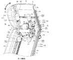
図1〜図3の右図、図6〜図8に示す状態を、マッサージ機1の「第2の姿勢」とする。
なお、第1の姿勢と第2の姿勢については、本実施形態を説明する上での例示であり、これらの姿勢(傾斜角度)に限定されない。つまり、これらの姿勢の他に、複数の姿勢を有するようにしてもよい。
The states shown on the right side of FIGS. 1 to 3 and the states shown in FIGS. 6 to 8 are referred to as the "second posture" of the
The first posture and the second posture are examples for explaining the present embodiment, and are not limited to these postures (tilt angles). That is, in addition to these postures, a plurality of postures may be held.
図1などに示すように、本実施形態のマッサージ機1は、使用者が着座可能な座部2と、その座部2と後端側から上方に向かって延びるように設けられている背もたれ部3とを有していて、座部2に着座し、背もたれ部3に凭れ掛かった使用者の首筋や肩部から腰部に掛けてマッサージするものである。
つまり、このマッサージ機1を使用する際には、使用者は、座部2に腰を下ろし、背もたれ部3に背部をつけるようにして着座し、背もたれ部3の内部に収容されたマッサージ機構30を用いて、使用者の首筋や肩部から腰部にかけて施療する、すなわち背部(施療部)に対してマッサージを受けることとなる。
As shown in FIG. 1 and the like, the
That is, when using this
なお、このマッサージ機1について、例えば、リクライニング可能な場合、背もたれ部3のさまざまな姿勢(傾斜姿勢や起立姿勢など)において、使用者の背部に対してマッサージが可能である。
座部2は、使用者が座ることができる程度の面積を有し、座面(上面)側にはクッション材が備えられている。
Regarding the
The
背もたれ部3は、前後方向を向いて起立するように、座部2の後端側に配備されていて、使用者の背部(腰部〜肩部)を全面に亘って覆うように支持する部材である。この背もたれ部3は、幅が使用者の肩幅よりやや広く、且つ、上下方向に長尺な板形状(プレート形状)であり、内部が空洞となった筐体である。また、背もたれ部3は、前後方向の厚みが幅方向に比して薄いものとなっている。
The
すなわち、背もたれ部3は、使用者の背部に沿うように配備される。背もたれ部3は、上下方向に長尺で板状の基盤体6(後側カバー)と、その基盤体6の前面を覆う被覆体7(前側カバー)とを有している。
基盤体6は、前後方向の厚みが薄く、且つ、上下方向に長尺な板状に形成されている。言い換えれば、基盤体6は、前方に向かって開口し、且つ浅い凹状に形成されているともいえる。
That is, the
The
その基盤体6の前面には、マッサージ機構30(詳細は後述)が上下方向に移動自在に取り付けられている。つまり、基盤体6の前面に配備されたマッサージ機構30は、移動駆動部13(詳細は後述)により所定の軌道23に沿って、当該軌道23の一方側から他方側(上下方向)へと移動する。
被覆体7は、前後方向の厚みが薄く、且つ、基盤体6と同様に上下方向に長尺な板状に形成されている。言い換えれば、被覆体7は、後方に向かって開口し、且つ浅い凹状に形成されているともいえる。
A massage mechanism 30 (details will be described later) is attached to the front surface of the
The covering
すなわち、被覆体7は、基盤体6の前面を全面に亘って覆うことで、基盤体6の前方を向く開口を閉鎖する。
また、被覆体7の幅方向の中央側には、上下方向に沿い、前方に向かって開口する開口部8が形成されている。
開口部8は、幅が被覆体7の幅よりも左右方向に狭く、且つ、長さが被覆体7の上下方向と同じものとされている。つまり、開口部8を正面から見た場合、上下方向に長い帯状に開口とされている。
That is, the covering
Further, on the central side of the covering
The width of the
この開口部8に沿って、マッサージ機構30が基盤体6の前面上(背もたれ部3の内部)を上下方向(長手方向)自在に移動する。すなわち、開口部8は、マッサージ機構30が上下に移動する移動エリアとなっている。
また、開口部8は、マッサージ機構30が使用者の背部(施療部)に直接当たらないように、布状の表カバー体(図示せず)などにより隙間なく覆われている。
Along the
Further, the
すなわち、背もたれ部3は、基盤体6と被覆体7とが、前後方向に重ね合わされ、その重ね合わされた内部に空間が形成される。背もたれ部3は、上下に長い開口部8に沿って移動可能にマッサージ機構30を収容する。また、被覆体7の開口部8は、マッサージ機構30の施療子33が前方に突出するように配備され、表カバー体などで閉鎖される。
図1〜図6などに示すように、本実施形態においては、背もたれ部3は、使用者の肩部から腰部に掛けて支持する本体部4と、首筋から頭部に掛けて支持するヘッドレスト部5(揺動部)とに、上下に二分割されている。ヘッドレスト部5は、本体部4に対して揺動可能とされている。
That is, in the
As shown in FIGS. 1 to 6, in the present embodiment, the
これら、本体部4とヘッドレスト部5との間には、ヘッドレスト部5を本体部4に対して所定の方向に揺動させて所定の姿勢にて係合する姿勢変更部9が左右一対設けられている。
なお、基盤体6については、本体部4側を第1基盤体6aとし、ヘッドレスト部5側を第2基盤体6bとする。また同様に、被覆体7のうち、本体部4側を第1被覆体7aとし、ヘッドレスト部5側を第2被覆体7bとする。開口部8についても同様に、本体部4側を第1開口部8aとし、ヘッドレスト部5側を第2開口部8bとする。
A pair of left and right
Regarding the
図1に示すように、姿勢変更部9は、ヘッドレスト部5(揺動部)を本体部4に対して揺動自在に支持し、所定の姿勢でヘッドレスト部5を係合するものである。姿勢変更部9は、傾斜度合いを変更することで、揺動部5の姿勢を複数の方向にて維持する。
この姿勢変更部9は、本体部4とヘッドレスト部5との間であって、ヘッドレスト部5の少なくとも左右一方側に配備されている。
As shown in FIG. 1, the
The
姿勢変更部9は、ヘッドレスト部5に設けられていて、ヘッドレスト部5が所定の姿勢に変更されると係合される係合部材10と、係合部材10を左右方向を向く軸心回りに揺動自在に支持する支持軸11と、本体部4に設けられていて、支持軸11を支持する支持部材12と、を有している。
この姿勢変更部9は、本体部4の支持部材12と、ヘッドレスト部5の係合部材10とを係合させることで、ヘッドレスト部5を前後方向における所定の姿勢(マッサージ位置)にて揺動を停止させてその姿勢を維持することを可能とする構成とされている。
The
The
姿勢変更部9は、例えば、ヘッドレスト部5を後方に揺動させて本体部4の傾斜と同じ傾斜にした姿勢(第1の姿勢)や、ヘッドレスト部5を前方に揺動させて屈めた姿勢(第2の姿勢)などの複数の姿勢に変更する。なお、ヘッドレスト部5の姿勢については、例示したものに限定されない。
なお、姿勢変更部9の構成について、ヘッドレスト部5を前後方向の所定の姿勢となる位置にて固定し、別の姿勢に切り替えるときには、ヘッドレスト部5の固定を解除できる構成であれば、特に限定はしない。
The
The configuration of the
例えば、姿勢変更部9に、ヘッドレスト部5の傾斜度合いを複数の方向に変更することが可能なラチェット機構などを採用してもよい。
さて、本実施形態のマッサージ機構30には、当該マッサージ機構30を上下方向に移動させる移動駆動部13が備えられている。
図1〜図6などに示すように、移動駆動部13は、マッサージ機構30の駆動部の下側に備えられていて、マッサージ機構30を昇降及び下降させる昇降部14と、マッサージ機構30を昇降部材18に沿って案内する案内部21と、を有している。
For example, the
By the way, the
As shown in FIGS. 1 to 6, the moving
昇降部14は、回転駆動力を発生する昇降モータ15と、回転駆動力を所定の速度に減速するギアボックス16と、回転駆動力により回転する回転軸17と、回転駆動力を昇降動作に変換する昇降部材18と、を有している。
昇降モータ15は、出力軸15aが左方向を向き、出力軸15aは側方のギアボックス16内に挿入されている。ギアボックス16は、回転軸17(昇降軸)が出力軸15aの下側であって、左右方向に貫通している。ギアボックス16は、出力された回転駆動力を所定の速度に減速して、昇降軸に伝達する。
The elevating
In the elevating
昇降軸は、軸心が軌道23(詳細は後述)の方向に対して交差する方向(左右方向)に配備されていて、その長手方向中央にギアボックス16が配備されている。つまり、昇降軸は、ギアボックス16を介して昇降モータ15と接続されている。昇降軸の端部側には、昇降部材18が設けられている。
昇降部材18は、昇降軸に設けられた駆動部材19と、駆動部材19が移動する駆動レール部材20とを有している。なお、本実施形態においては、駆動部材19をピニオンギアとし、駆動レール部材20をラックギアとしている。
The elevating shaft is arranged in a direction (left-right direction) in which the axis intersects the direction of the track 23 (details will be described later), and the
The elevating
ピニオンギア19は、昇降軸の両端部側にそれぞれ取り付けられていて、昇降軸の回転と共に回転する。ピニオンギア19と対面する第1基盤体6aの前面には、ラックギア20が配備されている。
ラックギア20は、ラック歯が上下方向に沿って直線上に並んで配備されているものであり、ピニオンギア19が歯合する。ピニオンギア19がラックギア20上を移動することで、昇降軸の回転駆動力が上下方向の直線移動の動作に変換され、マッサージ機構30が背もたれ部3内において上昇・下降することとなる。
The pinion gears 19 are attached to both ends of the elevating shaft, and rotate with the rotation of the elevating shaft. A
The
昇降部材18の左右方向外側には、マッサージ機構30を上下方向に案内する案内部21が配備されている。
案内部21は、マッサージ機構30の側方(昇降軸の両端部など)に取り付けられている案内部材22と、案内部材22を一方側から他方側へと案内する軌道23と、を有している。
A
The
図3〜図8などに示すように、案内部材22は、軸心が左右方向を向き、軌道23内に転動乃至は摺動自在に嵌入されるローラ部材22である。ローラ部材22は、直径が軌道23内の高さ(溝高さ)と略同じであり、軸方向の高さが軌道23内の深さ(溝深さ)より大きいものとなっている。これにより、ローラ部材22は軌道23内を移動することができるようになっている。
As shown in FIGS. 3 to 8, the
このローラ部材22は、マッサージ機構30(ケーシング41)の上部の左右両側に(上部ローラ部材22a)一対備えられ、下部の左右両側(昇降軸の左右両端部)に一対(下部ローラ部材22b)備えられている。つまり、ローラ部材22は、マッサージ機構30の略四隅にそれぞれ備えられているものである。
軌道23は、ローラ部材22が転動乃至は摺動自在に嵌り込むレール部材23である。なお、以降においては、軌道23をレール部材23として説明する。
A pair of roller members 22 (
The
このレール部材23は、姿勢変更部9によりヘッドレスト部5の位置が、第1の姿勢から第2の姿勢へと変更されると、その変更された方向に折れ曲げられて切り替わる構成となっている。
本実施形態のレール部材23は、第1レール部材24と第2レール部材25とからなるものであり、第1レール部材24と第2レール部材25とを長手方向に付き合わせることで形成されている。
When the position of the
The
また、本実施形態においては、これらの二つのレール部材24,25のうち、第2レール部材25が第1レール部材24に対して前後方向に折れ曲がり可能な構成としている。
つまり、第1レール部材24と第2レール部材25は、第1の姿勢に変更されたとき、付き合わされた部位が近接する。また、その付き合わされた部位は、第2の姿勢に変更されたとき、離反する。
Further, in the present embodiment, of these two
That is, when the
第1レール部材24は、第1開口部8a(本体部4)の左右両側に一対設けられていて、ラックギア20と平行に配備されている。第1レール部材24の長さは、第1開口部8aの長手方向(上下方向)の長さとほぼ同じである。
第1レール部材24は、前側壁24aと後側壁24bとの二つの側壁を有し、前側壁24aは第1被覆体7aに形成され、後側壁24bは第1基盤体6aに形成されている。第1レール部材24の前側壁24aと後側壁24bは、前後方向において対面するように配備されている。また、それら前側壁24aと後側壁24bとの間隔(溝の幅)は、ローラ部材22の直径と略同じものとされている。
A pair of
The
第2レール部材25は、第2開口部8b(ヘッドレスト部5)の左右両側に一対設けられている。第2レール部材25の長さは、第2開口部8bの長手方向(上下方向)の長さとほぼ同じである。
第2レール部材25は、前側壁25aと後側壁25bとの二つの側壁を有し、前側壁25aは第2被覆体7bに形成され、後側壁25bは第2基盤体6bに形成されている。第2レール部材25の前側壁25aと後側壁25bは、前後方向において対面するように配備されている。また、それら前側壁25aと後側壁25bとの間隔(溝の幅)は、ローラ部材22の直径と略同じものとされている。
A pair of
The
第1レール部材24及び第2レール部材25の幅(溝の深さ)については、ローラ部材22の外周面が十分に接することができるものとされている。
第1レール部材24の上部と第2レール部材25の下部との間には、マッサージ機構30の移動方向を切り替える切り替え機構26が設けられている。
図3〜図8などに示すように、切り替え機構26は、第1レール部材24と第2レール部材25の屈曲度合いを変更することで、マッサージ機構30の移動方向を複数の方向に切り替えるものである。
Regarding the width (groove depth) of the
A
As shown in FIGS. 3 to 8, the
切り替え機構26は、第1レール部材24と第2レール部材25の屈曲度合いを変更した際に、その第1レール部材24と第2レール部材25上に存在する屈曲部位を、マッサージ機構30が連続的に移動することを可能とする「接続部27」を有している。
この接続部27は、第1レール部材24の上端部と第2レール部材25の下端部が付き合わさった部位において、屈曲してもローラ部材22が連続的に走行することが可能となる繋ぎ目となった部位のことである。
In the
The connecting
すなわち、切り替え機構26は、接続部27において、第2レール部材25(又は第1レール部材24)を長手方向に直交する軸心回り(姿勢変更部9の支持軸11の軸心回り)に揺動させることにより、第1レール部材24と第2レール部材25の屈曲度合いを変更するものである。
その接続部27をローラ部材22が連続的に接しながら移動することで、ローラ部材22は第1レール部材24及び第2レール部材25から離れることなく案内されるので、マッサージ機構30が第1レール部材24から当該接続部27を経て第2レール部材25へと連続的に移動する。
That is, the
By moving the
切り替え機構26は、例えば、ヘッドレスト部5が姿勢変更部9により、図4、図5などに示す「第1の姿勢」から、図6、図7などに示す「第2の姿勢」に変更されると、複数の移動方向のうち、ヘッドレスト部5と同じ方向(前方向)に第2レール部材25を傾斜させて、接続部27を屈曲状態にする。その屈曲部位が形成された接続部27を、マッサージ機構30を第1レール部材24と第2レール部材25との間で、途切れなく案内可能とする「乗り換え部位」とするものである。
In the
すなわち、切り替え機構26は、ローラ部材22が、第1レール部材24と第2レール部材25の両方に接触しない「非接触区間」を設けないようにするものである。
言い換えれば、ローラ部材22は、第1レール部材24を走行し終えると、切り替え機構26により乗り換え可能となった屈曲部位の接続部27を通過することで、直ちに第2レール部材25を走行することができる。
That is, the
In other words, when the
なお、接続部27より反第2レール部材25側に離れた位置に、ラックギア(駆動レール部材20)の上端部が配備されている。
図4〜図8などに示すように、接続部27は、第1レール部材24から長手方向に突出する第1接続片28と、第1接続片28と反対方向であって、第2レール部材25から長手方向に突出する第2接続片29を有している。
The upper end of the rack gear (drive rail member 20) is provided at a position away from the connecting
As shown in FIGS. 4 to 8, the connecting
詳しくは、第1接続片28と第2接続片29は、正面視で、互い違いとなるように配備されている。例えば、第1接続片28が第1レール部材24の右側から上方に延設されている場合、第2接続片29は第2レール部材25の左側から下方に延設される。なお、第1接続片28と第2接続片29については、逆の配備位置(左右逆に配置)でも構わない。
Specifically, the
また、第1接続片28と第2接続片29は、側面視においてオーバーラップする(重なり合う)ように配備されている(図5、図7など参照)。つまり、第1接続片28の案内面28bの上端と、第2接続片29の案内面29bの下端が、第1レール部材24と第2レール部材25が屈曲された状態でも重なるようになっている。ここが接続部27であり、ローラ部材22が第1レール部材24から第2レール部材25へと移るための「乗り換え区間」となる。
Further, the
第1接続片28の外側を向く側面28aと、第2接続片29の内側を向く側面29aは、互いに向き合うように配備されている。また、第1接続片28の前方を向く案内面28bと、第2接続片29の前方を向く案内面29bとは、連続的に接続された状態となっていて、第1接続片28の案内面28bと第2接続片29の案内面29bとの少なくとも一方は、ローラ部材22に常に接する状態とされている。
The
すなわち、第1接続片28と第2接続片29は、左右方向において、互いに付き合わされるように備えられていて、第1レール部材24と第2レール部材25の屈曲角が如何なるものであっても接する状態を維持する。
例えば、第1レール部材24と第2レール部材25が屈曲状態において、第1レール部材24内を走行するローラ部材22が第2レール部材25へ移る際には、接続部27において、ローラ部材22が第1接続片28の案内面28bと接触し終わろうとすると、第2接続片29の案内面29bと接触し始めることとなる。
That is, the first connecting
For example, when the
これにより、マッサージ機構30は、第1レール部材24及び第2レール部材25上を、一方側(上方側)から他方側(下方側)乃至は他方側から一方側へと移動する。
つまり、接続部27においては、ローラ部材22が第1接続片28の案内面28bと第2接続片29の案内面29bの両方に接触する区間がある。
また、ローラ部材22が接続部27を連続的に移動して、マッサージ機構30が第1レール部材24から当該接続部27を経て第2レール部材25へと移動した際には、移動駆動部13の回転駆動力を伝える回転軸17(昇降軸)の軸心周りに、マッサージ機構30が傾くようになっている。
As a result, the
That is, in the connecting
Further, when the
つまり、マッサージ機構30は、移動駆動部13の回転軸17(昇降軸)の軸心周りに、揺動自在に支持されている。
このように、マッサージ機構30は、切り替え機構26による移動方向の切り替えと、移動駆動部13による上昇により、回転軸17(昇降軸)の軸心周りに揺動するようになるので、背もたれ部3より前方へ突出することができる。
That is, the
In this way, the
次に、マッサージ機構30の構成の概略について、説明する。
なお、以降に説明するマッサージ機構30の基本的な装置構成については、例えば、特開2011−131039号公報に記載の構成などとほぼ同じである。
図2、図4、図6などに示すように、本実施形態のマッサージ機構30は、施療部(背部)に対してマッサージ動作を付与するマッサージ部材31と、マッサージ部材31の基端側を貫通するマッサージ回転軸34と、マッサージ回転軸34を回転駆動させる駆動部35と、マッサージ回転軸34の回転力をマッサージ動作に変換する変換部38と、マッサージ部材31を上下方向に移動させる移動駆動部13と、を有している。
Next, the outline of the configuration of the
The basic device configuration of the
As shown in FIGS. 2, 4, 6, and the like, the
マッサージ部材31は、左右方向に所定の間隔を空けて一対配備されている。マッサージ部材31は、駆動部35から使用者側に向かって(前方に向かって)突出するアーム部材32を有している。
アーム部材32は、先端が斜め前上方と斜め前下方との2方向に分かれて突出しており、分岐した上側の先端と下側の先端とのそれぞれに施療子33が配備されている。このアーム部材32の長手方向中途部は、マッサージ部材31の基端とされている。
A pair of
The tip of the
施療子33は、肩などの使用者の背部(施療部)をマッサージするものであり、球体状に形成された部材である。
この左右一対のマッサージ部材31が互いに近接離反すると、左側の施療子33と右側の施療子33が左右方向に近接離反を繰り返すことにより、施療部に対してマッサージを行う。
The
When the pair of left and
マッサージ回転軸34は、軸心が水平方向を向くように配備され且つ、ケーシング41に設けられた支持部42により回転自在に支持されている。マッサージ回転軸34は、マッサージ部材31の基端に設けられている変換部38を左右方向に亘って貫通している。
駆動部35は、ケーシング41内であって、左右一対のマッサージ部材31の間に配備されている。駆動部35は、回転駆動力を発生する駆動モータ36と、回転駆動力を所定の速度に減速して、マッサージ回転軸34に伝達するギアボックス37と、を有している。
The
The
駆動モータ36は、出力軸36aが左方向を向き、出力軸36aは側方のギアボックス37内に挿入されている。ギアボックス37は、マッサージ回転軸34が出力軸36aの下側であって、左右方向に貫通している。ギアボックス37は、出力された回転駆動力を所定の速度に減速して、マッサージ回転軸34に伝達する。
変換部38は、マッサージ回転軸34の回転力を、マッサージ部材31のマッサージ動作(近接離反動作)に変換するものである。変換部38は、一対のマッサージ部材31の基端側にそれぞれ設けられていて、マッサージ回転軸34が回転自在に貫通している。
In the
The
変換部38は、マッサージ回転軸34と一体回転する傾斜ボス部39と、マッサージ部材31の基端に設けられ、傾斜ボス部39を外嵌する環状嵌合部40と、マッサージ部材31がマッサージ回転軸34との同伴回転することを規制する規制部(図示せず)と、を有している。
傾斜ボス部39は、マッサージ回転軸34を外嵌しており、そのマッサージ回転軸34と共に回転する。傾斜ボス部39の外周面には、マッサージ回転軸34に対して傾斜状のカム面が設けられている。傾斜ボス部39は、マッサージ回転軸34の軸心に対して傾斜回転する。なお、傾斜ボス部39(カム面)の傾きは、左右一対のマッサージ部材31間において、相対逆向きに、互いに傾斜している。
The
The
環状嵌合部40は、マッサージ部材31の基端に形成されていて、傾斜ボス部39を相対回転自在な状態で外嵌する。環状嵌合部40が、傾斜回転する傾斜ボス部39を回転自在に外嵌することにより、マッサージ部材31が揺動運動をする。
規制部は、環状嵌合部40が傾斜ボス部39に対して供回りすることを規制するものであり、その環状嵌合部40の後側(ケーシング41側)に配備されている。規制部は、環状嵌合部40に設けられた規制ピンと、規制ピンが摺動自在に嵌り込む規制溝と、を有している。
The annular
The restricting portion restricts the annular
規制ピンは、環状嵌合部40から前方向に突出しているマッサージ部材31の反対方向(後方向)に突設されている。規制溝は、左右方向に長いものであり、規制ピンと対面するケーシング41に設けられている。規制溝には、規制ピンが摺動自在に挿入され、規制ピンが左右方向に揺動する。
なお、移動駆動部13については、上で述べた通りである。
The regulation pin is projected in the opposite direction (rear direction) of the
The moving
以下に、本実施形態のマッサージ機1の作動態様について、説明する。
まず、図3の左図、図4、図5など参照しながら、「第1の姿勢」のときの状況について説明する。
ヘッドレスト部5は、姿勢変更部9により、本体部4の傾斜と同じ傾斜の「第1の姿勢」の状態とされる。
The operation mode of the
First, the situation in the "first posture" will be described with reference to the left figure of FIG. 3, FIGS. 4, 5 and the like.
The
切り替え機構26は、ヘッドレスト部5の姿勢に合わせて、第1レール部材24と同一直線(同一軌道)上となるように、第2レール部材25を後方に傾ける。
図4、図5に示すように、このとき、第1レール部材24と第2レール部材25が付き合わされ、第1接続片28の案内面28bと第2接続片29の案内面29bとが面一となっている。この二つの案内面28b,29bが面一となった部位が接続部27である。
The
As shown in FIGS. 4 and 5, at this time, the
また、側面視で、第1接続片28の側面28aと第2接続片29の側面29aは、重なり合っている(オーバーラップ)部分が大きい。第1レール部材24〜接続部27〜第2レール部材25は、軌道23が一本に繋がった状態となっている。
この状態で、移動駆動部13を動作させて、マッサージ機構30を第1レール部材24に沿って上昇させると、マッサージ機構30の上部ローラ部材22aは、第1レール部材24内を走行する。続いて、上部ローラ部材22aが第1レール部材24の上部に差し掛かると、第1接続片28と第2接続片29が大きく重なる接続部27を走行することとなる。接続部27を走行し終えると、上部ローラ部材22aは、第2レール部材25内を走行する。
Further, in a side view, the
In this state, when the moving
このようにして、ローラ部材22は、第1レール部材24〜接続部27〜第2レール部材25を連続的に滑らかに走行することとなる。
まず、図3の右図、図6〜図8など参照しながら、「第2の姿勢」のときの状況について説明する。
ヘッドレスト部5は、姿勢変更部9により、前屈みの「第2の姿勢」の状態となる。
In this way, the
First, the situation in the "second posture" will be described with reference to the right figure of FIG. 3, FIGS. 6 to 8, and the like.
The
切り替え機構26は、ヘッドレスト部5の前屈みの姿勢に合わせて、第2レール部材25を前方へ傾ける。
つまり、ヘッドレスト部5の姿勢が、姿勢変更部9により変更されると、切り替え機構26は、第2レール部材25の屈曲度合いを変更する。
図6、図7に示すように、このとき、第1レール部材24と第2レール部材25からなる軌道23は、後方に屈曲したL字状となる。このときの屈曲部位が接続部27である。
The
That is, when the posture of the
As shown in FIGS. 6 and 7, at this time, the
この接続部27においては、第1接続片28の案内面28bの上端と、第2接続片29の案内面29bの下端が、側面視で、オーバーラップしている。この「第2の姿勢」のときのオーバーラップ部分については、「第1の姿勢」のときより小さいものの、ローラ部材22が連続的に走行可能なものとなっている。
すなわち、第1レール部材24〜接続部27〜第2レール部材25からなる軌道23は、屈曲された状態でも、第1接続片28と第2接続片29がローラ部材22の走行方向において重なり合って、途切れることなく一本に繋がった状態となっている(図7、図8など参照)。
In the
That is, even in the bent state of the
この状態で、移動駆動部13を動作させて、マッサージ機構30を第1レール部材24に沿って上昇させると、マッサージ機構30の上部ローラ部材22aは、第1レール部材24内を走行する。続いて、上部ローラ部材22aが第1レール部材24の上部に差し掛かると、第1接続片28を走行することとなる。
さらに、上部ローラ部材22aが第1接続片28の上端に差し掛かると、第2接続片29の下端と重なり且つ、屈曲部位である「接続部27」に接触して走行することとなる。
In this state, when the moving
Further, when the
すなわち、上部ローラ部材22aは、第1接続片28と第2接続片29の両方に接触して、「接続部27」を連続的に走行することとなる。
上部ローラ部材22aは、第1接続片28(接続部27)から離れると、既に接触している第2接続片29を走行し、その後第2レール部材25内を走行する。
マッサージ機構30は、移動駆動部13により、本体部4からヘッドレスト部5へ上昇して連続的に移動すると共に、昇降軸(下部ローラ部材22b)の軸心回りに前方へ揺動することとなる。
That is, the
When the
The
このとき、マッサージ部材31の施療子33が本体部4及びヘッドレスト部5より前方へ突出し、所定のマッサージ位置に切り替えられる。
以上述べたように、本実施形態のマッサージ機1の特徴は、移動駆動部13により、マッサージ機構30を所定の軌道23(レール部材)に沿って、一方側から他方側へと移動させるとき、軌道23の屈曲度合いを変更することで、マッサージ機構30の移動方向を切り替えることができる切り替え機構26を有していることにある。
At this time, the
As described above, the feature of the
つまり、本実施形態のマッサージ機1は、ヘッドレスト部5を傾斜させた方向に、マッサージ機構30の移動させることができる機能を有している。
さらに、マッサージ機構30を一方側から他方側へと移動させるとき、移動方向を滑らかに移行させることができる切り替え部位(接続部27)が備えられていることも特徴である。
That is, the
Further, when the
このような、軌道23及び切り替え機構26を備えることにより、マッサージの位置を容易に切り替えることができると共に、使用者にさまざまなマッサージ効果を付与することができる。また、装置全体をシンプルで且つコンパクトなものとすることができる。
なお、本実施形態で説明した軌道23及び切り替え機構26の構成については、一例であり、これに限定されない。
By providing such a
The configuration of the
なお、今回開示された実施形態はすべての点で例示であって制限的なものではないと考えられるべきである。
例えば、駆動部材19が設けられた回転軸17(昇降軸)と、マッサージ機構30に設けられ且つ施療部に対してマッサージ動作を付与するマッサージ回転軸34とを有し、回転軸17(昇降軸)とマッサージ回転軸34とが同一乃至は同軸に設けられていてもよい。
It should be noted that the embodiments disclosed this time are exemplary in all respects and are not considered to be restrictive.
For example, it has a rotating shaft 17 (elevating shaft) provided with a driving
本実施形態においては、レール部材23(軌道)を、第1レール部材24と第2レール部材25とに分割されたものとしたが、折り曲げ可能な一本のレール部材としててもよい。
特に、今回開示された実施形態において、明示されていない事項、例えば、作動条件や操作条件、構成物の寸法、重量などは、当業者が通常実施する範囲を逸脱するものではなく、通常の当業者であれば、容易に想定することが可能な事項を採用している。
In the present embodiment, the rail member 23 (track) is divided into a
In particular, in the embodiments disclosed this time, matters not specified, for example, operating conditions, operating conditions, dimensions of components, weight, etc., do not deviate from the range normally practiced by those skilled in the art, and are normal. If you are a person skilled in the art, you are adopting items that can be easily assumed.
1 マッサージ機
2 座部
3 背もたれ部
4 本体部
5 ヘッドレスト部
6 基盤体
6a 第1基盤体
6b 第2基盤体
7 被覆体
7a 第1被覆体
7b 第2被覆体
8 開口部
8a 第1開口部
8b 第2開口部
9 姿勢変更部
10 係合部材
11 支持軸
12 支持部材
13 移動駆動部
14 昇降部
15 昇降モータ
15a 出力軸
16 ギアボックス
17 回転軸(昇降軸)
18 昇降部材
19 駆動部材(ピニオンギア)
20 駆動レール部材(ラックギア)
21 案内部
22 案内部材(ローラ部材)
22a 上部ローラ部材
22b 下部ローラ部材
23 軌道(レール部材)
24 第1レール部材
24a 前側壁
24b 後側壁
25 第2レール部材
25a 前側壁
25b 後側壁
26 切り替え機構
27 接続部
28 第1接続片
28a 側面
28b 案内面
29 第2接続片
29a 側面
29b 案内面
30 マッサージ機構
31 マッサージ部材
32 アーム部材
33 施療子
34 マッサージ回転軸
35 駆動部
36 駆動モータ
36a 出力軸
37 ギアボックス
38 変換部
39 傾斜ボス部
40 環状嵌合部
41 ケーシング
42 支持部
1
18 Lifting
20 Drive rail member (rack gear)
21
22a
24
Claims (5)
前記マッサージ機構は、前記軌道に交差する方向に配備され且つ前記移動駆動部の回転駆動力を伝える回転軸と、前記回転軸の両端に設けられた案内部材とを有し、
前記切り替え機構は、前記軌道の屈曲度合いを変更した際に、当該軌道上に存在する屈曲部位を前記マッサージ機構が連続的に移動することを可能とする接続部を有し、
前記軌道は、第1軌道と第2軌道とを長手方向に付き合わせることで形成されており、前記付き合わさった部位に前記接続部が形成されていて、前記接続部において、前記第1軌道又は前記第2軌道を長手方向に直交する軸心回りに揺動させることにより、前記軌道の屈曲度合いを変更可能に構成されており、
前記軌道は、第1レール部材と第2レール部材とを長手方向に付き合わせることで形成されており、前記マッサージ機構は、前記第1レール部材及び前記第2レール部材上を前記案内部材が転動乃至は摺動するものとされ、前記案内部材が前記接続部を連続的に移動することで、前記マッサージ機構が前記第1レール部材から前記第2レール部材へと連続的に移動するものであり、
前記接続部においては、前記第1レール部材は長手方向に突出し且つ前記案内部材が上面を転動する第1接続片を有し、前記第2レール部材は長手方向に突出し且つ前記案内部材が上面を転動する第2接続片を有し、前記第1接続片及び前記第2接続片は、側面視においてオーバーラップするように配備されていて、前記第1接続片の側面と前記第2接続片の側面とは、前記軌道の屈曲角が如何なるものであっても接する状態を維持し、前記第1接続片の案内面と前記第2接続片の案内面とは、連続的に接続された状態となっていて、前記第1接続片の案内面と前記第2接続片の案内面との少なくとも一方は、前記案内部材に接する
ことを特徴とするマッサージ機。 A massage mechanism that imparts a massage operation to the treatment unit, a moving drive unit that moves the massage mechanism from one side to the other along a predetermined trajectory, and a degree of bending of the trajectory are changed. As a result, it has a switching mechanism that switches the moving direction of the massage mechanism to a plurality of directions.
The massage mechanism has a rotation shaft that is arranged in a direction intersecting the trajectory and transmits a rotation driving force of the movement drive unit, and guide members provided at both ends of the rotation shaft.
The switching mechanism has a connecting portion that enables the massage mechanism to continuously move to a bending portion existing on the orbit when the degree of bending of the orbit is changed.
The track is formed by associating the first orbit and the second orbit in the longitudinal direction, and the connecting portion is formed at the mated portion, and the first orbit or the first orbit or the first orbit or the second orbit is formed at the connecting portion. By swinging the second trajectory around an axis orthogonal to the longitudinal direction, the degree of bending of the trajectory can be changed.
The track is formed by associating the first rail member and the second rail member in the longitudinal direction, and in the massage mechanism, the guide member rolls on the first rail member and the second rail member. It is assumed to move or slide, and when the guide member continuously moves through the connection portion, the massage mechanism continuously moves from the first rail member to the second rail member. Yes,
In the connecting portion, the first rail member has a first connecting piece that projects in the longitudinal direction and the guide member rolls on the upper surface, and the second rail member projects in the longitudinal direction and the guide member. Has a second connecting piece that rolls on the upper surface, and the first connecting piece and the second connecting piece are arranged so as to overlap in a side view, and the side surface of the first connecting piece and the first connecting piece are arranged so as to overlap each other. The side surface of the two connection pieces is maintained in contact with any bending angle of the track, and the guide surface of the first connection piece and the guide surface of the second connection piece are continuously connected. A massage machine characterized in that at least one of the guide surface of the first connecting piece and the guide surface of the second connecting piece is in contact with the guide member.
前記駆動部材により伝えられる回転駆動力により、前記マッサージ機構を前記軌道の一
方側から他方側乃至は他方側から一方側へと移動する構成とされ、
前記案内部材が前記接続部を連続的に移動して、前記マッサージ機構が前記第1レール部材から前記第2レール部材へと移動した際には、前記移動駆動部の回転駆動力を伝える前記回転軸の軸心周りに、前記マッサージ機構が傾くように構成されている
ことを特徴とする請求項1に記載のマッサージ機。 The massaging mechanism includes a driving member provided on the front Symbol rotation axis,
The massage mechanism is configured to move from one side of the track to the other side or from the other side to one side by the rotational driving force transmitted by the driving member.
When the guide member continuously moves through the connection portion and the massage mechanism moves from the first rail member to the second rail member, the rotation that transmits the rotational driving force of the moving driving portion. The massage machine according to claim 1, wherein the massage mechanism is configured to be tilted around the axis of the shaft.
ことを特徴とする請求項2に記載のマッサージ機。 The drive rail member included in the drive member is arranged along the first rail member, and the end portion of the drive rail member is arranged at a position away from the connection portion on the anti-second rail member side. The massage machine according to claim 2, wherein the massage machine is provided.
前記本体部には、前記第1レール部材が設けられていて、
前記揺動部には、前記第2レール部材が設けられていて、
前記揺動部の姿勢が前記姿勢変更部により変更されると、前記第2レール部材の屈曲度合いが前記切り替え機構により変更され、前記マッサージ機構が前記本体部から前記揺動部へと連続的に移動する
ことを特徴とする請求項1に記載のマッサージ機。 The main body provided with the massage mechanism, the swinging portion capable of swinging with respect to the main body, and the posture of the swinging portion are swung in a predetermined direction with respect to the main body. Has a posture change part to change
The first rail member is provided on the main body portion, and the first rail member is provided.
The swing portion is provided with the second rail member.
When the posture of the swinging portion is changed by the posture changing portion, the degree of bending of the second rail member is changed by the switching mechanism, and the massage mechanism continuously moves from the main body portion to the swinging portion. The massage machine according to claim 1, wherein the massage machine is moved.
ことを特徴とする請求項4に記載のマッサージ機。 The massage machine according to claim 4, wherein the posture changing portion is a ratchet mechanism capable of changing the inclination degree of the swinging portion in a plurality of directions.
Priority Applications (6)
| Application Number | Priority Date | Filing Date | Title |
|---|---|---|---|
| JP2018079824A JP6852903B2 (en) | 2018-04-18 | 2018-04-18 | Massage machine |
| CN201980000907.9A CN110621281A (en) | 2018-04-18 | 2019-02-08 | Massage device |
| PCT/JP2019/004618 WO2019202825A1 (en) | 2018-04-18 | 2019-02-08 | Massage machine |
| SG11202000310QA SG11202000310QA (en) | 2018-04-18 | 2019-02-08 | Massage machine |
| KR1020207010780A KR20200055039A (en) | 2018-04-18 | 2019-02-08 | Massager |
| TW108106182A TWI714000B (en) | 2018-04-18 | 2019-02-23 | Massage machine |
Applications Claiming Priority (1)
| Application Number | Priority Date | Filing Date | Title |
|---|---|---|---|
| JP2018079824A JP6852903B2 (en) | 2018-04-18 | 2018-04-18 | Massage machine |
Publications (2)
| Publication Number | Publication Date |
|---|---|
| JP2019187490A JP2019187490A (en) | 2019-10-31 |
| JP6852903B2 true JP6852903B2 (en) | 2021-03-31 |
Family
ID=68239480
Family Applications (1)
| Application Number | Title | Priority Date | Filing Date |
|---|---|---|---|
| JP2018079824A Active JP6852903B2 (en) | 2018-04-18 | 2018-04-18 | Massage machine |
Country Status (6)
| Country | Link |
|---|---|
| JP (1) | JP6852903B2 (en) |
| KR (1) | KR20200055039A (en) |
| CN (1) | CN110621281A (en) |
| SG (1) | SG11202000310QA (en) |
| TW (1) | TWI714000B (en) |
| WO (1) | WO2019202825A1 (en) |
Families Citing this family (1)
| Publication number | Priority date | Publication date | Assignee | Title |
|---|---|---|---|---|
| CN113002392B (en) * | 2019-12-21 | 2022-09-02 | 芜湖瑞泰汽车零部件有限公司 | Car seat with back physiotherapy function |
Family Cites Families (9)
| Publication number | Priority date | Publication date | Assignee | Title |
|---|---|---|---|---|
| JP2003190243A (en) * | 2001-12-26 | 2003-07-08 | Marutaka Co Ltd | Mat type whole body massage machine |
| JP2011131039A (en) * | 2009-11-24 | 2011-07-07 | Daito Denki Kogyo Kk | Back massage device provided to chair type massage machine and chair type massage machine with same |
| JP2012217750A (en) * | 2011-04-13 | 2012-11-12 | Family Co Ltd | Massage machine |
| JP6470882B2 (en) | 2013-04-18 | 2019-02-13 | ファミリーイナダ株式会社 | Massage machine |
| CN105078697A (en) * | 2014-04-18 | 2015-11-25 | 宁波秉航电子科技有限公司 | Massage chair with rotary guide rail |
| KR20160085952A (en) * | 2015-01-08 | 2016-07-19 | 주식회사 바디프랜드 | Massage Apparatus with Folded Backrest |
| JP2017012735A (en) * | 2015-07-03 | 2017-01-19 | 大東電機工業株式会社 | Chair type massage machine and massage mechanism |
| CN105902009A (en) * | 2016-06-29 | 2016-08-31 | 林志强 | Back cushion for chair |
| CN107007438A (en) * | 2017-05-22 | 2017-08-04 | 林学金 | Massage armchair with segmented tracks |
-
2018
- 2018-04-18 JP JP2018079824A patent/JP6852903B2/en active Active
-
2019
- 2019-02-08 SG SG11202000310QA patent/SG11202000310QA/en unknown
- 2019-02-08 CN CN201980000907.9A patent/CN110621281A/en active Pending
- 2019-02-08 WO PCT/JP2019/004618 patent/WO2019202825A1/en active Application Filing
- 2019-02-08 KR KR1020207010780A patent/KR20200055039A/en not_active Application Discontinuation
- 2019-02-23 TW TW108106182A patent/TWI714000B/en active
Also Published As
| Publication number | Publication date |
|---|---|
| WO2019202825A1 (en) | 2019-10-24 |
| TW201943400A (en) | 2019-11-16 |
| CN110621281A (en) | 2019-12-27 |
| TWI714000B (en) | 2020-12-21 |
| SG11202000310QA (en) | 2020-02-27 |
| KR20200055039A (en) | 2020-05-20 |
| JP2019187490A (en) | 2019-10-31 |
Similar Documents
| Publication | Publication Date | Title |
|---|---|---|
| JP5892724B2 (en) | Chair type massage machine | |
| US20080077061A1 (en) | Kneading and rolling robotic massage device | |
| TWI632906B (en) | Massage machine | |
| JP4661302B2 (en) | Massage machine | |
| JP5408744B2 (en) | Massage machine | |
| JP6852903B2 (en) | Massage machine | |
| JP2017153733A (en) | Massage mechanism and chair-type massage machine including massage mechanism | |
| JP7121998B2 (en) | chair massage machine | |
| JP7340259B2 (en) | massage device | |
| KR20200140593A (en) | A Massage Ball Assembly capable of Massaging the Upper Shoulder, Massage Chair with the Massage Ball Assembly, and Massage Method using Massage Chair | |
| JP6750884B2 (en) | Massage device | |
| JP5268560B2 (en) | Chair massage machine | |
| TW201626972A (en) | Massage mechanism | |
| JP4507702B2 (en) | Massage machine | |
| JPH11244348A (en) | Massage machine | |
| JP6936477B2 (en) | Massage machine | |
| JP2014094061A (en) | Massage mechanism | |
| JP2008104765A (en) | Chair type massage machine and massage unit | |
| JP6997072B2 (en) | Massage machine | |
| WO2023149018A1 (en) | Massage device and massage unit | |
| WO2019159811A1 (en) | Chair-type massaging machine | |
| JP2021040692A (en) | Massage machine | |
| WO2018003076A1 (en) | Machine unit for massager | |
| JP2021078985A (en) | Massage machine | |
| JP5288651B2 (en) | Chair type massage machine |
Legal Events
| Date | Code | Title | Description |
|---|---|---|---|
| A621 | Written request for application examination |
Free format text: JAPANESE INTERMEDIATE CODE: A621 Effective date: 20191228 |
|
| A131 | Notification of reasons for refusal |
Free format text: JAPANESE INTERMEDIATE CODE: A131 Effective date: 20201110 |
|
| A521 | Request for written amendment filed |
Free format text: JAPANESE INTERMEDIATE CODE: A523 Effective date: 20201209 |
|
| A131 | Notification of reasons for refusal |
Free format text: JAPANESE INTERMEDIATE CODE: A131 Effective date: 20210119 |
|
| A521 | Request for written amendment filed |
Free format text: JAPANESE INTERMEDIATE CODE: A523 Effective date: 20210205 |
|
| TRDD | Decision of grant or rejection written | ||
| A01 | Written decision to grant a patent or to grant a registration (utility model) |
Free format text: JAPANESE INTERMEDIATE CODE: A01 Effective date: 20210302 |
|
| A61 | First payment of annual fees (during grant procedure) |
Free format text: JAPANESE INTERMEDIATE CODE: A61 Effective date: 20210304 |
|
| R150 | Certificate of patent or registration of utility model |
Ref document number: 6852903 Country of ref document: JP Free format text: JAPANESE INTERMEDIATE CODE: R150 |
|
| R250 | Receipt of annual fees |
Free format text: JAPANESE INTERMEDIATE CODE: R250 |