JP2007029481A - Massage machine - Google Patents
Massage machine Download PDFInfo
- Publication number
- JP2007029481A JP2007029481A JP2005218143A JP2005218143A JP2007029481A JP 2007029481 A JP2007029481 A JP 2007029481A JP 2005218143 A JP2005218143 A JP 2005218143A JP 2005218143 A JP2005218143 A JP 2005218143A JP 2007029481 A JP2007029481 A JP 2007029481A
- Authority
- JP
- Japan
- Prior art keywords
- massage
- treatment
- massage machine
- spine
- pair
- Prior art date
- Legal status (The legal status is an assumption and is not a legal conclusion. Google has not performed a legal analysis and makes no representation as to the accuracy of the status listed.)
- Pending
Links
- 238000011282 treatment Methods 0.000 claims description 100
- 230000000694 effects Effects 0.000 abstract description 11
- 230000007246 mechanism Effects 0.000 description 6
- 208000003251 Pruritus Diseases 0.000 description 3
- 230000007803 itching Effects 0.000 description 3
- 238000004898 kneading Methods 0.000 description 3
- 238000010079 rubber tapping Methods 0.000 description 3
- 230000002093 peripheral effect Effects 0.000 description 2
- 238000013459 approach Methods 0.000 description 1
- 230000000284 resting effect Effects 0.000 description 1
- 238000005201 scrubbing Methods 0.000 description 1
- 210000002784 stomach Anatomy 0.000 description 1
Images


Abstract
Description
本発明はマッサージ機に関する。さらに詳しくは、脊もたれ部内に昇降自在に配設された施療駆動部で被施療者の背中等のマッサージを行う椅子型のマッサージ機に関する。 The present invention relates to a massage machine. More specifically, the present invention relates to a chair-type massage machine that performs massage of the back of a user and the like with a treatment drive unit that is disposed so as to freely move up and down in the spine.
従来より、前記椅子型のマッサージ機においては、人間の手によるマッサージに近いマッサージ効果を得るために、揉み、叩き及び振動の各動作、並びにこれらの動作を適宜組み合わせた複合動作を行うことができる施療子を備えたものが知られている。この施療子は、マッサージ機の脊もたれ部内に昇降自在に配設された施療駆動部に設けられており、マッサージ機の座ベース部に座った被施療者の腰から首に至る範囲の所望部位をマッサージすることができるようになっている。
しかしながら、従来の施療駆動部は脊もたれ部の中央(脊もたれ部の幅方向又は左右方向、すなわちマッサージ機の座ベース部に座った被施療者の脊幅方向の中央)に設けられているため、施療子が接触してマッサージし得る範囲は限られていた。また、前記施療子は、脊もたれ部の中央の左右に1つずつ配置されているが、両方が同じ動作をするためマッサージが単調なものになっていた。
Conventionally, in the chair-type massage machine, in order to obtain a massage effect similar to a massage by a human hand, it is possible to perform each operation of kneading, tapping and vibration, and a combined operation in which these operations are appropriately combined. The one with a treatment element is known. This treatment element is provided in a treatment drive unit that is disposed so as to be movable up and down in the backrest portion of the massage machine, and is in a desired range from the waist to the neck of the user sitting on the seat base portion of the massage machine. Can be massaged.
However, the conventional treatment drive unit is provided at the center of the spine (the width direction or the left-right direction of the spine, that is, the center of the treatment person sitting on the seat base of the massage machine). The range in which the treatment element can be in contact and massaged was limited. The treatment elements are arranged one by one on the left and right of the center of the backrest part, but both perform the same operation, and the massage is monotonous.
そこで、マッサージ可能な範囲を広げるとともに、種々のマッサージをすることができるように、脊もたれ部の左右に互いに独立して動作可能な施療駆動部を設けたマッサージ機が提案されている(特許文献1参照)。
この特許文献1には、脊もたれ部内に配設した脊もたれメインフレームに、被施療者の右半身及び左半身に対応する一対のサブフレームを、前記脊もたれ部内を昇降するマッサージユニットの昇降方向に沿う軸線廻りに回転し得るように並列して配置したマッサージ機が記載されている。左右の各サブフレームには、それぞれマッサージユニットが昇降自在に配設されており、当該マッサージユニットの施療子が被施療者の身体に当たるとき、前記左右一対のマッサージユニットが、それぞれのサブフレームと一体的に前記被施療者の身体の曲面に密着して回転するようになっている。また、前記マッサージユニットは、個別に昇降自在であるとともに、互いに異なるマッサージ動作ができる構成となっている。
Therefore, a massage machine has been proposed in which a treatment drive unit that can operate independently from each other is provided on both the left and right sides of the spine so that various massages can be performed (Patent Document). 1).
In this Patent Document 1, a pair of sub-frames corresponding to the right and left half of the user are provided on the main frame of the spine arranged in the spine, and the massage unit for raising and lowering the inside of the spine is moved up and down. A massage machine arranged in parallel so as to be able to rotate around an axis along the axis is described. In each of the left and right sub-frames, a massage unit is arranged so as to be movable up and down. When the treatment element of the massage unit hits the body of the user, the pair of left and right massage units are integrated with each sub-frame. Thus, it rotates in close contact with the curved surface of the body of the user. In addition, the massage unit can be moved up and down individually and can perform different massage operations.
特許文献1記載のマッサージ機によれば、従来のものよりも幅方向に広い範囲でマッサージを行うことができるとともに、被施療者の右半身と左半身とで異なるマッサージを行うことができるが、施療駆動部、すなわち施療子は直線的な移動(脊もたれ部の上下方向ないしは被施療者の身長方向の移動)しかできず、そのマッサージの多様性には限界があった。 According to the massage machine described in Patent Document 1, while being able to perform a massage in a wider range in the width direction than the conventional one, it is possible to perform different massages on the right and left half of the user, The treatment driving unit, that is, the treatment element, can only move linearly (vertical movement of the backrest or movement of the user in the height direction), and there is a limit to the variety of massage.
本発明は、かかる事情に鑑みてなされたものであり、マッサージ可能な範囲を広げるとともにマッサージの種類を増やし、これによりマッサージ効果を一層向上させることができるマッサージ機を提供することを目的としている。 This invention is made | formed in view of this situation, and it aims at providing the massage machine which can increase the kind of massage while expanding the range which can be massaged, and can further improve a massage effect by this.
本発明のマッサージ機は、座ベース部と、この座ベース部の後部に接続された脊もたれ部とを有しており、前記脊もたれ部内に、被施療者を施療する施療駆動部が昇降自在に配設されているマッサージ機であって、
前記施療駆動部が、前記脊もたれ部の中心線の左右それぞれに配設されており、且つ
左右一対の施療駆動部が、互いに独立して昇降自在であるとともに脊もたれ部の左右方向に移動自在であることを特徴としている。
The massage machine of the present invention has a seat base portion and a spine portion connected to the rear portion of the seat base portion, and a treatment drive portion for treating a user can freely move up and down in the spine portion. A massage machine arranged in
The treatment drive unit is arranged on each of the left and right of the center line of the spine, and the pair of left and right treatment drive units can be moved up and down independently of each other and movable in the left and right direction of the spine It is characterized by being.
本発明のマッサージ機では、脊もたれ部の中心線の左右それぞれに配設された施療駆動部が、互いに独立して昇降自在であるとともに脊もたれ部の左右方向に移動自在であるので、被施療者の首から腰に至る範囲のほぼすべてを施療することができる。また、施療駆動部の上下と左右の移動を同時に行うことで、被施療者の身体を斜めにマッサージしたり、波線を描くようにマッサージしたりする等、従来にはないマッサージ動作を実現することができる。これにより、被施療者に対するマッサージ効果を一層高めることができる。 In the massage machine of the present invention, the treatment drive units arranged on the left and right of the center line of the spine can move up and down independently of each other and can move in the left and right directions of the spine. It is possible to treat almost everything from the person's neck to the waist. In addition, by moving the treatment drive unit up and down and left and right at the same time, massage the body of the person to be treated diagonally, massage to draw a wavy line, etc. Can do. Thereby, the massage effect with respect to a user can be heightened further.
前記施療駆動部が、それぞれ左右一対の施療子を備えており、この左右一対の施療子が互いに独立して駆動可能であるのが好ましい。この場合、脊もたれ部の幅方向に合計4つの施療子が存在し、これら4つの施療子が互いに独立して駆動可能であるので、きめ細かなマッサージをすることができる。例えば、4つの施療子のうち外側2つに揉み動作をさせ、内側2つに叩き動作をさせたり、外側2つだけを駆動させ、内側2つを停止させたりする等種々のマッサージをすることができる。 It is preferable that the treatment driving unit includes a pair of left and right treatment elements, and the pair of left and right treatment elements can be driven independently of each other. In this case, there are a total of four treatment elements in the width direction of the backrest, and these four treatment elements can be driven independently from each other, so that a fine massage can be performed. For example, various massages are performed, such as squeezing the outer two of the four treatment elements, hitting the inner two, driving only the outer two, and stopping the inner two. Can do.
前記施療駆動部を、上方から見て円弧状に左右方向に移動自在とすることができる。この場合、被施療者の背中の面に対し斜め方向のマッサージをすることができ、従来にないマッサージ感を得ることができる。
前記施療駆動部が、昇降及び左右方向の移動を同時に行うことができるよう構成されているのが好ましい。2方向同時に移動させることで2次元的な動きが可能になり、前述したように、被施療者の身体を斜めにマッサージする等、従来にはないマッサージ動作を実現することができる。
The treatment drive unit can be moved in the left-right direction in an arc shape when viewed from above. In this case, an oblique massage can be performed on the back surface of the user, and an unprecedented massage feeling can be obtained.
It is preferable that the treatment drive unit is configured to be capable of simultaneously moving up and down and moving in the left-right direction. By simultaneously moving in two directions, a two-dimensional movement is possible, and as described above, a massage operation that has not been conventionally performed, such as massaging the body of the user at an angle, can be realized.
前記施療子が、揉み、叩き及び振動の各マッサージを行うことができるよう構成されているのが好ましい。この構成によれば、施療子が揉み、叩き及び振動の各マッサージを行うことができるので、施療駆動部の多様な動作と相俟って、一層マッサージ効果を高めることができる。 It is preferable that the treatment element is configured to be able to perform massages such as massage, hitting, and vibration. According to this configuration, since the treatment element can massage each of the massage, hit and vibration, the massage effect can be further enhanced in combination with various operations of the treatment drive unit.
前記左右一対の施療駆動部を、互いに異なる動作速度で駆動させることができる。この構成によれば、右半身と左半身とで異なるマッサージを行うことができ、一層マッサージ効果を高めることができる。
前記左右一対の施療駆動部を、互いに異なる施療ができるようにすることができる。この構成によれば、右半身と左半身とで異なるマッサージを行うことができ、一層マッサージ効果を高めることができる。
The pair of left and right treatment drive units can be driven at different operation speeds. According to this configuration, different massages can be performed on the right and left body, and the massage effect can be further enhanced.
The pair of left and right treatment drive units can perform different treatments. According to this configuration, different massages can be performed on the right and left body, and the massage effect can be further enhanced.
本発明のマッサージ機によれば、マッサージ可能な範囲を広げるとともにマッサージの種類を増やし、これによりマッサージ効果を一層向上させることができる。 According to the massage machine of the present invention, it is possible to expand the massageable range and increase the types of massage, thereby further improving the massage effect.
以下、添付図面を参照しつつ、本発明の一実施の形態に係るマッサージ機を詳細に説明する。なお、各図においては、特定の部品又は部分を見易くするために、他の部品等の図示を省略している場合がある。
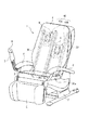
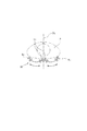
図1は本発明の一実施の形態に係るマッサージ機の全体斜視図であり、このマッサージ機1は、脚体2により支持された座ベース部3と、この座ベース部3の後側に接続された脊もたれ部4と、座ベース部3の前方下側に設けられたフットレスト5と、座ベース部3の左右両側に設けられた肘掛け部6と、一方の肘掛け部6に取り付けられたコントローラ支持部7とを備えている。前記コントローラ支持部7には、コントローラ8が脱着可能に取り付けられており、また脊もたれ部4は座ベース部3に対してリクライニングが可能である。なお、本明細書において、前記脊もたれ部4の幅方向を「左右方向」、高さ方向を「上下方向」、奥行き方向を「前後方向」といい、また脊もたれ部4を正面から見て左側を「左側」、同じく右側を「右側」という。
Hereinafter, a massage machine according to an embodiment of the present invention will be described in detail with reference to the accompanying drawings. In each drawing, in order to make it easy to see a specific part or part, illustration of other parts may be omitted.
FIG. 1 is an overall perspective view of a massage machine according to an embodiment of the present invention. The massage machine 1 is connected to a seat base portion 3 supported by a leg 2 and a rear side of the seat base portion 3. Spine rest 4,
前記脊もたれ部4の内部には、「揉み」、「叩き」及び「振動」の各動作を単独で又は適宜組み合わせてすることができる施療子9を備えた施療駆動部10を含む機械本体ユニット40が内蔵されている。この機械本体ユニット40は、前記脊もたれ部4の中心線の左右それぞれに配設されており、左右一対の機械本体ユニット40a、40bは、当該脊もたれ部4の内部においてそれぞれ左右一対のガイド溝30aを有するガイドレール30に沿って昇降自在に設けられている。
Inside the spine 4 is a machine body unit including a
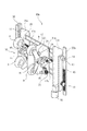
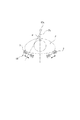
図2は、前記左右一対の機械本体ユニット40a、40bのうち左側の機械本体ユニット40aの斜視説明図であり、図3は、この機械本体ユニット40aの平面説明図である。機械本体ユニット40aは、互いに対向する左右の板状部材からなるフレーム11a、11bと、このフレーム11a、11bの上下において平行に配設されており、左右のフレーム11a、11bを連結する断面略コの字状のスライドレール12a、12bと、前記フレーム11a、11bに後述するネジ棒を介して左右方向に移動自在に支持された施療駆動部10とを備えている。前記左右一対のフレーム11a、11bの外側面には、前記ガイド溝30a内を走行するローラ13が配設されており、このローラ13はフレーム11a、11bに突設された軸14に回転自在に支持されている。ローラ13は、機械本体ユニット40aの上下左右4箇所に配置されている。4個のローラ13のうち、右下のローラ13は、その外周面に歯が形成されてピニオンを構成しており、このピニオンは前記ガイドレール30の後側部材30bの内周面に形成されたラック15と噛み合うように配置されている。そして、機械本体ユニット40aの右下に配設されているモータ16の回転を減速機構(図示せず)を介して前記ピニオンに伝達し、このピニオンを回転させることで、当該機械本体ユニット40aをガイドレール30に沿って昇降させている。
FIG. 2 is a perspective explanatory view of the left
前記施療駆動部10は、施療子(揉み玉)9を駆動させるモータや減速機構等が内蔵された駆動ユニット17と、この駆動ユニット17の左右の側壁17aから突出する揉み動作用の軸31(図3参照)に固定されたレバー18と、このレバー18の端部に配設され、前記施療子9を上下に支持したアーム19とで主に構成されている。本実施の形態において、前記駆動ユニット17内には当該駆動ユニット17の右側に配設された施療子9用に2個(揉み用モータと叩き用モータ)、左側に配設された施療子9用に2個、合計4個のモータ配設されている。揉み用モータの出力軸は、前記軸31に連結されており、叩き用モータの出力軸は、軸33に連結されている。また、各アーム19の後部側上部には、振動動作用のモータ24を内蔵したケーシング25が固設されている。そして、左右の施療子9は互いに独立して駆動可能であるとともに、各施療子9は、従来より知られている各種機構を用いて「揉み」、「叩き」及び「振動」の各動作を単独で又は適宜組み合わせてすることができるようになっている。この場合、脊もたれ部の幅方向に合計4つの施療子が存在し、これら4つの施療子が互いに独立して駆動可能となるので、きめ細かなマッサージをすることができる。例えば、4つの施療子のうち外側2つに揉み動作をさせ、内側2つに叩き動作をさせたり、外側2つだけを駆動させ、内側2つを停止させたりする等種々のマッサージをすることができる。
The
本発明の特徴は、前記左右一対の施療駆動部10が、互いに独立して昇降自在であるとともに、脊もたれ部4の左右方向に互いに独立して移動自在であることである。詳述すると、前記スライドレール12a、12bの間には当該スライドレール12a、12bと平行にネジ棒20が配置されており、このネジ棒20の両端は前記左右のフレーム11a、11bにそれぞれ固定されている(図3参照)。また、駆動ユニット17の後壁の外面には、外周がウォーム歯車構造となっているナット体21を回転自在に支持するケーシング22が配設されている。前記ナット体21はネジ棒20に螺合されており、また駆動ユニット17の後壁の外面であって前記ケーシング22の下方に配置されたモータ23の出力軸には、前記ナット体21のウォーム歯車と噛み合うウォーム32が設けられている。そして、モータ23を正転又は逆転させると、この回転がウォーム32を介してナット体21のウォーム歯車に伝達され、当該ナット体21を回転させる。このナット体21は、フレーム11a、11bに固定されたネジ棒20と螺合しており、ナット体21が回転すると、当該ナット体21はネジ棒20に沿って左右に移動する。これにより、前記ナット体21に固定されている施療駆動部10は、左右に移動することができる。
The feature of the present invention is that the pair of left and right
このように、本発明のマッサージ機では、脊もたれ部の中心線の左右それぞれに配設された施療駆動部10が、互いに独立して昇降自在であるとともに脊もたれ部4の左右方向にも移動自在であるので、従来のマッサージ機よりも広い範囲、すなわち被施療者の首から腰に至る範囲のほぼすべてを施療することができる。また、施療駆動部10の上下と左右の移動は別個に行うこともできるが、これらを同時に行うと、被施療者の身体を斜めにマッサージしたり、波線を描くようにマッサージしたりする等、従来にはないマッサージ動作を実現することができる。これにより、被施療者に対するマッサージ効果を一層高めることができる。
As described above, in the massage machine according to the present invention, the
左右一対の施療駆動部10は、同じ動作速度で駆動させることもできるが、右半身と左半身とで異なるマッサージを行って一層マッサージ効果を高めるために、互いに異なる動作速度で駆動させることもできる。また、左右で同じ施療を行うこともできるが、同じく右半身と左半身とで異なるマッサージを行って一層マッサージ効果を高めるために、互いに異なる施療を行うこともできる。
The pair of left and right
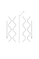
図4〜8は、本発明のマッサージ機における施療駆動部の動作パターンのいくつかの例を示している。図4は脊もたれ部4の中心線CLの左右の施療駆動部を同期させて下降させつつ、揉みマッサージを行う動作パターンを示し、図5は左側の施療駆動部を最上部から下降させる一方において右側の施療駆動部を最下部から上昇させつつ、揉みマッサージを行う動作パターンを示している。また、図6は左右の施療駆動部の動作速度を変えた動作パターンであって、右側の動作速度を左側の略2倍にして揉みマッサージを行う動作パターンを示している。図7は左右の施療駆動部のスタート位置を変えた動作パターンであって、左側の施療駆動部は最上部から、右側の施療駆動部は中央やや上方からスタートして揉みマッサージを行う動作パターンを示している。さらに、図8は左右で逆位相の揉みマッサージ(一方の施療子が近づくとき、他方の施療子が離れる揉みマッサージ)を行う動作パターンを示している。この図4〜8に示される動作パターンにおいて、「揉み」に「叩き」及び/又は「振動」を追加することもできる。さらに、図示した例では、分かり易くするために施療駆動部を昇降だけさせているが、昇降と同時に左右に移動させることで、被施療者の身体を斜めにマッサージしたり、波線を描くようにマッサージしたりする等さらに変化に富んだマッサージをすることができる。 4 to 8 show some examples of operation patterns of the treatment driving unit in the massage machine of the present invention. FIG. 4 shows an operation pattern in which massage treatment is performed while the left and right treatment drive parts of the center line CL of the spine 4 are lowered synchronously, and FIG. 5 shows the left treatment drive part being lowered from the top. The operation pattern which performs massage massage while raising the right treatment drive part from the lowest part is shown. FIG. 6 shows an operation pattern in which the operation speeds of the left and right treatment drive units are changed, and the operation speed on the right side is approximately doubled on the left side and massage massage is performed. FIG. 7 shows an operation pattern in which the start positions of the left and right treatment drive units are changed. The left treatment drive unit starts from the top, and the right treatment drive unit starts from the center and slightly above. Show. Further, FIG. 8 shows an operation pattern for performing an itching massage in opposite phases on the left and right (a massage massage in which the other treatment element leaves when one treatment element approaches). In the operation patterns shown in FIGS. 4 to 8, “striking” and / or “vibration” can be added to the “grudge”. Furthermore, in the illustrated example, the treatment drive unit is only raised and lowered for easy understanding, but by moving left and right at the same time as raising and lowering, the body of the patient is massaged diagonally or wavy lines are drawn You can have a variety of massages such as massage.
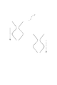
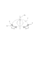
図9〜11は、本発明のマッサージ機における施療駆動部の他の例の動作パターンを説明する図である。図2〜3に示される施療駆動部10は、上方から見て直線状に左右方向に移動しているが、図9に示される例では、上方から見て円弧状(被施療者側が凹となる円弧)に左右方向に移動するように構成されている。この例では、左右の施療駆動部10における施療子9が被施療者Pの前後方向の中心線Pcに関して外側に移動したとき、各施療駆動部10における外側の施療子9oは、被施療者Pに対し内側方向(前記中心線Pcに向かう方向)にマッサージをすることができる。一方、左右の施療駆動部10における施療子9が被施療者Pの前後方向の中心線Pcに関して内側に移動したとき、各施療駆動部10における内側の施療子9iは、被施療者Pに対し外側方向(前記中心線Pcから離れる方向)にマッサージをすることができる。このように、被施療者Pの背中の面に対し斜め方向のマッサージをすることができ、従来にないマッサージ感を得ることができる。
9-11 is a figure explaining the operation | movement pattern of the other example of the treatment drive part in the massage machine of this invention. The
図10に示される例では、施療駆動部10の中心線10cが、被施療者Pの前後方向の中心線Pcに対して角度αをなすように傾斜している。このため、被施療者Pの背中面だけでなく、わき腹等の側面をもマッサージすることができる。図11に示される例では、図10の例における施療駆動部10を上方から見て円弧状に左右方向に移動させている。この場合、図10に示される例よりも、さらに被施療者Pの側面側に回り込んでマッサージをすることができる。
In the example shown in FIG. 10, the
なお、本発明において、施療駆動部を昇降させる機構、及び左右に移動させる機構は、特に限定されるものではなく、ラックとピニオンを用いて昇降させる代わりに、例えば公知のネジ棒方式を採用することができ、一方、ネジ棒とナット体を用いて左右に移動させる機構に代えて、例えばラック・ピニオン方式を採用することができる。 In the present invention, the mechanism for raising and lowering the treatment drive unit and the mechanism for moving it to the left and right are not particularly limited, and instead of raising and lowering using a rack and pinion, for example, a known screw rod system is adopted. On the other hand, a rack and pinion system, for example, can be adopted instead of the mechanism that moves left and right using a screw rod and a nut body.
1マッサージ機
3座ベース部
4脊もたれ部
9施療子
10施療駆動部
30ガイドレール
1 massage machine 3 seat base 4
Claims (7)
前記施療駆動部が、前記脊もたれ部の中心線の左右それぞれに配設されており、且つ
左右一対の施療駆動部が、互いに独立して昇降自在であるとともに脊もたれ部の左右方向に移動自在であることを特徴とするマッサージ機。 A massage having a seat base portion and a spine portion connected to the rear portion of the seat base portion, and a treatment drive portion for treating a user being disposed in the spine portion so as to be movable up and down Machine,
The treatment drive unit is arranged on each of the left and right of the center line of the spine, and the pair of left and right treatment drive units can be moved up and down independently of each other and movable in the left and right direction of the spine This is a massage machine.
Priority Applications (1)
| Application Number | Priority Date | Filing Date | Title |
|---|---|---|---|
| JP2005218143A JP2007029481A (en) | 2005-07-28 | 2005-07-28 | Massage machine |
Applications Claiming Priority (1)
| Application Number | Priority Date | Filing Date | Title |
|---|---|---|---|
| JP2005218143A JP2007029481A (en) | 2005-07-28 | 2005-07-28 | Massage machine |
Publications (1)
| Publication Number | Publication Date |
|---|---|
| JP2007029481A true JP2007029481A (en) | 2007-02-08 |
Family
ID=37789430
Family Applications (1)
| Application Number | Title | Priority Date | Filing Date |
|---|---|---|---|
| JP2005218143A Pending JP2007029481A (en) | 2005-07-28 | 2005-07-28 | Massage machine |
Country Status (1)
| Country | Link |
|---|---|
| JP (1) | JP2007029481A (en) |
Cited By (13)
| Publication number | Priority date | Publication date | Assignee | Title |
|---|---|---|---|---|
| JP2008295888A (en) * | 2007-06-01 | 2008-12-11 | Fuji Iryoki:Kk | Massage ball |
| JP2008302059A (en) * | 2007-06-08 | 2008-12-18 | Kyushu Hitachi Maxell Ltd | Massage machine |
| JP2009090005A (en) * | 2007-10-11 | 2009-04-30 | Family Co Ltd | Massage unit and massage machine provided with it |
| WO2009125605A1 (en) * | 2008-04-11 | 2009-10-15 | ファミリー株式会社 | Massage mechanism |
| JP2012055722A (en) * | 2011-12-16 | 2012-03-22 | Fuji Iryoki:Kk | Massage machine |
| JP2014008289A (en) * | 2012-06-29 | 2014-01-20 | Hitachi Maxell Ltd | Massage machine |
| CN105030513A (en) * | 2015-09-22 | 2015-11-11 | 苏州春天印象健身器材有限公司 | Machine core of massage armchair |
| JP2018047293A (en) * | 2017-11-27 | 2018-03-29 | マクセルホールディングス株式会社 | Massage machine |
| CN109124977A (en) * | 2018-08-16 | 2019-01-04 | 浙江艾荣达健康科技有限公司 | A kind of abdominal massaging chair |
| CN109718070A (en) * | 2017-10-27 | 2019-05-07 | 富士医疗器股份有限公司 | Massage unit and massager |
| JP2019076777A (en) * | 2018-04-12 | 2019-05-23 | 株式会社フジ医療器 | Massage machine |
| JP2019122881A (en) * | 2014-10-24 | 2019-07-25 | ファミリーイナダ株式会社 | Massage machine |
| KR20220040845A (en) | 2020-09-24 | 2022-03-31 | 주식회사 바디프랜드 | Massage Instrument Having Separated Massage Modules |
Citations (8)
| Publication number | Priority date | Publication date | Assignee | Title |
|---|---|---|---|---|
| JPS56125046A (en) * | 1980-03-05 | 1981-10-01 | Matsushita Electric Works Ltd | Massager |
| JPH09262264A (en) * | 1996-03-27 | 1997-10-07 | Family Kk | Massage machine |
| JP2000135261A (en) * | 1998-11-02 | 2000-05-16 | Family Kk | Massager |
| JP2001231829A (en) * | 2000-02-22 | 2001-08-28 | Family Kk | Massager |
| US6443917B1 (en) * | 1997-06-17 | 2002-09-03 | Eurokeyton, S. A. | Massaging device for a rest armchair |
| JP2002282318A (en) * | 2001-03-26 | 2002-10-02 | Family Kk | Massager |
| JP2003144505A (en) * | 2001-11-12 | 2003-05-20 | Marutaka Co Ltd | Chair type massage machine |
| JP2003275264A (en) * | 2002-03-25 | 2003-09-30 | Marutaka Co Ltd | Chair-type massaging machine |
-
2005
- 2005-07-28 JP JP2005218143A patent/JP2007029481A/en active Pending
Patent Citations (8)
| Publication number | Priority date | Publication date | Assignee | Title |
|---|---|---|---|---|
| JPS56125046A (en) * | 1980-03-05 | 1981-10-01 | Matsushita Electric Works Ltd | Massager |
| JPH09262264A (en) * | 1996-03-27 | 1997-10-07 | Family Kk | Massage machine |
| US6443917B1 (en) * | 1997-06-17 | 2002-09-03 | Eurokeyton, S. A. | Massaging device for a rest armchair |
| JP2000135261A (en) * | 1998-11-02 | 2000-05-16 | Family Kk | Massager |
| JP2001231829A (en) * | 2000-02-22 | 2001-08-28 | Family Kk | Massager |
| JP2002282318A (en) * | 2001-03-26 | 2002-10-02 | Family Kk | Massager |
| JP2003144505A (en) * | 2001-11-12 | 2003-05-20 | Marutaka Co Ltd | Chair type massage machine |
| JP2003275264A (en) * | 2002-03-25 | 2003-09-30 | Marutaka Co Ltd | Chair-type massaging machine |
Cited By (24)
| Publication number | Priority date | Publication date | Assignee | Title |
|---|---|---|---|---|
| JP2008295888A (en) * | 2007-06-01 | 2008-12-11 | Fuji Iryoki:Kk | Massage ball |
| JP2008302059A (en) * | 2007-06-08 | 2008-12-18 | Kyushu Hitachi Maxell Ltd | Massage machine |
| JP2009090005A (en) * | 2007-10-11 | 2009-04-30 | Family Co Ltd | Massage unit and massage machine provided with it |
| WO2009125605A1 (en) * | 2008-04-11 | 2009-10-15 | ファミリー株式会社 | Massage mechanism |
| JP2009254408A (en) * | 2008-04-11 | 2009-11-05 | Family Co Ltd | Massage mechanism |
| CN101959489A (en) * | 2008-04-11 | 2011-01-26 | 发美利株式会社 | Massage mechanism |
| KR101146851B1 (en) * | 2008-04-11 | 2012-05-16 | 패밀리 가부시키가이샤 | Massage mechanism |
| JP2012055722A (en) * | 2011-12-16 | 2012-03-22 | Fuji Iryoki:Kk | Massage machine |
| JP2014008289A (en) * | 2012-06-29 | 2014-01-20 | Hitachi Maxell Ltd | Massage machine |
| JP7053044B2 (en) | 2014-10-24 | 2022-04-12 | ファミリーイナダ株式会社 | Massage machine |
| JP7053072B2 (en) | 2014-10-24 | 2022-04-12 | ファミリーイナダ株式会社 | Massage machine |
| JP2019122881A (en) * | 2014-10-24 | 2019-07-25 | ファミリーイナダ株式会社 | Massage machine |
| JP2021065756A (en) * | 2014-10-24 | 2021-04-30 | ファミリーイナダ株式会社 | Massage machine |
| JP2022179657A (en) * | 2014-10-24 | 2022-12-02 | ファミリーイナダ株式会社 | Massage machine |
| JP2022058808A (en) * | 2014-10-24 | 2022-04-12 | ファミリーイナダ株式会社 | Massage machine |
| CN105030513A (en) * | 2015-09-22 | 2015-11-11 | 苏州春天印象健身器材有限公司 | Machine core of massage armchair |
| CN109718070B (en) * | 2017-10-27 | 2022-12-02 | 富士医疗器股份有限公司 | Massage unit and massage machine |
| CN109718070A (en) * | 2017-10-27 | 2019-05-07 | 富士医疗器股份有限公司 | Massage unit and massager |
| JP2018047293A (en) * | 2017-11-27 | 2018-03-29 | マクセルホールディングス株式会社 | Massage machine |
| JP2019076777A (en) * | 2018-04-12 | 2019-05-23 | 株式会社フジ医療器 | Massage machine |
| CN109124977A (en) * | 2018-08-16 | 2019-01-04 | 浙江艾荣达健康科技有限公司 | A kind of abdominal massaging chair |
| CN109124977B (en) * | 2018-08-16 | 2023-06-20 | 浙江荣泰健康电器有限公司 | Abdomen massage chair |
| KR20220040845A (en) | 2020-09-24 | 2022-03-31 | 주식회사 바디프랜드 | Massage Instrument Having Separated Massage Modules |
| KR20230002156A (en) | 2020-09-24 | 2023-01-05 | 주식회사 바디프랜드 | Massage Instrument Having Separated Massage Modules |
Similar Documents
| Publication | Publication Date | Title |
|---|---|---|
| JP2007029481A (en) | Massage machine | |
| JP3113057U (en) | Massage device | |
| JP6238619B2 (en) | Massage device and chair type massage machine equipped with this massage device | |
| JP7072701B2 (en) | Massage machine | |
| JP2012217750A (en) | Massage machine | |
| JP5766507B2 (en) | Massage mechanism and massage machine equipped with this massage mechanism | |
| JPH09262264A (en) | Massage machine | |
| JP5599133B2 (en) | Massage machine | |
| JP2008302059A (en) | Massage machine | |
| JP2007014467A (en) | Massage mechanism of chair type massage machine | |
| JP2012135656A (en) | Massage machine | |
| JP2003144505A (en) | Chair type massage machine | |
| JP2007007005A (en) | Massage machine | |
| JP4710759B2 (en) | Massage machine | |
| JP7121998B2 (en) | chair massage machine | |
| JP2015077370A (en) | Massage unit | |
| JP2014094060A (en) | Massage mechanism and massage machine including massage mechanism | |
| CN106618985A (en) | Portable fitness appliance | |
| JP6750884B2 (en) | Massage device | |
| CN106618989A (en) | Waist and hip massage device | |
| JP4679983B2 (en) | Massage mechanism of chair type massage machine | |
| CN106619002A (en) | Portable body building apparatus | |
| JP5268560B2 (en) | Chair massage machine | |
| JP2003205007A (en) | Chair with foot massage roller | |
| JP2003070859A (en) | Armchair type massaging machine with built-in vibrator |
Legal Events
| Date | Code | Title | Description |
|---|---|---|---|
| A621 | Written request for application examination |
Free format text: JAPANESE INTERMEDIATE CODE: A621 Effective date: 20071210 |
|
| A977 | Report on retrieval |
Free format text: JAPANESE INTERMEDIATE CODE: A971007 Effective date: 20100210 |
|
| A131 | Notification of reasons for refusal |
Free format text: JAPANESE INTERMEDIATE CODE: A131 Effective date: 20100223 |
|
| A521 | Written amendment |
Free format text: JAPANESE INTERMEDIATE CODE: A523 Effective date: 20100409 |
|
| RD04 | Notification of resignation of power of attorney |
Free format text: JAPANESE INTERMEDIATE CODE: A7424 Effective date: 20100412 |
|
| A02 | Decision of refusal |
Free format text: JAPANESE INTERMEDIATE CODE: A02 Effective date: 20101018 |