JP2007319002A - Algae-treating ship and algae-treating system - Google Patents
Algae-treating ship and algae-treating system Download PDFInfo
- Publication number
- JP2007319002A JP2007319002A JP2006149094A JP2006149094A JP2007319002A JP 2007319002 A JP2007319002 A JP 2007319002A JP 2006149094 A JP2006149094 A JP 2006149094A JP 2006149094 A JP2006149094 A JP 2006149094A JP 2007319002 A JP2007319002 A JP 2007319002A
- Authority
- JP
- Japan
- Prior art keywords
- algae
- water
- treatment
- ship
- discharge
- Prior art date
- Legal status (The legal status is an assumption and is not a legal conclusion. Google has not performed a legal analysis and makes no representation as to the accuracy of the status listed.)
- Pending
Links
Images


Abstract
Description
本発明は、例えば、湖沼や貯水池、ダムなどにおいて発生するアオコと呼ばれる藻類の大増殖および拡散を防止するために用いられる藻類処理船に関する。 The present invention relates to an algae treatment ship used for preventing the large growth and spread of algae called aoko that occur in lakes, reservoirs, dams, and the like.
近年、富栄養化の原因によって,各地の湖沼、貯水池、ダム、溜池、水路、あるいは貯水槽等において、アオコと呼ばれる藍藻類の大量発生が起こり、悪臭の発生、景観の悪化、浄水場の浄水プロセスへの障害などが発生するなどの問題を引き起こしている。 In recent years, due to eutrophication, large numbers of blue-green algae called blue-green algae have occurred in various lakes, reservoirs, dams, reservoirs, waterways, or water tanks, etc., causing bad odors, landscape deterioration, and purification of water purification plants It causes problems such as process failures.
現在、この対策として曝気循環(全層曝気/表層曝気/深水曝気)、物理的制御(布/遠心分離/加圧浮上/マイクロストレーナ)、選択放流(表層放流/任意層放流)、浚渫・低質処理(渫/干し上げ/低泥除去)、河川流入対策(化学的抑制/副ダム/浄化施設の設置)、植物浄化/流路転換、浄化用水導入、噴水などが行われている。 Currently, as a countermeasure, aeration circulation (all layer aeration / surface aeration / deep water aeration), physical control (cloth / centrifugation / pressurization / microstrainer), selective discharge (surface discharge / arbitrary layer discharge), dredging / low quality Treatment (dripping / drying / removing low mud), river inflow countermeasures (chemical restraint / deputy dam / purification facilities), plant purification / flow channel conversion, purification water introduction, fountain, etc.
例えば、曝気循環や選択放流においては、その効果が曖昧であったり、装置コストや処理コストが高いなどの問題があり、物理的制御においては確実にアオコは除去されるものの、藻類を陸上または船上に取り上げるためにポンプの動力費や人件費が発生するだけでなく、取り出されたアオコは産業廃棄物となるため莫大な処分費が発生してしまうなどの問題が残されている。 For example, in aeration circulation and selective discharge, there are problems such as vague effects and high equipment costs and processing costs. In addition to the power costs and labor costs of the pumps that are taken up, there are still problems such as the huge amount of disposal costs because the picked up sea bream becomes industrial waste.
一方、水中の殺菌方法として、被処理水中に浸漬された電極間にパルス高電圧を印加して行うパルス放電法が知られている。水中でのパルス放電では、放電路付近に紫外線や衝撃波、ラジカルが発生する。この方法は、薬品を使用しない、瞬時に処理ができる、ランニングコストが安い、耐性菌が発生しない、処理水の水温が上昇しないなどの特徴を持つ。 On the other hand, as a sterilization method in water, a pulse discharge method is known in which a pulse high voltage is applied between electrodes immersed in water to be treated. In pulse discharge in water, ultraviolet rays, shock waves, and radicals are generated near the discharge path. This method has features such as no use of chemicals, instant treatment, low running costs, no generation of resistant bacteria, and no increase in the temperature of treated water.
放電路付近にアオコが存在する場合には、発生した衝撃波と高電界により細胞内の気泡が破壊されるためアオコの沈降が起こる。気泡の破壊だけでなく、電界強度の高い領域においては細胞内部も一部破壊される場合があり、生命活動維持できずにアオコが死滅する。パルス放電式処理では発生した衝撃圧力は瞬間的であるため、放電路およびその付近の水はほとんど移動せず、放電による新たな流れが発生しない。このため水流がない水域での処理後のアオコは垂直に沈降し、処理自身による藻類の拡散が起こらない。処理前後のアオコは大きな比重差がないために数分から数十時間で沈降する。沈降したアオコはやがて低水温と日照量の少なさのため光合成を行うことができず、休眠状態となり増殖できなくなる。例えば、文献1には水中パルス放電を用いてアオコを沈降処理する技術が開示されている。 In the case where there is a watermelon near the discharge path, the bubbles inside the cell are destroyed by the generated shock wave and high electric field, so that the watermelon settles down. In addition to the destruction of bubbles, the inside of the cell may be partially destroyed in the region where the electric field strength is high, and the aiko will die without being able to maintain life activity. In the pulse discharge type treatment, the generated impact pressure is instantaneous, so the water in the discharge path and the vicinity thereof hardly moves, and a new flow due to discharge does not occur. For this reason, sea cucumbers after treatment in a water area where there is no water flow will sink vertically, and algae will not diffuse due to the treatment itself. The sea cucumber before and after treatment settles in several minutes to several tens of hours because there is no large specific gravity difference. The settled sea cucumber will eventually be unable to carry out photosynthesis due to the low water temperature and the low amount of sunlight, and will become dormant and unable to multiply. For example, Document 1 discloses a technique for precipitating aquatic plants using underwater pulse discharge.
アオコの発生の原因となる藻類は、水中の栄養素、温度、日照量などの条件が重なった時に繁殖する。湖沼のような滞留水域では、季節ごとに深さ方向において所定の温度分布ができる。夏期には水面下0〜15mの範囲において温度が急激に変化する温度躍層が形成され、このような温度躍層より上の領域でアオコが成長・増殖すると考えられている。発生したアオコは浮上して水面近くを浮遊するが、浮遊したアオコは水流や湖面上を吹く風に乗り移動するために湖面を移動し、岸やワンド、構造物付近などの水の停留しやすい部分に集まる。湖沼のアオコの除去/増殖防止を行うには、湖沼の中央部だけでなく、移動しているアオコや停留しているアオコも対象としなければならない。 Algae that cause the occurrence of blue sea breams breed when conditions such as nutrients in water, temperature, and amount of sunlight overlap. In a stagnant water area such as a lake, a predetermined temperature distribution is created in the depth direction for each season. In summer, a temperature climatic layer is formed in which the temperature changes abruptly in the range of 0 to 15 m below the surface of the water, and it is thought that sea lions grow and proliferate in the region above such a temperature climatic layer. The generated sea bream rises and floats near the surface of the water, but the floating sea bream moves on the surface of the lake in order to ride on the water current and the wind blowing on the surface of the lake, and it is easy to stop water on the shore, wand, structure, etc. Gather in part. In order to remove / prevent the water in the lake, not only the central part of the lake, but also the moving and parked aquatic must be targeted.
本発明は、前記事情に鑑みてなされたもので、従来の藻類処理に関する問題を解消し、藻類を効率よく収集しかつ処理する藻類処理船を提供することを目的とする。 The present invention has been made in view of the above circumstances, and an object of the present invention is to provide an algal treatment ship that solves the problems related to conventional algae treatment and efficiently collects and treats algae.
前記目的を達成するために、請求項1に記載の藻類処理船は、水域を航行可能な処理船本体と、該処理船本体に搭載され、藻類の浮力を失わせる不活化装置と、該処理船本体に搭載され、水域中の藻類を前記不活化装置に導く収集手段とを有することを特徴とする。 In order to achieve the object, an algal treatment ship according to claim 1 is provided with a treatment ship main body capable of navigating a water area, an inactivation device mounted on the treatment ship main body and losing alga buoyancy, and the treatment It is mounted on a ship body and has a collecting means for guiding algae in the water area to the inactivation device.
請求項1に記載発明によれば、処理船本体を藻類が発生している水域に航行し、水域中の藻類を収集して不活化装置に導き、藻類の浮力を失わせて放出することにより、藻類を沈降させてその増殖を防止する。 According to the invention described in claim 1, by navigating the treatment ship main body to the water area where algae are generated, collecting the algae in the water area, guiding them to an inactivation device, and releasing the algae by losing its buoyancy , Sediment the algae and prevent their growth.
請求項2に記載の藻類処理船は、請求項1に記載された発明において、前記収集手段が前記処理船本体から分離できることを特徴とする。
請求項2に記載発明によれば、収集手段を処理船本体から分離して操作することで、浅瀬や狭い水域の藻類が不活化装置に導かれて処理可能となる。
The algae treatment ship according to claim 2 is characterized in that, in the invention according to claim 1, the collection means can be separated from the main body of the treatment ship.
According to the second aspect of the present invention, by operating the collecting means separately from the main body of the processing vessel, the algae in the shallow water or the narrow water area is guided to the inactivation device and can be processed.
請求項3に記載の藻類処理船は、請求項1又は請求項2に記載の発明において、藻類沈降処理後の処理水の循環手段を有し、複数回の沈降処理ができることを特徴とする。
請求項3に記載発明によれば、藻類沈降処理後の処理水を循環させることで、複数回の沈降処理が可能となり、多量の藻類を含む処理水も順次遅効処理することができる。
The algae treatment ship according to claim 3 is characterized in that, in the invention according to claim 1 or claim 2, the algae treatment ship has means for circulating the treated water after the algae sedimentation treatment and can perform sedimentation treatment a plurality of times.
According to the third aspect of the present invention, by circulating the treated water after the algal sedimentation treatment, the sedimentation treatment can be performed a plurality of times, and the treated water containing a large amount of algae can be sequentially delayed.
請求項4に記載の藻類処理船は、請求項3に記載の発明において、前記循環手段は沈降槽を有し、藻類を沈降させながら処理水を循環させることを特徴とする。
請求項4に記載発明によれば、処理水中の藻類は、処理水が循環する途中で沈降槽において沈降し、分離される。
According to a fourth aspect of the present invention, there is provided the algae treatment ship according to the third aspect of the invention, wherein the circulation means has a sedimentation tank and circulates the treated water while allowing the algae to settle.
According to the invention described in claim 4, the algae in the treated water is settled and separated in the settling tank while the treated water is circulating.
請求項5に記載の藻類処理船は、請求項4に記載の発明において、前記沈降槽は、前記処理船本体に搭載した沈降槽形成手段により該処理船本体の周囲の水域に形成されることを特徴とする。
請求項5に記載発明によれば、沈降槽は、処理船本体に搭載した沈降槽形成手段により該処理船本体の周囲の水域に形成されるので、処理船自体はコンパクトになる。
The algae treatment ship according to claim 5 is the invention according to claim 4, wherein the sedimentation tank is formed in a water area around the main body of the treatment ship by a sedimentation tank forming means mounted on the main body of the treatment ship. It is characterized by.
According to the fifth aspect of the present invention, the sedimentation tank is formed in the water area around the main body of the processing ship by the sedimentation tank forming means mounted on the main body of the processing ship.
請求項6に記載の藻類処理システムは、藻類の浮力を失わせる不活化装置を有する処理船と、水域中の藻類を前記不活化装置に導く外部誘導手段とを有することを特徴とする。
請求項6に記載の藻類処理システムは、水域中の藻類は外部の誘導手段によって不活化装置に導かれ、効率良く処理される。
The algae treatment system according to claim 6 includes a treatment ship having an inactivation device for losing the buoyancy of algae, and an external guiding means for guiding the algae in the water area to the inactivation device.
In the algae processing system according to the sixth aspect, the algae in the water area are guided to the inactivation device by an external guiding means and are efficiently processed.
請求項1ないし請求項6に記載の発明によれば、藻類を効率よく収集しかつ処理することができる。 According to invention of Claim 1 thru | or 6, algae can be collected and processed efficiently.
以下、図面に記載の発明の実施形態に基づいて、この発明をより具体的に説明する。
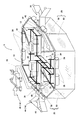
図1および図2は本発明の実施の形態の藻類処理船(以下、処理船)Sの全体の構成を示す図である。この処理船Sは、湖沼等の所定の水域において移動可能な処理船本体10と、これに搭載された藻類処理装置12とを備えている。藻類処理装置12は、水面付近に浮遊するアオコ等の藻類を収集して藻類処理装置12に導く収集装置14、収集した藻類の気泡を破壊して浮力を失わせる不活化装置16、および処理船本体10の周囲に設置されて藻類を沈降させるための沈降槽18を形成するための沈降槽形成手段20とを備えている。
Hereinafter, the present invention will be described more specifically based on embodiments of the invention described in the drawings.
FIG. 1 and FIG. 2 are diagrams showing an overall configuration of an algae processing ship (hereinafter, processing ship) S according to an embodiment of the present invention. The treatment ship S includes a treatment ship
処理船本体10は、藻類処理装置12を搭載する能力と構造を備えていれば、適宜な形式が採用できる。図に示すのは、主板22とそれから横に延びる連結板24によって主板22に結合された副板26と、各部に設置されたフロート28を備えた簡易な形式の双胴船である。主板22には、藻類処理装置12の要部が搭載され、その下部には不活化装置16が設置されている。なお、スクリュー、エンジン、運転室等の駆動装置は図示を省略している。双胴船は水深の浅い場所へも移動ができ、船体の真下中央に不活化装置16を設置できる利点が有る。もちろん、他の形式の船でもよいし、他の船に牽引されて移動する形式でも良い。
If the processing ship
不活化装置16は、この実施の形態ではパルス放電処理装置であり、処理船本体10の船首から船尾に掛けて延びるダクト30と、ダクト30内に配置された(高圧)電極32と、電極32と接地電極(ダクト30)間に高電圧パルスを印加してパルス放電を起こすためのパルス電源および放電盤を備えた放電装置34とを備えている。ダクト30の先端は収集装置14に連絡し、後端は排出口36に連絡している。
The
ダクト30の前後部には送水用の2台のポンプ38a,38bと、沈降槽18に開口する流入口40と流出口42とが設けられている。この例では、流入口40と流出口42はそれぞれ左右に設けられているが、いずれか一方のみでもよい。後段側のポンプ38bは、後述するように循環流を形成するために用いられるもので、前段側のポンプ38aより排水量を多く設定する。2つのポンプ38a,38bの排水量の差の分が循環量となる。循環用の流入口40と流出口42は、それぞれ水面と同じレベルに開口しており、ダクト30中に浮上する藻類は流出口42から排出されやすく、循環用入口から取り入れやすくなっている。ダクト30の断面形状は丸型、角型などいずれでもよい。不活化装置16として、パルス放電を用いる場合には、電界強度の均一性が必要であり、丸型が望ましい。図1には排出口36が水面と平行に示されているが、湖底方向へ向けてもよい。この場合、処理後の藻類の沈降を容易にするだけでなく、低水温領域へ移動することで増殖を抑えられる。
Two
図3はダクト30内に配置された放電用の電極32を示す図である。(a)は棒または針状の電極32であり、(b)は線電極32である。(a)の場合、放電領域を広く、かつ、放電を起こしやすくするために、多芯電線やワイヤーを用いて、先端をブラシ状にするのが望ましい。いずれの場合もダクト30壁面へ向けて放射状に放電路が進展する。電極32を容易に交換するためにダクト30へはフランジを用いて固定するのが望ましい。また複数の電極32を配置する場合には、互いの電界が影響しないように、電極32間に金属のメッシュを配置するのが良い。パルス放電の場合、アーク放電およびストリーマ放電のいずれでも可能だが、ストリーマ放電が望ましい。図示するように、安全のために処理船本体10を接地電位とすることが望ましく、放電領域を広くするために電極には正極性の電圧を印加することが望ましい。
FIG. 3 is a diagram showing a
上記のように、アオコの処理のためのパルス放電方式には、アーク放電とストリーマ放電とがある。アーク放電の場合は、アーク点から発生した強力な衝撃が主な作用となる。衝撃波は水中を伝播するために絶縁破壊に必要な電圧が電極印加できればよく、極めて高い電圧は必要ない。ストリーマ放電を発生させるためには高い電圧が必要となるが、あまりに高い電圧では部品や装置における費用や大きさにおける絶縁対策が問題となるため、実用的な電圧が存在する。パルス放電の様式としてアーク放電を用いる場合には電極への印加電圧は1kVから100kVがよく、好ましくは5kVから30kVがよい。ストリーマ放電を用いる場合には10kVから300kVがよく、好ましくは50kVから180kVがよい。処理船に積載されているパルス電源はストリーマ放電範囲での電圧調整が可能となっている。 As described above, there are arc discharge and streamer discharge in the pulse discharge method for the treatment of the water. In the case of arc discharge, the main effect is a strong impact generated from the arc point. Since the shock wave propagates in water, it is sufficient that a voltage necessary for dielectric breakdown can be applied to the electrode, and an extremely high voltage is not necessary. In order to generate streamer discharge, a high voltage is required. However, if the voltage is too high, there is a problem of insulation measures in terms of cost and size in parts and devices, and there is a practical voltage. When arc discharge is used as the mode of pulse discharge, the voltage applied to the electrode is preferably 1 kV to 100 kV, and preferably 5 kV to 30 kV. When streamer discharge is used, the voltage is 10 kV to 300 kV, preferably 50 kV to 180 kV. The pulse power supply mounted on the processing vessel can adjust the voltage in the streamer discharge range.
予備的な実験として、貯水池より採取したアオコ(主にミクロキスティス)を12Lの金属容器に入れ、金属容器中央に電極を配置して、パルス放電処理を行った。パルス電圧は156kV、放電回数1〜6回である。(a)放電処理後のアオコの色変化を調べるため、未処理および放電6回後のアオコを写真撮影し、その変化を観察した。(b)放電処理によるアオコの沈降性の変化を調べるため、未処理および放電1, 3, 6回後のアオコをそれぞれ50ccの容器に移し、すべての容器を同時に攪拌後に静置して、15時間後の沈降状態を写真撮影して沈降性を比較した。 As a preliminary experiment, Aoko (mainly microkistis) collected from a reservoir was placed in a 12 L metal container, and an electrode was placed in the center of the metal container to perform a pulse discharge treatment. The pulse voltage is 156 kV and the number of discharges is 1 to 6 times. (A) In order to investigate the color change of the watermelon after the discharge treatment, photographs were taken of the watermelon that had not been treated and after discharge six times, and the change was observed. (b) In order to investigate the change in the sedimentation of the ako due to the discharge treatment, the ako after untreated and 1,3,6 discharges were transferred to 50cc containers, and all the containers were allowed to stand after stirring at the same time. The sedimentation state after time was photographed to compare sedimentation properties.
その結果、(a)未処理のアオコは黄緑色であったのに対し、放電6回後のアオコは深緑色に変化していた。これは気泡の破壊によりアオコの透過率/反射率が変化していたためと考えられる。1度の放電で、電極先端を中心とした放電領域のアオコはほぼ完全に反応する。このため、アオコには一度だけ放電を与えればよく、放電領域を重複させないことが有効であることが明らかとなった。
また、(b)放電数が増えるに従い、アオコの沈殿量が増加していた。放電6回ではほぼすべてのアオコが沈殿した。放電毎に攪拌を行って処理しているため、何度も放電を受けたアオコが存在するが、平均的には一回の放電で2Lを処理できることが明らかとなった。
As a result, (a) the untreated aoko was yellow-green, whereas the ako after six discharges changed to a dark green color. This is thought to be because the transmittance / reflectance of the sea bream changed due to the destruction of the bubbles. With a single discharge, the water in the discharge region centered on the electrode tip reacts almost completely. For this reason, it has been clarified that it is effective not to overlap the discharge areas, and it is necessary to discharge the aoko only once.
In addition, (b) as the number of discharges increased, the amount of aquatic precipitation increased. Almost all of the sea urchins were precipitated after 6 discharges. Since each discharge is agitated and processed, there are some sea cucumbers that have been discharged many times. On average, 2L can be processed with one discharge.
ストリーマ放電による処理の場合、ストリーマ放電領域の大きさは、電極先端を中心として直径0.1m〜0.3mの球状になる。処理ダクトの直径がこの大きさに近い場合は、電極先端から発生した放電チャネルがしばしば壁面に達し、ストリーマ放電からアーク放電に移行する。一度、アーク放電が発生すると、衝撃波を伴う大音響と、壁面および電極先端の蒸発のよる損傷が発生してしまう。アーク放電に移行させなためには電極先端とダクト壁面との間に十分な距離を保つことが望ましいが、放電領域に接触しないアオコは影響を受けなくなってしまうため、あまり長くならないようにしなければならない。上述の電圧範囲における放電領域の大きさを考えると、対象処理水の水質(電気伝導率)の変化に対応して、直径0.15mから0.5mの間ダクトが取り付けられるようになっている。 In the case of treatment by streamer discharge, the size of the streamer discharge region is a sphere having a diameter of 0.1 m to 0.3 m centering on the electrode tip. When the diameter of the processing duct is close to this size, the discharge channel generated from the electrode tip often reaches the wall surface and shifts from streamer discharge to arc discharge. Once the arc discharge is generated, a large sound accompanied by a shock wave and damage due to evaporation of the wall surface and the electrode tip are generated. It is desirable to maintain a sufficient distance between the electrode tip and the duct wall surface in order to avoid the transition to arc discharge. However, aquatic that does not contact the discharge area will not be affected, so it should not be too long. Don't be. Considering the size of the discharge region in the voltage range described above, a duct with a diameter of 0.15 m to 0.5 m is attached in accordance with the change in water quality (electrical conductivity) of the target treated water.
この処理船では、処理ダクトの流入口および流出口に堰板を取り付け、水面からの取り込み水深を制限できる。アオコが均一に分散しているような処理水においてはまず水深50cm程度までを取水するが、アオコが水面付近に集中しているような場合は、取り込み深さは20cm程から5cmにまで調整できるような構造となっている。 In this treatment ship, weir plates can be attached to the inlet and outlet of the treatment duct to limit the water depth taken from the water surface. In the treated water in which the water is uniformly dispersed, the water is first taken up to a depth of about 50 cm, but if the water is concentrated near the water surface, the uptake depth can be adjusted from about 20 cm to 5 cm. It has a structure like this.
上述のようにアーク放電への移行を避けるため、放電で発生する球状の放電領域である放電球がダクト壁面に到達しないようにするが、このためダクト壁面付近には反応しないアオコが流れてゆく。パルス放電装置を2台以上処理船に積載する場合、ダクト内をアオコ濃度が均一な層流で流れるとすると、1度放電を受けた処理水は、再び放電を受けることになり、処理効率が低下する。このため、ダクト内のスクリューは送水だけでなく、処理水の攪拌も行うことで効率的にアオコに放電を与え、かつ消費電力を低減させている。 As described above, in order to avoid the transition to arc discharge, the discharge sphere, which is a spherical discharge region generated by discharge, is prevented from reaching the duct wall surface. . When two or more pulse discharge devices are loaded on a treatment vessel, if the inside of the duct flows in a laminar flow with a uniform concentration, the treated water that has been discharged once will be discharged again, and the treatment efficiency will be improved. descend. For this reason, the screw in the duct not only feeds water but also stirs the treated water, thereby efficiently discharging the watermelon and reducing power consumption.
処理流量はダクト内にあるスクリューの性能によって決まるが、効率的な処理を行う時には流量と放電頻度(周波数)との間には適当な関係が存在する。流量が少ない場合は放電の頻度を上げても、球状の放電領域の重なりが増えるだけで効率が悪くなり、逆に流量が多い場合には、放電領域が間隔を空けて発生するため、効率の悪い処理となる。最も効率がよい処理の場合は、毎回の放電で発生した球状の放電領域が接する場合であり、その関係は式(1)のようになる。
v = R × f (1)
ここでv[m/sec]は流速、R[m]は放電領域の範囲(球の直径)、f[Hz]は放電頻度である。
The treatment flow rate is determined by the performance of the screw in the duct, but there is an appropriate relationship between the flow rate and the discharge frequency (frequency) when performing efficient treatment. If the flow rate is low, even if the frequency of discharge is increased, the efficiency will deteriorate due to an increase in the overlap of the spherical discharge areas. Conversely, if the flow rate is high, the discharge areas will be generated at intervals. It is a bad process. In the case of the most efficient process, a spherical discharge region generated by each discharge is in contact with each other, and the relationship is as shown in Expression (1).
v = R × f (1)
Here, v [m / sec] is a flow velocity, R [m] is a discharge area range (sphere diameter), and f [Hz] is a discharge frequency.
そこで、この処理船では(1)式の関係を満たすように運転が制御される。このときのパルス放電電源1台あたりの体積効率ηは、ダクト直径をDとして
η=(4/3×3.14×(R/2)3)/(3.14×(D/2)2×R) (3)
となる。例えば、R=0.1m、D=0.2mの場合には、η=16.7%となり、ひとつのダクトにパルス電源がn台ある場合の効率η’は
η’=(1−(1−η)n) (4)
になる。パルス電源が2台設置されている場合には、沈降層内を処理水が6回循環するように処理を行えば、90%以上のアオコが処理される。いずれのダクト直径でも、ダクト径の指定することで、処理率が90%以上になるように必要な沈降層の循環回数を満たすように制御が行われる。
Therefore, the operation of this processing ship is controlled so as to satisfy the relationship of the expression (1). The volumetric efficiency η per pulse discharge power supply at this time is η = (4/3 × 3.14 × (R / 2) 3 ) / (3.14 × (D / 2) 2 × R) where D is the duct diameter. 3)
It becomes. For example, when R = 0.1m and D = 0.2m, η = 16.7%, and the efficiency η ′ when there are n pulse power supplies in one duct is
η '= (1- (1-η) n ) (4)
become. When two pulse power sources are installed, if processing is performed so that the treated water circulates six times in the sedimentation layer, 90% or more of the sea cucumber is processed. Regardless of the duct diameter, by specifying the duct diameter, control is performed so as to satisfy the required number of sedimentation layer circulations so that the treatment rate is 90% or more.
処理ダクトには流量計が取り付けられており、スクリューの実際の流速をモニタする。またダクトの流入口には濁度計も取り付けられている。通常、濁度はアオコ濃度に対応する。濁度計で測定されたデータを参照し、アオコの濃度が十分に低くなれば、上述の循環回数の制御に加え、不必要な循環は行わず、処理を完了することも可能である。 A flow meter is attached to the processing duct to monitor the actual flow rate of the screw. A turbidity meter is also installed at the duct inlet. Usually, the turbidity corresponds to the auko concentration. By referring to the data measured by the turbidimeter, if the concentration of the blue-green is sufficiently low, in addition to the above control of the number of circulations, it is possible to complete the processing without performing unnecessary circulation.
上記のようなパルス放電処理装置による処理では、藻類細胞を破壊せず、かつ低消費電力であるという利点が有る。勿論、超音波、オゾン、キャビテーション、紫外線、加圧、真空、曝気、爆発などによる気泡破壊手段を用いても良いが、これらの手法はパルス放電にくらべ消費電力が大きくなってしまう。また紫外線、オゾンなどの方法でも利用可能であるが、これらの方法は気泡の破壊よりも細胞膜の破壊などが主な作用となり、細胞膜の破壊によりカビ臭の問題となるジオスミンや2-MIB、毒性を持つミクロキスティンなどの細胞内物質が流出してしまう。 The treatment by the pulse discharge treatment apparatus as described above has an advantage that algal cells are not destroyed and the power consumption is low. Of course, bubble destruction means such as ultrasonic waves, ozone, cavitation, ultraviolet light, pressurization, vacuum, aeration, and explosion may be used, but these methods consume more power than pulse discharge. It can also be used with methods such as ultraviolet rays and ozone, but these methods mainly function to destroy cell membranes rather than destroy bubbles, and diosmine, 2-MIB, and toxicity that cause mold odor due to cell membrane destruction. Intracellular substances such as micro-chistin will flow out.
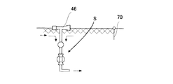
収集装置14は、この実施の形態では、処理船本体10に取り付けられた固定式収集装置44と、移動可能な移動式収集装置46とがある。固定式収集装置44は湖沼の流れや風で移動する藻類を取り込むもので、ダクト30の先端側に設置されており、ラッパ状に外側に広がる吸込部48を有している。固定式収集装置44は、単にフロート28とシート50で構成されるものでもよく、漏斗状の構造物でもよい。吸込部48の水深は水面から温度躍層の間となるが、望ましくは50cm以下、さらに望ましくは20cm以下となる。シート50がメッシュやろ布の場合には、藻類を濃縮して収集できる。
In this embodiment, the
吸込部48の先端にクロロフィル測定器のような藻類センサまたは濁度計を取り付け、一定濃度以上の藻類が流入した場合に運転を開始するなどの制御も可能である。また、この収集装置14を水深方向に上下可動にして、藻類センサと組み合わせ、最も藻類の多い水深の水を吸込むようにしてもよい。吸込部48の先端に流木やゴミ、枯葉の流入を防止する流木よけを取り付けるようにしてもよい。この流木よけは格子状のものでも、メッシュ状のものでも構わない。この流木よけは魚類の進入防止の役目も果たす。
An algae sensor such as a chlorophyll measuring device or a turbidimeter can be attached to the tip of the
図4(a)は固定式収集装置44の変形例を示すもので、吸込部48の内側に水流発生装置を取り付け、藻類の送り込みを促進するようにしたものである。藻類は壁面に停留しやすいため、この水流発生装置により容易に藻類を装置へ移送できる。
FIG. 4 (a) shows a modification of the fixed
図4(b)は吸込部48の底部を傾斜させ、内部に回転ベルト52を有する藻類汲み上げ装置54を設けた場合の図である。藻類が水面付近に存在する場合にはこの方法が有効である。汲み上げ部分をろ過膜で構成することで、藻類を濃縮するようにしてもよい。また、汲み上げ部分を持たない場合、回転ベルト52を不織布などにして、スクレーパーと組み合わせることでも濃縮収集ができる。図4(c)は収集装置14の先端に開閉可能な藻類掻き寄せ装置55を取り付けた場合の図である。これにより藻類取り込み領域を広くでき、掻き寄せ装置55を閉じることによってさらに掻き寄せた藻類を逃さずに処理することが可能となる。
FIG. 4B is a view when the bottom of the
移動式収集装置46は、小型の吸込部48aとポンプ38cとを備え、フレキシブルなホース56によってダクト30に接続されている。図5に示すのは、固定式収集装置44と同様の吸込部48aと、フロート28とを備えている。フロート28の取り付け深さを変えることで、取込深さを変えることができる。この装置の吸込み深さは望ましくは水面から50cm以下、さらに望ましくは20cm以下である。吸込部48aには図示しないハンドルが設けられ、例えば、船上から人手により、あるいはクレーン等の機械によって位置決め操作する。
The
湖沼は複雑な地形をしていることが多く、藻類が発生している水域に処理船Sが近づけない場合が多い。藻類は特に水が停留しやすいワンドや構造物の際に停留することが多いため、小型の移動式収集装置46で藻類を収集することが有効になる。特に、岸辺の駆け上がり部分や浅瀬部分は藻類の発生源となる可能性を持つため、これらの場所に投錨して固定することもできる。
Lakes often have complex terrain, and there are many cases where the treatment ship S cannot approach the water area where algae are generated. Since algae often stays in the case of a wand or structure in which water is likely to stay, it is effective to collect the algae with a small
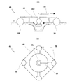
図6は、他の変形例であり、水面の最表層に存在する藻類の収集を目的とした移動式収集装置46で、吸込部48bの全体形状は扁平で、周囲に均等に吸込口が開口し、中央に水中ポンプ38dを備えている。先の場合と同様に、フロート28の取り付け深さを変えることで、その吸込口が水面よりも低い位置になるように設定してある。この装置では表層の藻類は吸込部48bの端より中央に向かって流れ込むため、表層の藻類を全方位から取り込むことが可能である。この装置の取込深さは20cm以下がよいが、望ましくは5cm以下、さらに望ましくは2cm以下である。
FIG. 6 shows another modification, which is a
沈降槽18は、処理船本体10からこれを囲むように延びて設置された枠体58から垂下する仕切りスクリーン60から構成されており、これらは処理船Sが目的箇所へ航行する際は巻き上げて、または取り外して収容することができ、枠体58は処理船本体10上に収納可能になっている。枠体58と仕切りスクリーン60が沈降槽形成手段20を構成している。枠体58にはフロート28が取り付けられ、水上でスクリーン60を支持する際の負荷を軽減している。仕切りスクリーン60の深さは、湖底まで届く必要はなく、例えば藻類が発生すると考えられている温度躍層まででよい。この温度躍層は湖沼などの地形や流入河川の水量などによって異なるが、通常水面から20m以下となる。特に盛夏期においては5m程度にまで浅くなるため、この深さが好ましいものとなる。水深が浅く、温度躍層が存在しない水域では、仕切りスクリーン60の深さは浮上している藻類を堰きとめるだけの長さがあればよい。仕切りスクリーン60は処理船本体10により支持されているので、沈降槽18を設置した状態で処理船本体10を移動させることも、高速でない限り可能である。
The settling
このように構成された処理船Sの動作を説明する。処理船Sは、枠体58および仕切りスクリーン60を収納した状態で目的の場所まで航行し、そこでこれらを展開して沈降槽18を形成する。なお、処理船Sに風向計を取り付け、そのデータを基にして自動的に風上に船首を向けるような操縦システムを設置していもよい。これにより、風に乗り流れてくる藻類を効率的に回収することができる。処理船の上部に帆をつけるなどして簡易に風上へ向けることも可能である。この処理船は左右対称の形状をしており、いずれの方向からも藻類を取り入れることができる。風向計からの情報をもとにダクト内の水流方向を変えて処理を行うことも可能である。湖沼のような電力の供給が困難な場所においては、太陽電池や燃料電池などの蓄電器を用いて処理に必要な電力を供給することも可能である。処理水は、固定式収集装置44および/または移動式収集装置46を用いて収集され、不活化装置16のダクト30に導入されてパルス放電処理を受ける。
The operation of the processing ship S configured as above will be described. The processing ship S navigates to a target place with the
水中でのパルス放電では水中の電極32先端から放電路が形成され、紫外線や衝撃波、高電界、ラジカルが発生する。放電路付近に藻類が存在する場合には、発生した衝撃波や高電界により細胞内の気泡が破壊されるため藻類の沈降が起こる。また気泡の破壊だけでなく、電界強度の高い領域においては細胞内部も一部破壊される場合もあり、生命活動維持できずに藻類が死滅する。パルス放電式処理では発生した衝撃圧力は瞬間的であるため、放電路およびその付近の水はほとんど移動せず、放電による新たな流れが発生しない。このため水流がない水域での処理後の藻類は垂直に沈降する。処理された藻類を含む水は、一部は排出口36から、一部は沈降槽18への流出口42から排出される。流出口42は水面に開口しているので、浮上している藻類はここから多く排出される。
In pulse discharge in water, a discharge path is formed from the tip of the
後段側のポンプ38bは前段側のポンプ38aより排水量が多く設定されているので、沈降槽18内には、図示するような循環流が形成される。循環流は2つのポンプ38a,38bの排水量の差によって得られるので、これを調整することによって循環流量を調整することができる。流出口42から排出された処理水が沈降槽18内を流れる間に、気泡を破壊された藻類は沈降して分離される。未破壊の藻類は浮上したままでやがて循環流に乗って流入口40からダクト30に流入し、放電処理を受ける。このようにして繰り返し循環処理することにより、藻類濃度の高い処理水を処理することができる。
Since the rear-
収集装置14から取り入れる処理水と、循環する量の割合は、主に処理水に含まれる藻類の量や放電処理による気泡破壊の有効性で決める。藻類量が多い場合、あるいは藻類が沈降しにくいタイプである場合には、循環量の比率を高めるために、前段ポンプ38aの吸込量比率を減らすように調整し、逆に、藻類量が少ない場合、あるいは藻類が沈降しやすいタイプである場合には、循環量の比率を下げるために、後段ポンプ38bの吸込量比率を減らすように調整する。
The ratio of the treated water taken in from the
このように、沈降槽18を用いることにより、取り込んだ処理水に充分な処理時間を確保することができる。すなわち、藻類の濃度が高い場合には、ダクト30直通処理では、充分に処理されない藻類をそのまま排出することなく、閉鎖水域を循環させながら処理する。しかも、ダクト30で処理された処理水は、沈降槽18を通過する間に、失活した藻類が沈降するので、ダクト30に戻る時には藻類が減少しており、処理効率も高くなる。循環処理の方法として、流入口40と流出口42とを配管で接続して返送する方法も考えられるが、その場合は設備が過大となり、また途中で沈降したものを分離する手段を設ける等すればさらに大がかりとなってしまう。この実施の形態のように、処理船本体10の周囲をスクリーン60で囲んで閉鎖領域をつくり循環させれば、設備コストが小さく、かつ自然に沈降した藻類を分離する作用を得ることができる。
Thus, by using the
図7は、循環量の調整をより効果的に行うようにした変形例を示すものである。この実施の形態では、ダクト30の前後端部と、流入口40と流出口42にそれぞれ開閉弁62a〜62dが設けられており、開閉弁62a〜62dの調整によって、ダクト30を直通する流量と循環する流量をそれぞれ調整することができる。藻類濃度はダクト内や沈降槽に取り付けられたクロロフィル計や濁度計からの信号をもとに決定する。すなわち、藻類濃度が低い場合、図8(a)に示すように、沈降槽18へ通じる開閉弁62b,62cを閉とすれば、全てがダクト30を直通する処理となる。この場合は、沈降槽18を使用しないことになるので、枠体58やスクリーン60を収納状態で処理でき、従って、航行中でも処理ができる。
FIG. 7 shows a modification in which the circulation amount is adjusted more effectively. In this embodiment, on-off
藻類濃度が中レベルの場合は、図8(b)に示すように全部の開閉弁62a〜62dを開とする。この場合は、図7に示すように、図2の場合と同じ処理モードとなり、ポンプ38a,38b流量差できまる所定の循環比率となる。藻類濃度が高レベルの場合は、図8(b)の運転モードで運転していると沈降槽18内に浮上藻類が溜まってくる。その場合は、図8(c)に示すように、沈降槽18へ通じる開閉弁62b,62cを開とし、流入口40と排出口36の開閉弁62a,62dを閉とし、完全な循環処理とする。この場合は、前段のポンプ38aを停止する。このように、この実施の形態では、状況に応じて効率的な運転モードを選択することができる。
When the algal concentration is at a medium level, all the on-off
図9は、沈降槽18内の藻類の停留を防止するための他の実施の形態を示すものである。図9(a)にはスクリュー64を用いた沈降槽循環手段を示す。1個所もしくは数箇所にスクリュー64を配置してダクト30の流出口42から排出される処理水の藻類を停留なく、流入口40へ移送する。図9(b)は沈降槽18中にスクリーン66を垂らし、流路を規制することによって藻類の停留を防止するものである。スクリーン66は気象条件や湖沼の条件の変化に対応できるように、容易に場所を移動できるものが良い。スクリーン66の深さは、表層に停留している藻類の移送を目的としているために、仕切りスクリーン60と同じ程度でもよいが、最表層に藻類が浮遊している場合には1m程度でもよい。沈降槽18やダクト30の流入口40/流出口42に付近に藻類センサを設置し、処理状態に応じて循環量や循環速度を制御することも可能である。
FIG. 9 shows another embodiment for preventing the algae from staying in the
図10〜図11は、上記のような処理船Sによる処理をより効率的に行うための処理システムを示す図である。以下の説明では、沈降槽18は必要に応じて用いてもよいし、用いなくても良い。
この処理システムは、処理船Sと藻類を堰き止めて処理しやすくする分画壁70とから構成されている。すなわち、ダムなどの流入河川を持つ湖沼の流入部に藻類が発生している場合、その下流または風下方向に分画壁70を設置し、その上流側の領域に処理船Sを配置する。これにより、水面付近に浮遊している藻類は、河川の流れや風に運ばれて分画壁70により堰き止められ、効率的に処理船により処理される。
FIGS. 10-11 is a figure which shows the processing system for performing the process by the above processing boats S more efficiently. In the following description, the
This processing system includes a processing vessel S and a
分画壁70は、フロート28から吊り下げられたシートからなり、オイルフェンスなどと同じ構造である。その深さは、湖底まで届く必要はなく、藻類が発生すると考えられている温度躍層まででよい。湖底付近は水面よりも水温が低いため、藻類は障害物がない限り水面へと上昇することはなく、ダムなどの水深の深い湖沼に置いては、さらに水深の深い部分に流れてゆく。水深が浅く、温度躍層が存在しない水域では、分画壁70の深さは浮上している藻類を堰きとめるだけの長さがあればよい。
The
そして、このように配置した分画壁70より上流側の藻類が浮遊している水域に藻類処理船Sを設置し、分画壁70上流側に停留している藻類を吸引して沈降処理を行う。沈降処理された藻類は湖底へ向けて沈降するが、処理前後の藻類の比重は大きく変化しないために沈降には数分から数十時間を要する。沈降した藻類は水温の低い水流に乗り、分画壁70下方を通り抜け、下流域へと移動する。やがて低水温と日照量の少なさのため休眠状態となり、藻類は増殖できなくなる。
このシステムにおいては、上流から枯葉や流木、ゴミ等が流れ、分画壁70に停留することが多い。このためこれらの障害物の処理船Sへの吸い込みを避けるために、分画壁70と処理船Sを分離して配置しておくことが望ましいが、この限りではなく、スペース的な問題があるような場合には分画壁70の途中に組み入れても構わない。
And the algae processing ship S is installed in the water area in which the algae upstream from the
In this system, dead leaves, driftwood, garbage, etc. flow from the upstream and often stop on the
図11(a)は移動式収集装置46(図1、図5、図6参照)を備えた処理船Sを使った藻類処理システムを示すものである。湖沼は複雑な地形をしていることが多く、藻類が発生している水域に処理船Sが近づけない場合が多い。藻類は特に水が停留しやすいワンドや構造物の際に停留することが多いため、小型の移動式収集装置46で藻類を収集する。ワンドや駆け上がり部分などは藻類の発生源となる可能性を持つため、発生初期にこの領域を分画壁70で隔離し、この分画壁70の内部の藻類を処理することで、湖沼全体への拡散を防止できる。
FIG. 11A shows an algae treatment system using a treatment ship S provided with a mobile collection device 46 (see FIGS. 1, 5, and 6). Lakes often have complex terrain, and there are many cases where the treatment ship S cannot approach the water area where algae are generated. Algae are often retained especially in the case of wands and structures in which water is likely to be retained, and therefore the algae is collected by a small
図11(b)は分画壁70を多段に用いた処理システムの一例である。この図では分画壁70にゲート72を持つものを使用している。通常、藻類は流れに乗り上流から下流に移動するが、地形や気象条件、特に風によっては逆流が発生して、上流方向へ移動することがある。このため分画壁70で停留させた藻類は上流方向に拡散してしまう恐れが生じる。この拡散を防止するために、この実施の形態では、開閉自在なゲート72を持つ分画壁70を処理船Sの上流及び下流に配置し、一度収集した藻類を拡散させないようにする。このゲート72にネットを取り付けておけば、流木等の障害物を回収できる。もちろん、この処理船Sに小型の移動式収集装置46を装備すれば、分画壁70で仕切られた水域の角部や分画壁70際に停留する藻類を収集できる。
FIG. 11B is an example of a processing system that uses the
図12および図13は、湖沼の水面付近に浮遊する藻類を処理船Sに向けて導くための移動装置を示す図である。水面付近に浮遊する藻類をポンプ等で発生した水流で処理船Sへ向けて移動させて処理することで、効率のよい処理が可能となる。図12(a)では、ポンプ38eによって水流を発生させ、図12(b)では水中からの散気装置74による散気および気中でのコンプレッサ76やブロアによる風で水流を発生させ、また、図13では噴水装置78で水流を発生させる様子を示す。
12 and 13 are diagrams showing a moving device for guiding the algae floating near the water surface of the lake toward the processing ship S. FIG. By moving the algae floating in the vicinity of the water surface toward the processing ship S with the water flow generated by a pump or the like, the processing can be performed efficiently. In FIG. 12A, a water flow is generated by the
図14は、処理船Sあるいは不活化装置16を水中に潜行させるような形式とし、移動式収集装置46を用いて、表層に浮遊する藻類を沈降処理するものである。この場合、図に示すように、処理船Sの排出口36を下方に向けることで低水温域に藻類を吐出して不活性化することが可能である。一方、処理船Sの排出口36を水面に向けることで水域内に上下方向の水流が発生して循環ができるため効率的な処理となる。また、このような移動による散気や循環により水に空気中の酸素が溶解して藻類の発生を抑制できるだけでなく、不活化装置16と併用することでより一層の増殖防止効果が期待できる。いずれの移動装置も水域の中央に配置するだけでなく、収集装置14、分画壁70や湖岸に設置することも可能である。
FIG. 14 shows a form in which the treatment ship S or the
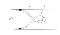
図15は、藻類を堰き止めるだけでなく、処理船Sに向けて誘導する誘導壁80を有する藻類処理システムを示す図である。藻類が問題となるような湖沼では定期的に水質を調査する場合が多い。水質調査船を用いて湖沼中の数箇所でサンプリングを行うことが通常行われている。上述のような固定した分画壁70を利用した場合には、このような調査船や清掃船などの作業船が通過できずに通行の障害となる。このため作業船が通過できる藻類の収集方法が必須となる。
FIG. 15 is a diagram showing an algae treatment system having a
この実施の形態の方法では、水流や風で移動する表層の藻類に対し、誘導壁80を設けて処理船Sへと導くようにする。誘導壁80は分画壁70と同様にオイルフェンスと同様の構造が望ましいが、例えば片端にフロート28を取り付けるなどして、湖沼の両岸とを結び付けないようにする。なお、藻類はこの誘導壁80付近に停留するため、前述の移動装置を併用し、移動させて処理船Sへと誘導するようにしてもよい。
In the method according to this embodiment, a
拡散防止用の分画壁70を用いた場合において、その付近の水流速度が比較的早い場合には、藻類が表層の水流とともに分画壁70を押しのけて、分画壁70下方より通過することが起こる。この実施の形態では、このような状況においても、表層の流れを妨げないので、有効である。
When the
図16は、複数個の分画壁70を交互に配置し、処理船Sの通行域を広くした場合のシステムである。水流や風で運ばれた藻類は、一部が分画壁70と岸との角部に停留するが、大部分は分画壁70をすり抜けて処理船Sに流入する。角部に停留した藻類は移動式小型種集装置で収集すればよい。このシステムでは、表層の流れを大きく遮断しないために、処理船Sが容易に通過できるだけでなく、水鳥や魚の移動も容易であり、自然への悪影響が小さい。また、岸付近の水深が浅い場合には、処理船Sを座礁させるおそれも無く、安定に稼動できる藻類収集手段となる。
FIG. 16 shows a system in which a plurality of
10 処理船本体
12 藻類処理装置
14 収集装置
16 不活化装置
18 沈降槽
20 沈降槽形成手段
22 主板
24 連結板
26 副板
28 フロート
30 ダクト
32 電極
34 放電装置
36 排出口
38a〜38f ポンプ
40 流入口
42 流出口
44 固定式収集装置
46 移動式収集装置
48、48a、48b 吸込部
50 シート
52 回転ベルト
54 藻類汲み上げ装置
55 藻類掻き寄せ装置
56 ホース
58 枠体
60 仕切りスクリーン
62a〜62d 開閉弁
64 スクリュー
66 スクリーン
70 分画壁
72 ゲート
74 散気装置
76 コンプレッサ
78 噴水装置
80 誘導壁
S 処理船
DESCRIPTION OF
Claims (6)
該処理船本体に搭載され、藻類の浮力を失わせる不活化装置と、
該処理船本体に搭載され、水域中の藻類を前記不活化装置に導く収集手段と
を持つことを特徴とする藻類処理船。 A treatment ship body capable of navigating the water area,
An inactivation device that is mounted on the main body of the treatment vessel and loses the buoyancy of algae,
An algae processing ship mounted on the main body of the processing ship and having collecting means for guiding algae in the water area to the inactivation device.
水域中の藻類を前記不活化装置に導く誘導手段と
を持つことを特徴とする藻類処理システム。
A treatment ship having an inactivation device for losing the buoyancy of algae;
An algae treatment system comprising: guidance means for guiding algae in the water area to the inactivation device.
Priority Applications (1)
| Application Number | Priority Date | Filing Date | Title |
|---|---|---|---|
| JP2006149094A JP2007319002A (en) | 2006-05-30 | 2006-05-30 | Algae-treating ship and algae-treating system |
Applications Claiming Priority (1)
| Application Number | Priority Date | Filing Date | Title |
|---|---|---|---|
| JP2006149094A JP2007319002A (en) | 2006-05-30 | 2006-05-30 | Algae-treating ship and algae-treating system |
Publications (1)
| Publication Number | Publication Date |
|---|---|
| JP2007319002A true JP2007319002A (en) | 2007-12-13 |
Family
ID=38852318
Family Applications (1)
| Application Number | Title | Priority Date | Filing Date |
|---|---|---|---|
| JP2006149094A Pending JP2007319002A (en) | 2006-05-30 | 2006-05-30 | Algae-treating ship and algae-treating system |
Country Status (1)
| Country | Link |
|---|---|
| JP (1) | JP2007319002A (en) |
Cited By (21)
| Publication number | Priority date | Publication date | Assignee | Title |
|---|---|---|---|---|
| WO2009134358A1 (en) * | 2008-04-28 | 2009-11-05 | Optiswitch Technology Corporation | Apparatus and method for producing biofuel from algae by application of shaped pulsed pressure waves |
| CN101624821B (en) * | 2009-05-11 | 2011-09-14 | 中国科学院南京地理与湖泊研究所 | Large simulated type water-surface blue-green algae removing device |
| JP2012019749A (en) * | 2010-07-15 | 2012-02-02 | Chugoku Electric Power Co Inc:The | Method of suppressing growth of water bloom |
| KR101113975B1 (en) | 2009-03-10 | 2012-03-05 | (주)상승글로벌 | alga remove ship |
| US20140197113A1 (en) * | 2013-01-14 | 2014-07-17 | Palo Alto Research Center Incorporated | Systems and apparatus for removal of harmful algae blooms (hab) and transparent exopolymer particles (tep) |
| JP2014227706A (en) * | 2013-05-21 | 2014-12-08 | 株式会社 三雅 | Blue-green algae collection device |
| KR101624118B1 (en) * | 2016-02-22 | 2016-05-25 | 한국과학기술연구원 | Water purification apparatus having multistage model |
| JP2017109155A (en) * | 2015-12-15 | 2017-06-22 | 真一 本村 | Water bloom recovery device |
| CN108043106A (en) * | 2018-01-17 | 2018-05-18 | 苏州飞驰环保科技股份有限公司 | A kind of fish gill formula filtration system of cyanobacteria boat for harvesting |
| CN109052585A (en) * | 2018-10-16 | 2018-12-21 | 南京大学 | A kind of electrochemical appliance removing cyanobacteria and nitrogen and phosphorous nutrient |
| CN109110352A (en) * | 2018-09-17 | 2019-01-01 | 南京信息工程大学 | Unmanned garbage treatment ship |
| CN109371942A (en) * | 2018-12-03 | 2019-02-22 | 山东省水利科学研究院 | A kind of floating algae controlling device and administering method |
| KR20200075696A (en) * | 2018-12-18 | 2020-06-26 | 차태영 | Removal apparatus for green algae |
| CN112627134A (en) * | 2020-11-25 | 2021-04-09 | 李安清 | Green algae cleaning equipment in lake |
| CN113292198A (en) * | 2021-04-29 | 2021-08-24 | 珠江水利委员会珠江水利科学研究院 | Water treatment facilities based on water ecosystem |
| CN114991102A (en) * | 2022-06-13 | 2022-09-02 | 广东祥实建设有限公司 | Be used for river course water ecological management equipment |
| CN115012465A (en) * | 2022-07-09 | 2022-09-06 | 华北水利水电大学 | Algae sediment collecting system for side slope of north-south water transfer channel |
| CN115142499A (en) * | 2022-07-09 | 2022-10-04 | 华北水利水电大学 | Algae sediment collecting device for slope surface of water channel of hydraulic engineering |
| CN115354638A (en) * | 2022-09-22 | 2022-11-18 | 江苏东方生态清淤工程有限公司 | System and method suitable for collecting floating algae and accumulated silt in near-shore area |
| CN115636060A (en) * | 2022-10-19 | 2023-01-24 | 河海大学 | Multifunctional cleaning ship for performing water purification treatment on lakes |
| JP7394452B2 (en) | 2020-02-29 | 2023-12-08 | 有限会社アルファサービス | Algae removal equipment and algae treatment system |
Citations (6)
| Publication number | Priority date | Publication date | Assignee | Title |
|---|---|---|---|---|
| JPH01187211A (en) * | 1988-01-22 | 1989-07-26 | Penta Ocean Constr Co Ltd | Treating recoverer for water-bloom |
| JPH07274661A (en) * | 1994-04-08 | 1995-10-24 | Mitsubishi Heavy Ind Ltd | Water bloom catcher |
| JPH11319824A (en) * | 1998-05-14 | 1999-11-24 | Kajima Corp | Sedimentation method of water surface floating organism and device therefor |
| JP2001073350A (en) * | 1999-09-07 | 2001-03-21 | Ishigaki Co Ltd | Water quality clarification equipment |
| JP2004188230A (en) * | 2002-07-04 | 2004-07-08 | Ryoyo Sangyo Kk | Method for exterminating water bloom |
| JP2005185970A (en) * | 2003-12-25 | 2005-07-14 | Kaiyo Kaihatsu Gijutsu Kenkyusho:Kk | Method and apparatus for improving quality of water |
-
2006
- 2006-05-30 JP JP2006149094A patent/JP2007319002A/en active Pending
Patent Citations (6)
| Publication number | Priority date | Publication date | Assignee | Title |
|---|---|---|---|---|
| JPH01187211A (en) * | 1988-01-22 | 1989-07-26 | Penta Ocean Constr Co Ltd | Treating recoverer for water-bloom |
| JPH07274661A (en) * | 1994-04-08 | 1995-10-24 | Mitsubishi Heavy Ind Ltd | Water bloom catcher |
| JPH11319824A (en) * | 1998-05-14 | 1999-11-24 | Kajima Corp | Sedimentation method of water surface floating organism and device therefor |
| JP2001073350A (en) * | 1999-09-07 | 2001-03-21 | Ishigaki Co Ltd | Water quality clarification equipment |
| JP2004188230A (en) * | 2002-07-04 | 2004-07-08 | Ryoyo Sangyo Kk | Method for exterminating water bloom |
| JP2005185970A (en) * | 2003-12-25 | 2005-07-14 | Kaiyo Kaihatsu Gijutsu Kenkyusho:Kk | Method and apparatus for improving quality of water |
Cited By (29)
| Publication number | Priority date | Publication date | Assignee | Title |
|---|---|---|---|---|
| WO2009134358A1 (en) * | 2008-04-28 | 2009-11-05 | Optiswitch Technology Corporation | Apparatus and method for producing biofuel from algae by application of shaped pulsed pressure waves |
| KR101113975B1 (en) | 2009-03-10 | 2012-03-05 | (주)상승글로벌 | alga remove ship |
| CN101624821B (en) * | 2009-05-11 | 2011-09-14 | 中国科学院南京地理与湖泊研究所 | Large simulated type water-surface blue-green algae removing device |
| JP2012019749A (en) * | 2010-07-15 | 2012-02-02 | Chugoku Electric Power Co Inc:The | Method of suppressing growth of water bloom |
| US20140197113A1 (en) * | 2013-01-14 | 2014-07-17 | Palo Alto Research Center Incorporated | Systems and apparatus for removal of harmful algae blooms (hab) and transparent exopolymer particles (tep) |
| US9624116B2 (en) * | 2013-01-14 | 2017-04-18 | Palo Alto Research Center Incorporated | Systems and apparatus for removal of harmful algae blooms (HAB) and transparent exopolymer particles (TEP) |
| JP2014227706A (en) * | 2013-05-21 | 2014-12-08 | 株式会社 三雅 | Blue-green algae collection device |
| JP2017109155A (en) * | 2015-12-15 | 2017-06-22 | 真一 本村 | Water bloom recovery device |
| KR101624118B1 (en) * | 2016-02-22 | 2016-05-25 | 한국과학기술연구원 | Water purification apparatus having multistage model |
| CN108043106A (en) * | 2018-01-17 | 2018-05-18 | 苏州飞驰环保科技股份有限公司 | A kind of fish gill formula filtration system of cyanobacteria boat for harvesting |
| CN108043106B (en) * | 2018-01-17 | 2023-11-21 | 苏州飞驰环保科技股份有限公司 | Fish gill type filtering system of blue algae harvesting ship |
| CN109110352A (en) * | 2018-09-17 | 2019-01-01 | 南京信息工程大学 | Unmanned garbage treatment ship |
| CN109052585A (en) * | 2018-10-16 | 2018-12-21 | 南京大学 | A kind of electrochemical appliance removing cyanobacteria and nitrogen and phosphorous nutrient |
| CN109371942A (en) * | 2018-12-03 | 2019-02-22 | 山东省水利科学研究院 | A kind of floating algae controlling device and administering method |
| KR102224468B1 (en) * | 2018-12-18 | 2021-03-05 | 차태영 | Removal apparatus for green algae |
| KR20200075696A (en) * | 2018-12-18 | 2020-06-26 | 차태영 | Removal apparatus for green algae |
| JP7394452B2 (en) | 2020-02-29 | 2023-12-08 | 有限会社アルファサービス | Algae removal equipment and algae treatment system |
| CN112627134B (en) * | 2020-11-25 | 2022-10-04 | 北京未空科技有限公司 | Green algae cleaning equipment in lake |
| CN112627134A (en) * | 2020-11-25 | 2021-04-09 | 李安清 | Green algae cleaning equipment in lake |
| CN113292198A (en) * | 2021-04-29 | 2021-08-24 | 珠江水利委员会珠江水利科学研究院 | Water treatment facilities based on water ecosystem |
| CN113292198B (en) * | 2021-04-29 | 2022-03-29 | 珠江水利委员会珠江水利科学研究院 | Water treatment facilities based on water ecosystem |
| CN114991102A (en) * | 2022-06-13 | 2022-09-02 | 广东祥实建设有限公司 | Be used for river course water ecological management equipment |
| CN115012465B (en) * | 2022-07-09 | 2023-08-15 | 华北水利水电大学 | Algae sediment collection system for south-to-north-adjustment channel side slope |
| CN115142499B (en) * | 2022-07-09 | 2023-09-15 | 华北水利水电大学 | Algae sediment collecting device for hydraulic engineering ditch slope |
| CN115142499A (en) * | 2022-07-09 | 2022-10-04 | 华北水利水电大学 | Algae sediment collecting device for slope surface of water channel of hydraulic engineering |
| CN115012465A (en) * | 2022-07-09 | 2022-09-06 | 华北水利水电大学 | Algae sediment collecting system for side slope of north-south water transfer channel |
| CN115354638A (en) * | 2022-09-22 | 2022-11-18 | 江苏东方生态清淤工程有限公司 | System and method suitable for collecting floating algae and accumulated silt in near-shore area |
| CN115636060A (en) * | 2022-10-19 | 2023-01-24 | 河海大学 | Multifunctional cleaning ship for performing water purification treatment on lakes |
| CN115636060B (en) * | 2022-10-19 | 2024-02-13 | 河海大学 | Multifunctional cleaning ship for purifying lake water |
Similar Documents
| Publication | Publication Date | Title |
|---|---|---|
| JP2007319002A (en) | Algae-treating ship and algae-treating system | |
| KR101602571B1 (en) | Green tide removal apparatus for using uv-c lamp and ultrasonic wave generator | |
| CN107859016B (en) | Algae removal system is collected in enrichment of water bloom algae blocking | |
| JP5822644B2 (en) | Cleaning device for filtration layer in seawater infiltration. | |
| WO2012107936A2 (en) | A devise and method to separate at entry polluted water from clean water and treat it inside a river and inside a lake | |
| KR102418093B1 (en) | Recovery Apparatus of Green Algae and Floating | |
| RU2720096C1 (en) | Fish breeding apparatus and method | |
| CN203530947U (en) | Movable river surface cleaning device | |
| CN111592178B (en) | Treatment method of near-shore water body blue-green algae comprehensive treatment device | |
| JP2021137672A (en) | Algae removal device and algae treatment system | |
| CN103755085B (en) | Device and method for removing algal bloom and purifying algae source in branch reservoir bay of channel reservoir | |
| KR101753783B1 (en) | Boat for Removeing Algae and Pollutants With Recharging Station | |
| KR101547856B1 (en) | System for purifying water which uses floating type | |
| CN110759515B (en) | Polluted river water treatment ship and treatment method | |
| JP2007107373A (en) | Method for collecting floating marine algae | |
| JP2020116515A (en) | Microcystis concentration and recovery system | |
| KR101334276B1 (en) | Removing apparatus and the method of water-bloom and red-tide in water | |
| KR102272151B1 (en) | Inductive Purification Apparatus of Green Algae | |
| CN213014197U (en) | Device that river lake algae normal position was collected and was handled | |
| KR101502048B1 (en) | Purification device for river | |
| JPH10263590A (en) | Method for cleaning water utilizing green waterweed and ultrasonic wave and device therefor | |
| KR20160000687A (en) | Green algae removal system and method of removing green algae using same | |
| CN110697973A (en) | Sewage draining port water treatment equipment for urban drainage pipeline | |
| JP2883771B2 (en) | Purification equipment for lakes and marshes | |
| JP3918154B2 (en) | Wave absorber with floating algae recovery function |
Legal Events
| Date | Code | Title | Description |
|---|---|---|---|
| A621 | Written request for application examination |
Free format text: JAPANESE INTERMEDIATE CODE: A621 Effective date: 20090122 |
|
| RD04 | Notification of resignation of power of attorney |
Free format text: JAPANESE INTERMEDIATE CODE: A7424 Effective date: 20090330 |
|
| A711 | Notification of change in applicant |
Effective date: 20091124 Free format text: JAPANESE INTERMEDIATE CODE: A712 |
|
| A977 | Report on retrieval |
Free format text: JAPANESE INTERMEDIATE CODE: A971007 Effective date: 20110323 |
|
| A131 | Notification of reasons for refusal |
Free format text: JAPANESE INTERMEDIATE CODE: A131 Effective date: 20110325 |
|
| A02 | Decision of refusal |
Free format text: JAPANESE INTERMEDIATE CODE: A02 Effective date: 20110714 |