JP2007313837A - Transparent inkjet recording sheet - Google Patents
Transparent inkjet recording sheet Download PDFInfo
- Publication number
- JP2007313837A JP2007313837A JP2006148233A JP2006148233A JP2007313837A JP 2007313837 A JP2007313837 A JP 2007313837A JP 2006148233 A JP2006148233 A JP 2006148233A JP 2006148233 A JP2006148233 A JP 2006148233A JP 2007313837 A JP2007313837 A JP 2007313837A
- Authority
- JP
- Japan
- Prior art keywords
- recording sheet
- spherical particles
- particles
- back layer
- transparent
- Prior art date
- Legal status (The legal status is an assumption and is not a legal conclusion. Google has not performed a legal analysis and makes no representation as to the accuracy of the status listed.)
- Pending
Links
Images
Abstract
Description
本発明は、透明インクジェット記録シートに関するものである。さらに、高い平滑性を有し、耐ブロッキング性に優れ、インク裏移りのない透明インクジェット記録シートに関する。 The present invention relates to a transparent inkjet recording sheet. Furthermore, the present invention relates to a transparent ink jet recording sheet having high smoothness, excellent blocking resistance, and no ink transfer.
インクジェットによる記録方式は、近年広く普及し多種多様な印刷物を提供している。カラーインクジェットにおいては、写真調の印刷を得るために記録シートは、表面が平滑で光沢のある記録シートが用いられるようになった。また、OHPシートに記録する場合においても、基材は、平滑なフィルムである。これらの平滑な記録シートは、静電気により帯電しやすいため、複数の記録シートを重ねてセットして、自動で一枚ずつ給紙する自動給紙機構を採用しているインクジェットプリンタでは、ブロッキングによる自動給紙時の記録シートの重送が発生しやすい。 Inkjet recording systems have become widespread in recent years and provide a wide variety of printed materials. In color ink jet, a recording sheet having a smooth surface and gloss has been used to obtain a photographic print. Also, when recording on an OHP sheet, the substrate is a smooth film. Since these smooth recording sheets are easily charged by static electricity, an inkjet printer that employs an automatic sheet feeding mechanism that automatically sets a plurality of recording sheets and feeds them one by one automatically uses blocking. Double feeding of recording sheets during feeding is likely to occur.
この問題を解決するために特許文献1では、基材の背面層に球状微粒子ポリマーを含有させる方法が提供された。しかしながら、受像層の表面が平滑なものや、受像層にインクを吸着する多孔質粒子を含有しないものでは、十分な効果が見られなかった。特許文献1の方法において、十分な効果を得るために球状粒子の大きさを大きなものにしたり、球状粒子の含有量を多量に含ませると、微球状粒子が取れて粉落ちの新たな問題が発生した。また、球状粒子の含有量を多くすると粒子による光の拡散で背面層が白濁を帯びて、透明インクジェット記録シートを製造することが困難となっていた。
In order to solve this problem,
受像層に多孔質粒子を含有しないで、バインダーのみで形成されるものとして、油性インクジェット用受像層がある。油性インクはソルベントインクとも言われる。この受像層は、印刷直後には、インクが受像層に吸収されなく一部が表面に浮いた状態になっている。そのため、印刷後の記録シートを重ね置くとインクの裏移りの問題が発生していた。
本発明者は、上記の問題を解決すべく透明な樹脂フィルムのような平滑な基材を使った記録シートのブロッキングを防ぎ、インクの裏移りのない透明インクジェット記録シートを提供するものである。さらに、背面層中の球状粒子の含有量と背面層の厚みを少なくして製造コストを安価にするものである。 In order to solve the above problems, the present inventor provides a transparent ink jet recording sheet that prevents blocking of a recording sheet using a smooth substrate such as a transparent resin film and has no ink set-off. Furthermore, the production cost is reduced by reducing the content of the spherical particles in the back layer and the thickness of the back layer.
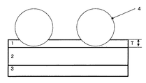
第1発明は、透明基材が透明な樹脂フィルムであり、インク受像層が透明であり、背面層がバインダーと球状粒子からなり下記の要件を満たすことを特徴とする透明インクジェット記録シートである。
(1)球状粒子の平均粒径Dが、1〜15μmの範囲である。
(2)球状粒子の粒径のばらつきが、D±0.4Dμmの範囲内の単分散粒子である。
(3)背面層の厚さTと球状粒子の平均粒径Dの関係が、D−T=0.9−14μmである。
(4)記録シートの全光線透過率が85%以上である。
第2発明は、背面層の厚みTが0.1〜0.5μmの範囲内であることを特徴とする第1発明記載の透明インクジェット記録シートである。背面層を薄くしても、ブロッキングに十分効果があり、コストを安くできる。
第3発明は、受像層が油性インクジェット用受像層であることを特徴とする第1、2発明記載の透明インクジェット記録シートである。インクの吸収が遅い油性インクジェット用受像層であったとしても、インクの裏移りの発生がないものである。
The first invention is a transparent ink jet recording sheet characterized in that the transparent substrate is a transparent resin film, the ink image-receiving layer is transparent, and the back layer is composed of a binder and spherical particles and satisfies the following requirements.
(1) The average particle diameter D of spherical particles is in the range of 1 to 15 μm.
(2) The monodisperse particles have a variation in the particle diameter of the spherical particles within a range of D ± 0.4 D μm.
(3) The relationship between the thickness T of the back layer and the average particle diameter D of the spherical particles is DT = 0.9-14 μm.
(4) The total light transmittance of the recording sheet is 85% or more.
The second invention is the transparent ink jet recording sheet according to the first invention, wherein the thickness T of the back layer is in the range of 0.1 to 0.5 μm. Even if the back layer is made thin, the blocking is sufficiently effective and the cost can be reduced.
A third invention is the transparent ink jet recording sheet according to the first or second invention, wherein the image receiving layer is an image receiving layer for oil-based ink jet. Even if it is an oil-based inkjet image-receiving layer that absorbs ink slowly, there is no occurrence of ink set-off.
本発明のインクジェット記録シートを用いたインクジェットによる印刷では、ブロッキングによる重送がなく、インクの裏移りのない透明な記録シートとなる。また、背面層の厚み薄くできるのでコストを安くすることが可能となった。 In the ink jet printing using the ink jet recording sheet of the present invention, there is no double feeding due to blocking, and a transparent recording sheet without ink back-off is obtained. In addition, since the thickness of the back layer can be reduced, the cost can be reduced.
本発明に用いる透明基材としては、画質の良さ、光沢、平滑性等の点から、透明樹脂フィルムを用いる。樹脂フィルムとしては、ポリエステルフィルム、ポリイミドフィルム、ポリカーボネートフィルム、ポリアミドフィルム、ポリオレフィンフィルム等が挙げられるが、これらの樹脂フィルムの中でも強度、コストの点からポリエステルフィルムを好ましく用いることができる。 As the transparent substrate used in the present invention, a transparent resin film is used in view of good image quality, gloss, smoothness and the like. Examples of the resin film include a polyester film, a polyimide film, a polycarbonate film, a polyamide film, and a polyolefin film. Among these resin films, a polyester film can be preferably used in terms of strength and cost.
基材は、高画質、高光沢な印刷物を得るために、JIS−B0601による中心線平均粗さが0.4μm以下の表面を有するものが好ましい。基材の厚みは、10〜300μm程度のものを用いる。 In order to obtain a high-quality, high-gloss printed matter, the substrate preferably has a surface with a center line average roughness of 0.4 μm or less according to JIS-B0601. The substrate has a thickness of about 10 to 300 μm.
背面層は、バインダーと球状粒子からなるものである。球状粒子は、真球状であるのが好ましい。真球状であると本発明の効果が安定して得られる。球状粒子には、有機粒子と無機粒子があるがどちらの粒子でも用いることができる。 The back layer is composed of a binder and spherical particles. The spherical particles are preferably spherical. The effect of this invention is stably acquired as it is a spherical shape. The spherical particles include organic particles and inorganic particles, but either particle can be used.
有機粒子の材質としては、ポリエチレン、ポリプロピレン、ポリメチルペンテン、ポリスチレン、ポリアクリル酸メチル、ポリアクリル酸エチル、ポリメタクリル酸メチル、ポリメタクリル酸エチル、ポリ酢酸ビニル、ポリ塩化ビニル、エチレン酢酸ビニル共重合樹脂、エポキシ樹脂、尿素−ホルマリン樹脂、ベンゾグアナミン樹脂、メラミン−ホルマリン樹脂等が挙げられる。有機粒子は、架橋粒子と非架橋粒子があるが、背面層塗工液の溶剤に溶解しないものであれば、架橋、非架橋いずれの粒子でも使用できる。無機粒子としては、シリカ粒子が挙げられる。 The organic particles are made of polyethylene, polypropylene, polymethylpentene, polystyrene, polymethyl acrylate, polyethyl acrylate, polymethyl methacrylate, polyethyl methacrylate, polyvinyl acetate, polyvinyl chloride, ethylene vinyl acetate copolymer Resins, epoxy resins, urea-formalin resins, benzoguanamine resins, melamine-formalin resins and the like can be mentioned. The organic particles include cross-linked particles and non-cross-linked particles, but any particles that are cross-linked or non-cross-linked can be used as long as they do not dissolve in the solvent of the back surface coating solution. Examples of the inorganic particles include silica particles.
球状粒子は、図1の背面層の厚みTより大きくする必要があり、要件(1)として、平均粒径Dが1〜15μmの範囲のものとする。前記範囲未満であるとブロッキングに対して効果が低くなる。前記範囲を超えると球状粒子が取れて粉落ちしやすくなる。 The spherical particles need to be larger than the thickness T of the back layer in FIG. 1, and the requirement (1) is that the average particle diameter D is in the range of 1 to 15 μm. If it is less than the above range, the effect on blocking becomes low. If the above range is exceeded, spherical particles can be taken and easily fall off.
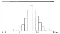
一般にこのような微粒子の大きさの分布は、図2のような正規分布に近いばらつきを持っている。よって、実際にブロッキングに効果のある粒子は、平均粒径よりも大きいところの粒子の働きが作用しているのであり、平均粒径付近及びそれ以下の粒径の粒子は、ブロッキング防止にはほとんど働いていないものである。そのため粒子を背面層に含有する場合、平均粒径の大きなものを含有させる方法か、粒子の含有量を多くして大きな粒子の量を増やす方法を取らざるを得なくなる。前者の方法では、必要以上の大きな粒径の粒子が存在することになり球状粒子が取れて粉落ちしやすくなり、条件によっては、背面層が白濁した。後者の方法では、背面層のコストアップとなったり、背面層が白濁して記録シートとして透明性を求められた場合、不透明となり使用できないものとなった。 In general, the size distribution of such fine particles has a variation close to a normal distribution as shown in FIG. Therefore, particles that are actually effective for blocking act as particles having a particle size larger than the average particle size. It is not working. Therefore, when the particles are contained in the back layer, it is unavoidable to use a method of containing a large average particle diameter or a method of increasing the amount of large particles by increasing the content of particles. In the former method, particles having a larger particle size than necessary existed, and spherical particles were easily removed and powdered off easily. Depending on the conditions, the back layer was clouded. In the latter method, when the cost of the back layer is increased, or when the back layer is cloudy and transparency is required as a recording sheet, it becomes opaque and cannot be used.
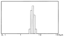
本発明で使用する球状粒子は、要件(2)で規定する粒径のばらつきが、D±0.4Dμmの範囲内の単分散粒子とする。単分散粒子とは、図3で示すように粒径が揃っている粒子を指すものである。一般にこのような単分散粒子は、液晶パネル間のスペーサとして用いられている。ブロッキングに効果のある粒径は、前記のようにサブミクロン未満の超微粒子は、効果がなく、大きさが過大になると受像層にキズが入る問題があった。しかし、本発明の単分散粒子を使えば適正な粒径の粒子のみを使うことができるので、従来に比べて少量で効果を発揮することができる。つまり、少量でもって耐ブロッキング性を得ることができるものである。 The spherical particles used in the present invention are monodisperse particles having a particle size variation defined by the requirement (2) within a range of D ± 0.4 D μm. Monodisperse particles refer to particles having a uniform particle size as shown in FIG. In general, such monodisperse particles are used as spacers between liquid crystal panels. As described above, the ultrafine particles having a particle size effective for blocking of less than submicron are not effective, and there is a problem that the image receiving layer is damaged when the size is excessive. However, if the monodisperse particles of the present invention are used, only particles having an appropriate particle size can be used, and therefore the effect can be exhibited in a small amount compared to the conventional case. That is, blocking resistance can be obtained with a small amount.
単分散粒子は、綜研化学、日本触媒、積水化学工業等が主に液晶パネルのスペーサ用として市販している。いずれのメーカーのものでも、要件(2)の範囲内の平均粒径であれば用いることができる。 Monodisperse particles are commercially available mainly for spacers of liquid crystal panels by Soken Chemical, Nippon Shokubai, Sekisui Chemical, etc. Any manufacturer can use any average particle size within the range of requirement (2).
球状の単分散粒子とともに、図2の一般の粒径分布を持った球状粒子、非球状粒子を他の目的のために本発明の効果を妨げない範囲で含有させてもよい。その含有量は、全粒子量に対して、30重量%未満とする。他の目的とは、例えば背面層を着色するために着色顔料粒子を含ませたりすることを意味する。 In addition to the spherical monodisperse particles, spherical particles and non-spherical particles having the general particle size distribution shown in FIG. 2 may be included for other purposes within a range not impeding the effects of the present invention. The content is less than 30% by weight with respect to the total amount of particles. Other purposes mean, for example, the inclusion of colored pigment particles to color the back layer.
背面層のバインダーとしては、熱可塑性樹脂、熱硬化性樹脂、紫外線硬化性樹脂より用いる。熱可塑性樹脂としては、エチレン−酢酸ビニル共重合体などのオレフィン系共重合体、ポリアミド樹脂、ポリエステル樹脂、天然ゴム、石油系樹脂、ロジン系樹脂、スチレン樹脂などが挙げられる。熱硬化性樹脂としては、たとえばエポキシ樹脂、フェノール樹脂、キシレン樹脂、ユリア樹脂、メラミン樹脂、不飽和ポリエステル樹脂、フラン樹脂、アセトンホルムアルデヒド樹脂、アルキド樹脂、シリコーン系樹脂などが挙げられる。紫外線硬化性樹脂としては紫外線照射により重合反応を起こし、硬化して樹脂となるモノマー又はオリゴマー(又はプレポリマー)であればその種類が制限されず、公知の種々のもの全て使用できる。このようなモノマー又はオリゴマーとしては(ポリ)エステルアクリレート、(ポリ)ウレタンアクリレート、エポキシアクリレート、ポリブタジエンアクリレート、シリコーンアクリレート等やメラミンアクリレートがある。こららの樹脂より球状粒子との接着力が高く且つ基材との接着力の高い樹脂を適宜1種以上選択して用いる。 As the binder for the back layer, a thermoplastic resin, a thermosetting resin, or an ultraviolet curable resin is used. Examples of the thermoplastic resin include olefin copolymers such as ethylene-vinyl acetate copolymer, polyamide resin, polyester resin, natural rubber, petroleum resin, rosin resin, and styrene resin. Examples of the thermosetting resin include epoxy resins, phenol resins, xylene resins, urea resins, melamine resins, unsaturated polyester resins, furan resins, acetone formaldehyde resins, alkyd resins, and silicone resins. The type of the ultraviolet curable resin is not limited as long as it is a monomer or oligomer (or prepolymer) that undergoes a polymerization reaction upon irradiation with ultraviolet rays and is cured to become a resin, and all known various types can be used. Examples of such a monomer or oligomer include (poly) ester acrylate, (poly) urethane acrylate, epoxy acrylate, polybutadiene acrylate, silicone acrylate, and melamine acrylate. One or more types of resins having higher adhesion to spherical particles and higher adhesion to the substrate than these resins are selected and used.
球状粒子に対して強固に接着力を生むことから硬化性樹脂を用いるのが好ましい。 It is preferable to use a curable resin because it produces strong adhesion to spherical particles.
背面層中の球状粒子の含有量は、1〜30重量%の範囲とする。前記範囲未満であると耐ブロッキング性が低下する。前記範囲を超えると粒子による光の散乱により曇って透明性が低下するようになる。また、耐ブロッキング効果は一定以上、上がるものではなく不経済となる。 The content of the spherical particles in the back layer is in the range of 1 to 30% by weight. When it is less than the above range, the blocking resistance is lowered. When the above range is exceeded, the light becomes cloudy due to scattering of light by the particles and the transparency is lowered. Further, the anti-blocking effect does not increase beyond a certain level, and is uneconomical.
図1の背面層の厚みTに比べ、球状粒子が突き出ている大きさが十分でないとブロッキング効果が生まれない。具体的には、要件(3)のD−T=0.9〜14μmの突き出し長さにする必要がある。前記範囲未満であると耐ブロッキング性が低くなる。前記範囲を超えると球状粒子が取れて粉落ちしやすくなる。 If the size of the protruding spherical particles is not sufficient as compared with the thickness T of the back surface layer in FIG. Specifically, it is necessary to set the protrusion length of DT = 0.9 to 14 μm of requirement (3). When it is less than the above range, the blocking resistance is lowered. If the above range is exceeded, spherical particles can be taken and easily fall off.
本発明の背面層は、透明性が高いので透明基材に透明な受像層を設けた透明インクジェット記録シートを製造したい場合、特に有効なものとなる。具体的には、本発明の背面層を設けることにより基材を含めた全層の全光線透過率が85%以上とするものである。65%未満であると透明感が損なわれるようになる。サインディスプレイ等に貼り付けて使用する場合、発色性が低下して不適合となる。 Since the back layer of the present invention has high transparency, it is particularly effective when it is desired to produce a transparent inkjet recording sheet in which a transparent image-receiving layer is provided on a transparent substrate. Specifically, by providing the back layer of the present invention, the total light transmittance of all layers including the substrate is 85% or more. If it is less than 65%, the transparency is impaired. When pasted on a sign display or the like, the color developability deteriorates and becomes incompatible.
背面層の厚みTは、0.05〜5μm程度とする。前記範囲未満であると球状粒子を保持することが出来なく粒子の脱落を招くようになる。前記範囲を超えるとコストアップを生じ不経済となる。本発明で使用する球状粒子は、単分散粒子であるため背面層の厚みは、粒子を保持する一般の背面層の厚みに対して極めて薄くすることが可能となった。具体的には、背面層の厚みTは0.1〜0.5μmの範囲とすることが出来る。より好ましくは、0.2〜0.4μmの範囲である。球状粒子の粒径分布が図2のようにばらついていると、このような薄い厚みでは、大きな粒子は保持できなくなってくる。
例えば、背面層の厚みが0.3μmに対して、図2のような分布を持った平均粒径が10μmの球状粒子を使用した場合、粒子の最大径はおよそ20〜30μmにもなってくる。すると最大径に近い大きな粒子は、背面層に保持されなく粒子の脱落が生じるようになる。ところが、本発明で使用する単分散粒子であれば、平均粒径10μmの単分散粒子のばらつきは、6〜14μmの範囲内となる。最大粒径が14μmであり、背面層に十分保持されるものである。このように、単分散粒子を使用することにより球状粒子の含有量を少なくすることができ、背面層の厚みを薄くできるのでコストが安くできるようになる。記録シート全体を透明にしたい場合には、本発明の背面層は、薄く且つ球状粒子量が少なく出来て、透明な背面層になり好ましいものとなる。
The thickness T of the back layer is about 0.05 to 5 μm. If it is less than the above range, the spherical particles cannot be retained and the particles fall off. Exceeding the above range results in increased costs and is uneconomical. Since the spherical particles used in the present invention are monodisperse particles, the thickness of the back layer can be made extremely thin relative to the thickness of a general back layer holding the particles. Specifically, the thickness T of the back layer can be in the range of 0.1 to 0.5 μm. More preferably, it is the range of 0.2-0.4 micrometer. When the particle size distribution of the spherical particles varies as shown in FIG. 2, such a thin thickness makes it impossible to hold large particles.
For example, when a spherical particle having an average particle diameter of 10 μm having a distribution as shown in FIG. 2 is used with respect to the thickness of the back layer of 0.3 μm, the maximum particle diameter is about 20 to 30 μm. . Then, the large particles close to the maximum diameter are not held in the back layer, and the particles fall off. However, in the case of the monodisperse particles used in the present invention, the dispersion of monodisperse particles having an average particle diameter of 10 μm is in the range of 6 to 14 μm. The maximum particle size is 14 μm and is sufficiently retained by the back layer. Thus, by using monodisperse particles, the content of spherical particles can be reduced, and the thickness of the back layer can be reduced, so that the cost can be reduced. When it is desired to make the entire recording sheet transparent, the back layer of the present invention is thin and has a small amount of spherical particles, and becomes a transparent back layer, which is preferable.
インクジェット用の受像層は、水溶性樹脂、有機溶剤吸収性樹脂、多孔質粒子、インク染料定着剤、UV吸収剤、可塑剤、帯電防止剤、安定剤等からなる。透明な受像層とするためには、多孔質粒子の含有量を出来る限り少なくする。ことに写真調、高光沢な受像層を得るために記録シートの製造工程でカレンダー処理をして表面を平滑にすることが行われている。このような受像層の表面が高平滑な記録シートにおいて本発明の背面層は特に有効に作用効果を発揮する。 The image receiving layer for inkjet includes a water-soluble resin, an organic solvent absorbing resin, porous particles, an ink dye fixing agent, a UV absorber, a plasticizer, an antistatic agent, a stabilizer, and the like. In order to obtain a transparent image receiving layer, the content of porous particles is reduced as much as possible. In particular, in order to obtain a photographic tone and high gloss image-receiving layer, a calendar process is performed in the recording sheet manufacturing process to smooth the surface. In such a recording sheet having a highly smooth surface of the image receiving layer, the back layer of the present invention exhibits a particularly effective effect.
とりわけ、油性インクジェット用受像層は、塩ビ酢ビ共重合樹脂、塩化ビニル樹脂、ウレタン樹脂、ポリエステル樹脂、アクリル樹脂等の有機溶剤吸収性樹脂を主成分として形成されているのでブロッキングしやすい透明な受像層である。この受像層は、多孔質粒子を含有していない場合が多い。多孔質粒子を含有しないで、バインダーのみで構成された受像層の表面は、前記のカレンダー処理をした受像層に比べ、微細なひび割れも見られない超平滑な面となっている。また、バインダー自身も基材の平滑な反対面に密着性のあるものを用いられるのでブロッキングしやすい。本発明の背面層は、この油性インクジェット用記録シートにおいても、耐ブロッキング性に十分効果を得ることが出来る。 In particular, the image-receiving layer for oil-based ink jet is a transparent image-receiving layer that is easy to block because it is mainly composed of organic solvent-absorbing resin such as vinyl chloride vinyl acetate copolymer resin, vinyl chloride resin, urethane resin, polyester resin, acrylic resin. Is a layer. The image receiving layer often does not contain porous particles. The surface of the image receiving layer which is composed of only the binder and does not contain porous particles is an ultra-smooth surface where no fine cracks are seen compared to the image receiving layer subjected to the calendar treatment. In addition, since the binder itself having an adhesiveness on the smooth opposite surface of the substrate is used, it is easy to block. The back layer of the present invention can obtain a sufficient effect on blocking resistance even in this oil-based inkjet recording sheet.
また、油性インクジェット用受像層は、インクを樹脂が膨潤しながら吸収するタイプであり、印刷後しばらくの間は、受像層の表面にタックをおびた状態となっている。そのため印刷済みのシートを重ね置くとインクの裏移りが発生するものであった。しかし、本発明の記録シートは、球状粒子がインクの裏移りを防ぐ働きをし、このタイプの記録シートの裏移り対策に特に効果を発揮する。 The oil-based inkjet image receiving layer is a type that absorbs ink while the resin swells, and the surface of the image receiving layer is tacked for a while after printing. For this reason, when the printed sheets are stacked, the ink is transferred. However, the recording sheet of the present invention has a function of preventing the ink from being set off by the spherical particles, and is particularly effective in countering the set-up of this type of recording sheet.
背面層は、上記に記載した樹脂、球状粒子を適当な溶剤により溶解又は分散させて背面層形成用インキを調製し、これを上記の基材に、例えば、従来公知のエアーナイフコーター、カーテンコーター、ダイコーター、リップコーター、ブレードコーター、ゲートロールコーター、バーコーター、ロッドコーター、ロールコーター、ビルブレードコーター、ショートドエルブレードコーターなどの各種装置により塗布乾燥して形成することができる。受像層の形成も背面層の形成方法と同じように形成できる。
The back layer is prepared by dissolving or dispersing the above-described resin and spherical particles with an appropriate solvent to prepare a back layer forming ink, and using this as a base material, for example, a conventionally known air knife coater or curtain coater. It can be formed by coating and drying with various apparatuses such as a die coater, a lip coater, a blade coater, a gate roll coater, a bar coater, a rod coater, a roll coater, a bill blade coater, and a short dwell blade coater. The image receiving layer can be formed in the same manner as the back layer forming method.
基材として厚み50μmの透明ポリエステルフィルムの上に、下記の油性インクジェット用受像層塗工液を塗布、乾燥して厚み20μmの受像層を形成した。受像層の反対面に表1の背面層塗工液を塗布、乾燥して厚み0.2μmの背面層を形成して実施例1〜2、比較例1〜3、のインクジェット記録シートを作成した。 On a transparent polyester film having a thickness of 50 μm as a substrate, the following image-receiving layer coating solution for oil-based inkjet was applied and dried to form an image-receiving layer having a thickness of 20 μm. The back surface coating solution shown in Table 1 was applied to the opposite surface of the image receiving layer and dried to form a back surface layer having a thickness of 0.2 μm, and ink jet recording sheets of Examples 1-2 and Comparative Examples 1-3 were prepared. .
油性インクジェット用受像層塗工液
塩ビ酢ビ共重合樹脂 15重量部
(ソルバインCN、日信化学製)
MEK 50重量部
MCアセテート 5重量部
Oil-based inkjet image-receiving layer coating solution PVC vinyl acetate copolymer resin 15 parts by weight (Solvine CN, manufactured by Nissin Chemical)
MEK 50 parts by weight MC acetate 5 parts by weight
表1 (重量部)

評価方法
下記の評価方法で評価した。評価結果は、表1の通りであった。
1.耐ブロッキング性
3インチの紙管に幅1mの記録シートサンプルを20m巻いたものを、45℃、96時間保存処理した後、シートを解きブロッキングの有無を確認した。
○ :ブロッキングはみられない。
× :ブロッキングが発生している。
2.球状粒子の粉落ち
背面層をつめで引っかいて粉が落ちるかどうか確認した。
○ :粉落ちは見られない。
× :粉落ちが発生した。
3.インクの裏移り
記録シートサンプルをミマキエンジニアリング製大型油性(ソルベント)インクジェットプリンタでカラー画像を印刷したものを、A4サイズにカットする。印刷して5時間後に、カットシートを重ね合わす。荷重をシート全体に400gかける。(400g/A4)10分間荷重処理をする。インクが裏移りしているかどうか目視で確認する。
○ :裏移りはみられない。
× :裏移りが発生している。
4.全光線透過率
基材を含めた記録シートの全光線透過率をタングステンランプを光源とする光度計を用いて測定した。
○ :全光線透過率が85%以上である。
× :全光線透過率が85%未満である。
Evaluation method It evaluated by the following evaluation method. The evaluation results are shown in Table 1.
1. Blocking resistance A recording sheet sample having a width of 1 m wound on a 3-inch paper tube was stored at 45 ° C. for 96 hours, and then the sheet was unwound to check for blocking.
○: No blocking is observed.
X: Blocking has occurred.
2. Spherical particle powder fall The back layer was scratched with a nail to confirm whether the powder fell.
○: Powder fall is not seen.
X: Powder fall-off occurred.
3. Ink set-off A recording sheet sample printed with a large oil-based (solvent) inkjet printer manufactured by Mimaki Engineering is cut into A4 size. Five hours after printing, the cut sheets are overlaid. A load of 400 g is applied to the entire sheet. (400 g / A4) Load treatment is performed for 10 minutes. Visually check if the ink is set off.
○: No setback is seen.
X: Set-off has occurred.
4). Total light transmittance The total light transmittance of the recording sheet including the substrate was measured using a photometer using a tungsten lamp as a light source.
○: The total light transmittance is 85% or more.
X: The total light transmittance is less than 85%.
1:背面層
2:基材
3:受像層
4:球状粒子
1: Back layer 2: Base material 3: Image receiving layer 4: Spherical particles
Claims (3)
(1)球状粒子の平均粒径Dが、1〜15μmの範囲である。
(2)球状粒子の粒径のばらつきが、D±0.4Dμmの範囲内の単分散粒子である。
(3)背面層の厚さTと球状粒子の平均粒径Dの関係が、D−T=0.9−14μmである。
(4)記録シートの全光線透過率が85%以上である。 In a transparent inkjet recording sheet having at least a transparent inkjet image-receiving layer on a transparent substrate and a back layer on the opposite surface, the substrate is a transparent resin film, and the back layer is composed of a binder and spherical particles and satisfies the following requirements: A transparent inkjet recording sheet characterized by the above.
(1) The average particle diameter D of spherical particles is in the range of 1 to 15 μm.
(2) The monodisperse particles have a variation in the particle diameter of the spherical particles within a range of D ± 0.4 D μm.
(3) The relationship between the thickness T of the back layer and the average particle diameter D of the spherical particles is DT = 0.9-14 μm.
(4) The total light transmittance of the recording sheet is 85% or more.
The transparent ink jet recording sheet according to claim 1, wherein the image receiving layer is an image receiving layer for oil-based ink jet.
Priority Applications (1)
| Application Number | Priority Date | Filing Date | Title |
|---|---|---|---|
| JP2006148233A JP2007313837A (en) | 2006-05-29 | 2006-05-29 | Transparent inkjet recording sheet |
Applications Claiming Priority (1)
| Application Number | Priority Date | Filing Date | Title |
|---|---|---|---|
| JP2006148233A JP2007313837A (en) | 2006-05-29 | 2006-05-29 | Transparent inkjet recording sheet |
Publications (2)
| Publication Number | Publication Date |
|---|---|
| JP2007313837A true JP2007313837A (en) | 2007-12-06 |
| JP2007313837A5 JP2007313837A5 (en) | 2009-07-02 |
Family
ID=38848132
Family Applications (1)
| Application Number | Title | Priority Date | Filing Date |
|---|---|---|---|
| JP2006148233A Pending JP2007313837A (en) | 2006-05-29 | 2006-05-29 | Transparent inkjet recording sheet |
Country Status (1)
| Country | Link |
|---|---|
| JP (1) | JP2007313837A (en) |
Cited By (2)
| Publication number | Priority date | Publication date | Assignee | Title |
|---|---|---|---|---|
| JP2010167639A (en) * | 2009-01-21 | 2010-08-05 | Three M Innovative Properties Co | Graphic receptive article and graphic structure |
| JPWO2016017721A1 (en) * | 2014-07-31 | 2017-04-27 | 富士フイルム株式会社 | Inkjet recording material for electric decoration, image for electric decoration and formation method thereof, and electric signboard |
Citations (9)
| Publication number | Priority date | Publication date | Assignee | Title |
|---|---|---|---|---|
| JPH07112572A (en) * | 1993-10-18 | 1995-05-02 | Konica Corp | Image receiving layer transfer material and image formation |
| JPH07156536A (en) * | 1993-12-07 | 1995-06-20 | Dainippon Printing Co Ltd | Image receiving sheet and recording method thereof |
| JPH1111002A (en) * | 1997-06-23 | 1999-01-19 | Oji Paper Co Ltd | Sheet for ink jet recording |
| JP2004106190A (en) * | 2002-09-13 | 2004-04-08 | Kimoto & Co Ltd | Inkjet recording material |
| JP2004314594A (en) * | 2003-03-31 | 2004-11-11 | Shinseisha:Kk | Ink jet recording sheet |
| JP2005231106A (en) * | 2004-02-18 | 2005-09-02 | Konica Minolta Medical & Graphic Inc | Intermediate transferring medium for inkjet recording, method for manufacturing it and method for forming image using it |
| JP2006056235A (en) * | 2004-07-21 | 2006-03-02 | Konica Minolta Holdings Inc | Inkjet recording method/device |
| JP2006091808A (en) * | 2003-11-04 | 2006-04-06 | Fuji Photo Film Co Ltd | Image recording material and depression-and-protrusion forming method |
| JP2006305759A (en) * | 2005-04-26 | 2006-11-09 | Fujicopian Co Ltd | Image receiving sheet for oily inkjet printing |
-
2006
- 2006-05-29 JP JP2006148233A patent/JP2007313837A/en active Pending
Patent Citations (9)
| Publication number | Priority date | Publication date | Assignee | Title |
|---|---|---|---|---|
| JPH07112572A (en) * | 1993-10-18 | 1995-05-02 | Konica Corp | Image receiving layer transfer material and image formation |
| JPH07156536A (en) * | 1993-12-07 | 1995-06-20 | Dainippon Printing Co Ltd | Image receiving sheet and recording method thereof |
| JPH1111002A (en) * | 1997-06-23 | 1999-01-19 | Oji Paper Co Ltd | Sheet for ink jet recording |
| JP2004106190A (en) * | 2002-09-13 | 2004-04-08 | Kimoto & Co Ltd | Inkjet recording material |
| JP2004314594A (en) * | 2003-03-31 | 2004-11-11 | Shinseisha:Kk | Ink jet recording sheet |
| JP2006091808A (en) * | 2003-11-04 | 2006-04-06 | Fuji Photo Film Co Ltd | Image recording material and depression-and-protrusion forming method |
| JP2005231106A (en) * | 2004-02-18 | 2005-09-02 | Konica Minolta Medical & Graphic Inc | Intermediate transferring medium for inkjet recording, method for manufacturing it and method for forming image using it |
| JP2006056235A (en) * | 2004-07-21 | 2006-03-02 | Konica Minolta Holdings Inc | Inkjet recording method/device |
| JP2006305759A (en) * | 2005-04-26 | 2006-11-09 | Fujicopian Co Ltd | Image receiving sheet for oily inkjet printing |
Cited By (2)
| Publication number | Priority date | Publication date | Assignee | Title |
|---|---|---|---|---|
| JP2010167639A (en) * | 2009-01-21 | 2010-08-05 | Three M Innovative Properties Co | Graphic receptive article and graphic structure |
| JPWO2016017721A1 (en) * | 2014-07-31 | 2017-04-27 | 富士フイルム株式会社 | Inkjet recording material for electric decoration, image for electric decoration and formation method thereof, and electric signboard |
Similar Documents
| Publication | Publication Date | Title |
|---|---|---|
| JP5210858B2 (en) | Binder composition for polyester film and optical film using the same | |
| US10556457B2 (en) | Thermal transfer sheet | |
| US11034178B2 (en) | Thermal transfer sheet | |
| CN110831777B (en) | Thermal transfer sheet | |
| KR102468525B1 (en) | Jeonsa Park | |
| TWI679114B (en) | Transfer foil | |
| US7045199B2 (en) | Drawable and writable photo album | |
| JP5319163B2 (en) | Graphics structure | |
| JP2007313837A (en) | Transparent inkjet recording sheet | |
| TWI719059B (en) | Transfer foil | |
| KR102419773B1 (en) | Thermal transfer sheet, coating solution for release layer, and method for manufacturing thermal transfer sheet | |
| JP2007313827A (en) | Inkjet recording sheet | |
| JP6743669B2 (en) | Protective layer transfer sheet and method for producing the same | |
| JP2008222974A (en) | Hydrophilic resin composition and inkjet recording material | |
| JP4521552B2 (en) | Oil-based inkjet recording sheet | |
| JP2014058121A (en) | Printing medium for an aqueous ink and method for manufacturing the same | |
| JPH10315611A (en) | Ink jet recording material and production thereof | |
| JP2007055053A (en) | Inkjet recording material | |
| JP5596291B2 (en) | Graphics receptive article and graphics structure | |
| US20240010021A1 (en) | Flexographically-Printable, Full-Color-Inkjet-Receptive Topcoat Formula and Article | |
| JP2001260520A (en) | Ink jet recording medium and manufacturing method therefor | |
| JP2006281480A (en) | Laminated film, its manufacturing method, lamination treatment method and printed matter | |
| JP2007031470A (en) | Pressure-sensitive adhesive sheet for laminated optical component | |
| JP4168823B2 (en) | Inkjet recording material and method for producing recorded matter | |
| JP4010595B2 (en) | How to reuse recording materials |
Legal Events
| Date | Code | Title | Description |
|---|---|---|---|
| A521 | Written amendment |
Free format text: JAPANESE INTERMEDIATE CODE: A523 Effective date: 20090507 |
|
| A621 | Written request for application examination |
Free format text: JAPANESE INTERMEDIATE CODE: A621 Effective date: 20090508 |
|
| A977 | Report on retrieval |
Free format text: JAPANESE INTERMEDIATE CODE: A971007 Effective date: 20100212 |
|
| A131 | Notification of reasons for refusal |
Free format text: JAPANESE INTERMEDIATE CODE: A131 Effective date: 20100216 |
|
| A02 | Decision of refusal |
Free format text: JAPANESE INTERMEDIATE CODE: A02 Effective date: 20100616 |