JP2007305461A - Controlling method of charging or discharging for power storage device - Google Patents
Controlling method of charging or discharging for power storage device Download PDFInfo
- Publication number
- JP2007305461A JP2007305461A JP2006133732A JP2006133732A JP2007305461A JP 2007305461 A JP2007305461 A JP 2007305461A JP 2006133732 A JP2006133732 A JP 2006133732A JP 2006133732 A JP2006133732 A JP 2006133732A JP 2007305461 A JP2007305461 A JP 2007305461A
- Authority
- JP
- Japan
- Prior art keywords
- atom
- group
- storage device
- aliphatic group
- positive electrode
- Prior art date
- Legal status (The legal status is an assumption and is not a legal conclusion. Google has not performed a legal analysis and makes no representation as to the accuracy of the status listed.)
- Granted
Links
- RPFRFKQOLWPJOF-UHFFFAOYSA-N C(C=C1SC=CS1)=C1SC=CS1 Chemical compound C(C=C1SC=CS1)=C1SC=CS1 RPFRFKQOLWPJOF-UHFFFAOYSA-N 0.000 description 1
- JSWRSMZHUHBIOI-UHFFFAOYSA-N C(S1)=CSC1=C(C(c1ccccc1)=C1SC=CS1)c1ccccc1 Chemical compound C(S1)=CSC1=C(C(c1ccccc1)=C1SC=CS1)c1ccccc1 JSWRSMZHUHBIOI-UHFFFAOYSA-N 0.000 description 1
- 0 C*(C)CC(C(CCC(C(C*(C)C)=C1SC=CS1)=C1SC=CS1)=C1SC=CS1)=C1SC=CS1 Chemical compound C*(C)CC(C(CCC(C(C*(C)C)=C1SC=CS1)=C1SC=CS1)=C1SC=CS1)=C1SC=CS1 0.000 description 1
- SGMCWSMJKGDTKC-UHFFFAOYSA-N [O-][N+](c(cc1)ccc1C(C(c(cc1)ccc1[N+]([O-])=O)=C1SC=CS1)=C1SC=CS1)=O Chemical compound [O-][N+](c(cc1)ccc1C(C(c(cc1)ccc1[N+]([O-])=O)=C1SC=CS1)=C1SC=CS1)=O SGMCWSMJKGDTKC-UHFFFAOYSA-N 0.000 description 1
Images
Classifications
-
- Y—GENERAL TAGGING OF NEW TECHNOLOGICAL DEVELOPMENTS; GENERAL TAGGING OF CROSS-SECTIONAL TECHNOLOGIES SPANNING OVER SEVERAL SECTIONS OF THE IPC; TECHNICAL SUBJECTS COVERED BY FORMER USPC CROSS-REFERENCE ART COLLECTIONS [XRACs] AND DIGESTS
- Y02—TECHNOLOGIES OR APPLICATIONS FOR MITIGATION OR ADAPTATION AGAINST CLIMATE CHANGE
- Y02E—REDUCTION OF GREENHOUSE GAS [GHG] EMISSIONS, RELATED TO ENERGY GENERATION, TRANSMISSION OR DISTRIBUTION
- Y02E60/00—Enabling technologies; Technologies with a potential or indirect contribution to GHG emissions mitigation
- Y02E60/10—Energy storage using batteries
-
- Y—GENERAL TAGGING OF NEW TECHNOLOGICAL DEVELOPMENTS; GENERAL TAGGING OF CROSS-SECTIONAL TECHNOLOGIES SPANNING OVER SEVERAL SECTIONS OF THE IPC; TECHNICAL SUBJECTS COVERED BY FORMER USPC CROSS-REFERENCE ART COLLECTIONS [XRACs] AND DIGESTS
- Y02—TECHNOLOGIES OR APPLICATIONS FOR MITIGATION OR ADAPTATION AGAINST CLIMATE CHANGE
- Y02P—CLIMATE CHANGE MITIGATION TECHNOLOGIES IN THE PRODUCTION OR PROCESSING OF GOODS
- Y02P70/00—Climate change mitigation technologies in the production process for final industrial or consumer products
- Y02P70/50—Manufacturing or production processes characterised by the final manufactured product
Abstract
Description
本発明は、充放電サイクル特性に優れ、かつ高出力および高エネルギー密度を有する蓄電デバイスの充放電制御方法に関するものである。 The present invention relates to a charge / discharge control method for an electricity storage device having excellent charge / discharge cycle characteristics and high output and high energy density.
近年、ガソリンおよび電気の両方を用いて駆動するハイブリッド自動車や、無停電電源、移動体通信機器、および携帯電子機器等の機器の普及に伴い、それらに用いられる電源の需要が増している。
電源には、例えば、リチウムイオン電池や電気二重層キャパシタが用いられ、リチウムイオン電池等の高性能化を目的とした開発が精力的に進められている。
In recent years, with the widespread use of hybrid vehicles driven using both gasoline and electricity, uninterruptible power supplies, mobile communication devices, portable electronic devices, and the like, the demand for power sources used for them has increased.
For example, a lithium ion battery or an electric double layer capacitor is used as the power source, and development for the purpose of improving the performance of the lithium ion battery or the like has been vigorously advanced.
高出力および高エネルギー密度を有する蓄電デバイスを実現するために、電極材料に有機化合物を用いる検討が行われている。例えば、特許文献1では、急速な充放電が可能な新しい活物質として、π電子共役雲を有する有機化合物を用いることが提案されている。
π電子共役雲を有する有機化合物を正極活物質に使用する蓄電デバイスでは、充放電反応の進行に伴い、正極活物質が電解液に溶解することにより、繰り返し充放電において容量が低下する場合がある。これに対しては、高分子量の有機化合物を用いることにより、電解液に対する活物質の溶解性を抑制することができるが、高電圧領域を含む範囲で充放電を繰り返すと、容量が低下しやすいという問題があった。 In an electricity storage device that uses an organic compound having a π-electron conjugated cloud as a positive electrode active material, the capacity of the positive electrode active material may be reduced in repeated charge and discharge due to dissolution of the positive electrode active material in the electrolyte as the charge and discharge reaction proceeds. . On the other hand, the use of a high molecular weight organic compound can suppress the solubility of the active material in the electrolytic solution. However, when charging and discharging are repeated in a range including a high voltage region, the capacity tends to decrease. There was a problem.
そこで、本発明は、上記の従来の問題を解決するために、多電子反応の反応機構を有する有機高分子化合物を正極活物質に用いた場合に、特別な装置・回路などを用いずに、優れた充放電サイクル特性が簡易に得られる蓄電池デバイスの充放電制御方法を提供することを目的とする。 Therefore, in order to solve the above-described conventional problems, the present invention, when an organic polymer compound having a reaction mechanism of multi-electron reaction is used as a positive electrode active material, without using a special device or circuit, It aims at providing the charging / discharging control method of the storage battery device from which the outstanding charging / discharging cycling characteristics are obtained easily.
本発明の蓄電デバイスの放電制御方法は、負極活物質を有する負極;電解質;集電体と、上記集電体の表面に形成された、導電材および少なくとも2電子以上が関与する多電子反応の反応機構を有する有機高分子化合物を正極活物質として含む合剤層と、を含む正極;を有する蓄電デバイスの放電制御方法であって、
上記正極活物質の容量利用率が90%以下となるように上記蓄電デバイスを充放電すること、を特徴とする。
The discharge control method for an electricity storage device according to the present invention includes a negative electrode having a negative electrode active material; an electrolyte; a current collector and a multi-electron reaction involving a conductive material and at least two electrons formed on the surface of the current collector. A positive electrode containing an organic polymer compound having a reaction mechanism as a positive electrode active material;
The power storage device is charged and discharged so that the capacity utilization rate of the positive electrode active material is 90% or less.
上述の範囲で正極活物質を利用することにより、有機高分子化合物を活物質に用いる時は、活物質の利用率を制限することにより反応電位を制御し、電位による活物質の劣化を抑制することが可能となる。 By using the positive electrode active material in the above-mentioned range, when using an organic polymer compound as the active material, the reaction potential is controlled by limiting the utilization rate of the active material, and the deterioration of the active material due to the potential is suppressed. It becomes possible.
上記正極の正極容量に対する上記負極の負極容量が90%以下であるのが好ましい。
負極容量が正極容量に対して上記範囲になるように設計することにより、特別な回路や装置を用いることなく、正極活物質の利用率を制限することが可能となる。
The negative electrode capacity of the negative electrode with respect to the positive electrode capacity of the positive electrode is preferably 90% or less.
By designing the negative electrode capacity to be within the above range with respect to the positive electrode capacity, it is possible to limit the utilization rate of the positive electrode active material without using a special circuit or device.
充電時の上限電圧を充電電圧曲線の最高反応電圧以下に設定するのが好ましい。
多電子反応の反応機構を有する活物質を正極活物質に用いた場合、充放電曲線は複数段の平坦部を有する。最高反応電圧とは充電電圧曲線において最も高い電圧側に位置する平坦部の電圧を意味する。この充電電圧曲線における複数の平坦部間の段差を利用して充電時の上限電圧を設定することにより、特別な装置・回路などを用いることなく、簡便な方法で活物質の利用率を制限することが可能となる。
It is preferable to set the upper limit voltage during charging to be equal to or lower than the maximum reaction voltage of the charging voltage curve.
When an active material having a multi-electron reaction mechanism is used as the positive electrode active material, the charge / discharge curve has a plurality of flat portions. The maximum reaction voltage means the voltage of the flat portion located on the highest voltage side in the charging voltage curve. By setting the upper limit voltage at the time of charging using the steps between a plurality of flat portions in this charging voltage curve, the usage rate of the active material is limited by a simple method without using a special device or circuit. It becomes possible.
前記有機化合物がπ電子共役雲を有するのが好ましい。
本発明における、少なくとも2電子以上が関与する多電子反応の反応機構を有する有機高分子化合物は、分子内にπ電子共役雲を有する化合物を用いることが好ましい。π電子共役雲を有する化合物は、分子内に有するπ電子共役雲にイオンが配位することにより電気化学反応(充放電反応)に寄与する。このように、充放電反応において分子の結合・開裂などの構造変化を伴わないため、充放電反応に伴う劣化を抑制することが可能である。
The organic compound preferably has a π electron conjugated cloud.
In the present invention, the organic polymer compound having a reaction mechanism of a multi-electron reaction involving at least two electrons is preferably a compound having a π-electron conjugated cloud in the molecule. A compound having a π-electron conjugated cloud contributes to an electrochemical reaction (charge / discharge reaction) by coordination of ions to a π-electron conjugated cloud in the molecule. Thus, since there is no structural change such as molecular bonding / cleavage in the charge / discharge reaction, it is possible to suppress deterioration associated with the charge / discharge reaction.
前記有機高分子化合物は、一般式(1)または一般式(2)で表わされる、π電子共役雲を有する構造を含むのが好ましい。
一般式(1):
The organic polymer compound preferably includes a structure having a π electron conjugated cloud represented by the general formula (1) or the general formula (2).
General formula (1):
式(1)中、Xは硫黄原子または酸素原子、R1〜R4はそれぞれ独立して鎖状の脂肪族基、環状の脂肪族基、水素原子、ヒドロキシル基、シアノ基、アミノ基、ニトロ基またはニトロソ基、R5およびR6はそれぞれ独立して水素原子、鎖状の脂肪族基または環状の脂肪族基であり、前記脂肪族基は酸素原子、窒素原子、硫黄原子、ケイ素原子、リン原子、ホウ素原子およびハロゲン原子よりなる群から選ばれる少なくとも1種を含むことができる。
一般式(2):
In the formula (1), X is a sulfur atom or an oxygen atom, R 1 to R 4 are each independently a chain aliphatic group, a cyclic aliphatic group, a hydrogen atom, a hydroxyl group, a cyano group, an amino group, a nitro group Group or nitroso group, R 5 and R 6 are each independently a hydrogen atom, a chain aliphatic group or a cyclic aliphatic group, and the aliphatic group includes an oxygen atom, a nitrogen atom, a sulfur atom, a silicon atom, It can contain at least one selected from the group consisting of a phosphorus atom, a boron atom and a halogen atom.
General formula (2):
式(2)中、Xは窒素原子、R1〜R4はそれぞれ独立して鎖状の脂肪族基、環状の脂肪族基、水素原子、ヒドロキシル基、シアノ基、アミノ基、ニトロ基またはニトロソ基、R5およびR6はそれぞれ独立して水素原子、鎖状の脂肪族基または環状の脂肪族基であり、前記脂肪族基は酸素原子、窒素原子、硫黄原子、ケイ素原子、リン原子、ホウ素原子およびハロゲン原子よりなる群から選ばれる少なくとも1種を含むことができる。
前記有機高分子化合物は、一般式(3)で表わされる、π電子共役雲を有する構造を含むのが好ましい。
一般式(3):
In the formula (2), X is a nitrogen atom, and R 1 to R 4 are each independently a chain aliphatic group, a cyclic aliphatic group, a hydrogen atom, a hydroxyl group, a cyano group, an amino group, a nitro group, or a nitroso group. The groups R 5 and R 6 are each independently a hydrogen atom, a chain-like aliphatic group or a cyclic aliphatic group, and the aliphatic group includes an oxygen atom, a nitrogen atom, a sulfur atom, a silicon atom, a phosphorus atom, It can contain at least one selected from the group consisting of boron atoms and halogen atoms.
The organic polymer compound preferably includes a structure having a π electron conjugated cloud represented by the general formula (3).
General formula (3):
式(3)中、X1〜X4はそれぞれ独立して硫黄原子、酸素原子、セレン原子またはテルル原子、R1およびR2はそれぞれ独立して鎖状の脂肪族基または環状の脂肪族基であり、前記脂肪族基は酸素原子、窒素原子、硫黄原子、ケイ素原子、リン原子、およびホウ素原子よりなる群から選ばれる少なくとも1種を含むことができる。 In formula (3), X 1 to X 4 are each independently a sulfur atom, oxygen atom, selenium atom or tellurium atom, and R 1 and R 2 are each independently a chain aliphatic group or a cyclic aliphatic group. The aliphatic group may contain at least one selected from the group consisting of an oxygen atom, a nitrogen atom, a sulfur atom, a silicon atom, a phosphorus atom, and a boron atom.
本発明によれば、多電子反応の反応機構を有する有機高分子化合物を正極活物質に用いた場合に、特別な装置・回路などを用いずに、優れたサイクル特性が簡易に得られる蓄電デバイスの充放電制御方法を提供することができる。 According to the present invention, when an organic polymer compound having a reaction mechanism of a multi-electron reaction is used as a positive electrode active material, an electrical storage device that can easily obtain excellent cycle characteristics without using a special apparatus or circuit. The charge / discharge control method can be provided.
以下、本発明を実施するための最良の形態について、図面を用いて説明する。
(実施の形態1)
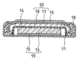
図1は本発明の蓄電デバイスの概略縦断面図である。図1に示すように、正極19は、正極集電体12と、少なくとも2電子以上が反応に関与する有機高分子化合物を活物質として含む正極合剤層13とからなる。セパレータ14は上記正極19上に配置され、必要に応じて電解質溶液が含まれる。負極20は、負極集電体17と、負極活物質を含む負極合剤層16とからなる。負極合剤層16と正極合剤層とが対向するように、負極20は、セパレータ14を介して、正極19上に配置される。負極20、セパレータ14、および正極19は、ケース11内に収納され、ケース11の開口端で、封口板15の周縁部をガスケット18を介してかしめることにより、ケース11内が密封されている。
The best mode for carrying out the present invention will be described below with reference to the drawings.
(Embodiment 1)
FIG. 1 is a schematic longitudinal sectional view of an electricity storage device of the present invention. As shown in FIG. 1, the
活物質には少なくとも2電子以上が反応に関与する有機高分子化合物を用いることができる。2電子以上が反応に関与する有機高分子化合物に、特に制限はないが、電極活性部位としてπ電子共役雲を有する有機高分子化合物などが挙げられる。
一般的に高分子化合物とは分子量10000以上の化合物を意味するが、本発明における有機高分子化合物とは、繰り返し結合単位(有機化合物からなるモノマー単位)を有する化合物であり、分子量が10000未満でも、繰り返し有機化合物からなるモノマー単位が結合して、重合体を形成しているものであればよい。
上記有機高分子化合物としては、例えば、以下に示す一般式(1)で表わされる、π電子共役雲を有する構造を含むものが挙げられる。
一般式(1):
As the active material, an organic polymer compound in which at least two electrons are involved in the reaction can be used. The organic polymer compound in which two or more electrons are involved in the reaction is not particularly limited, and examples thereof include an organic polymer compound having a π electron conjugated cloud as an electrode active site.
In general, a polymer compound means a compound having a molecular weight of 10,000 or more, but the organic polymer compound in the present invention is a compound having a repetitive bond unit (a monomer unit comprising an organic compound), even if the molecular weight is less than 10,000. Any monomer unit composed of repetitive organic compounds may be combined to form a polymer.
Examples of the organic polymer compound include those having a structure having a π electron conjugated cloud represented by the following general formula (1).
General formula (1):
式(1)中、Xは硫黄原子または酸素原子、R1〜R4はそれぞれ独立して鎖状の脂肪族基、環状の脂肪族基、水素原子、ヒドロキシル基、シアノ基、アミノ基、ニトロ基またはニトロソ基、R5およびR6はそれぞれ独立して水素原子、鎖状の脂肪族基または環状の脂肪族基であり、前記脂肪族基は水素原子、酸素原子、窒素原子、硫黄原子、ケイ素原子、リン原子、ホウ素原子およびハロゲン原子よりなる群から選ばれる少なくとも1種を含むことができる。 In the formula (1), X is a sulfur atom or an oxygen atom, R 1 to R 4 are each independently a chain aliphatic group, a cyclic aliphatic group, a hydrogen atom, a hydroxyl group, a cyano group, an amino group, a nitro group Group or nitroso group, R 5 and R 6 are each independently a hydrogen atom, a chain aliphatic group or a cyclic aliphatic group, and the aliphatic group is a hydrogen atom, an oxygen atom, a nitrogen atom, a sulfur atom, It can contain at least one selected from the group consisting of a silicon atom, a phosphorus atom, a boron atom and a halogen atom.
一般式(1)で表される化合物としては、例えば一般式(4)で表される化合物または化学式(5)で表される化合物が挙げられる。
一般式(4):
Examples of the compound represented by the general formula (1) include a compound represented by the general formula (4) or a compound represented by the chemical formula (5).
General formula (4):
式(4)中、R1〜R4およびR7〜R10はそれぞれ独立して鎖状の脂肪族基、環状の脂肪族基、水素原子、ヒドロキシル基、シアノ基、アミノ基、ニトロ基またはニトロソ基であり、前記脂肪族基は水素原子、酸素原子、窒素原子、硫黄原子、ケイ素原子、リン原子、ホウ素原子およびハロゲン原子の群から選ばれる少なくとも1種を含むことができる。
化学式(5):
In the formula (4), R 1 to R 4 and R 7 to R 10 are each independently a chain aliphatic group, a cyclic aliphatic group, a hydrogen atom, a hydroxyl group, a cyano group, an amino group, a nitro group or It is a nitroso group, and the aliphatic group may contain at least one selected from the group consisting of hydrogen atom, oxygen atom, nitrogen atom, sulfur atom, silicon atom, phosphorus atom, boron atom and halogen atom.
Chemical formula (5):
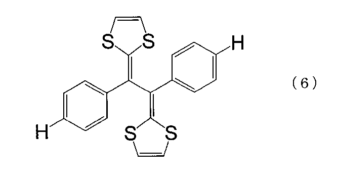
また、一般式(4)は、2つの5員環に位置された2つのベンゼン環の存在によって2つの5員環から電子が抜き取られるエネルギーレベルが接近し、あたかも1電子反応のように反応が進行する。したがって、反応速度が一般式(1)においてR5、R6がベンゼン環を含まない場合に比べて速くなる。一般式(4)の化合物の代表例としては、化学式(6)〜化学式(9)で表される化合物が好ましい化合物として挙げられる。
化学式(6):
In addition, in general formula (4), the energy levels at which electrons are extracted from two five-membered rings approach each other due to the presence of two benzene rings positioned in two five-membered rings, and the reaction is as if it were a one-electron reaction. proceed. Accordingly, the reaction rate is faster than in the case where R 5 and R 6 do not contain a benzene ring in the general formula (1). As typical examples of the compound of the general formula (4), compounds represented by the chemical formula (6) to the chemical formula (9) are preferable compounds.
Chemical formula (6):
化学式(7): Chemical formula (7):
化学式(8): Chemical formula (8):
化学式(9): Chemical formula (9):
上記一般式(5)で表される構造を含む有機高分子化合物としては、例えば、一般式(5)の化合物をポリアセチレンやポリメチルメタクリレートなどの別の高分子と結合された一般式(10)または一般式(11)で表される化合物が挙げられる。これらは、電解質溶液中での安定度が高い点で好ましい。
一般式(10):
Examples of the organic polymer compound having the structure represented by the general formula (5) include, for example, the general formula (10) in which the compound of the general formula (5) is combined with another polymer such as polyacetylene or polymethyl methacrylate. Or the compound represented by General formula (11) is mentioned. These are preferable in terms of high stability in the electrolyte solution.
General formula (10):
式(10)中、nは2以上の整数である。
一般式(11):
In formula (10), n is an integer of 2 or more.
General formula (11):
式(11)中、nは2以上の整数である。
また、上記有機高分子化合物としては、例えば、以下に示す一般式(2)で表わされる、π電子共役雲を有する構造を含むものが挙げられる。
一般式(2):
In formula (11), n is an integer of 2 or more.
Examples of the organic polymer compound include those containing a structure having a π-electron conjugated cloud represented by the following general formula (2).
General formula (2):
式(2)中、Xは窒素原子、R1〜R4はそれぞれ独立して鎖状の脂肪族基、環状の脂肪族基、水素原子、ヒドロキシル基、シアノ基、アミノ基、ニトロ基またはニトロソ基、R5およびR6はそれぞれ独立して水素原子、鎖状の脂肪族基または環状の脂肪族基であり、前記脂肪族基は水素原子、酸素原子、窒素原子、硫黄原子、ケイ素原子、リン原子、ホウ素原子およびハロゲン原子よりなる群から選ばれる少なくとも1種を含むことができる。
一般式(2)で表される化合物としては、例えば化学式(12)で表される化合物が挙げられる。
化学式(12):
In the formula (2), X is a nitrogen atom, and R 1 to R 4 are each independently a chain aliphatic group, a cyclic aliphatic group, a hydrogen atom, a hydroxyl group, a cyano group, an amino group, a nitro group, or a nitroso group. Groups R 5 and R 6 are each independently a hydrogen atom, a chain aliphatic group or a cyclic aliphatic group, and the aliphatic group is a hydrogen atom, an oxygen atom, a nitrogen atom, a sulfur atom, a silicon atom, It can contain at least one selected from the group consisting of phosphorus atom, boron atom and halogen atom.
Examples of the compound represented by the general formula (2) include a compound represented by the chemical formula (12).
Chemical formula (12):
上記有機高分子化合物としては、例えば、以下に示す一般式(3)で表わされる、π電子共役雲を有する構造を含むものが挙げられる。
一般式(3):
Examples of the organic polymer compound include those having a structure having a π-electron conjugated cloud represented by the following general formula (3).
General formula (3):
式(3)中、X1〜X4はそれぞれ独立して硫黄原子、酸素原子、セレン原子またはテルル原子、R1およびR2はそれぞれ独立して鎖状の脂肪族基または環状の脂肪族基であり、前記脂肪族基は酸素原子、窒素原子、硫黄原子、ケイ素原子、リン原子、およびホウ素原子よりなる群から選ばれる少なくとも1種を含むことができる。
一般式(3)で表される化合物としては、例えば一般式(13)〜(16)で表される化合物が挙げられる。
一般式(13):
In formula (3), X 1 to X 4 are each independently a sulfur atom, oxygen atom, selenium atom or tellurium atom, and R 1 and R 2 are each independently a chain aliphatic group or a cyclic aliphatic group. The aliphatic group may contain at least one selected from the group consisting of an oxygen atom, a nitrogen atom, a sulfur atom, a silicon atom, a phosphorus atom, and a boron atom.
Examples of the compound represented by the general formula (3) include compounds represented by the general formulas (13) to (16).
General formula (13):
式(13)中、X1〜X4はそれぞれ独立して硫黄原子、酸素原子、セレン原子またはテルル原子、R3およびR6はそれぞれ独立して鎖状の脂肪族基、環状の脂肪族基、水素原子、ヒドロキシル基、シアノ基、アミノ基、ニトロ基またはニトロソ基であり、前記脂肪族基は酸素原子、窒素原子、硫黄原子、ケイ素原子、リン原子、ホウ素原子およびハロゲン原子よりなる群から選ばれる少なくとも1種を含むことができる。
一般式(14):
In formula (13), X 1 to X 4 are each independently a sulfur atom, oxygen atom, selenium atom or tellurium atom, and R 3 and R 6 are each independently a chain aliphatic group or a cyclic aliphatic group. , A hydrogen atom, a hydroxyl group, a cyano group, an amino group, a nitro group or a nitroso group, and the aliphatic group is selected from the group consisting of an oxygen atom, a nitrogen atom, a sulfur atom, a silicon atom, a phosphorus atom, a boron atom and a halogen atom. It may contain at least one selected.
General formula (14):
式(14)中、X1〜X4はそれぞれ独立して硫黄原子、酸素原子、セレン原子、またはテルル原子、YおよびZはそれぞれ独立して硫黄原子、酸素原子、セレン原子、テルル原子またはメチレン基である。
一般式(15):
In formula (14), X 1 to X 4 are each independently a sulfur atom, oxygen atom, selenium atom, or tellurium atom, and Y and Z are each independently a sulfur atom, oxygen atom, selenium atom, tellurium atom, or methylene. It is a group.
Formula (15):
式(15)中、X1〜X4はそれぞれ独立して硫黄原子、酸素原子、セレン原子、またはテルル原子、R5およびR6はそれぞれ独立して鎖状の脂肪族基、環状の脂肪族基、水素原子、ヒドロキシル基、シアノ基、アミノ基、ニトロ基またはニトロソ基であり、前記脂肪族基は、酸素原子、窒素原子、イオウ原子、ケイ素原子、リン原子、ホウ素原子およびハロゲン原子よりなる群から選ばれる1種以上を含むことができ、nは1以上である。
一般式(16):
In formula (15), X 1 to X 4 are each independently a sulfur atom, oxygen atom, selenium atom, or tellurium atom, and R 5 and R 6 are each independently a chain aliphatic group or a cyclic aliphatic group. Group, hydrogen atom, hydroxyl group, cyano group, amino group, nitro group or nitroso group, and the aliphatic group consists of an oxygen atom, a nitrogen atom, a sulfur atom, a silicon atom, a phosphorus atom, a boron atom and a halogen atom 1 or more types chosen from a group can be included, and n is 1 or more.
Formula (16):
式(16)中、X1〜X4はそれぞれ独立して硫黄原子、酸素原子、セレン原子、またはテルル原子である。
また、一般式(3)で表される構造を含む有機高分子化合物としては、例えば、一般式(3)で表される化合物を側鎖に有する有機高分子化合物が挙げられる。このような有機高分子化合物としては、例えば主鎖骨格がポリビニルアルコールであり、側鎖がカルボキシテトラチアフルバレンである一般式(17)で表される化合物が挙げられる。
一般式(17):
In formula (16), X < 1 > -X < 4 > is a sulfur atom, an oxygen atom, a selenium atom, or a tellurium atom each independently.
Moreover, as an organic polymer compound containing the structure represented by General formula (3), the organic polymer compound which has the compound represented by General formula (3) in a side chain is mentioned, for example. Examples of such an organic polymer compound include a compound represented by the general formula (17) in which the main chain skeleton is polyvinyl alcohol and the side chain is carboxytetrathiafulvalene.
Formula (17):
式(17)中、nは2以上の整数である。
以上の種々の化合物を正極19に用いる形態では、正極合剤層13に電子伝導性を付与する目的で、カーボンブラック、グラファイト、アセチレンブラック等の炭素材料、ポリアニリン、ポリピロール、またはポリチオフェンなどの導電性高分子を正極合剤層13中に含ませてもよい。また、イオン導電性助剤として、ポリエチレンオキシドなどからなる固体電解質、またはポリメタクリル酸メチルなどからなるゲル電解質を正極合剤層13中に含ませてもよい。
In formula (17), n is an integer of 2 or more.
In the form in which the above various compounds are used for the
さらに、正極活物質の結着性を向上させるために、ポリフッ化ビニリデン、フッ化ビニリデン−ヘキサフルオロプロピレン共重合体、フッ化ビニリデン−ポリテトラフルオロエチレン、ポリエチレン、ポリイミド、ポリアクリル酸などのバインダーを正極合剤層中に含ませてもよい。
集電体には、一般の電池と同様、金属箔、金属メッシュ、導電性フィラーを含む樹脂フィルムなどが用いられる。
Furthermore, in order to improve the binding property of the positive electrode active material, a binder such as polyvinylidene fluoride, vinylidene fluoride-hexafluoropropylene copolymer, vinylidene fluoride-polytetrafluoroethylene, polyethylene, polyimide, polyacrylic acid or the like is added. You may include in a positive mix layer.
As the current collector, a metal foil, a metal mesh, a resin film containing a conductive filler, or the like is used as in a general battery.
電解質は、電解質を含む溶液、さらに上記電解質溶液をポリアクリロニトリル、アクリレートモノマーあるいはメタクリレートモノマーを含む重合体、エチレンとアクリロニトリルの共重合体を用いてゲル化されたポリマー電解質、あるいは固体電解質として用いられる。電解質溶液の場合は電解質溶液をセパレータに含浸させて使用するのが好ましい。 The electrolyte is used as a solution containing an electrolyte, and the electrolyte solution is a polymer electrolyte containing polyacrylonitrile, an acrylate monomer or a methacrylate monomer, a polymer electrolyte gelled with a copolymer of ethylene and acrylonitrile, or a solid electrolyte. In the case of an electrolyte solution, it is preferable to impregnate the separator with the electrolyte solution.
電解質は、リチウムイオン電池や非水系電気二重層キャパシタに使用可能なものであればよい。具体的には、以下に挙げるカチオンとアニオンの組み合わせにより形成される塩を用いることができる。カチオン種としては、リチウム、ナトリウム、カリウムなどのアルカリ金属カチオンやマグネシウムなどのアルカリ土類金属カチオン、テトラエチルアンモニウムや1、3−エチルメチルイミダゾリウムに代表される4級アンモニウムカチオンを用いることができる。アニオン種としては、ハロゲン化物アニオン、過塩素酸アニオンおよびトリフルオロメタンスルホン酸アニオン、四ホウフッ化物アニオン、トリフルオロリン6フッ化物アニオン、トリフルオロメタンスルホン酸アニオン、ビス(トリフルオロメタンスルホニル)イミドアニオン、ビス(パーフルオロエチルスルホニル)イミドアニオン、などが挙げられる。これらは単独あるいは混合して用いることができる。 The electrolyte may be any electrolyte that can be used for lithium ion batteries and non-aqueous electric double layer capacitors. Specifically, salts formed by combinations of cations and anions listed below can be used. As the cation species, alkali metal cations such as lithium, sodium and potassium, alkaline earth metal cations such as magnesium, quaternary ammonium cations such as tetraethylammonium and 1,3-ethylmethylimidazolium can be used. Anionic species include halide anions, perchlorate anions and trifluoromethanesulfonate anions, tetraborofluoride anions, trifluorophosphoric hexafluoride anions, trifluoromethanesulfonate anions, bis (trifluoromethanesulfonyl) imide anions, bis (per Fluoroethylsulfonyl) imide anion, and the like. These can be used alone or in combination.
電解質自身が溶液状である場合、必ずしもそれらを溶媒と混合しなくとも、単独で用いることも可能である。電解質自身が固体である場合、以下に挙げるような溶媒に溶解させて用いることが必要である。
電解質溶液を形成する溶媒は、リチウムイオン電池や非水系電気二重層キャパシタに使用可能なものであればよい。具体的には、エチレンカーボネート、プロピレンカーボネート、ジメチルカーボネート、ジエチルカーボネート、メチルエチルカーボネート、γブチルラクトン、テトラヒドロフラン、ジオキソラン、スルホラン、ジメチルホルムアミド、アセトニトリル等の非水溶媒が好ましい。これらは単独あるいは混合して用いることができる。
When the electrolyte itself is in the form of a solution, it can be used alone without necessarily mixing it with a solvent. When the electrolyte itself is solid, it is necessary to use it by dissolving it in the following solvent.
The solvent for forming the electrolyte solution may be any solvent that can be used for lithium ion batteries and non-aqueous electric double layer capacitors. Specifically, nonaqueous solvents such as ethylene carbonate, propylene carbonate, dimethyl carbonate, diethyl carbonate, methyl ethyl carbonate, γ-butyl lactone, tetrahydrofuran, dioxolane, sulfolane, dimethylformamide, and acetonitrile are preferable. These can be used alone or in combination.
固体電解質には、Li2S−SiS2、Li2S−B2S5、Li2S−P2S5−GeS2、ナトリウム/アルミナ(Al2O3)無定形または低相転移温度(Tg)のポリエーテル、無定形フッ化ビニリデン−6フッ化プロピレンコポリマー、異種高分子ブレンド体ポリエチレンオキサイドなどが挙げられる。 Solid electrolytes include Li 2 S—SiS 2 , Li 2 S—B 2 S 5 , Li 2 S—P 2 S 5 —GeS 2 , sodium / alumina (Al 2 O 3 ) amorphous or low phase transition temperature ( Tg) polyether, amorphous vinylidene fluoride-6-fluoropropylene copolymer, heterogeneous polymer blend polyethylene oxide and the like.
負極活物質は、特に制限はないが、グラファイト、非晶質炭素などの炭素材料、リチウム金属、リチウム含有複合窒化物、リチウム含有チタン酸化物、スズと炭素の複合物、スズと他の金属との複合物、シリコン、シリコン酸化物、および活性炭などの電気二重層容量を有する炭素材料などを用いることができる。 The negative electrode active material is not particularly limited, but carbon materials such as graphite and amorphous carbon, lithium metal, lithium-containing composite nitride, lithium-containing titanium oxide, a composite of tin and carbon, tin and other metals And carbon materials having electric double layer capacity such as silicon, silicon oxide, and activated carbon can be used.
次に、本発明における蓄電デバイスの充放電制御方法において、正極活物質の容量利用率90%以下となるように蓄電デバイスを充放電することにより得られる効果を説明する。
なお、ここでいう容量とは電流容量を意味し、容量利用率とは、電極中に含まれる活物質の重量に基づいて算出される理論容量に対して実際に充放電反応で使用する容量の割合を意味する。活物質の理論容量は、高分子繰り返し単位あたりの反応電子数(n)、高分子の繰り返し単位の分子量(Mw)に対して次式により求められる。
理論容量(mAh/g)=(n×96500/Mw)×(1000/3600)
Next, the effect obtained by charging / discharging the electricity storage device so that the capacity utilization of the positive electrode active material is 90% or less in the method for controlling charge / discharge of the electricity storage device in the present invention will be described.
The capacity here means current capacity, and the capacity utilization is the capacity actually used in the charge / discharge reaction with respect to the theoretical capacity calculated based on the weight of the active material contained in the electrode. Mean percentage. The theoretical capacity of the active material is determined by the following equation with respect to the number of reaction electrons per polymer repeating unit (n) and the molecular weight (Mw) of the polymer repeating unit.
Theoretical capacity (mAh / g) = (n × 96500 / Mw) × (1000/3600)
一般式(17)で表される有機高分子化合物を正極活物質に用いた場合について以下に説明する。一般式(3)で表される低分子材料としてテトラチアフルバレンを活物質に用いた時は、充放電反応に伴う活物質の溶出により繰り返し充放電試験によって容量劣化する事が確認されているが、このような高分子化合物を活物質に用いることで、活物質の溶解による容量低下が抑制されるということを確認している。しかしながら、活物質の溶解以外の他の劣化要因により容量劣化が生じるという傾向が確認されている。本発明者らの研究の結果、高電位状態で酸化還元反応を繰り返すことによる劣化が生じるという知見が得られ、90%以下の容量利用率で蓄電デバイスを利用することにより容量低下が顕著に抑制されることを見出した。 The case where the organic high molecular compound represented by General formula (17) is used for a positive electrode active material is demonstrated below. When tetrathiafulvalene is used as an active material as the low molecular weight material represented by the general formula (3), it has been confirmed that capacity degradation is caused by repeated charge / discharge tests due to elution of the active material accompanying the charge / discharge reaction. It has been confirmed that the use of such a polymer compound as an active material suppresses a decrease in capacity due to dissolution of the active material. However, a tendency has been confirmed that capacity deterioration occurs due to deterioration factors other than dissolution of the active material. As a result of the study by the present inventors, the knowledge that deterioration due to repeated oxidation-reduction reaction in a high potential state is obtained, and the capacity reduction is remarkably suppressed by using the electricity storage device at a capacity utilization rate of 90% or less. I found out that
(実施の形態2)
本実施の形態における蓄電デバイスの充放電制御方法は、繰り返し単位あたりに少なくとも2電子以上が関与する多電子反応の反応機構を有する有機高分子化合物を正極活物質に用いる蓄電デバイスにおいて、正極容量に対する負極容量の割合を90%以下とする。
負極容量を正極容量に対して90%以下とすると、必然的に負極容量により蓄電デバイスの容量が規制されることになる。このため、本実施の形態では、正極の容量利用率が90%以下に制限されることになり、実施の形態1と同様に容量低下を抑制することが可能となる。
(Embodiment 2)
The charge / discharge control method for an electricity storage device according to the present embodiment is a storage device using an organic polymer compound having a reaction mechanism of a multi-electron reaction involving at least two electrons per repeating unit as a positive electrode active material. The proportion of the negative electrode capacity is 90% or less.
When the negative electrode capacity is 90% or less with respect to the positive electrode capacity, the capacity of the electric storage device is inevitably regulated by the negative electrode capacity. For this reason, in this Embodiment, the capacity utilization factor of a positive electrode will be restrict | limited to 90% or less, and it becomes possible to suppress a capacity | capacitance fall similarly to Embodiment 1. FIG.
(実施の形態3)
本実施の形態における蓄電デバイスの充放電制御方法は、少なくとも2電子以上が関与する多電子反応の反応機構を有する有機高分子化合物を正極活物質に用いる蓄電デバイスにおいて、充電時の上限電圧を充電電圧曲線の最高反応電圧以下に設定する。
充電時の最高反応電圧とは、充電時の電圧曲線が複数段の平坦部を有する場合、充電電圧曲線において最も高い電圧側に位置する平坦部の電圧を意味する。そして、充電時の上限電圧を最高反応電圧以下に設定することにより、活物質の酸化状態を制御することが可能となる。
(Embodiment 3)
The charge / discharge control method for an electricity storage device in the present embodiment charges an upper limit voltage during charging in an electricity storage device using an organic polymer compound having a reaction mechanism of a multi-electron reaction involving at least two electrons as a positive electrode active material. Set it below the maximum reaction voltage of the voltage curve.
The maximum reaction voltage at the time of charging means the voltage of the flat part located on the highest voltage side in the charging voltage curve when the voltage curve at the time of charging has a plurality of flat parts. And it becomes possible to control the oxidation state of an active material by setting the upper limit voltage at the time of charge to below the maximum reaction voltage.
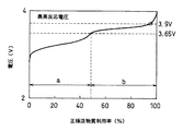
ここで、図2は主鎖がポリエチレンオキサイド骨格で、カルボキシル基を介して側鎖にテトラチアフルバレン骨格を有する一般式(17)で表される高分子化合物を正極活物質に用い、負極活物質にLiを用いた時の充電電圧曲線である。正極活物質にこのような有機高分子化合物を用いた場合、充電電圧曲線は2段の平坦部(領域aおよびbに存在する平坦部)を有する。低電圧領域(図2中の領域a)では0価から1価の反応が進行し、高電圧領域(図2中の領域b)では1価から2価となる反応が進行すると考えられる。 Here, in FIG. 2, a polymer compound represented by the general formula (17) having a polyethylene oxide skeleton as a main chain and a tetrathiafulvalene skeleton as a side chain via a carboxyl group is used as a positive electrode active material. It is a charging voltage curve when Li is used for. When such an organic polymer compound is used for the positive electrode active material, the charging voltage curve has two flat portions (flat portions existing in the regions a and b). It is considered that the reaction from 0 to 1 valence proceeds in the low voltage region (region a in FIG. 2), and the reaction from 1 to 2 valence proceeds in the high voltage region (region b in FIG. 2).
例えば、図2に示す充電電圧曲線の最高反応電圧は、領域bの平坦部(図2中の3.65〜3.9V)のように平坦部が傾いている場合、領域bの平坦部において高電圧側に位置する3.9V付近の電圧である。そして、2つの平坦部の変極点付近に位置する3.5Vの電圧を上限電圧に設定することにより、活物質の酸化状態を1価に制限することが可能となり、充放電サイクルにともなう容量低下を抑制すること可能となる。
以下に本発明の実施例を詳細に示すが、本発明はこれらの実施例に限定されない。
For example, the maximum reaction voltage of the charging voltage curve shown in FIG. 2 is such that when the flat portion is inclined like the flat portion of the region b (3.65 to 3.9 V in FIG. 2), the flat portion of the region b It is a voltage near 3.9 V located on the high voltage side. And, by setting the voltage of 3.5V located near the inflection point of the two flat portions as the upper limit voltage, it becomes possible to limit the oxidation state of the active material to monovalent, and the capacity reduction accompanying the charge / discharge cycle Can be suppressed.
Examples of the present invention will be described in detail below, but the present invention is not limited to these examples.
《実施例1》
(1)正極の作製
正極活物質として、上記の一般式(17)(数平均分子量:4050)で表される有機化合物を用いた。上記化合物はポリビニルアルコール(Aldrich社製)とカルボキシテトラチアフルバレンを脱水縮合により反応させて合成した。上記化合物30mgとアセチレンブラック30mgとを均一に混合し、さらにN−メチル−2−ピロリドンを1mg加えてスラリーを得た。次に上記スラリーにポリフッ化ビニリデン5mgを加えて混合し、スラリー状の正極合剤を得た。さらに上記正極合剤を、正極集電板12としてアルミニウム箔の上に塗布し、真空乾燥した後、これを直径13.5mmの円盤状に打ち抜き裁断して、正極集電板12上に正極合剤層13が形成された正極19を作製した。このとき、正極活物質の塗布重量は、単位面積あたり1.7mg/cm2であった。
Example 1
(1) Production of positive electrode As the positive electrode active material, an organic compound represented by the above general formula (17) (number average molecular weight: 4050) was used. The above compound was synthesized by reacting polyvinyl alcohol (Aldrich) and carboxytetrathiafulvalene by dehydration condensation. 30 mg of the above compound and 30 mg of acetylene black were uniformly mixed, and 1 mg of N-methyl-2-pyrrolidone was further added to obtain a slurry. Next, 5 mg of polyvinylidene fluoride was added to the slurry and mixed to obtain a slurry-like positive electrode mixture. Further, the above positive electrode mixture was applied as a positive electrode
(2)負極の作製
負極活物質として粉状グラファイト15mgと、アセチレンブラック6mgとを均一に混合し、さらにポリビニルピロリドン6mgおよびメタノール250gを加えてスラリーを得た。このスラリー状の負極合剤を負極集電板17としてアルミニウム箔の上にキャストし、真空乾燥を行い、これを直径13.5mmの円盤状に打ち抜き裁断して、負極集電板17上に負極合剤層16が形成された負極20を作製した。
(2) Production of Negative Electrode As a negative electrode active material, 15 mg of powdery graphite and 6 mg of acetylene black were uniformly mixed, and 6 mg of polyvinylpyrrolidone and 250 g of methanol were further added to obtain a slurry. This slurry-like negative electrode mixture is cast on an aluminum foil as a negative electrode
(3)蓄電池デバイスの作製
セパレータ14には、多孔質ポリエチレンシートを用いた。電解液には、エチレンカーボネートとエチルメチルカーボネートとを重量比1:1で混合した混合溶媒中に1Mの濃度でホウフッ化リチウムを溶解させたものを用いた。比較しやすいように本実施例では充放電サイクルにおける容量低下が大きい電解液を選択した。上記の正極、負極、セパレータ、電解液を用いて、上記の図1と同じコイン型蓄電デバイスを得た。
上記の負極作製において、キャスト時の厚さを制御することにより、容量の異なる負極を作成し、正極容量に対する負極容量を30%、50%、70%及び90%と変えて、それぞれ負極20を作製した。そして、正極容量に対する負極容量が30%、50%、70%、90%となるサンプルを作製しサンプル1、2、3および4とした。また比較例として正極容量に対する負極容量が100、150%である負極を用いたコイン型蓄電デバイスを作製し、サンプルAおよびBとした。
(3) Production of Storage Battery Device A porous polyethylene sheet was used for the
In the above negative electrode production, negative electrodes having different capacities were prepared by controlling the thickness at the time of casting, and the negative electrode capacity with respect to the positive electrode capacity was changed to 30%, 50%, 70% and 90%, respectively. Produced. Samples having negative electrode capacities of 30%, 50%, 70%, and 90% with respect to the positive electrode capacities were produced as
上記で得られた各蓄電デバイスについて充放電サイクル試験を行った。試験条件は、充放電電流値0.5mA、充電時の上限電圧4.0V、放電時の下限電圧3.0Vとした。各蓄電デバイスについて、充放電を500サイクル行い、初回、50、100、300、500サイクル時の正極活物質あたりの充電容量維持率を調べた。容量維持率は、サンプルAの初期容量に対する割合を百分率で表した。試験結果を表1に示す。 A charge / discharge cycle test was performed on each power storage device obtained above. The test conditions were a charge / discharge current value of 0.5 mA, an upper limit voltage of 4.0 V during charging, and a lower limit voltage of 3.0 V during discharge. About each electrical storage device, charging / discharging was performed 500 cycles, and the charge capacity maintenance rate per positive electrode active material at the time of the first, 50, 100, 300, 500 cycles was investigated. The capacity retention rate was expressed as a percentage of the initial capacity of sample A. The test results are shown in Table 1.
表1から、負極容量が正極容量の90%以下であるときには良好なサイクル特性を示すが、正極容量の100%を超えて使用すると、サイクル劣化が早いことが確認された。 Table 1 shows that good cycle characteristics are exhibited when the negative electrode capacity is 90% or less of the positive electrode capacity, but it was confirmed that the cycle deterioration was rapid when used exceeding 100% of the positive electrode capacity.
《実施例2》
負極として、実施例1で使用した正極容量に対して150%の容量を有する負極を用いて実施例1と同様の方法により蓄電デバイスを作製した。上記で得られた蓄電デバイスに関して、充放電電流値1mA、放電時の下限電圧3.0V、充電時の上限電圧3.65Vまたは3.8Vとして充放電サイクル試験を行い、それぞれサンプル5および6とした。また、比較例として充電時の上限電圧を4.0Vとした以外は上記と同じ条件で充放電サイクル試験を行い、サンプルCとした。試験結果を表2に示す。
Example 2
Using the negative electrode having a capacity of 150% of the positive electrode capacity used in Example 1 as the negative electrode, an electricity storage device was produced in the same manner as in Example 1. Regarding the electricity storage device obtained above, a charge / discharge cycle test was conducted with a charge / discharge current value of 1 mA, a lower limit voltage of 3.0 V during discharge, and an upper limit voltage of 3.65 V or 3.8 V during charge. did. In addition, as a comparative example, a charge / discharge cycle test was performed under the same conditions as described above except that the upper limit voltage during charging was set to 4.0 V, and Sample C was obtained. The test results are shown in Table 2.
表2から充電時の上限電圧を変更することにより、活物質の利用率を制御することが可能であり、正極活物質の利用率が80%以下であれば容量低下が抑制され、充放電サイクル特性が向上することがわかった。 By changing the upper limit voltage during charging from Table 2, it is possible to control the utilization factor of the active material, and if the utilization factor of the positive electrode active material is 80% or less, the capacity reduction is suppressed, and the charge / discharge cycle It was found that the characteristics were improved.
本発明の蓄電デバイスの充放電制御方法は、リチウムイオン電池や電気二重層キャパシタに好適に用いることができる。 The charge / discharge control method for an electricity storage device of the present invention can be suitably used for a lithium ion battery or an electric double layer capacitor.
11 ケース
12 正極集電体
13 正極合剤層
14 セパレータ
15 封口板
16 負極合剤層
17 負極集電体
18 ガスケット
19 正極
20 負極
DESCRIPTION OF
Claims (6)
電解質;
集電体と、前記集電体の表面に形成された、導電材および少なくとも2電子以上が関与する多電子反応の反応機構を有する有機高分子化合物を正極活物質として含む合剤層と、を含む正極;
を有する蓄電デバイスの充放電制御方法であって、
前記正極活物質の容量利用率が90%以下となるように前記蓄電デバイスを充放電すること、を特徴とする蓄電デバイスの充放電制御方法。 A negative electrode having a negative electrode active material;
Electrolytes;
A current collector, and a mixture layer formed on a surface of the current collector as a positive electrode active material, comprising a conductive material and an organic polymer compound having a multi-electron reaction reaction mechanism involving at least two electrons. A positive electrode containing;
A charge / discharge control method for an electricity storage device comprising:
A charge / discharge control method for an electricity storage device, wherein the electricity storage device is charged / discharged so that a capacity utilization of the positive electrode active material is 90% or less.
を特徴とする請求項1に記載の蓄電デバイスの充放電制御方法。 The negative electrode capacity of the negative electrode relative to the positive electrode capacity of the positive electrode is 90% or less,
The charging / discharging control method of the electrical storage device of Claim 1 characterized by these.
を特徴とする請求項1記載の蓄電デバイスの充放電制御方法。 Set the upper limit voltage during charging to the maximum reaction voltage of the charging voltage curve,
The charging / discharging control method of the electrical storage device of Claim 1 characterized by these.
を特徴とする請求項1に記載の蓄電デバイスの充放電制御方法。 The organic polymer compound has a π-electron conjugated cloud in the molecule;
The charging / discharging control method of the electrical storage device of Claim 1 characterized by these.
を特徴とする請求項1〜4のいずれかに記載の蓄電デバイスの充放電制御方法。
一般式(1):
一般式(2):
The charging / discharging control method of the electrical storage device in any one of Claims 1-4 characterized by these.
General formula (1):
General formula (2):
を特徴とする請求項1〜4のいずれかに記載の蓄電デバイスの充放電制御方法。
一般式(3):
The charging / discharging control method of the electrical storage device in any one of Claims 1-4 characterized by these.
General formula (3):
Priority Applications (1)
| Application Number | Priority Date | Filing Date | Title |
|---|---|---|---|
| JP2006133732A JP5036214B2 (en) | 2006-05-12 | 2006-05-12 | Charge / discharge control method for power storage device |
Applications Claiming Priority (1)
| Application Number | Priority Date | Filing Date | Title |
|---|---|---|---|
| JP2006133732A JP5036214B2 (en) | 2006-05-12 | 2006-05-12 | Charge / discharge control method for power storage device |
Publications (2)
| Publication Number | Publication Date |
|---|---|
| JP2007305461A true JP2007305461A (en) | 2007-11-22 |
| JP5036214B2 JP5036214B2 (en) | 2012-09-26 |
Family
ID=38839215
Family Applications (1)
| Application Number | Title | Priority Date | Filing Date |
|---|---|---|---|
| JP2006133732A Expired - Fee Related JP5036214B2 (en) | 2006-05-12 | 2006-05-12 | Charge / discharge control method for power storage device |
Country Status (1)
| Country | Link |
|---|---|
| JP (1) | JP5036214B2 (en) |
Cited By (9)
| Publication number | Priority date | Publication date | Assignee | Title |
|---|---|---|---|---|
| JP2009295397A (en) * | 2008-06-04 | 2009-12-17 | Denso Corp | Organic radical secondary battery, charge/discharge control method of the organic radical secondary battery, and charge/discharge control device of the organic radical secondary battery |
| WO2009157206A1 (en) * | 2008-06-25 | 2009-12-30 | パナソニック株式会社 | Electricity storage material and electricity storage device |
| JP2010118320A (en) * | 2008-11-14 | 2010-05-27 | Denso Corp | Secondary battery |
| EP2306562A1 (en) * | 2008-07-31 | 2011-04-06 | Panasonic Corporation | Accumulator material and accumulator device |
| JP2011103208A (en) * | 2009-11-10 | 2011-05-26 | Denso Corp | Secondary battery |
| WO2011077754A1 (en) | 2009-12-24 | 2011-06-30 | パナソニック株式会社 | Electrode and electricity storage device |
| WO2011099311A1 (en) | 2010-02-15 | 2011-08-18 | パナソニック株式会社 | Electrode active material for electrical storage device, electrical storage device, electronic device, and transport device |
| JP2014029898A (en) * | 2012-07-31 | 2014-02-13 | Taiyo Yuden Co Ltd | Electrochemical capacitor |
| JP2017181236A (en) * | 2016-03-30 | 2017-10-05 | 三洋化成工業株式会社 | Arm-worn electronic device and contactless charging system |
Citations (8)
| Publication number | Priority date | Publication date | Assignee | Title |
|---|---|---|---|---|
| JPS62184779A (en) * | 1986-02-06 | 1987-08-13 | Bridgestone Corp | Charging method for secondary battery |
| JPH01294375A (en) * | 1988-05-20 | 1989-11-28 | Hitachi Maxell Ltd | Charging/discharging method for lithium secondary battery |
| JPH06189466A (en) * | 1992-12-18 | 1994-07-08 | Hitachi Ltd | Secondary battery system and its charging method |
| JP2000228199A (en) * | 1999-02-09 | 2000-08-15 | Toyota Central Res & Dev Lab Inc | Nonaqueous electrolyte solution secondary battery |
| JP2002042867A (en) * | 2000-07-31 | 2002-02-08 | Sanyo Electric Co Ltd | Lithium ion secondary battery |
| JP2003007349A (en) * | 2001-06-22 | 2003-01-10 | Sony Corp | Charging method for battery |
| JP2004111374A (en) * | 2002-08-29 | 2004-04-08 | Matsushita Electric Ind Co Ltd | Electrochemical device |
| JP2004227931A (en) * | 2003-01-23 | 2004-08-12 | Matsushita Electric Ind Co Ltd | Nonaqueous electrolyte rechargeable battery |
-
2006
- 2006-05-12 JP JP2006133732A patent/JP5036214B2/en not_active Expired - Fee Related
Patent Citations (8)
| Publication number | Priority date | Publication date | Assignee | Title |
|---|---|---|---|---|
| JPS62184779A (en) * | 1986-02-06 | 1987-08-13 | Bridgestone Corp | Charging method for secondary battery |
| JPH01294375A (en) * | 1988-05-20 | 1989-11-28 | Hitachi Maxell Ltd | Charging/discharging method for lithium secondary battery |
| JPH06189466A (en) * | 1992-12-18 | 1994-07-08 | Hitachi Ltd | Secondary battery system and its charging method |
| JP2000228199A (en) * | 1999-02-09 | 2000-08-15 | Toyota Central Res & Dev Lab Inc | Nonaqueous electrolyte solution secondary battery |
| JP2002042867A (en) * | 2000-07-31 | 2002-02-08 | Sanyo Electric Co Ltd | Lithium ion secondary battery |
| JP2003007349A (en) * | 2001-06-22 | 2003-01-10 | Sony Corp | Charging method for battery |
| JP2004111374A (en) * | 2002-08-29 | 2004-04-08 | Matsushita Electric Ind Co Ltd | Electrochemical device |
| JP2004227931A (en) * | 2003-01-23 | 2004-08-12 | Matsushita Electric Ind Co Ltd | Nonaqueous electrolyte rechargeable battery |
Cited By (15)
| Publication number | Priority date | Publication date | Assignee | Title |
|---|---|---|---|---|
| JP2009295397A (en) * | 2008-06-04 | 2009-12-17 | Denso Corp | Organic radical secondary battery, charge/discharge control method of the organic radical secondary battery, and charge/discharge control device of the organic radical secondary battery |
| WO2009157206A1 (en) * | 2008-06-25 | 2009-12-30 | パナソニック株式会社 | Electricity storage material and electricity storage device |
| US8551652B2 (en) | 2008-06-25 | 2013-10-08 | Panasonic Corporation | Electricity storage material and electricity storage device |
| US8945769B2 (en) | 2008-07-31 | 2015-02-03 | Panasonic Corporation | Accumulator material and accumulator device |
| EP2306562A1 (en) * | 2008-07-31 | 2011-04-06 | Panasonic Corporation | Accumulator material and accumulator device |
| EP2306562A4 (en) * | 2008-07-31 | 2013-11-27 | Panasonic Corp | Accumulator material and accumulator device |
| JP2010118320A (en) * | 2008-11-14 | 2010-05-27 | Denso Corp | Secondary battery |
| JP2011103208A (en) * | 2009-11-10 | 2011-05-26 | Denso Corp | Secondary battery |
| WO2011077754A1 (en) | 2009-12-24 | 2011-06-30 | パナソニック株式会社 | Electrode and electricity storage device |
| US9640335B2 (en) | 2009-12-24 | 2017-05-02 | Panasonic Corporation | Electrode and electricity storage device |
| WO2011099311A1 (en) | 2010-02-15 | 2011-08-18 | パナソニック株式会社 | Electrode active material for electrical storage device, electrical storage device, electronic device, and transport device |
| EP2482370A4 (en) * | 2010-02-15 | 2016-08-17 | Panasonic Corp | Electrode active material for electrical storage device, electrical storage device, electronic device, and transport device |
| US9650392B2 (en) | 2010-02-15 | 2017-05-16 | Panasonic Corporation | Electrode active material for power storage device, power storage device, and electronic and transportation device |
| JP2014029898A (en) * | 2012-07-31 | 2014-02-13 | Taiyo Yuden Co Ltd | Electrochemical capacitor |
| JP2017181236A (en) * | 2016-03-30 | 2017-10-05 | 三洋化成工業株式会社 | Arm-worn electronic device and contactless charging system |
Also Published As
| Publication number | Publication date |
|---|---|
| JP5036214B2 (en) | 2012-09-26 |
Similar Documents
| Publication | Publication Date | Title |
|---|---|---|
| JP5036214B2 (en) | Charge / discharge control method for power storage device | |
| JP4047372B2 (en) | Method for producing secondary battery and method for preparing positive electrode active material for secondary battery | |
| JP6355163B2 (en) | Lithium ion battery | |
| JP2007281107A (en) | Electricity storage device | |
| US8034484B2 (en) | Electrochemical device and electrode active material for electrochemical device | |
| JP6355488B2 (en) | Halogen secondary battery | |
| JP5191931B2 (en) | Lithium secondary battery using ionic liquid | |
| CN104956536B (en) | Lithium secondary battery | |
| JP2006324179A (en) | Electrode and electrochemical element using it | |
| JP2007227136A (en) | Power storage device | |
| JP2007305430A (en) | Electrochemical element | |
| JP2006252917A (en) | Lithium-ion secondary battery | |
| JP2008235249A (en) | Electrode for secondary battery and method for making same, and secondary battery using this electrode | |
| JP2004342605A (en) | Electrochemical element and electrode active material for electrochemical element | |
| KR20090063615A (en) | Organic electrolytic solution and lithium battery employing the same | |
| KR101356393B1 (en) | A positive electrode for lithium-sulfur battery, and lithium-sulfur battery comprising the same | |
| JP5110625B2 (en) | Electricity storage device | |
| JP2008159275A (en) | Electrode active material and power storage device using the same | |
| JP5818689B2 (en) | Lithium ion secondary battery | |
| JP2007265712A (en) | Electrode and storage element using it | |
| JP4901089B2 (en) | Nonaqueous electrolyte secondary battery | |
| JP6465630B2 (en) | Secondary battery and method for manufacturing secondary battery | |
| JP2006073253A (en) | Nonaqueous electrolyte battery | |
| JP2008288022A (en) | Electrode active material for energy storage device, and energy storage device | |
| JP2002313416A (en) | Non-aqueous electrolyte secondary battery |
Legal Events
| Date | Code | Title | Description |
|---|---|---|---|
| A621 | Written request for application examination |
Free format text: JAPANESE INTERMEDIATE CODE: A621 Effective date: 20090218 |
|
| A977 | Report on retrieval |
Free format text: JAPANESE INTERMEDIATE CODE: A971007 Effective date: 20120209 |
|
| A131 | Notification of reasons for refusal |
Free format text: JAPANESE INTERMEDIATE CODE: A131 Effective date: 20120308 |
|
| A521 | Written amendment |
Free format text: JAPANESE INTERMEDIATE CODE: A523 Effective date: 20120423 |
|
| TRDD | Decision of grant or rejection written | ||
| A01 | Written decision to grant a patent or to grant a registration (utility model) |
Free format text: JAPANESE INTERMEDIATE CODE: A01 Effective date: 20120607 |
|
| A01 | Written decision to grant a patent or to grant a registration (utility model) |
Free format text: JAPANESE INTERMEDIATE CODE: A01 |
|
| A61 | First payment of annual fees (during grant procedure) |
Free format text: JAPANESE INTERMEDIATE CODE: A61 Effective date: 20120703 |
|
| FPAY | Renewal fee payment (event date is renewal date of database) |
Free format text: PAYMENT UNTIL: 20150713 Year of fee payment: 3 |
|
| R150 | Certificate of patent or registration of utility model |
Free format text: JAPANESE INTERMEDIATE CODE: R150 |
|
| LAPS | Cancellation because of no payment of annual fees |