JP2007302300A - Cap feeding device - Google Patents
Cap feeding device Download PDFInfo
- Publication number
- JP2007302300A JP2007302300A JP2006132493A JP2006132493A JP2007302300A JP 2007302300 A JP2007302300 A JP 2007302300A JP 2006132493 A JP2006132493 A JP 2006132493A JP 2006132493 A JP2006132493 A JP 2006132493A JP 2007302300 A JP2007302300 A JP 2007302300A
- Authority
- JP
- Japan
- Prior art keywords
- cap
- supply device
- caps
- unit
- cap supply
- Prior art date
- Legal status (The legal status is an assumption and is not a legal conclusion. Google has not performed a legal analysis and makes no representation as to the accuracy of the status listed.)
- Pending
Links
Images


Classifications
-
- B—PERFORMING OPERATIONS; TRANSPORTING
- B67—OPENING, CLOSING OR CLEANING BOTTLES, JARS OR SIMILAR CONTAINERS; LIQUID HANDLING
- B67B—APPLYING CLOSURE MEMBERS TO BOTTLES JARS, OR SIMILAR CONTAINERS; OPENING CLOSED CONTAINERS
- B67B3/00—Closing bottles, jars or similar containers by applying caps
- B67B3/02—Closing bottles, jars or similar containers by applying caps by applying flanged caps, e.g. crown caps, and securing by deformation of flanges
- B67B3/06—Feeding caps to capping heads
- B67B3/064—Feeding caps to capping heads from a hopper
-
- B—PERFORMING OPERATIONS; TRANSPORTING
- B65—CONVEYING; PACKING; STORING; HANDLING THIN OR FILAMENTARY MATERIAL
- B65B—MACHINES, APPARATUS OR DEVICES FOR, OR METHODS OF, PACKAGING ARTICLES OR MATERIALS; UNPACKING
- B65B5/00—Packaging individual articles in containers or receptacles, e.g. bags, sacks, boxes, cartons, cans, jars
- B65B5/10—Filling containers or receptacles progressively or in stages by introducing successive articles, or layers of articles
- B65B5/101—Filling containers or receptacles progressively or in stages by introducing successive articles, or layers of articles by gravity
- B65B5/103—Filling containers or receptacles progressively or in stages by introducing successive articles, or layers of articles by gravity for packaging pills or tablets
Abstract
Description
本発明は、処方に応じて錠剤をバイアル瓶に充填する錠剤充填装置におけるキャップ供給装置に関する。 The present invention relates to a cap supply device in a tablet filling device that fills a vial with a tablet according to a prescription.
従来、バイアル瓶には、薬剤を収容された後、キャップによって閉鎖されている(例えば、特許文献1,2参照)。
Conventionally, after a medicine is stored in a vial, it is closed with a cap (for example, see
バイアル瓶をキャップで閉鎖するキャッピング装置にキャップを供給するための装置としては、キャップの向きを全て同じ方向に向かわせるために、バイブレータで振動を与えてキャップを1つずつ供給可能とし、かつ、姿勢制御手段で、キャップを同一方向に向かうように方向変換する構成のものや(例えば、特許文献2参照)、傾斜させた設けた掻上環板を回転させ、センターホイールの外周部に形成した段付き形状を利用する構成のものがある(例えば、特許文献3参照)。
しかしながら、特許文献1では、バイアル瓶にキャップを自動供給するための構成は開示されておらず、特許文献2では、そのための具体的構成についての開示がない。また、特許文献3では、キャップ供給部にバイブレータ及び姿勢制御手段が必須となり、高価で構造が複雑化するという問題がある。さらに、特許文献4では、センターホイールによってキャップの方向変換を適切に行わせるために、キャップを収容可能な領域が制約されるという問題がある。
However,
そこで、本発明は、簡単かつ安価な構成で、キャップを全て同じ向きで供給することができるようにしたキャップ供給装置を提供することを課題とする。 Accordingly, an object of the present invention is to provide a cap supply device that can supply all caps in the same direction with a simple and inexpensive configuration.
前記課題を解決するために本発明は、
錠剤が充填されたバイアル瓶を閉鎖するための多数のキャップを収納し、前記キャップを1個ずつ取り出してキャッピング部に供給するキャップ供給装置において、
前記多数のキャップを収納する収納部と、
前記収納部内に、無端部材を垂直方向に周回可能に配置し、前記無端部材に支持部材を一定間隔で設け、前記支持部材に前記キャップの開口部を前記無端部材と反対側に向けて縦向きに支持しながら上方に持ち上げて前記収納部から排出する排出ユニットと、
を備えたものである。
In order to solve the above problems, the present invention provides:
In a cap supply device for storing a large number of caps for closing a vial filled with tablets, taking out the caps one by one and supplying them to a capping unit,
A storage section for storing the multiple caps;
An endless member is arranged in the storage portion so as to be able to circulate in a vertical direction, a support member is provided at a predetermined interval on the endless member, and the opening of the cap is vertically directed toward the opposite side of the endless member in the support member A discharge unit that lifts up and discharges from the storage unit while supporting
It is equipped with.
この構成によれば、開口部を無端部材に向けた状態で支持部材に係止したキャップは支持部材から脱落する。これに対し、開口部を無端部材と反対側に向けた状態で支持部材に係止したキャップは支持部材に支持されて、無端部材により上方に持ち上げられ、収納部から排出される。この理由は、縦向きにしたキャップの重心がキャップの肉厚の中心ではなく、開口部と反対側すなわち、閉鎖側にあるからである。この結果、キャップは同じ向きで供給することができる。 According to this configuration, the cap that is locked to the support member with the opening directed to the endless member falls off the support member. On the other hand, the cap locked to the support member in a state where the opening is directed to the opposite side to the endless member is supported by the support member, lifted upward by the endless member, and discharged from the storage portion. This is because the center of gravity of the vertically oriented cap is not at the center of the wall thickness of the cap but on the side opposite to the opening, that is, on the closed side. As a result, the cap can be supplied in the same orientation.
前記排出ユニットの無端部材は、垂直部と、垂直部の下端から下方に斜めに延びる傾斜部とからなることが好ましい。
このようにすると、収納部に収納されたキャップは傾斜部に載って垂直部に搬送され、垂直部で、開口部を無端部材と反対側に向けた状態のキャップのみが支持部材に支持されて排出される。
The endless member of the discharge unit preferably includes a vertical portion and an inclined portion that obliquely extends downward from the lower end of the vertical portion.
In this way, the cap stored in the storage unit is placed on the inclined part and conveyed to the vertical part, and only the cap with the opening part facing away from the endless member is supported by the support member in the vertical part. Discharged.
前記収納部の側壁に、前記側壁に沿って垂直方向に往復移動可能な撹拌部材を備えることが好ましい。
このようにすると、収納部に収納されたキャップが撹拌され、キャップの姿勢が変化して無端部材の支持部材に支持されやすくなる。
It is preferable that a stirring member capable of reciprocating in the vertical direction along the side wall is provided on the side wall of the storage unit.
If it does in this way, the cap accommodated in the accommodating part will be stirred, and the attitude | position of a cap will change and it will become easy to be supported by the supporting member of an endless member.
前記撹拌部材は、前記収納部の側壁に平行な板からなり、前記板にキャップが係止する係止部を設けることが好ましい。
このようにすると、収納部に収納されたキャップが係止部に係止し、撹拌が促進されるので、キャップの姿勢が変化しやすくなり、より一層、無端部材の支持部材に支持されやすくなる。
It is preferable that the stirring member is formed of a plate parallel to the side wall of the storage portion, and a locking portion for locking a cap to the plate is provided.
If it does in this way, since the cap accommodated in the accommodating part will be latched by the latching part, and stirring will be promoted, the posture of the cap will change easily, and it will become easier to be supported by the support member of an endless member. .
前記係止部は、水平方向に延びる孔であり、前記孔は垂直方向に一定間隔で複数設けられていることが好ましい。
これにより、収納部の容量を縮小することなく、簡単な構成で、係止部を構成することができる。
The locking portion is a hole extending in the horizontal direction, and a plurality of the holes are preferably provided at regular intervals in the vertical direction.
Thereby, the latching | locking part can be comprised with a simple structure, without reducing the capacity | capacitance of a storage part.
前記撹拌部材は、前記無端部材と連動して駆動することが好ましい。
これにより、駆動源が一つですむので、配置構成が簡単になる。
The stirring member is preferably driven in conjunction with the endless member.
As a result, only one drive source is required, and the arrangement configuration is simplified.
前記無端部材の折り返し側に、前記無端部材に並行に垂直方向に延びる排出路を設け、前記排出路の上端に前記無端部材の上端で折り返されたキャップを前記排出路に導くガイド板を設けることが好ましい。
このようにすると、無端部材と排出路をできるだけ接近ささせることができ、装置がコンパクトなる。
A discharge path extending in a vertical direction in parallel with the endless member is provided on the folded side of the endless member, and a guide plate for guiding a cap folded at the upper end of the endless member to the discharge path is provided at the upper end of the discharge path. Is preferred.
If it does in this way, an endless member and a discharge way can be brought as close as possible, and a device becomes compact.
前記キャップ供給装置を複数設けて、各キャップ供給装置から種類の異なるキャップを排出するようにし、各キャップ供給装置から排出されるキャップのいずれかを選択して供給するキャップ選択ユニットを設けることが好ましい。
このようにすると、サイズの異なるキャップを簡単に選択して供給先に排出することができる。
Preferably, a plurality of the cap supply devices are provided so that different types of caps are discharged from each cap supply device, and a cap selection unit is provided that selects and supplies any of the caps discharged from each cap supply device. .
In this way, caps having different sizes can be easily selected and discharged to the supply destination.
前記キャップ選択ユニットは、
キャップを受け入れ可能なキャップ受入部を有し、前記キャップ受入部が前記各キャップ供給装置から排出されるキャップの排出方向に対向する受入位置と、前記キャップ受入部がキャップの供給方向に向けられる供給位置との間で回転可能で、前記複数のキャップ供給装置毎に設けられた複数の回転部材を有し、
前記複数の回転部材を選択的に回転させることにより、各キャップ供給装置から排出されるキャップのいずれかを選択して供給することが好ましい。
このようにすると、キャップ選択ユニットが占めるスペースを小さくすることができ、装置を小型化することができる。
The cap selection unit is
A cap receiving portion capable of receiving a cap, wherein the cap receiving portion is opposed to the discharging direction of the cap discharged from each cap supply device, and the cap receiving portion is directed to the cap supplying direction. A plurality of rotating members provided for each of the plurality of cap supply devices;
Preferably, any of the caps discharged from each cap supply device is selectively supplied by selectively rotating the plurality of rotating members.
If it does in this way, the space which a cap selection unit occupies can be made small, and an apparatus can be reduced in size.
本発明によれば、開口部を無端部材と反対側に向けた状態で支持部材に係止したキャップのみが支持部材に支持されて、無端部材により上方に持ち上げられて排出されるので、簡単かつ安価な構成で、キャップを全て同じ向きで供給することができるという効果を有している。 According to the present invention, only the cap that is locked to the support member with the opening portion facing the endless member is supported by the support member, and is lifted upward by the endless member and discharged. With an inexpensive configuration, all caps can be supplied in the same direction.
以下、本発明の実施形態を添付図面を参照して説明する。 Embodiments of the present invention will be described below with reference to the accompanying drawings.
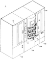
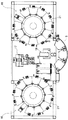
図1は、本発明を適用した錠剤充填装置1の外観を示す。錠剤充填装置1の正面中央に設けた中央扉2には、錠剤が充填されキャップ3で閉鎖されたバイアル瓶4が内側から載置される9個の取出棚5が設けられている。取出棚5は、バイアル瓶4を取り出し易いように前方に突出し、湾曲している。取出棚5の上方には、錠剤充填装置1を操作し必要な情報を表示する操作表示画面6が設けられている。取出棚5の左方には大小のキャップ3a,3bを投入するためのキャップ投入口7a,7bが形成されている。中央扉2の両側には錠剤カセット21の着脱時に開閉する左右扉8a,8bが設けられている。左扉8aの下方には内部装置の点検用の扉9a、中央扉2の下方にも内部装置の点検用の引出し9b、右扉8bの下方には大小のバイアル瓶4a,4bを投入するための2つの扉10a,10bが設けられている。
FIG. 1 shows the external appearance of a
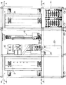
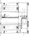
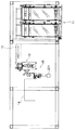
図2は、錠剤充填装置の扉等を取り外した正面図、図3は外装板を取り外した背面図、図4は図2のIV-IV線断面図、図5は図2のV-V線断面図である。これらの図を参照すると、錠剤充填装置1は、2つのバイアル瓶供給ユニット11、バイアル瓶搬送ベルト12、バイアル瓶搬送アームユニット13、ラベリングユニット14、バイアル瓶リフトユニット15、2つの錠剤供給ユニット16、第1バイアル瓶受渡しアームユニット17、第2バイアル瓶受渡しアームユニット18、キャップ供給ユニット19、キャッピングユニット20とからなっている。
2 is a front view of the tablet filling device with the doors removed, FIG. 3 is a rear view of the exterior plate removed, FIG. 4 is a sectional view taken along line IV-IV in FIG. 2, and FIG. 5 is a sectional view taken along line VV in FIG. It is. Referring to these drawings, the
バイアル瓶供給ユニット11は、正面から見て右下部に2つ設けられ、それぞれ大小2つのバイアル瓶4を保管し、処方に応じた錠剤を収容するのに必要なバイアル瓶4を取り出して供給する。
Two
バイアル瓶搬送ベルト12は、前記バイアル瓶供給ユニット11の背面に設けられ、中央に向かって水平に延び、前記バイアル瓶供給ユニット11から供給されたバイアル瓶4をバイアル瓶搬送アームユニット13に搬送する。
The
バイアル瓶搬送アームユニット13は、前記バイアル搬送ベルト12の終端に位置し、バイアル瓶搬送ベルト12から搬送されてくるバイアル瓶4を上方に開口するように方向変換し、ラベリングユニット14及びバイアル瓶リフトユニット15に搬送する。
The vial
ラベリングユニット14は、正面から見て左下部に位置し、バイアル瓶搬送アームユニット13から搬送されてくるバイアル瓶4にラベルを貼り付ける。
The
バイアル瓶リフトユニット15は、前記ラベリングユニット14と前記バイアル瓶搬送アームユニット13の間に位置し、前記ラベリングユニット14でラベルが貼り付けられたバイアル瓶4を上昇させて、第1バイアル瓶受渡しアームユニット17に引き渡す。
The
錠剤供給ユニット16は、正面から見て左右に位置し、回転可能なドラムの周囲に取り付けられた多数の錠剤フィーダを有し、錠剤フィーダから処方に応じた錠剤を排出して前記第1バイアル瓶受渡しアームユニットに保持されたバイアル瓶4に供給する。
The
第1バイアル瓶受渡しアームユニット17は、前記2つの錠剤供給ユニット16の間で、かつ、背面側に位置し、前記バイアル瓶リフトユニット15からバイアル瓶4を受け取り、前記錠剤供給ユニット16の任意の錠剤フィーダまで移動し、処方に応じた錠剤が充填されると、バイアル瓶4を第2バイアル瓶受渡しアームユニット18に引き渡す。
The first vial
第2バイアル瓶受渡しアームユニット18は、前記2つの錠剤供給ユニット16の間で、かつ、正面側に位置し、第1バイアル瓶受渡しアームユニット17から受け取ったバイアル瓶4をキャッピングユニット19に引き渡し、キャッピングされたバイアル瓶4を取出棚5に載置する。
The second vial
キャップ供給ユニット19は、前記第2バイアル瓶受渡しアームユニット18の正面からみて左側に位置し、バイアル瓶4を閉じるのに使用する大小2種類のキャップ3を収容し、いずれかのキャップ3を一つずつ供給する。
The
キャッピングユニット20は、前記キャップ供給ユニット19の下方に位置し、第2バイアル瓶受渡しアームユニット18から受け取ったバイアル瓶4に、キャップ供給ユニット19から供給されるキャップ3を取り付ける。
The capping
以下、本発明のキャップ供給装置であるキャップ供給ユニット19と、キャッピングユニット20について詳細に説明する。
<キャップ供給ユニット>
Hereinafter, the
<Cap supply unit>
図6は、キャップ供給ユニット19の正面外観図を示す。キャップ供給ユニット19は、大キャップ供給ユニット19aと小キャップ供給ユニット19bとが左右に隣接して配置されている。大キャップ供給ユニット19aの図において左側には、大キャップ導入ダクト101が取り付けられている。大キャップ導入ダクト101は、大キャップ供給ユニット19aの左側壁に形成された導入口101aから正面側に延設され、その正面の開口部101bは、前記扉28と対向している。小キャップ供給ユニット19bの正面には、小キャップ導入ダクト102が取り付けられている。小キャップ導入ダクト102は、小キャップ供給ユニット19bのカバー103と一体に形成され、このカバー103に形成された導入口102aから左側に延設され、さらに大キャップ供給ユニット19aの正面を通り越して大キャップ供給ユニット19aの左側から正面側に延設され、その正面の開口部102bは、前記扉28と対向している。図7は小キャップ導入ダクト102を取り外した状態を示す。大キャップ供給ユニット19aと小キャップ供給ユニット19bは、前記キャップ導入ダクト101,102を除き、同一の構成を有しているので、以下両者を区別することなく、説明する。
FIG. 6 is a front external view of the
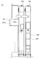
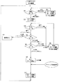
図9は、キャップ供給ユニット19の側面図を示す。キャップ供給ユニット19は、キャップの収納部104と、排出ユニット105と、撹拌ユニット106と、キャップ選択ユニット122とからなっている。
FIG. 9 shows a side view of the
収納部104は、前記キャップ導入ダクト101,102を通して投入された多数のキャップ3をランダムに収納する矩形箱形の容器である。
The
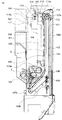
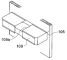
排出ユニット105は、収納部104の背面側の壁から底壁にかけて、2つのローラ107a,107b間に掛け渡された無端ベルト108を有し、前記無端ベルト108に一定間隔で支持部材109を設けたものである。無端ベルト108は、垂直部108aと、垂直部108aの下端から下方に斜めに延びる傾斜部108bとからなる。裏側の無端ベルト108の垂直部108aと傾斜部108bの間には内側からテンションローラ110が当接している。上側のローラ108aをモータ111によりギア111a,112を介して駆動することにより、表側の無端ベルト108は下端から斜め上方に上昇し、さらに垂直方向に上昇し、上端で折り返すように移動する。支持部材109は、図9に示すように、キャップ3の厚さよりやや大きい寸法で無端ベルト108から突出し、中央にはキャップ3が安定して支持されるように切欠き109aが形成されている。支持部材109は、図10の上部に示すように、キャップ3の開口部が無端ベルト108と反対側に向いているときは、キャップ3を安定して支持することができるが、図10の下部に示すように、キャップ3の開口部が無端ベルト108と対向しているときは支持部材109から脱落する。これは、縦向きにしたキャップ3の重心がキャップ3の肉厚の中心ではなく、開口部と反対側すなわち、閉鎖側にあるからである。
The
排出ユニット105の無端ベルト108の上端近傍には、支持部材109に支持されたキャップ3が折り返されるときに作動する検知レバー113と、前記検知レバー113の作動に応じてオンオフするセンサ114とが設けられている。
In the vicinity of the upper end of the
排出ユニット105の背後には、無端ベルト108の垂直部108aに並行に排出路115が形成されている。この排出路115は、排出ユニット105により搬送されて上端の折り返し部に到達したキャップ3を受け入れて下方に導くようになっている。排出路115の上端には、キャップ3を排出路115に案内するガイド板116が設けられている。
A
撹拌ユニット106は、複数のガイド117により、収納部104の内側壁に沿って垂直方向に往復移動可能に設けた撹拌板118を有している。撹拌板118の下部には、収納部104に収納されたキャップ3が係止する水平方向に延びる複数の係止孔118aが垂直方向に一定間隔で形成されている。この撹拌板118の係止孔118aは、孔に限らず、突起でも可能である。収納部104の容量を減少しない点では、係止孔118aのほうが好ましい。撹拌板118の上部には側縁に切欠き118bが形成され、この切欠き118bの上側の縁に、前記排出ユニット105のモータ111の駆動ギヤ111aと噛合するギヤ119と一体に設けたカム120の先端のローラ121が当接することで、前記排出ユニット105の無端ベルト108と連動して、垂直方向に周期的に往復移動するようになっている。
The stirring
キャップ選択ユニット122は、シュート123、大キャップ用ロータ124a、小キャップ用ロータ124bを有している。
The
シュート123は、傾斜して設けられ、上端は、前記大キャップ供給ユニット19aの排出路115a、前記小キャップ供給ユニット19bの排出路115bと接続され、両者から大キャップ3aと小キャップ3bを受け入れるようになっている。シュート123の下端は、大キャップ3aと小キャップ3bのいずれか1つが通過する幅に絞られている。シュート123の両端の側壁間には、シュート123の傾斜面と対向するように基板125が取り付けられている。
The
大キャップ用ロータ124aと小キャップ用ロータ124bは、シュート123と基板の間に、それぞれ左側、右側に配置され、基板125に取り付けられたモータ126により回転駆動されるようになっている。大キャップ用ロータ124aは、欠円形の板状で、裏面に溝127を形成したものである。溝127は、図において上部に大キャップ3aが通過可能な幅広部127aと、この幅広部127aの下方に大キャップ3aは通過しないが小キャップ3bが通過可能な幅狭部127bと、前記幅広部127aと幅狭部127bの間に第1傾斜部127c、前記幅狭部127bの下方に第2傾斜部127dとからなっている。幅広部127aの入口の縁にはキャップ3aを受け入れ易くするためにテーパ面128が形成されている。前記溝127の幅広部127a、第1傾斜部127c及びシュート123により、本来受け入れられるべき大キャップ3aを受け入れ可能な大キャップ受入部129(以下、OK大キャップ受入部という)を構成し、幅狭部127b、第2傾斜部127d及びシュート123により、本来受け入れられるべきでない小キャップ3bを受け入れ可能な小キャップ受入部130(NG小キャップ受入部という)を構成している。大キャップ用ロータ124aには、OK大キャップ受入部129に貫通孔131が形成され、NG小キャップ受入部130に切欠き132が形成されている。さらに大キャップ用ロータ124aには偏心位置に磁石133が埋設されている。
The
小キャップ用ロータ124bは、円形の板状で、大キャップ用ロータ124aと同様に、裏面に溝134を形成したものである。溝134は、図において上部に大キャップ3aが通過可能な幅広部134aが形成され、この幅広部134aの下方に大キャップ3aは通過しないが小キャップ3bが通過可能な幅狭部134bが形成されている。前記幅広部134aと幅狭部134bの間は傾斜部134cが形成されている。また、幅広部134aの入口の縁にはキャップ3bを受け入れ易くするためにテーパ面135が形成されている。前記溝134の幅広部134a、第1傾斜部127c及びシュート123により、本来受け入れられるべきでない大キャップ3aを受け入れ可能な大キャップ受入部136(以下、NG大キャップ受入部という)を構成し、幅狭部134b、シュート123及びシュート123に突設されたストッパ138により、本来受け入れられるべき小キャップ3bを受け入れ可能な小キャップ受入部137(OK小キャップ受入部という)を構成している。小キャップ用ロータ124bには、NG大キャップ受入部136に貫通孔139が形成され、OK小キャップ受入部137に切欠き140が形成されている。さらに小キャップ用ロータ124bには偏心位置に磁石141が埋設されている。
The
前記基板125の左側部には、大キャップ用ロータ124aのOK大キャップ受入部129が上向き、すなわち大キャップ3aの排出路115aに向いているときに、大キャップ用ロータ124aの磁石133を検出する原点センサ142、OK大キャップ受入部129の貫通孔131と対向するOKセンサ143、NG小キャップ受入部130の切欠き132と対向するNGセンサ144が設けられている。同様に、前記基板125の右側部には、小キャップ用ロータ124bのNG大キャップ受入部136が上向き、すなわち小キャップ3bの排出路115bに向いているときに、小キャップ用ロータ124bの磁石141を検出する原点センサ145、NG大キャップ受入部136の貫通孔139と対向するNGセンサ146、OK小キャップ受入部137の切欠き140と対向するOKセンサ147が設けられている。
On the left side of the
前記構成のキャップ供給ユニット19の動作を図14のフローチャートに従って説明する。以下の説明は大キャップ3aについてであるが、小キャップ3bも同様である。
The operation of the
まず、ステップS1でキャップ選択ユニット122の原点センサ142がONかOFFかを判断し、OFFであればステップS2でロータ駆動モータ126を運転し、原点センサ142がONになるとステップS3でロータ駆動モータ126を停止する。ステップS4でキャップ供給ユニット19の排出センサ114がキャップ3の通過により遮光されると、排出路115aにキャップ3aが有ることが分かる。そこで、ステップS5で、NGセンサ144が入光を検出するか否かにより、NG小キャップ受入部130にキャップ3aが有るか無いかを判断する。ステップS4でキャップ排出ユニット19の排出センサ114が通光したままであれば、排出路115aにキャップ3aが無いので、ステップS9で排出モータ111を運転し、ステップS4に戻ってキャップ3aが排出されるまで待機する。
First, in step S1, it is determined whether the
ステップS5で、NG小キャップ受入部130に小キャップ3bが無いと判断すれば、大キャップ3aを受け入れて、大キャップ用ロータ124aを回動させることにより、その大キャップ3aのみを供給することができる。そこで、ステップS6でOKセンサ143が入光を検出し、OK大キャップ受入部129に大キャップ3aが有ると判断すると、ステップS7で排出モータ111を停止し、キャップ供給指令を待つ。また、OKセンサ143が入光を検出せず、OK大キャップ受入部129に大キャップ3aが無いと判断すると、ステップS9で排出モータ11を運転し、ステップS4に戻り、OK大キャップ受入部129に大キャップ3aが受け入れられるまで前記ステップを繰り返す。
If it is determined in step S5 that there is no
ステップS5で、NG小キャップ受入部130に小キャップ3bが有ると判断すれば、大キャップ3aを受け入れて、大キャップ用ロータ124aを回動させると、大キャップ3aと小キャップ3bが排出されてしまう。従って、ステップS8で異常を表示する。
If it is determined in step S5 that the small
ステップS7の後、キャップ供給指令が出ると、ステップS11でロータ駆動モータ126を運転し、大キャップ用ロータ124aを図において時計回りに約180度回動させる。これにより、大キャップ3aは、2点鎖線で示すように、キャッピングユニット20に供給される。
When a cap supply command is issued after step S7, the
<キャッピングユニット>
図15は、キャッピングユニット20の方面図(a)及び側面図(b)を示す。キャッピングユニット20は、バイアル瓶昇降装置201と、キャッピング本体202とからなっている。
<Capping unit>
FIG. 15 shows a direction view (a) and a side view (b) of the
バイアル瓶昇降装置201は、バイアル瓶4が載置される昇降台203を備えている。昇降台203は、前記第2バイアル瓶受渡しアームユニット18との間でバイアル瓶4の受け渡しを行う下降位置と、キャッピング本体202との間でバイアル瓶4の受け渡しを行う上昇位置との間で昇降可能に設けられている。昇降台203には、滑り止め用のゴム製のマット204が設けられている。
The vial raising / lowering
キャッピング本体202は、前記キャップ供給ユニット19の下方に設けられ、装置本体1aに固定されたベース構造205に、1対のバイアル瓶保持アーム206、1対のキャップ支持レバー207、及びキャッピングロータ208を取り付けたものである。
The
バイアル瓶保持アーム206は、ベース構造205に平行に配設されたガイド軸209と駆動軸210に支持され、モータ211により駆動軸210を回転させることでキャッピング本体202の正面からみて左右水平方向に互いに接近し離隔する1対のアーム本体212を備えている。1対のアーム本体212の下部には、バイアル瓶4を保持する保持部213が先端に揺動可能に取り付けられた軸214が挿通されている。保持部213とアーム本体212の間にはコイルばね215が装着され、保持部213でバイアル瓶4を保持したときの衝撃を緩和するようになっている。1対のアーム本体212の上部には、キャップ3を保持しガイドするガイド部216が取り付けられた1対の軸部217が挿通されている。ガイド部216とアーム本体212の間にもコイルばね218が装着され、ガイド部216でキャップ3を保持したときの衝撃を緩和するようになっている。
The
キャップ支持レバー207は、ベース構造205から水平に延設された矩形の枠体219に、キャッピング本体202の正面からみて前後の位置に取り付けられている。キャップ支持レバー207は、キャッピング本体202の側方から見て略L字形で、軸220を中心に回動可能に設けられ、先端にキャップ3を支持する支持部221を有している。キャップ支持レバー207は、図の実線で示すように枠体219の一部に当接して支持部221が水平になりキャップ3を支持可能な支持位置と、図の2点鎖線で示すように支持部221が傾斜してキャップ3を通過させることが可能な退避位置との間で回動可能で、かつ図示しないばねにより支持位置に向かって付勢されている。キャップ支持レバー207の支持位置は、前記キャップ選択ユニット122のシュート123の下端よりも下方で、前記バイアル瓶保持アーム206のガイド部216の下面とほぼ同じレベルに位置し、シュート123から供給されるキャップ3を支持できるようになっている。
The
キャッピングロータ208は、ベース構造205から上方に延びる1対のロッド222に挿通された基台223にモータ224により回転駆動可能に設けられている。キャッピングロータ208は、モータ224の駆動軸225に設けたディスク226に摺動可能に挿通された1対の軸227の下端に取り付けられている。ディスク226とロータ208の間の軸にはばね228が装着され、ロータ208でキャップ3を押圧するときの衝撃を緩和するようになっている。また、基台223にはラック229が取り付けられ、このラック229がベース構造205に設けたモータ230のピニオン231と噛合することで、基台223は昇降可能になっている。
The capping
前記構成のキャッピング装置20の動作を図16に従って説明すると、まず、図16(a)に示すように、前記キャップ選択ユニット122のシュート123からキャップ3が供給され、キャップ支持レバー207上に支持される。錠剤が充填されたバイアル瓶4は、前記第2バイアル瓶受渡しアームユニット18によりバイアル瓶昇降装置201の昇降台203に載置されて上昇位置に移動する。次に、図16(b)に示すように、バイアル瓶保持アーム206が駆動して、保持部213によりバイアル瓶4を保持すると同時に、ガイド部216によりキャップ3を保持する。そして、図16(c)に示すように、キャッピングロータ208が下降してキャップ3をバイアル瓶4に向かって押し付ける。このとき、キャップ支持レバー207は退避位置に付勢力に抗して退避するので、キャップ3は保持部213にガイドされながらキャップ支持レバー207を通過してバイアル瓶4に押し付けられる。ここで、キャッピングロータ208が回転し、キャップ3がバイアル瓶4に締め付けられる。キャッピングが終了すると、ロータ208は上昇して元の位置に復帰する。なお、退避位置にあるキャップ支持レバー207はキャッピングロータ208に接触していて,キャッピングロータ208が上昇すると、支持位置に復帰する。最後に、バイアル瓶保持アーム206が駆動して、退避位置に復帰する。これにより、キャッピングされたバイアル瓶4は、バイアル瓶昇降装置201の下降によって下降位置に復帰し、第2バイアル瓶受渡しアームユニット18に引き渡される。
The operation of the
3 キャップ
19 キャップ供給ユニット
20 キャッピングユニット
104 キャップ収納部
105 排出ユニット
106 撹拌ユニット
108 無端ベルト
108a 垂直部
108b 傾斜部
109 支持部材
115 排出路
116 ガイド板
118 撹拌板
118a 係止孔
122 キャップ選択ユニット
124 ロータ
129 大キャップ受入部
130 小キャップ受入部
136 大キャップ受入部
137 小キャップ受入部
3
Claims (9)
前記多数のキャップを収納する収納部と、
前記収納部内に、無端部材を垂直方向に周回可能に配置し、前記無端部材に支持部材を一定間隔で設け、前記支持部材に前記キャップの開口部を前記無端部材と反対側に向けて縦向きに支持しながら上方に持ち上げて前記収納部から排出する排出ユニットと、
を備えたことを特徴とするキャップ供給装置。 In a cap supply device for storing a large number of caps for closing a vial filled with tablets, taking out the caps one by one and supplying them to a capping unit,
A storage section for storing the multiple caps;
An endless member is arranged in the storage portion so as to be able to circulate in a vertical direction, a support member is provided at a predetermined interval on the endless member, and the opening of the cap is vertically directed toward the opposite side of the endless member in the support member A discharge unit that lifts up and discharges from the storage unit while supporting
A cap supply device comprising:
キャップを受け入れ可能なキャップ受入部を有し、前記キャップ受入部が前記各キャップ供給装置から排出されるキャップの排出方向に対向する受入位置と、前記キャップ受入部がキャップの供給方向に向けられる供給位置との間で回転可能で、前記複数のキャップ供給装置毎に設けられた複数の回転部材を有し、
前記複数の回転部材を選択的に回転させることにより、各キャップ供給装置から排出されるキャップのいずれかを選択して供給することを特徴とする請求項8に記載のキャップ供給装置。
The cap selection unit is
A cap receiving portion capable of receiving a cap, wherein the cap receiving portion is opposed to the discharging direction of the cap discharged from each cap supply device, and the cap receiving portion is directed to the cap supplying direction. A plurality of rotating members provided for each of the plurality of cap supply devices;
9. The cap supply device according to claim 8, wherein one of the caps discharged from each cap supply device is selectively supplied by selectively rotating the plurality of rotating members.
Priority Applications (5)
| Application Number | Priority Date | Filing Date | Title |
|---|---|---|---|
| JP2006132493A JP2007302300A (en) | 2006-05-11 | 2006-05-11 | Cap feeding device |
| PCT/JP2007/059081 WO2007132665A1 (en) | 2006-05-11 | 2007-04-26 | Cap supply device |
| US12/300,457 US8196371B2 (en) | 2006-05-11 | 2007-04-26 | Cap supply device |
| CN2007800170814A CN101443258B (en) | 2006-05-11 | 2007-04-26 | Cap feeding device |
| KR1020087027193A KR20090026127A (en) | 2006-05-11 | 2007-04-26 | Cap supply device |
Applications Claiming Priority (1)
| Application Number | Priority Date | Filing Date | Title |
|---|---|---|---|
| JP2006132493A JP2007302300A (en) | 2006-05-11 | 2006-05-11 | Cap feeding device |
Publications (2)
| Publication Number | Publication Date |
|---|---|
| JP2007302300A true JP2007302300A (en) | 2007-11-22 |
| JP2007302300A5 JP2007302300A5 (en) | 2009-06-18 |
Family
ID=38693764
Family Applications (1)
| Application Number | Title | Priority Date | Filing Date |
|---|---|---|---|
| JP2006132493A Pending JP2007302300A (en) | 2006-05-11 | 2006-05-11 | Cap feeding device |
Country Status (5)
| Country | Link |
|---|---|
| US (1) | US8196371B2 (en) |
| JP (1) | JP2007302300A (en) |
| KR (1) | KR20090026127A (en) |
| CN (1) | CN101443258B (en) |
| WO (1) | WO2007132665A1 (en) |
Cited By (3)
| Publication number | Priority date | Publication date | Assignee | Title |
|---|---|---|---|---|
| JP2011504856A (en) * | 2007-11-29 | 2011-02-17 | カーハーエス・ゲゼルシャフト・ミト・ベシュレンクテル・ハフツング | Container sealing device |
| CN106005994A (en) * | 2016-07-14 | 2016-10-12 | 浙江卓怡纺织有限公司 | Plastic bottle lid loading device |
| CN106044670A (en) * | 2016-06-27 | 2016-10-26 | 武汉中原瑞德生物制品有限责任公司 | Packaging cover adding device used for filling production and filling machine with packaging cover adding device |
Families Citing this family (10)
| Publication number | Priority date | Publication date | Assignee | Title |
|---|---|---|---|---|
| JP2007302300A (en) * | 2006-05-11 | 2007-11-22 | Yuyama Manufacturing Co Ltd | Cap feeding device |
| CN102069630B (en) * | 2010-11-09 | 2012-05-09 | 广州丽盈塑料有限公司 | Feeding system of bottle cap automatic hot stamping machine |
| US9394107B1 (en) * | 2011-03-04 | 2016-07-19 | Express Scripts, Inc. | Systems and methods for manual handling |
| CN104220350B (en) * | 2012-01-31 | 2016-12-14 | Abb研究有限公司 | Method and system for feed element |
| US10800565B1 (en) | 2014-05-07 | 2020-10-13 | Express Scripts Strategic Development, Inc. | Systems and methods for capping |
| CN103979473B (en) * | 2014-05-30 | 2016-03-23 | 湖南千山制药机械股份有限公司 | The device of conveying closure elements |
| WO2016130962A1 (en) | 2015-02-13 | 2016-08-18 | Abbott Laboratories | Automated storage modules for diagnostic analyzer liquids and related systems and methods |
| US9376301B1 (en) | 2015-07-16 | 2016-06-28 | Jalbert Automatisation Inc. | Adjustable cap sorter |
| CN105944780B (en) * | 2016-04-25 | 2017-12-22 | 烟台海深威医学技术有限公司 | Test tube pressing device and intelligent test tube capped system |
| CN112938859B (en) * | 2021-03-03 | 2023-01-17 | 临沂金悦环保科技有限公司 | Automatic capping device |
Citations (10)
| Publication number | Priority date | Publication date | Assignee | Title |
|---|---|---|---|---|
| JPS494366A (en) * | 1972-05-02 | 1974-01-16 | ||
| JPS57194981A (en) * | 1981-05-21 | 1982-11-30 | Tatsuzou Enzaki | Method of arranging and covering bottle cover and device for arranging and covering bottle cover |
| JPS63116410A (en) * | 1986-11-05 | 1988-05-20 | Fujikura Ltd | Printed coil and regulating method for its inductance |
| JPH04101927A (en) * | 1990-08-15 | 1992-04-03 | Shibuya Kogyo Co Ltd | Remaining article discharging device of article feeder |
| JPH05270584A (en) * | 1992-03-25 | 1993-10-19 | Shibuya Kogyo Co Ltd | Cap transfer device |
| US5394972A (en) * | 1994-02-22 | 1995-03-07 | Aidlin; Stephen H. | Variable angle conveyor assembly |
| JP2005211519A (en) * | 2004-01-30 | 2005-08-11 | Yuyama Manufacturing Co Ltd | Medicine storing and dispensing apparatus |
| JP2006082820A (en) * | 2004-09-14 | 2006-03-30 | Shibuya Kogyo Co Ltd | Rotary capping device |
| JP2006240738A (en) * | 2005-02-07 | 2006-09-14 | Yuyama Manufacturing Co Ltd | Vial capping device and vial capping method |
| WO2007132665A1 (en) * | 2006-05-11 | 2007-11-22 | Yuyama Mfg. Co., Ltd. | Cap supply device |
Family Cites Families (34)
| Publication number | Priority date | Publication date | Assignee | Title |
|---|---|---|---|---|
| US2732114A (en) * | 1956-01-24 | Machine for | ||
| US1651902A (en) * | 1921-03-07 | 1927-12-06 | Standard Automatic Machine Com | Machine for applying closures to containers |
| US2154266A (en) * | 1937-05-24 | 1939-04-11 | William B Willcutt | Method of and apparatus for vacuum sealing containers |
| US2352761A (en) * | 1939-04-08 | 1944-07-04 | Anchor Hocking Glass Corp | Apparatus for sealing containers |
| US3382646A (en) * | 1966-03-10 | 1968-05-14 | Johnson & Son Inc S C | Capper |
| FR1603519A (en) * | 1968-11-08 | 1971-05-03 | ||
| CH514467A (en) * | 1968-11-29 | 1971-10-31 | Benz & Hilgers Gmbh | Device for inserting cover sheets or covering lids for cup-shaped containers |
| US3623594A (en) * | 1969-10-23 | 1971-11-30 | West Co | Cap-feeding apparatus |
| US3780493A (en) * | 1971-11-15 | 1973-12-25 | Diamond Int Corp | Package capping apparatus |
| JPS494366U (en) * | 1972-04-14 | 1974-01-15 | ||
| US3970218A (en) * | 1975-02-20 | 1976-07-20 | Lee Wing J | Cap selecting and feeding mechanism |
| US4065909A (en) * | 1976-04-26 | 1978-01-03 | Owens-Illinois, Inc. | Method and apparatus for applying a lid and tamper-indicating sheet to a container |
| US4222214A (en) * | 1978-06-13 | 1980-09-16 | Eastman Kodak Company | Chucking apparatus |
| US4735343A (en) * | 1984-03-19 | 1988-04-05 | Michael Herzog | Feeder for bottle capper |
| US4696144A (en) * | 1986-10-29 | 1987-09-29 | New England Machinery, Inc. | Container capper and torque tester |
| JPH0439206Y2 (en) * | 1987-01-21 | 1992-09-14 | ||
| US4995781A (en) * | 1989-11-03 | 1991-02-26 | Herzog Kenneth J | Movable auxiliary hopper |
| JP2959577B2 (en) | 1990-05-31 | 1999-10-06 | エヌティエヌ株式会社 | Vibration feeder |
| US5208762A (en) | 1990-12-06 | 1993-05-04 | Baxter International Inc. | Automated prescription vial filling system |
| US5115617A (en) * | 1990-12-12 | 1992-05-26 | H. G. Kalish Inc. | Capping machine |
| US5159797A (en) * | 1991-02-15 | 1992-11-03 | Herzog Kenneth J | Ball cap orienter |
| DE9104140U1 (en) * | 1991-04-05 | 1992-03-05 | Krones Ag Hermann Kronseder Maschinenfabrik, 8402 Neutraubling, De | |
| JP2652501B2 (en) * | 1993-04-08 | 1997-09-10 | 花王株式会社 | Filling method and device |
| US5333718A (en) * | 1993-08-24 | 1994-08-02 | Pannell Lorris O | Apparatus for handling plastic eating utensils |
| US5502944A (en) | 1993-12-03 | 1996-04-02 | Owen Healthcare, Inc. | Medication dispenser system |
| US5586637A (en) * | 1994-02-22 | 1996-12-24 | Aidlin; Samuel S. | Variable angle conveyor assembly with stepped cleat |
| JPH07251915A (en) | 1994-03-14 | 1995-10-03 | Lintec Corp | Cap feeding device and feeding method thereof |
| US5531057A (en) * | 1995-09-08 | 1996-07-02 | Crown Cork And Seal Company, Inc. | Bottle cap delivery system |
| JP4101927B2 (en) | 1997-05-28 | 2008-06-18 | Agcセイミケミカル株式会社 | Non-aqueous electrolyte secondary battery |
| DE19727942C2 (en) * | 1997-07-01 | 1999-04-15 | Gea Finnah Gmbh | Machine and method for closing bottles with caps |
| US6430896B1 (en) * | 2000-03-23 | 2002-08-13 | Kalish, Inc. | Capping machine |
| JP4716628B2 (en) | 2000-10-02 | 2011-07-06 | 靜甲株式会社 | Cap feeder |
| FR2876991B1 (en) * | 2004-10-25 | 2007-02-16 | Sidel Sas | IMPROVEMENT TO THE CONVEYOR DEVICE USED FOR THE ROUTING OF ORIENTED OBJECTS OF THE GENUS CAPSULES, COVERS, CAPS, ETC, BETWEEN THE MACHINE FOR THE PRIMER OF THESE OBJECTS AND THEIR DESTINATION |
| WO2006082969A1 (en) | 2005-02-07 | 2006-08-10 | Yuyama Mfg. Co., Ltd. | Vial capping device and vial capping method |
-
2006
- 2006-05-11 JP JP2006132493A patent/JP2007302300A/en active Pending
-
2007
- 2007-04-26 CN CN2007800170814A patent/CN101443258B/en not_active Expired - Fee Related
- 2007-04-26 US US12/300,457 patent/US8196371B2/en not_active Expired - Fee Related
- 2007-04-26 WO PCT/JP2007/059081 patent/WO2007132665A1/en active Application Filing
- 2007-04-26 KR KR1020087027193A patent/KR20090026127A/en not_active Application Discontinuation
Patent Citations (10)
| Publication number | Priority date | Publication date | Assignee | Title |
|---|---|---|---|---|
| JPS494366A (en) * | 1972-05-02 | 1974-01-16 | ||
| JPS57194981A (en) * | 1981-05-21 | 1982-11-30 | Tatsuzou Enzaki | Method of arranging and covering bottle cover and device for arranging and covering bottle cover |
| JPS63116410A (en) * | 1986-11-05 | 1988-05-20 | Fujikura Ltd | Printed coil and regulating method for its inductance |
| JPH04101927A (en) * | 1990-08-15 | 1992-04-03 | Shibuya Kogyo Co Ltd | Remaining article discharging device of article feeder |
| JPH05270584A (en) * | 1992-03-25 | 1993-10-19 | Shibuya Kogyo Co Ltd | Cap transfer device |
| US5394972A (en) * | 1994-02-22 | 1995-03-07 | Aidlin; Stephen H. | Variable angle conveyor assembly |
| JP2005211519A (en) * | 2004-01-30 | 2005-08-11 | Yuyama Manufacturing Co Ltd | Medicine storing and dispensing apparatus |
| JP2006082820A (en) * | 2004-09-14 | 2006-03-30 | Shibuya Kogyo Co Ltd | Rotary capping device |
| JP2006240738A (en) * | 2005-02-07 | 2006-09-14 | Yuyama Manufacturing Co Ltd | Vial capping device and vial capping method |
| WO2007132665A1 (en) * | 2006-05-11 | 2007-11-22 | Yuyama Mfg. Co., Ltd. | Cap supply device |
Cited By (6)
| Publication number | Priority date | Publication date | Assignee | Title |
|---|---|---|---|---|
| JP2011504856A (en) * | 2007-11-29 | 2011-02-17 | カーハーエス・ゲゼルシャフト・ミト・ベシュレンクテル・ハフツング | Container sealing device |
| US8915047B2 (en) | 2007-11-29 | 2014-12-23 | Khs Gmbh | Beverage bottle closing machine being configured and disposed to close tops of filled beverage bottles with screw-type and other caps |
| US10000369B2 (en) | 2007-11-29 | 2018-06-19 | Khs Gmbh | Beverage bottle closing machine being configured and disposed to close tops of filled beverage bottles with screw-type and other caps |
| CN106044670A (en) * | 2016-06-27 | 2016-10-26 | 武汉中原瑞德生物制品有限责任公司 | Packaging cover adding device used for filling production and filling machine with packaging cover adding device |
| CN106044670B (en) * | 2016-06-27 | 2019-07-26 | 武汉中原瑞德生物制品有限责任公司 | For the cap adding set of filling production and with its bottle placer |
| CN106005994A (en) * | 2016-07-14 | 2016-10-12 | 浙江卓怡纺织有限公司 | Plastic bottle lid loading device |
Also Published As
| Publication number | Publication date |
|---|---|
| CN101443258A (en) | 2009-05-27 |
| US20090241470A1 (en) | 2009-10-01 |
| CN101443258B (en) | 2010-12-08 |
| KR20090026127A (en) | 2009-03-11 |
| US8196371B2 (en) | 2012-06-12 |
| WO2007132665A1 (en) | 2007-11-22 |
Similar Documents
| Publication | Publication Date | Title |
|---|---|---|
| JP2007302300A (en) | Cap feeding device | |
| JP2007302300A5 (en) | ||
| JP4940752B2 (en) | Vial supply device | |
| JP4992262B2 (en) | Drug dispensing device | |
| US7562791B2 (en) | Tablet filling device | |
| US8204621B2 (en) | Tablet discharging method | |
| JP4910481B2 (en) | Tablet filling equipment | |
| US7575129B2 (en) | Vial supply apparatus | |
| JP2006224980A (en) | Tablet filling device | |
| JP2009000291A (en) | Tablet filling apparatus | |
| KR100828586B1 (en) | medicine feed apparatus | |
| JP2008013216A (en) | Medicine storing and dispensing apparatus | |
| JP4802856B2 (en) | Tablet feeder | |
| JP4964199B2 (en) | Individual packaging medicine automatic supply equipment | |
| JP4782170B2 (en) | Tablet filling equipment | |
| US9767635B2 (en) | Medicament dispensing machine | |
| JP2005211538A5 (en) | ||
| CN111164657B (en) | Delivery device | |
| KR100631588B1 (en) | Ampoule feeder | |
| JP5153506B2 (en) | Individual packaging medicine automatic supply equipment | |
| JP4836879B2 (en) | Drug supply device | |
| JPH08133421A (en) | Injection drug take out device | |
| JP2011078600A (en) | Automatic medicine feeder |
Legal Events
| Date | Code | Title | Description |
|---|---|---|---|
| A521 | Written amendment |
Free format text: JAPANESE INTERMEDIATE CODE: A523 Effective date: 20090423 |
|
| A621 | Written request for application examination |
Free format text: JAPANESE INTERMEDIATE CODE: A621 Effective date: 20090423 |
|
| A131 | Notification of reasons for refusal |
Free format text: JAPANESE INTERMEDIATE CODE: A131 Effective date: 20110816 |
|
| A521 | Written amendment |
Free format text: JAPANESE INTERMEDIATE CODE: A523 Effective date: 20111005 |
|
| A02 | Decision of refusal |
Free format text: JAPANESE INTERMEDIATE CODE: A02 Effective date: 20111213 |