JP2007302154A - On-vehicle input device - Google Patents
On-vehicle input device Download PDFInfo
- Publication number
- JP2007302154A JP2007302154A JP2006134132A JP2006134132A JP2007302154A JP 2007302154 A JP2007302154 A JP 2007302154A JP 2006134132 A JP2006134132 A JP 2006134132A JP 2006134132 A JP2006134132 A JP 2006134132A JP 2007302154 A JP2007302154 A JP 2007302154A
- Authority
- JP
- Japan
- Prior art keywords
- driver
- seat
- passenger
- input operation
- operation unit
- Prior art date
- Legal status (The legal status is an assumption and is not a legal conclusion. Google has not performed a legal analysis and makes no representation as to the accuracy of the status listed.)
- Withdrawn
Links
- 230000003287 optical effect Effects 0.000 claims description 22
- 230000005616 pyroelectricity Effects 0.000 abstract 4
- 238000000034 method Methods 0.000 description 7
- 230000008569 process Effects 0.000 description 5
- 238000001514 detection method Methods 0.000 description 4
- 238000010586 diagram Methods 0.000 description 3
- 238000004519 manufacturing process Methods 0.000 description 3
- 230000004044 response Effects 0.000 description 3
- 230000009471 action Effects 0.000 description 2
- 238000007796 conventional method Methods 0.000 description 2
- 230000009467 reduction Effects 0.000 description 2
- 230000000694 effects Effects 0.000 description 1
- 239000004973 liquid crystal related substance Substances 0.000 description 1
Images


Classifications
-
- B—PERFORMING OPERATIONS; TRANSPORTING
- B60—VEHICLES IN GENERAL
- B60R—VEHICLES, VEHICLE FITTINGS, OR VEHICLE PARTS, NOT OTHERWISE PROVIDED FOR
- B60R21/00—Arrangements or fittings on vehicles for protecting or preventing injuries to occupants or pedestrians in case of accidents or other traffic risks
- B60R21/01—Electrical circuits for triggering passive safety arrangements, e.g. airbags, safety belt tighteners, in case of vehicle accidents or impending vehicle accidents
- B60R21/015—Electrical circuits for triggering passive safety arrangements, e.g. airbags, safety belt tighteners, in case of vehicle accidents or impending vehicle accidents including means for detecting the presence or position of passengers, passenger seats or child seats, and the related safety parameters therefor, e.g. speed or timing of airbag inflation in relation to occupant position or seat belt use
- B60R21/01512—Passenger detection systems
- B60R21/0153—Passenger detection systems using field detection presence sensors
- B60R21/01534—Passenger detection systems using field detection presence sensors using electromagneticwaves, e.g. infrared
-
- B60K35/10—
-
- B60K35/654—
-
- B60K35/656—
-
- B60K2360/143—
-
- B—PERFORMING OPERATIONS; TRANSPORTING
- B60—VEHICLES IN GENERAL
- B60R—VEHICLES, VEHICLE FITTINGS, OR VEHICLE PARTS, NOT OTHERWISE PROVIDED FOR
- B60R11/00—Arrangements for holding or mounting articles, not otherwise provided for
- B60R11/02—Arrangements for holding or mounting articles, not otherwise provided for for radio sets, television sets, telephones, or the like; Arrangement of controls thereof
- B60R11/0264—Arrangements for holding or mounting articles, not otherwise provided for for radio sets, television sets, telephones, or the like; Arrangement of controls thereof for control means
-
- B—PERFORMING OPERATIONS; TRANSPORTING
- B60—VEHICLES IN GENERAL
- B60R—VEHICLES, VEHICLE FITTINGS, OR VEHICLE PARTS, NOT OTHERWISE PROVIDED FOR
- B60R11/00—Arrangements for holding or mounting articles, not otherwise provided for
- B60R2011/0001—Arrangements for holding or mounting articles, not otherwise provided for characterised by position
- B60R2011/0003—Arrangements for holding or mounting articles, not otherwise provided for characterised by position inside the vehicle
- B60R2011/0007—Mid-console
Abstract
Description
本発明は、運転席と助手席との間に設置された入力操作部が、運転席に座った運転者により操作されるのか、助手席に座った同乗者により操作されるのかを判定する車載用入力装置に関する。 The present invention relates to an on-vehicle vehicle that determines whether an input operation unit installed between a driver seat and a passenger seat is operated by a driver sitting in the driver seat or a passenger sitting in the passenger seat. It relates to an input device.
従来の車載用入力装置としては、特許文献1に開示された従来技術がある。この従来技術は、運転席と助手席との間に設置された入力操作部と、この入力操作部が運転席に座った運転者の手指で操作されるのか、助手席に座った同乗者の手指で操作されるのかを判定する判定手段とを備えている。
As a conventional in-vehicle input device, there is a conventional technique disclosed in
この従来技術では、判定手段が、入力操作部から運転者と同乗者とを含む所定範囲を撮影可能に設置された赤外線カメラと、この赤外線カメラからの画像データを処理して入力操作部に伸ばされた手が、運転者であるか同乗者であるかを判定する画像処理装置とから構成されている。
前述した従来技術は、赤外線カメラと画像処理装置とから構成された判定手段を備えている。赤外線カメラ等のディバイスは鮮明な画像を得るための複数枚のレンズやCCD等のイメージセンサを備えていて構成が複雑であり、画像処理装置には複雑なアルゴリズムの画像処理プログラムが必要になる。このため、前述した従来技術は製作コストが高いという問題がある。 The above-described prior art includes a determination unit that includes an infrared camera and an image processing apparatus. A device such as an infrared camera is provided with a plurality of lenses for obtaining a clear image and an image sensor such as a CCD and has a complicated structure, and the image processing apparatus requires an image processing program of a complicated algorithm. For this reason, the above-described conventional technique has a problem that the manufacturing cost is high.
本発明は、前述の実状を考慮してなされたもので、その目的は、運転席と助手席の間に設置されている入力操作部が、運転席に座った運転者により操作されるのか、助手席に座った同乗者により操作されるのかを、簡単な構成で判定することができる車載用入力装置を提供することにある。 The present invention has been made in consideration of the above-described actual situation, and the purpose thereof is whether the input operation unit installed between the driver's seat and the passenger seat is operated by the driver sitting in the driver's seat, An object of the present invention is to provide an in-vehicle input device that can determine with a simple configuration whether it is operated by a passenger sitting in a passenger seat.
〔1〕 本発明は、運転席と助手席との間に設置された入力操作部と、この入力操作部が運転席に座った運転者により操作されるのか、助手席に座った同乗者により操作されるのかを判定する判定手段とを備えた車載用入力装置であって、前記判定手段が、前記運転席と前記入力操作部との間における物体の存在を感知可能に設けられた運転席側光学式スイッチと、前記助手席と前記入力操作部との間における物体の存在を感知可能に設けられた助手席側光学式スイッチと、運転席側光学式スイッチが物体の存在を感知したことを基に前記運転者により前記入力操作部が操作されると判定し、前記助手席側光学式スイッチが物体の存在を感知したことを基に前記同乗者により前記入力操作部が操作されると判定する判定部とから構成されていることを特徴とする。 [1] The present invention provides an input operation unit installed between a driver seat and a passenger seat, and whether the input operation unit is operated by a driver sitting in the driver seat or by a passenger sitting in the passenger seat. A vehicle-mounted input device including a determination unit that determines whether or not the driver is operated, wherein the determination unit is provided so as to be able to detect the presence of an object between the driver seat and the input operation unit. The side optical switch, the passenger side optical switch provided so as to detect the presence of an object between the passenger seat and the input operation unit, and the driver side optical switch have detected the presence of the object. The driver determines that the input operation unit is operated, and the passenger operates the input operation unit based on the fact that the passenger-side optical switch senses the presence of an object. And a judgment unit It is characterized in.
このように構成された本発明では、判定手段が運転席側光学式スイッチと助手席側光学式スイッチを備えている。これらのスイッチは焦電センサや反射型光電スイッチ等の赤外線カメラよりも簡単なもので構成されている。また、本発明では、入力操作部が運転者により操作されるのか、助手席に座った同乗者により操作されるのかの判定が、運転席側光学式スイッチおよび助手席側光学式スイッチのどちらで物体の存在が感知されたか否かによって行われるので、その判定を行わせるためのプログラムのアルゴリズムが、画像処理プログラムのアルゴリズムよりも簡単である。これらのことから、本発明は、運転席と助手席との間に設置された入力操作部が運転席に座った運転者により操作されるのか、助手席に座った同乗者により操作されるのかを、簡単な構成で判定することができる。 In the present invention configured as described above, the determination means includes a driver-seat-side optical switch and a passenger-seat-side optical switch. These switches are configured with simpler sensors than infrared cameras such as pyroelectric sensors and reflective photoelectric switches. In the present invention, whether the input operation unit is operated by the driver or the passenger sitting in the passenger seat is determined by either the driver seat side optical switch or the passenger seat side optical switch. Since the determination is made depending on whether or not the presence of an object is detected, the algorithm of the program for performing the determination is simpler than the algorithm of the image processing program. From these, whether the present invention is operated by the driver sitting in the driver seat or the passenger sitting in the passenger seat, the input operation unit installed between the driver seat and the passenger seat Can be determined with a simple configuration.
〔2〕 本発明は、「〔1〕」記載の発明において、前記判定部は、運転席側光学式スイッチと助手席側光学式スイッチとの両方により同時に物体が感知された場合に、前記運転者により前記入力操作部が操作されると判定するように設定されていることを特徴とする。 [2] According to the present invention, in the invention described in “[1]”, the determination unit performs the driving when an object is sensed simultaneously by both the driver side optical switch and the passenger side optical switch. It is set to determine that the input operation unit is operated by a person.
このように構成された本発明では、運転者と同乗者が同時に入力操作部を操作しようとしたとき、入力操作部の操作者として同乗者よりも運転者を優先させることができる。 In the present invention configured as described above, when the driver and the passenger try to operate the input operation unit at the same time, the driver can be given priority over the passenger as the operator of the input operation unit.
〔3〕 本発明は、「〔1〕」記載の発明において、操作画面を表示可能な表示部と、前記入力操作部に対して行われた操作に応じた操作画面を表示させる表示制御を、前記表示部に対して行う表示制御部とを備えていて、前記判定部による判定結果が前記運転者により前記入力操作部が操作されるという判定結果であるときと、前記同乗者により前記入力操作部が操作されるという判定結果であるときとでは、背景色の異なる操作画面を表示させる表示制御を前記表示部に対して行うように、前記表示制御部が設定されていることを特徴とする。 [3] The present invention provides a display unit capable of displaying an operation screen in the invention described in “[1]”, and display control for displaying an operation screen corresponding to an operation performed on the input operation unit. A display control unit for the display unit, and when the determination result by the determination unit is a determination result that the input operation unit is operated by the driver, and the input operation by the passenger The display control unit is set so that display control for displaying an operation screen with a different background color is performed on the display unit when the determination result indicates that the unit is operated. .
このように構成された本発明では、操作画面の背景色が判定部による判定結果に応じて変化するので、操作者と判定された者が運転者と同乗者のどちらであるかを、操作画面の背景色を見て確認できる。 In the present invention configured as described above, since the background color of the operation screen changes according to the determination result by the determination unit, it is determined whether the person who is determined as the operator is the driver or the passenger. You can see the background color.
本発明は、前述したように、運転席と助手席との間に設置された入力操作部が、運転席に座った運転者により操作されるのか、助手席に座った同乗者により操作されるのかを、簡単な構成で判定することができる。したがって、入力操作部が運転席に座った運転者により操作されるのか、助手席に座った同乗者により操作されるのかを判定する機能を有した車載用入力装置の製作コストの低減に貢献できる。 In the present invention, as described above, the input operation unit installed between the driver's seat and the passenger seat is operated by the driver sitting in the driver's seat or the passenger sitting in the passenger seat. Can be determined with a simple configuration. Therefore, it can contribute to the reduction of the manufacturing cost of the in-vehicle input device having the function of determining whether the input operation unit is operated by the driver sitting in the driver's seat or the passenger sitting in the passenger seat. .
本発明の車載用入力装置の一実施形態について図1〜4を用いて説明する。 An embodiment of an in-vehicle input device according to the present invention will be described with reference to FIGS.
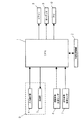
図1は本発明の車載用入力装置の一実施形態のシステム構成を示すブロック図、図2は図1に示された運転席用焦電センサ、助手席用焦電センサおよび操作装置の車内でのレイアウトの一例を示す斜視図、図3は図1に示されたCPUが行う処理の流れを示すフローチャート、図4は図1に示された表示部により表示される運転席用画面および助手席用画面の一例を示す図である。 FIG. 1 is a block diagram showing a system configuration of an embodiment of an in-vehicle input device according to the present invention. FIG. 2 is a diagram showing a driver's seat pyroelectric sensor, a passenger's seat pyroelectric sensor and an operating device shown in FIG. FIG. 3 is a flowchart showing a flow of processing performed by the CPU shown in FIG. 1, and FIG. 4 is a driver seat screen and a passenger seat displayed by the display unit shown in FIG. It is a figure which shows an example of a work screen.
図1に示すように、本実施形態は、CPU1および外部記憶装置2と、CPU1に操作信号を入力させるための操作装置3とを備えている。操作装置3は、CPU1に入力させる操作信号を生成して出力するタッチ‐パネルからなる入力操作部4と、CPU1によって制御される液晶表示装置からなる表示部5とを有している。
As shown in FIG. 1, the present embodiment includes a
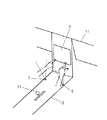
図2に示すように、操作装置3は、運転席(図示しない)および助手席(図示しない)のいずれの側からも操作できるように運転席と助手席との間、例えばインストルメント‐パネル11の上部中央に設けられている。
As shown in FIG. 2, the operating device 3 is provided between the driver seat and the passenger seat, for example, the
CPU1は、外部記憶装置2に予め記憶されているプログラムによって、自動車に搭載される車載機器、例えばエア‐コンディショナー8(以下「エアコン8」という)、オーディオ9およびナビゲーション‐システム10の動作に関する指令信号を、入力操作部4からの操作信号に応じて出力するようになっている。
The
また、図1に示すように、本実施形態は、運転席と入力操作部4との間における物体の存在を感知可能に設けられた運転席側光学式スイッチ、例えばオンオフ出力をする焦電センサからなる運転席側焦電センサ6と、助手席と入力操作部4との間における物体の存在を感知可能に設けられた助手席側光学式スイッチ、例えばオンオフ出力をする焦電センサからなる助手席側焦電センサ7とを備えている。
In addition, as shown in FIG. 1, the present embodiment is a driver-seat optical switch provided so as to be able to detect the presence of an object between the driver's seat and the
図2に示すように、運転席と助手席の間にはコンソール12が設けられている。運転席側焦電センサ6および助手席側焦電センサ7のそれぞれは、コンソール12上のシフトレバー13よりも前側で、運転席側の縁部および助手席側の縁部のそれぞれに設けられている。
As shown in FIG. 2, a
また、CPU1は、外部記憶装置2に予め記憶されているプログラムによって、運転席側焦電センサ6が物体の存在を感知したことを基に、運転席に座った運転者により入力操作部4が操作されると判定し、助手席側焦電センサ7が物体の存在を感知したことを基に、助手席に座った同乗者により入力操作部4が操作されると判定する判定部として機能するように設定されている。つまり、本実施形態では、入力操作部4が運転者により操作されるのか、同乗者により操作されるのかを判定する判定手段が、運転席側焦電センサ6と、助手席側焦電センサ7と、CPU1および外部記憶装置2とから構成されている。
Further, the
また、CPU1は、外部記憶装置2に予め記憶されているプログラムによって、入力操作部4に対して行われた操作に応じた操作画面を表示させる表示制御を、表示部5に対して行う表示制御部として機能するように設定されている。この表示制御部としてのCPU1は、判定部としての自身による判定結果が運転者により入力操作部4が操作されるという判定結果であるときに、図4(a)に示す運転席用画面20(操作画面)を表示させる表示制御を表示部5に対して行うように設定されている。さらに、同乗者により入力操作部4が操作されるという判定結果であるときに、図4(b)に示す助手席用画面40(操作画面)を表示させる表示制御を表示部5に対して行うように設定されている。
Further, the
運転席用画面20には、エアコン操作画面(図4(a)に示す画面)への切換えを指令するためのアイコン21と、オーディオ操作画面(図示しない)への切換えを指令するためのアイコン22と、エアコンの停止を指令するためのアイコン23と、風量を自動設定にすることを指令するためのアイコン24、風量設定値を指令するためのアイコン25〜28と、吹出口を指令するためのアイコン29〜33と、運転席側の温度設定値を示す表示領域34と、温度設定値を指令するためのアイコン35,36が表示されている。なお、運転席側画面20の背景色は例えば青色である。
The
助手席用画面40には、エアコン操作画面(図示しない)への切換えを指令するためのアイコン41と、オーディオ操作画面(図4(b)に示す画面)への切換えを指令するためのアイコン42と、メディアをCD,FM,AM,DVDのうちから選択するメディアを指令するためのアイコン43〜46と、CDまたはDVDを選択した場合の再生および一時停止、巻き戻し、および早送りのそれぞれを指令するためのアイコン47,48,49と、助手席側の温度設定値を示す表示領域50と、温度設定値を指令するためのアイコン51,52が表示されている。なお、助手席用画面40の背景色は運転席用画面20とは異なる色、例えば赤色である。
The
CPU1で行われる処理の流れは次のように設定されている。
The flow of processing performed by the
図3に示すように、CPU1はアクセサリスイッチがオンすると(手順S1でYSE)、運転席側焦電センサ6および助手席側焦電センサ7のそれぞれからの感知信号の入力状況の判定を行う(手順S2)。
As shown in FIG. 3, when the accessory switch is turned on (YSE in step S1), the
この手順S2での判定において、運転席側焦電センサ6からの感知信号を入力した場合には、助手席側焦電センサ7からの感知信号を入力したか否かに関係なく、運転席用入力モードに移行する(手順S3)。
In the determination in step S2, when a detection signal from the driver seat side
運転席用入力モードに移行したCPU1は、前述した図4(a)に示す運転席用画面20を表示させるとともに、入力操作部4からの操作信号に応じてデフォルトをもつアイコンを切り換えさせたり、画面がオーディオ操作画面に切り換えさせたりする表示制御を、表示部5に対して行う。さらに、入力操作部4からの操作信号に応じて、エアコン8やオーディオ9の動作に関する指令信号を生成し出力する。
The
また、手順S2での判定において、運転席側焦電センサ6からの感知信号を入力していない状態で、助手席側焦電センサ7からの感知信号を入力した場合には、助手席用入力モードに移行する(手順S4)。
Further, in the determination in step S2, if the sensing signal from the passenger seat side
助手席用入力モードに移行したCPU1は、前述した図4(b)に示す運転席用画面20を表示させるとともに、入力操作部4からの操作信号に応じてアイコンを切り換えさせたり、画面をエアコン操作画面に切り換えさせたりする表示制御を、表示部5に対して行う。さらに、入力操作部4からの操作信号に応じて、オーディオ9やエアコン8の動作に関する指令信号を生成し出力する。
The
CPU1は運転席側入力モードや助手席側入力モードに移行したのち、アクセサリスイッチがオフになっていれば、処理を手順S2に戻して判定ルーチンを繰り返し(手順S6でYES→手順S2)、アクセサリスイッチがオフになるとフローを終了させる。
After the
このように構成された本実施形態の動作について説明する。 The operation of the present embodiment configured as described above will be described.
運転者が入力操作部4に手を伸ばすと、この行為を運転席側焦電センサ6が感知して感知信号をCPU1に出力する。この感知信号を入力したCPU1は、運転席用入力モードに移行して表示部5の制御を行う。これにより、表示部5は、図4(a)に示す運転席用画面20を表示する。
When the driver reaches the
引き続き、運転者が入力操作部4を操作して、この入力操作部4からCPU1に操作信号が出力されると、CPU1はその操作信号を入力して、その操作信号に応じた表示制御を表示部5に対して行う。これにより、運転者が行う入力操作部4の操作に応じて運転席用画面20が変化する。また、CPU1は表示部5に対する表示制御と並行して、エアコン8やオーディオ9の動作に関する指令信号を、操作信号に応じて生成し出力する。
Subsequently, when the driver operates the
また、助手席の同乗者のみが入力操作部4に手を伸ばすと、この行為を助手席側焦電センサ7が感知して感知信号をCPU1に出力する。この感知信号を入力したCPU1は、助手席用入力モードに移行して表示部5の制御を行う。これにより、表示部5は、図4(b)に示す助手席用画面40を表示する。
When only the passenger in the passenger seat reaches the
引き続き、同乗者が入力操作部4を操作して、この入力操作部4からCPU1に操作信号が出力されると、CPU1はその操作信号を入力して、その操作信号に応じた表示制御を表示部5に対して行う。これにより、同乗者が行う入力操作部4の操作に応じて助手席用画面40が変化する。また、CPU1は表示部5に対する表示制御と並行して、エアコン8やオーディオ9の動作を指令する指令信号を、操作信号に応じて生成し出力する。
Subsequently, when the passenger operates the
なお、運転者と同乗者の両者が入力操作部4に手を伸ばした場合、運転席側焦電センサ6と助手席側焦電センサ7の両方からの感知信号をCPU1が入力することになるが、この場合には、CPU1は運転席用入力モードに移行する。
When both the driver and the passenger reach for the
本実施形態によれば次の効果を得られる。 According to this embodiment, the following effects can be obtained.
本実施形態では、運転席側焦電センサ6および助手席側焦電センサ7を備えている。これらの焦電センサ6,7は赤外線カメラよりも簡単な構成である。また、本実施形態は、入力操作部4が運転者により操作されるのか、助手席に座った同乗者により操作されるのかの判定を、運転席側焦電センサ6および助手席側焦電センサ7のどちらで物体が感知されたか否かによって行うので、その判定を行わせるためのプログラムのアルゴリズムが、画像処理プログラムのアルゴリズムよりも簡単である。これらのことから、本実施形態によれば、運転席と助手席との間に設置された入力操作部4が、運転席に座った運転者により操作されるのか、助手席に座った同乗者により操作されるのかを、簡単な構成で判定することができる。したがって、入力操作部4が運転者により操作されるのか同乗者により操作されるのかを判定する機能を有した車載用入力装置の製作コストの低減に貢献できる。
In the present embodiment, a driver seat side
また、本実施形態では、CPU1(判定部)が、運転席側焦電センサ6と助手席側焦電センサとの両方により同時に物体が感知された場合に、運転者により入力操作部4が操作されると判定するように設定されている。これにより、運転者と同乗者が同時に入力操作部4を操作しようとしたとき、入力操作部4の操作者として同乗者よりも運転者を優先させることができる。
In the present embodiment, the CPU 1 (determination unit) operates the
また、本実施形態では、操作画面の背景色がCPU1(判定部)による判定結果に応じて変化するので、操作者と判定された者が運転者と同乗者のどちらであるかを、操作画面の背景色を見て確認できる。 In this embodiment, since the background color of the operation screen changes according to the determination result by the CPU 1 (determination unit), it is determined whether the person who is determined as the operator is the driver or the passenger. You can see the background color.
なお、本実施形態は、運転席側光学式スイッチおよび助手席側光学式スイッチとしてオンオフ出力をする焦電センサを備えている例であったが、本発明に備えられる運転席側光学式スイッチおよび助手席側光学式スイッチは焦電センサに限るものではなく、反射型光電スイッチでもよい。 In addition, although this embodiment was an example provided with the pyroelectric sensor which performs an on-off output as a driver's seat side optical switch and a passenger's seat side optical switch, the driver's seat side optical switch provided in the present invention and The passenger-side optical switch is not limited to the pyroelectric sensor, but may be a reflective photoelectric switch.
1 CPU
2 外部記憶装置
3 操作装置
4 入力操作部
5 表示部
6 運転席側焦電センサ
7 助手席側焦電センサ
8 エア‐コンコンディショナー
9 オーディオ
10 ナビゲーション‐システム
11 インストルメント‐パネル
12 コンソール
20 運転席用画面
40 助手席用画面
1 CPU
2 External storage device 3
Claims (3)
この入力操作部が運転席に座った運転者により操作されるのか、助手席に座った同乗者により操作されるのかを判定する判定手段とを備えた車載用入力装置であって、
前記判定手段が、
前記運転席と前記入力操作部との間における物体の存在を感知可能に設けられた運転席側光学式スイッチと、
前記助手席と前記入力操作部との間における物体の存在を感知可能に設けられた助手席側光学式スイッチと、
運転席側光学式スイッチが物体の存在を感知したことを基に前記運転者により前記入力操作部が操作されると判定し、前記助手席側光学式スイッチが物体の存在を感知したことを基に前記同乗者により前記入力操作部が操作されると判定する判定部とから構成されていることを特徴とする車載用入力装置。 An input operation unit installed between the driver seat and the passenger seat;
A vehicle-mounted input device comprising: a determination unit that determines whether the input operation unit is operated by a driver sitting in a driver seat or a passenger sitting in a passenger seat;
The determination means is
A driver-seat-side optical switch provided so as to be able to detect the presence of an object between the driver's seat and the input operation unit;
An optical switch on the passenger seat side provided to be able to sense the presence of an object between the passenger seat and the input operation unit;
Based on the fact that the driver-side optical switch senses the presence of an object, it is determined that the driver operates the input operation unit, and the passenger-side optical switch senses the presence of an object. And a determination unit for determining that the input operation unit is operated by the passenger.
前記判定部は、運転席側光学式スイッチと助手席側光学式スイッチとの両方により同時に物体の存在が感知された場合に、前記運転者により前記入力操作部が操作されると判定するように設定されていることを特徴とする車載用入力装置。 In the invention of claim 1,
The determination unit determines that the driver operates the input operation unit when the presence of an object is simultaneously detected by both the driver side optical switch and the passenger side optical switch. An in-vehicle input device that is set.
操作画面を表示可能な表示部と、前記入力操作部に対して行われた操作に応じた操作画面を表示させる表示制御を、前記表示部に対して行う表示制御部とを備えていて、
前記判定部による判定結果が前記運転者により前記入力操作部が操作されるという判定結果であるときと、前記同乗者により前記入力操作部が操作されるという判定結果であるときとでは、背景色の異なる操作画面を表示させる表示制御を前記表示部に対して行うように、前記表示制御部が設定されていることを特徴とする車載用入力装置。
In the invention of claim 1,
A display unit capable of displaying an operation screen, and a display control unit that performs display control on the display unit to display an operation screen according to an operation performed on the input operation unit,
When the determination result by the determination unit is a determination result that the input operation unit is operated by the driver, and when the determination result that the input operation unit is operated by the passenger is a background color The in-vehicle input device is characterized in that the display control unit is set so that display control for displaying different operation screens is performed on the display unit.
Priority Applications (2)
| Application Number | Priority Date | Filing Date | Title |
|---|---|---|---|
| JP2006134132A JP2007302154A (en) | 2006-05-12 | 2006-05-12 | On-vehicle input device |
| EP07009334A EP1854678A1 (en) | 2006-05-12 | 2007-05-09 | On-vehicle input apparatus |
Applications Claiming Priority (1)
| Application Number | Priority Date | Filing Date | Title |
|---|---|---|---|
| JP2006134132A JP2007302154A (en) | 2006-05-12 | 2006-05-12 | On-vehicle input device |
Publications (1)
| Publication Number | Publication Date |
|---|---|
| JP2007302154A true JP2007302154A (en) | 2007-11-22 |
Family
ID=38361153
Family Applications (1)
| Application Number | Title | Priority Date | Filing Date |
|---|---|---|---|
| JP2006134132A Withdrawn JP2007302154A (en) | 2006-05-12 | 2006-05-12 | On-vehicle input device |
Country Status (2)
| Country | Link |
|---|---|
| EP (1) | EP1854678A1 (en) |
| JP (1) | JP2007302154A (en) |
Cited By (3)
| Publication number | Priority date | Publication date | Assignee | Title |
|---|---|---|---|---|
| JP2011170598A (en) * | 2010-02-18 | 2011-09-01 | Rohm Co Ltd | Touch panel input device |
| US9250800B2 (en) | 2010-02-18 | 2016-02-02 | Rohm Co., Ltd. | Touch-panel input device |
| WO2020026402A1 (en) * | 2018-08-02 | 2020-02-06 | 三菱電機株式会社 | On-vehicle information device and linking method with mobile terminal |
Families Citing this family (4)
| Publication number | Priority date | Publication date | Assignee | Title |
|---|---|---|---|---|
| US9477332B2 (en) * | 2014-03-24 | 2016-10-25 | Ford Global Technologies, Llc | System and method for enabling touchscreen by passenger in moving vehicle |
| DE102014016222A1 (en) * | 2014-10-31 | 2016-05-04 | Audi Ag | Method and system for operating a touch-sensitive display device of a motor vehicle |
| DE102016202251A1 (en) | 2016-02-15 | 2017-08-17 | Volkswagen Aktiengesellschaft | Arrangement, means of transport and method for assisting a user in operating a touch-sensitive display device |
| CN106095267A (en) * | 2016-06-01 | 2016-11-09 | 惠州市德赛西威汽车电子股份有限公司 | Mobile unit control method based on user view identification and system thereof |
Citations (4)
| Publication number | Priority date | Publication date | Assignee | Title |
|---|---|---|---|---|
| JPS631988A (en) * | 1985-12-25 | 1988-01-06 | Kazumi Meguro | Back sensor of car |
| JPH08184449A (en) * | 1994-12-28 | 1996-07-16 | Aqueous Res:Kk | Operation limiting device |
| JP2006064547A (en) * | 2004-08-27 | 2006-03-09 | Victor Co Of Japan Ltd | Navigation device for vehicle |
| JP2006072854A (en) * | 2004-09-03 | 2006-03-16 | Matsushita Electric Ind Co Ltd | Input device |
Family Cites Families (7)
| Publication number | Priority date | Publication date | Assignee | Title |
|---|---|---|---|---|
| US6166625A (en) * | 1996-09-26 | 2000-12-26 | Donnelly Corporation | Pyroelectric intrusion detection in motor vehicles |
| DE10041895A1 (en) * | 1999-08-31 | 2001-04-19 | Denso Corp | Trunk lock in rescue apparatus for vehicle, consists of detector to judge whether person is locked in trunk, based on which trunk opener, releases latch condition of lock |
| KR20020089414A (en) * | 2000-03-28 | 2002-11-29 | 지멘스 악티엔게젤샤프트 | Device and method for detecting an object or a person in the passenger compartment of a vehicle |
| JP2002133401A (en) * | 2000-10-18 | 2002-05-10 | Tokai Rika Co Ltd | Operator-discriminating method and operator- discriminating device |
| JP2004067031A (en) | 2002-08-08 | 2004-03-04 | Nissan Motor Co Ltd | Operator determining device and on-vehicle device using the same |
| DE10339314B3 (en) * | 2003-08-27 | 2005-04-21 | Fraunhofer-Gesellschaft zur Förderung der angewandten Forschung e.V. | Method for display control of different information in a vehicle and opto-acoustic information unit |
| JP4311190B2 (en) * | 2003-12-17 | 2009-08-12 | 株式会社デンソー | In-vehicle device interface |
-
2006
- 2006-05-12 JP JP2006134132A patent/JP2007302154A/en not_active Withdrawn
-
2007
- 2007-05-09 EP EP07009334A patent/EP1854678A1/en not_active Withdrawn
Patent Citations (4)
| Publication number | Priority date | Publication date | Assignee | Title |
|---|---|---|---|---|
| JPS631988A (en) * | 1985-12-25 | 1988-01-06 | Kazumi Meguro | Back sensor of car |
| JPH08184449A (en) * | 1994-12-28 | 1996-07-16 | Aqueous Res:Kk | Operation limiting device |
| JP2006064547A (en) * | 2004-08-27 | 2006-03-09 | Victor Co Of Japan Ltd | Navigation device for vehicle |
| JP2006072854A (en) * | 2004-09-03 | 2006-03-16 | Matsushita Electric Ind Co Ltd | Input device |
Cited By (4)
| Publication number | Priority date | Publication date | Assignee | Title |
|---|---|---|---|---|
| JP2011170598A (en) * | 2010-02-18 | 2011-09-01 | Rohm Co Ltd | Touch panel input device |
| US9250800B2 (en) | 2010-02-18 | 2016-02-02 | Rohm Co., Ltd. | Touch-panel input device |
| US9760280B2 (en) | 2010-02-18 | 2017-09-12 | Rohm Co., Ltd. | Touch-panel input device |
| WO2020026402A1 (en) * | 2018-08-02 | 2020-02-06 | 三菱電機株式会社 | On-vehicle information device and linking method with mobile terminal |
Also Published As
| Publication number | Publication date |
|---|---|
| EP1854678A1 (en) | 2007-11-14 |
Similar Documents
| Publication | Publication Date | Title |
|---|---|---|
| US8700309B2 (en) | Multiple visual display device and vehicle-mounted navigation system | |
| JP4758087B2 (en) | Display device | |
| KR101470031B1 (en) | Operation device for vehicle | |
| JP2007302154A (en) | On-vehicle input device | |
| JP2007310496A (en) | Touch operation input device | |
| JP6269343B2 (en) | Vehicle control device | |
| JP5397887B2 (en) | Vehicle monitoring system | |
| JP6274035B2 (en) | Vehicle display control device and vehicle display system | |
| JP6515028B2 (en) | Vehicle control device | |
| JP6464869B2 (en) | Operation system | |
| JP7147169B2 (en) | vehicle display | |
| US10317996B2 (en) | Operation system | |
| JP2009129251A (en) | Operation input apparatus | |
| JP6156052B2 (en) | Information processing apparatus for vehicle | |
| WO2016152044A1 (en) | Operation system | |
| KR101946746B1 (en) | Positioning of non-vehicle objects in the vehicle | |
| JP2008195141A (en) | Operation supporting device and method for on-vehicle equipment | |
| WO2019138663A1 (en) | Vehicle steering switch system, switch function switching program, and storage medium | |
| JP2008265544A (en) | On-vehicle touch panel | |
| JP2008014871A (en) | On-vehicle electronic device | |
| JP2021102357A (en) | On-vehicle equipment operation device | |
| JP2005313722A (en) | Operation display device of on-vehicle equipment and operation display method thereof | |
| JP2005156257A (en) | Input device for vehicle | |
| JP5146691B2 (en) | Remote control device | |
| JP5234608B2 (en) | Operating parameter setting device and operating parameter setting method |
Legal Events
| Date | Code | Title | Description |
|---|---|---|---|
| A621 | Written request for application examination |
Free format text: JAPANESE INTERMEDIATE CODE: A621 Effective date: 20080826 |
|
| A131 | Notification of reasons for refusal |
Free format text: JAPANESE INTERMEDIATE CODE: A131 Effective date: 20110419 |
|
| A977 | Report on retrieval |
Free format text: JAPANESE INTERMEDIATE CODE: A971007 Effective date: 20110421 |
|
| A761 | Written withdrawal of application |
Free format text: JAPANESE INTERMEDIATE CODE: A761 Effective date: 20110519 |