JP2007294737A - Tunnel magnetoresistance effect element, and magnetic memory cell and magnetic random access memory using the same - Google Patents
Tunnel magnetoresistance effect element, and magnetic memory cell and magnetic random access memory using the same Download PDFInfo
- Publication number
- JP2007294737A JP2007294737A JP2006122146A JP2006122146A JP2007294737A JP 2007294737 A JP2007294737 A JP 2007294737A JP 2006122146 A JP2006122146 A JP 2006122146A JP 2006122146 A JP2006122146 A JP 2006122146A JP 2007294737 A JP2007294737 A JP 2007294737A
- Authority
- JP
- Japan
- Prior art keywords
- film
- ferromagnetic
- ferromagnetic film
- tunnel magnetoresistive
- thickness
- Prior art date
- Legal status (The legal status is an assumption and is not a legal conclusion. Google has not performed a legal analysis and makes no representation as to the accuracy of the status listed.)
- Pending
Links
Images


Classifications
-
- H—ELECTRICITY
- H01—ELECTRIC ELEMENTS
- H01F—MAGNETS; INDUCTANCES; TRANSFORMERS; SELECTION OF MATERIALS FOR THEIR MAGNETIC PROPERTIES
- H01F10/00—Thin magnetic films, e.g. of one-domain structure
- H01F10/32—Spin-exchange-coupled multilayers, e.g. nanostructured superlattices
- H01F10/324—Exchange coupling of magnetic film pairs via a very thin non-magnetic spacer, e.g. by exchange with conduction electrons of the spacer
- H01F10/3254—Exchange coupling of magnetic film pairs via a very thin non-magnetic spacer, e.g. by exchange with conduction electrons of the spacer the spacer being semiconducting or insulating, e.g. for spin tunnel junction [STJ]
-
- B—PERFORMING OPERATIONS; TRANSPORTING
- B82—NANOTECHNOLOGY
- B82Y—SPECIFIC USES OR APPLICATIONS OF NANOSTRUCTURES; MEASUREMENT OR ANALYSIS OF NANOSTRUCTURES; MANUFACTURE OR TREATMENT OF NANOSTRUCTURES
- B82Y25/00—Nanomagnetism, e.g. magnetoimpedance, anisotropic magnetoresistance, giant magnetoresistance or tunneling magnetoresistance
-
- G—PHYSICS
- G11—INFORMATION STORAGE
- G11C—STATIC STORES
- G11C11/00—Digital stores characterised by the use of particular electric or magnetic storage elements; Storage elements therefor
- G11C11/02—Digital stores characterised by the use of particular electric or magnetic storage elements; Storage elements therefor using magnetic elements
- G11C11/16—Digital stores characterised by the use of particular electric or magnetic storage elements; Storage elements therefor using magnetic elements using elements in which the storage effect is based on magnetic spin effect
-
- H—ELECTRICITY
- H10—SEMICONDUCTOR DEVICES; ELECTRIC SOLID-STATE DEVICES NOT OTHERWISE PROVIDED FOR
- H10B—ELECTRONIC MEMORY DEVICES
- H10B61/00—Magnetic memory devices, e.g. magnetoresistive RAM [MRAM] devices
- H10B61/20—Magnetic memory devices, e.g. magnetoresistive RAM [MRAM] devices comprising components having three or more electrodes, e.g. transistors
- H10B61/22—Magnetic memory devices, e.g. magnetoresistive RAM [MRAM] devices comprising components having three or more electrodes, e.g. transistors of the field-effect transistor [FET] type
-
- H—ELECTRICITY
- H10—SEMICONDUCTOR DEVICES; ELECTRIC SOLID-STATE DEVICES NOT OTHERWISE PROVIDED FOR
- H10N—ELECTRIC SOLID-STATE DEVICES NOT OTHERWISE PROVIDED FOR
- H10N50/00—Galvanomagnetic devices
- H10N50/10—Magnetoresistive devices
-
- H—ELECTRICITY
- H01—ELECTRIC ELEMENTS
- H01F—MAGNETS; INDUCTANCES; TRANSFORMERS; SELECTION OF MATERIALS FOR THEIR MAGNETIC PROPERTIES
- H01F10/00—Thin magnetic films, e.g. of one-domain structure
- H01F10/32—Spin-exchange-coupled multilayers, e.g. nanostructured superlattices
- H01F10/324—Exchange coupling of magnetic film pairs via a very thin non-magnetic spacer, e.g. by exchange with conduction electrons of the spacer
- H01F10/3268—Exchange coupling of magnetic film pairs via a very thin non-magnetic spacer, e.g. by exchange with conduction electrons of the spacer the exchange coupling being asymmetric, e.g. by use of additional pinning, by using antiferromagnetic or ferromagnetic coupling interface, i.e. so-called spin-valve [SV] structure, e.g. NiFe/Cu/NiFe/FeMn
- H01F10/3272—Exchange coupling of magnetic film pairs via a very thin non-magnetic spacer, e.g. by exchange with conduction electrons of the spacer the exchange coupling being asymmetric, e.g. by use of additional pinning, by using antiferromagnetic or ferromagnetic coupling interface, i.e. so-called spin-valve [SV] structure, e.g. NiFe/Cu/NiFe/FeMn by use of anti-parallel coupled [APC] ferromagnetic layers, e.g. artificial ferrimagnets [AFI], artificial [AAF] or synthetic [SAF] anti-ferromagnets
Abstract
Description
本発明は、高い熱安定性を有する高出力トンネル磁気抵抗素子及びそれを装備した低消費電力不揮発性磁気メモリに関するものである。 The present invention relates to a high-power tunnel magnetoresistive element having high thermal stability and a low power consumption nonvolatile magnetic memory equipped with the same.
将来の高集積磁気メモリに適用されるトンネル磁気抵抗効果素子として、Alの酸化物を絶縁体に用いたトンネル磁気抵抗効果素子(T. Miyazaki and N. Tezuka, J. Magn. Magn. Mater. 139, L231 (1995))よりも数倍大きい磁気抵抗比が得られる絶縁膜に酸化マグネシウムを用いたトンネル磁気抵抗効果素子(S. Yuasa. et al., Nature Material 3, 868(2004))が開示されている。また、従来の不揮発性磁気メモリは、MOSFET上にトンネル磁気抵抗効果素子を形成したメモリセルにより構成される。スイッチングはMOSFETを利用し、ビット線とワード線に通電させることにより発生する電流誘起の空間磁場を使ってトンネル磁気抵抗効果素子の磁化方向を回転させ、情報を書込み、トンネル磁気抵抗効果素子の出力電圧により情報を読み出す方式である。また、上記電流誘起の空間磁場を使った磁化回転のほかに、直接磁気抵抗効果素子に電流を流すことにより磁化を回転させるいわゆるスピントランスファートルク磁化反転あるいは同義であるスピン注入磁化反転方式があり、例えば米国特許第5,695,864号明細書あるいは特開2002−305337号公報に開示されている。特開2005−294376には、外部からの侵入磁界に対して安定にスピントランスファートルク磁化反転動作させる目的で、非磁性膜を介して複数の強磁性膜を積層した自由層を適用したトンネル磁気抵抗効果素子が開示されている。 As a tunnel magnetoresistive element to be applied to highly integrated magnetic memories in the future, a tunnel magnetoresistive element using an oxide of Al as an insulator (T. Miyazaki and N. Tezuka, J. Magn. Magn. Mater. 139 , L231 (1995)), a tunnel magnetoresistive element using magnesium oxide as an insulating film (S. Yuasa. Et al., Nature Material 3, 868 (2004)) is disclosed. Has been. A conventional nonvolatile magnetic memory is constituted by a memory cell in which a tunnel magnetoresistive element is formed on a MOSFET. Switching uses a MOSFET to rotate the magnetization direction of the tunnel magnetoresistive element using the current-induced spatial magnetic field generated by energizing the bit line and the word line, write information, and output the tunnel magnetoresistive element This is a method of reading information by voltage. In addition to the magnetization rotation using the current-induced spatial magnetic field, there is a so-called spin transfer torque magnetization reversal or synonymous spin injection magnetization reversal method in which magnetization is rotated by passing a current directly through the magnetoresistive element, For example, it is disclosed in US Pat. No. 5,695,864 or JP-A-2002-305337. Japanese Patent Application Laid-Open No. 2005-294376 discloses a tunnel magnetoresistive using a free layer in which a plurality of ferromagnetic films are stacked via a nonmagnetic film for the purpose of stably performing a spin transfer torque magnetization reversal operation against an intruding magnetic field from the outside. An effect element is disclosed.
高い信頼性をもつ低消費電力不揮発性磁気メモリの実現には、高出力トンネル磁気抵抗効果素子の自由層(記録層)において高い熱安定性と、スピントランスファートルク磁化反転による書込み方式とを同時に満足する技術を開発する必要がある。 To realize a highly reliable and low power consumption nonvolatile magnetic memory, the free layer (recording layer) of the high-power tunnel magnetoresistive element simultaneously satisfies both high thermal stability and a writing method using spin transfer torque magnetization reversal. Need to develop technology.
本発明は、このような要請に応えることのできる高い熱安定性を有するトンネル磁気抵抗効果素子及びそれを用いた不揮発性磁気メモリを提供することを目的とする。 It is an object of the present invention to provide a tunnel magnetoresistive element having high thermal stability that can meet such a demand and a nonvolatile magnetic memory using the same.
本発明は、トンネル磁気抵抗効果素子の強磁性膜にBを含むCoあるいはFeの体心立方格子をもつ化合物強磁性膜を適用し、絶縁膜に(100)配向した岩塩構造酸化マグネシウムを適用し、強磁性自由層に非磁性層を挟んで反強磁性結合した二つの強磁性膜を適用する。すなわち、本発明によるトンネル磁気抵抗効果素子は、絶縁膜と、絶縁膜を挟んで設けられた強磁性自由層と強磁性固定層とを有し、絶縁膜は(100)配向した岩塩構造のMgO膜であり、強磁性自由層は、非磁性導電層を挟んで設けられた第一の強磁性膜と第二の強磁性膜からなり、第一の強磁性膜は絶縁膜に隣接し、第二の強磁性膜の磁化と第一の強磁性膜の磁化は反強磁性結合しており、強磁性膜固定層はCoとFeとBを含有する体心立方構造の膜を有する。 In the present invention, a compound ferromagnetic film having a body-centered cubic lattice of Co or Fe containing B is applied to a ferromagnetic film of a tunnel magnetoresistive effect element, and (100) -oriented rock salt structure magnesium oxide is applied to an insulating film. Two ferromagnetic films that are antiferromagnetically coupled with a nonmagnetic layer sandwiched between a ferromagnetic free layer are applied. That is, the tunnel magnetoresistive element according to the present invention has an insulating film, a ferromagnetic free layer and a ferromagnetic fixed layer provided between the insulating films, and the insulating film is a (100) -oriented rock salt structure MgO. The ferromagnetic free layer is composed of a first ferromagnetic film and a second ferromagnetic film provided with a nonmagnetic conductive layer in between, the first ferromagnetic film being adjacent to the insulating film, The magnetization of the second ferromagnetic film and the magnetization of the first ferromagnetic film are antiferromagnetically coupled, and the ferromagnetic film fixed layer has a body-centered cubic structure film containing Co, Fe, and B.
絶縁膜に(100)配向した岩塩構造のMgO膜を用いない場合には、磁気抵抗比は著しく低下し、磁気メモリセルあるいは磁気ランダムアクセスメモリに最低限必要な200mVの読み出し電圧が得られない。 When the MgO film having a (100) -oriented rock salt structure is not used as the insulating film, the magnetoresistance ratio is remarkably lowered, and the minimum read voltage of 200 mV required for the magnetic memory cell or magnetic random access memory cannot be obtained.
本発明のトンネル磁気抵抗効果素子は、磁気メモリセルや磁気ランダムアクセスメモリに適用することができる。 The tunnel magnetoresistive effect element of the present invention can be applied to a magnetic memory cell or a magnetic random access memory.
本発明によると、高い熱安定性を有するトンネル磁気抵抗効果素子が得られる。また、そのトンネル磁気抵抗効果素子を磁気メモリに装備することにより、高い熱安定性、すなわち磁気情報の保持時間の長い不揮発性メモリを実現することが可能である。 According to the present invention, a tunnel magnetoresistive element having high thermal stability can be obtained. In addition, by installing the tunnel magnetoresistive element in a magnetic memory, it is possible to realize a nonvolatile memory having high thermal stability, that is, a long magnetic information retention time.
以下、図面を参照して本発明の実施の形態を説明する。以下に述べるトンネル磁気抵抗効果素子では、その強磁性自由層の磁化反転(スイッチング)を空間的な外部磁界ではなく主として、トンネル磁気抵抗効果素子中を流れるスピン偏極した電流のスピンが強磁性自由層の磁気モーメントにトルクを与えることにより行う。このスピン偏極した電流は、トンネル磁気抵抗効果素子に電流を流すこと自体で発生する。したがって、トンネル磁気抵抗効果素子に外部から電流を流すことによりスピントランスファートルク磁化反転は実現される。以下では、スピントランスファートルク磁化反転の起こる電流密度の閾値をJcと定義した。 Embodiments of the present invention will be described below with reference to the drawings. In the tunnel magnetoresistive effect element described below, the magnetization reversal (switching) of the ferromagnetic free layer is mainly not a spatial external magnetic field, but the spin-polarized current spin flowing in the tunnel magnetoresistive effect element is ferromagnetic free. This is done by applying a torque to the magnetic moment of the layer. This spin-polarized current is generated by passing a current through the tunnel magnetoresistive element itself. Therefore, spin transfer torque magnetization reversal is realized by flowing a current from the outside to the tunnel magnetoresistive effect element. Hereinafter, the threshold value of the current density at which the spin transfer torque magnetization reversal occurs is defined as Jc.
[実施例1]
図1は、本発明によるトンネル磁気抵抗効果素子の一例を示す断面模式図である。本実施例では、トンネル磁気抵抗効果素子はスパッタリング法を用いて作製した。このトンネル磁気抵抗効果素子1は、配向制御膜300、反強磁性膜301、強磁性固定層3021、絶縁膜305、第一の強磁性膜306、第一の非磁性膜307、第二の強磁性膜308、保護膜309により形成され、適当な温度で熱処理することにより磁気抵抗比が最適化される。熱処理は、400℃まで行うことが可能である。強磁性固定層3021は、第四の強磁性膜302、第二の非磁性膜303、第三の強磁性膜304で構成される場合もある。以下、強磁性固定層3021が、第四の強磁性膜302、第二の非磁性膜303、第三の強磁性膜304で構成される場合について述べる。
[Example 1]
FIG. 1 is a schematic cross-sectional view showing an example of a tunnel magnetoresistive effect element according to the present invention. In this example, the tunnel magnetoresistive effect element was produced using a sputtering method. This tunnel
配向制御膜300はNiFe(5nm)により形成したが、Ta(5nm)/NiFe(5nm)の2層膜など、上記反強磁性膜301の配向性を向上させ、安定した反強磁性結合を実現することのできる他の材料を用いてもよい。反強磁性膜301にはMnIr(8nm)を用いたが、膜厚は5〜15nmの範囲で選択可能である。また、MnPt,MnFeなど、Mn化合物で構成される反強磁性膜を用いても安定に反強磁性結合を実現できる。第四の強磁性膜302にはCoFe(2nm)を、第二の非磁性膜303にはRu(0.8nm)を、第三の強磁性膜304には体心立方格子をもつCoFeB(3nm)を用いた。第四の強磁性膜302のCoFeの組成比は、Co組成を50〜90atm%の間とした。この組成範囲において、上記反強磁性膜と安定した反強磁性結合を実現できる。第四の強磁性膜302、第二の非磁性膜303、第三の強磁性膜304は、第四の強磁性膜302と第三の強磁性膜304の磁化が反強磁性結合するような材料を選択し、それぞれの膜厚は第四の強磁性膜302と第三の強磁性膜304の磁化の大きさが等しくなるように選択した。
Although the
絶縁膜305は、岩塩構造をもつ酸化マグネシウム結晶膜であり、(100)方向に配向した膜である。絶縁膜の膜厚は0.8nm〜3nmの範囲とした。絶縁膜305の膜厚を前記の範囲とすることにより、任意の電気抵抗を選択することが可能である。第二の強磁性膜308、第一の強磁性膜306は体心立方格子をもつCoFeB(3nm)を用いた。第一の強磁性膜306と第二の強磁性膜308のCoFeBのCoとFeの組成は50:50〜70:30の範囲とするのが好ましい。この組成範囲では図12に示すように体心立方構造が安定に存在し、かつ絶縁膜305にMgOを適用したトンネル磁気抵抗効果素子1では、CoをFeより多く含むことでトンネル磁気抵抗比に寄与するスピン分極率を向上できるためである。第一の非磁性膜307は、Ruを用い、その膜厚は第一の強磁性膜306と第二の強磁性膜308の磁化が反平行結合するように選択した。
The insulating film 305 is a magnesium oxide crystal film having a rock salt structure, and is a film oriented in the (100) direction. The thickness of the insulating film was in the range of 0.8 nm to 3 nm. Arbitrary electrical resistance can be selected by setting the thickness of the insulating film 305 within the above range. For the second
図3(a)は、第一の非磁性膜307の膜厚に対する第一の強磁性膜306と第二の強磁性膜308の磁化結合の強さを表す図である。図の磁化結合が正の領域は第一の強磁性膜306と第二の強磁性膜308が反平行結合していることを表し、負の領域は平行結合していることを表す。図3(b)は、第一の非磁性膜307の膜厚に対する書込み電流の大きさをプロットした図である。図3(b)から、図3(a)で示した反平行結合の膜厚領域において書込み電流が小さいことがわかり、第一の非磁性膜307の膜厚は0.4nmから1.4nmの範囲あるいは2.0nmから2.8nmの範囲を選択することが望ましい。
FIG. 3A is a diagram showing the strength of the magnetic coupling between the first
上記第三の強磁性膜304、第二の強磁性膜308及び第一の強磁性膜306のCoFeBは、非結晶であってもよく、適当な温度での熱処理により結晶化させてもよい。また、CoFeBの組成比は、体心立方格子が安定となるCo組成が40〜60atm%、B組成が10〜30atm%の間とすることが望ましい。さらに、第一の強磁性膜306、第二の強磁性膜308にはCoFeB以外に、CoFeの単層膜、NiFeの単層膜、CoFe/NiFeあるいはCoFeB/NiFeさらにCoFeB/CoFeの2層膜を用いてもよい。このときのCoFeのCo組成は体心立方格子が安定である50atm%が望ましいが、50〜90%の間で使用してよい。Co組成が大きいと、面心立方格子が安定であり、トンネル磁気抵抗比は減少するが、強磁性自由層として保磁力の小さい良好な磁気特性が実現でき、スピントランスファートルク磁化反転の閾値電流密度をそれぞれの磁気モーメントの大きさに対応して変化させることができる。保護膜300は、Ta(5nm)/Ru(5nm)の2層膜で形成した。
The CoFeB of the third
次に、素子加工プロセスについて述べる。素子加工にはフォトリソグラフィーとイオンミリングを用い、最小0.1μm×0.12μmの面積をもつトンネル磁気抵抗効果素子を作製した。このように作製されたトンネル磁気抵抗効果素子のトンネル磁気抵抗比は、熱処理を施すことにより増大させることが可能であり、第二の強磁性膜308と第一の強磁性膜306にCoFeBを用いた構成では、375℃以上で1時間程度の熱処理を施すことにより250%に達した。また、絶縁膜305の厚さが0.8nmから3.0nmの範囲では、100%以上のトンネル磁気抵抗比を示した。また、熱処理の温度は400℃まで上昇させても、150%以上の良好な磁気抵抗比を得ることが可能である。特に、熱処理によりCoFeBは結晶化することが確認され、結晶化した後のCoFeBが体心立方格子の結晶構造をもつ場合に、トンネル磁気抵抗比は最も大きくなった。
Next, the element processing process will be described. A tunnel magnetoresistive element having a minimum area of 0.1 μm × 0.12 μm was produced by photolithography and ion milling for element processing. The tunnel magnetoresistive ratio of the tunnel magnetoresistive effect element manufactured in this way can be increased by performing heat treatment, and CoFeB is used for the second
酸化マグネシウムの(100)配向膜は、非晶質の第三の強磁性膜の上にスパッタ法を用いて作製することは可能であるが、多結晶構造をもつ第三の強磁性膜の上にスパッタ法を用いて作製した場合、良好な(100)配向膜を得ることは困難であり、トンネル磁気抵抗比は最大でも50%にとどまった。このことは、第一の強磁性膜306と第三の強磁性膜304が結晶のCoFeBであり、かつ絶縁膜305が(100)配向の結晶の酸化マグネシウムであるトンネル磁気抵抗効果素子1で、200%以上のトンネル磁気抵抗比が得られている素子は、必ず製膜時の第一の強磁性膜306と第三の強磁性膜304は非結晶のCoFeBであって、熱処理の過程を経て作製されたものであることを示している。このように熱処理によりCoFeB膜を非晶質から結晶化させることにより高い磁気抵抗比を得ることが可能であるが、CoFeBを350℃以下の熱処理温度で非晶質の状態で使用してもかまわない。
The (100) -oriented film of magnesium oxide can be formed on the amorphous third ferromagnetic film by sputtering, but it is formed on the third ferromagnetic film having a polycrystalline structure. When a sputtering method is used, it is difficult to obtain a good (100) orientation film, and the tunnel magnetoresistance ratio is only 50% at the maximum. This is the tunnel magnetoresistive
上記のように、製膜時非晶質であった第一の強磁性膜306と第三の強磁性膜304を熱処理により結晶化させてトンネル磁気抵抗効果素子1を作製する方法は、従来の方法とは異なる。ただし、第一の強磁性膜306にCoFe単層膜、NiFe単層膜、CoFe/NiFe膜を使用したトンネル磁気抵抗効果素子1では、これらの第一の強磁性膜306は製膜時から結晶質であり、熱処理により第三の強磁性膜304のみが結晶化することになる。第一の強磁性膜306にCoFe単層膜、NiFe単層膜、CoFe/NiFe膜を使用したトンネル磁気抵抗効果素子1の最大のトンネル磁気抵抗比は、それぞれ、200%、40%、150%であった。
As described above, the method of fabricating the tunnel magnetoresistive
次に、第一の強磁性膜306の膜厚t1と第二の強磁性膜308の膜厚t2の選択について説明する。ここで、t1<t2を前提とする。t1>t2の場合は、スピントルク磁化反転の書込み電流Icの飛躍的な増大が起きる。
Next, selection of the film thickness t1 of the first
最初に、第一の強磁性膜306と第二の強磁性膜308の磁化の大きさ(それぞれ、M1、M2とする)がM1=M2と等しい場合について説明する。図4にはM1=M2=1.5Tの例について示す。この磁化の大きさはCoFeBやCoFeの値に相当するものである。図4(a)は第一の強磁性膜306の膜厚t1に対する第二の強磁性膜308の膜厚t2の比(t2/t1)とスピントルク磁化反転の閾値電流密度Jcの関係をプロットした図、図4(b)は膜厚比(t2/t1)と熱安定性の大きさを示すパラメータKV/kTの関係をプロットした図である。K,V,k、Tは物理パラメータであり、それぞれ一軸異方性定数、体積、ボルツマン定数、温度である。第一の強磁性膜306の膜厚t1はt1=1.5nm、2.0nm、3.0nmである。
First, the case where the magnitudes of magnetization of the first
図4(a)から、第二の強磁性膜308の膜厚t2が厚くなるにつれてJcは増大することがわかる。また、t1が薄くなるにつれてJcは低減する。一方、図4(b)から、熱安定性は、t1,t2がともに厚くなるにつれて増大することがわかる。ここで、一般に磁気メモリにはKV/kTの値が60以上の熱安定性が要求される。この値は記録が10年間保持されるための条件であり、現在のメモリ市場において必要十分な仕様とされている。その数値を満足するには、t1=1.5〜3.0nmの範囲においては、例えば、t1=3.0nmのときt2/t1>0.5、t1=2.0nmのときt2/t1>0.65、t1=1.5nmのときt2/t1>0.75を選択する必要がある。
FIG. 4A shows that Jc increases as the thickness t2 of the second
次に、第一の強磁性膜306と第二の強磁性膜308の磁化の大きさがM1<M2の場合について評価を行った。ここでは、M1=1.5T、M2=1Tとした。M=1Tは例えばNiFe膜が相当する。結果を図5に示す。図5には、図4と同様に、第一の強磁性膜の各膜厚t1に対する第二の強磁性膜の膜厚t2の比(t2/t1)に対して、スピントルク磁化反転の閾値電流密度Jcと熱安定性の大きさを示すパラメータKV/kTをプロットした。
Next, the case where the magnitude of magnetization of the first
図5から、M1<M2の場合も、図4に示した傾向と同様であることがわかる。すなわち、図5(a)から、t2が厚くなるにつれてJcは増大することがわかる。また、t1が薄くなるにつれてJcは低減する。ここで、Jcの絶対値については、図4に示したM1=M2の場合にくらべて低減する。一方、図5(b)から、熱安定性は、t1,t2がともに厚くなるにつれて増大することがわかる。上記と同様に磁気メモリとして必要とされている熱安定性としてKV/kTで60以上を仮定すると、その数値を満足するには、t1=1.5〜3.0nmの範囲においては、例えば、t1=3.0nmのときt2/t1>0.6、t1=2.0nmのときt2/t1>0.9であり、t1=1.5nmのときはKV/kT>60を実現するのは困難であった。 From FIG. 5, it can be seen that the case of M1 <M2 is the same as the tendency shown in FIG. That is, FIG. 5A shows that Jc increases as t2 becomes thicker. Further, Jc decreases as t1 becomes thinner. Here, the absolute value of Jc is reduced as compared with the case of M1 = M2 shown in FIG. On the other hand, it can be seen from FIG. 5B that the thermal stability increases as both t1 and t2 become thicker. Assuming that KV / kT is 60 or more as the thermal stability required for the magnetic memory similarly to the above, in order to satisfy the numerical value, in the range of t1 = 1.5 to 3.0 nm, for example, t2 / t1> 0.6 when t1 = 3.0 nm, t2 / t1> 0.9 when t1 = 2.0 nm, and KV / kT> 60 is achieved when t1 = 1.5 nm. It was difficult.
次に、M1<M2の場合についての結果を図6に示す。ここでは、M1=1T、M2=1.5Tとした。図6に、図4及び図5と同様に、第一の強磁性膜の各膜厚t1に対する第二の強磁性膜の膜厚t2の比(t2/t1)に対してJcと熱安定性の大きさを示すパラメータKV/kTをプロットした結果を示す。 Next, the result in the case of M1 <M2 is shown in FIG. Here, M1 = 1T and M2 = 1.5T. In FIG. 6, as in FIGS. 4 and 5, Jc and thermal stability with respect to the ratio (t2 / t1) of the thickness t2 of the second ferromagnetic film to the thickness t1 of the first ferromagnetic film. The result of plotting the parameter KV / kT indicating the magnitude of the is shown.
これらの結果も前述した図4,5の傾向と同様であることがわかる。図6(a)から、t2が厚くなるにつれてJcは増大することがわかる。また、t1が薄くなるにつれてJcは低減する。ここで、Jcの絶対値については、図4、5に示した場合に比べて特にt2/t1<0.5の範囲において低減する。一方、図6(b)から、熱安定性は、t1,t2がともに厚くなるにつれて増大することがわかる。上記と同様に磁気メモリとして必要とされている熱安定性KV/kT>60の数値を満足するには、t1=1.5〜3.0nmの範囲においては、例えば、t1=3.0nmのときt2/t1>0.35、t1=2.0nmのときt2/t1>0.45、t1=1.5nmのときt2/t1>0.5を選択する必要がある。 It can be seen that these results are also similar to the above-described tendency of FIGS. FIG. 6A shows that Jc increases as t2 becomes thicker. Further, Jc decreases as t1 becomes thinner. Here, the absolute value of Jc is reduced particularly in the range of t2 / t1 <0.5 as compared with the cases shown in FIGS. On the other hand, it can be seen from FIG. 6B that the thermal stability increases as both t1 and t2 become thicker. In order to satisfy the numerical value of the thermal stability KV / kT> 60 required for the magnetic memory as described above, in the range of t1 = 1.5 to 3.0 nm, for example, t1 = 3.0 nm It is necessary to select t2 / t1> 0.35, t2 / t1> 0.45 when t1 = 2.0 nm, and t2 / t1> 0.5 when t1 = 1.5 nm.
次に、M1=M2=1Tの場合についての結果を図7に示す。図7に、第一の強磁性膜の各膜厚t1に対する第二の強磁性膜の膜厚t2の比(t2/t1)に対してスピントルク磁化反転の閾値電流密度Jcと熱安定性の大きさを示すパラメータKV/kTをプロットした結果を示す。 Next, the result in the case of M1 = M2 = 1T is shown in FIG. FIG. 7 shows the threshold current density Jc of spin torque magnetization reversal and thermal stability with respect to the ratio (t2 / t1) of the film thickness t2 of the second ferromagnetic film to the film thickness t1 of the first ferromagnetic film. The result of having plotted the parameter KV / kT which shows a magnitude | size is shown.
これらの結果も前述した図4から図6の傾向と同様であることがわかる。図7(a)から、t2が厚くなるにつれてJcは増大することがわかる。また、t1が薄くなるにつれてJcは低減する。ここで、Jcの絶対値については、図4、図5、図6に示した場合にくらべて低減する。一方、図7(b)から、熱安定性は、t1,t2がともに厚くなるにつれて増大することがわかる。磁気メモリとして必要とされている安定性KV/kT>60の数値を満足するには、t1=1.5〜3.0nmの範囲においては、例えば、t1=3.0nmのときt2/t1>0.5、t1=2.0nmのときt2/t1>0.65、t1=1.5nmのときt2/t1>0.75を選択する必要がある。 It can be seen that these results are also similar to the above-described tendency of FIGS. FIG. 7A shows that Jc increases as t2 becomes thicker. Further, Jc decreases as t1 becomes thinner. Here, the absolute value of Jc is reduced as compared with the cases shown in FIGS. On the other hand, it can be seen from FIG. 7B that the thermal stability increases as both t1 and t2 become thicker. In order to satisfy the numerical value of stability KV / kT> 60 required for a magnetic memory, in the range of t1 = 1.5 to 3.0 nm, for example, t2 / t1> when t1 = 3.0 nm. It is necessary to select t2 / t1> 0.65 when 0.5 and t1 = 2.0 nm, and t2 / t1> 0.75 when t1 = 1.5 nm.
上例のようにM1,M2はそれぞれ第一の強磁性膜及び第二の強磁性膜の磁化の大きさを与えるが、例えば、第一の強磁性膜がCoFe/NiFe、CoFeB/NiFeさらにCoFeB/CoFeのように2層により構成される場合、これらのトータルの磁化の大きさとしてCoFe,NiFe及びCoFeBの各膜厚が設定される。また、CoFe,NiFe,CoFeBの単層膜を第一の強磁性膜、第二の強磁性膜として適用してもよい。 As in the above example, M1 and M2 give the magnitudes of magnetization of the first ferromagnetic film and the second ferromagnetic film, respectively. For example, the first ferromagnetic film has CoFe / NiFe, CoFeB / NiFe, and CoFeB. In the case of two layers such as / CoFe, the respective film thicknesses of CoFe, NiFe, and CoFeB are set as the magnitude of the total magnetization. Further, a single layer film of CoFe, NiFe, and CoFeB may be applied as the first ferromagnetic film and the second ferromagnetic film.
[実施例2]
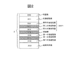
図2は、本発明によるトンネル磁気抵抗効果素子の他の例を示す断面模式図である。このトンネル磁気抵抗効果素子2は、配向制御膜300、第二の強磁性膜308、第一の非磁性膜307、第一の強磁性膜306、絶縁膜305、強磁性固定層3021、反強磁性膜301、保護膜309により形成される。特に第一の強磁性膜306及び第三の強磁性膜304にCoFeBを用いた場合、その結晶構造は体心立方格子であり、絶縁膜305は(100)に高配向した岩塩構造をもつMgOである。さらに、第一の強磁性膜306、第一の非磁性膜307、第二の強磁性膜308の3層でトンネル磁気抵抗効果素子2の自由層が形成される。強磁性固定層3021は、第四の強磁性膜302、第二の非磁性膜303、第三の強磁性膜304で構成される場合もある。以下、強磁性固定層3021が、第四の強磁性膜302、第二の非磁性膜303、第三の強磁性膜304で構成される場合について述べる。
[Example 2]
FIG. 2 is a schematic cross-sectional view showing another example of the tunnel magnetoresistive effect element according to the present invention. The tunnel magnetoresistive
本構成のトンネル磁気抵抗効果素子2では、第二の強磁性膜308は、配向制御膜300に隣接して作製され、さらにその上に第一の非磁性膜307、第一の強磁性膜306が作製されるため、平坦性に優れている。したがって、実施例1の構造に比べて第一の強磁性膜307の軟磁気特性が向上し、第一の強磁性膜306、第一の非磁性膜307、第二の強磁性膜308の3層で形成される自由層の磁気特性が改善できる。例えば、結晶化した後のCoFeBの磁化曲線の角型比が改善され、スピントルク磁化反転におけるスイッチングが円滑に起こる。絶縁膜305も平坦な膜に形成される。しかし、反強磁性膜301がトンネル磁気抵抗効果素子2の積層方向の上方に製膜されるため、当該膜の配向性が実施例1に比べ劣化するため第四の強磁性膜との間に働く反強磁性結合が弱くなり、実施例1に比べ耐熱処理特性が劣化し、400℃の熱処理によりトンネル磁気抵抗比は減少する傾向を示す。トンネル磁気抵抗効果素子2の作製方法、それぞれの膜に使用した材料は実施例1と同様である。また、このトンネル磁気抵抗効果素子2によって得られた磁気抵抗比は、実施例1とほぼ同様の200%であった。
In the tunnel magnetoresistive
本実施例においての第一の強磁性膜306と第二の強磁性膜308の各厚の選択については、図4から図7に述べた方法と同様である。
Selection of the thicknesses of the first
ここで、実施例1と実施例2における第一の強磁性膜306と第二の強磁性膜308の材料選択と図4から図7に示した膜厚の比に対して得られた結果の対応を図8と図9に表にまとめて記載した。図8は、第一の強磁性膜306に単層膜を使用した場合、図9は第一の強磁性膜に306に2層の強磁性膜を使用した場合について示した。上記のトンネル磁気抵抗効果素子と以下の磁気メモリセル及び磁気ランダムアクセスメモリを構成するトンネル磁気抵抗素子の第一の強磁性膜306と第二の強磁性膜308は図8と図9に示した材料を使用することが可能である。
Here, the results obtained with respect to the material selection of the first
[実施例3]
図10は、本発明による磁気メモリセルの構成例を示す断面模式図である。この磁気メモリセルは、メモリセルとして実施例1、2に示したトンネル磁気抵抗効果素子10を搭載している。
[Example 3]
FIG. 10 is a schematic cross-sectional view showing a configuration example of a magnetic memory cell according to the present invention. This magnetic memory cell is equipped with the tunnel magnetoresistive
C−MOS11は、2つのn型半導体12,13と一つのp型半導体14からなる。n型半導体12にドレインとなる電極21が電気的に接続され、電極41及び電極47を介してグラウンドに接続されている。n型半導体13には、ソースとなる電極22が電気的に接続されている。さらに23はゲート電極であり、このゲート電極23のon/offによりソース電極22とドレイン電極21の間の電流のON/OFFを制御する。上記ソース電極22に電極45、電極44、電極43、電極42、電極46が積層され、電極46を介してトンネル磁気抵抗効果素子10の配向制御膜300が接続されている。
The C-
ビット線212は上記トンネル磁気抵抗効果素子10の保護膜309に接続されている。本実施例の磁気メモリセルでは、トンネル磁気抵抗効果素子10に流れる電流、いわゆるスピントランスファートルクによりトンネル磁気抵抗効果素子10の第一の強磁性膜306と第一の非磁性膜307と第二の強磁性膜308で構成される強磁性自由層の磁化方向を回転し磁気的情報を記録する。スピントランスファートルクは空間的な外部磁界ではなく主として、トンネル磁気抵抗効果素子中を流れるスピン偏極した電流のスピンが前記トンネル磁気抵抗効果素子の強磁性自由層の磁気モーメントにトルクを与える原理である。このスピン偏極した電流はトンネル磁気抵抗効果素子に電流を流すこと自身で発生するメカニズムをもつ。したがって、トンネル磁気抵抗効果素子に外部から電流を供給する手段を備え、その手段から電流を流すことによりスピントランスファートルク磁化反転は実現される。本実施例では、ビット線212と電極46の間に電流が流れることによりトンネル磁気抵抗効果素子10中の第一の強磁性膜306と第二の強磁性膜308で構成される強磁性自由層にスピントランスファートルクが作用する。スピントランスファートルクにより書込みを行った場合、書込み時の電力は電流磁界を用いた場合に比べ百分の一程度まで低減可能である。
The
図11は、上記磁気メモリセルを配置した磁気ランダムアクセスメモリの構成例を示す図である。ゲート電極23とビット線212がメモリセル100に電気的に接続されている。前記実施例に記載した磁気メモリセルを配置することにより前記磁気メモリは低消費電力で動作が可能であり、ギガビット級の高密度磁気メモリを実現可能である。
FIG. 11 is a diagram showing a configuration example of a magnetic random access memory in which the magnetic memory cells are arranged. The
1…トンネル磁気抵抗効果素子、2…トンネル磁気抵抗効果素子、10…トンネル磁気抵抗効果素子、100…トンネル磁気抵抗効果素子、11…トランジスタ、12…第一のn型半導体、13…第二のn型半導体、14…p型半導体、21…ソース電極、212…ビット線、22…ドレイン電極、23…ゲート電極、300…配向制御膜、301…反強磁性膜、3021…強磁性固定層、302…第四の強磁性膜、303…第二の非磁性膜、304…第三の強磁性膜、305…絶縁膜、306…第一の強磁性膜、307…第一の非磁性膜、308…第二の強磁性膜、309…保護膜、41…電極配線、42…電極配線、43…電極配線、44…電極配線、45…電極配線、46…電極配線
DESCRIPTION OF
Claims (15)
前記絶縁膜は(100)配向した岩塩構造のMgO膜であり、
前記強磁性自由層は、非磁性導電層を挟んで設けられた第一の強磁性膜と第二の強磁性膜からなり、前記第一の強磁性膜は前記絶縁膜に隣接し、前記第二の強磁性膜と第一の強磁性膜は反強磁性結合しており、
前記強磁性膜固定層はCoとFeとBを含有する体心立方構造の膜を有することを特徴とするトンネル磁気抵抗効果素子。 An insulating film, and a ferromagnetic free layer and a ferromagnetic pinned layer sandwiched between the insulating films,
The insulating film is a MgO film having a (100) -oriented rock salt structure,
The ferromagnetic free layer comprises a first ferromagnetic film and a second ferromagnetic film provided with a nonmagnetic conductive layer interposed therebetween, the first ferromagnetic film being adjacent to the insulating film, The second ferromagnetic film and the first ferromagnetic film are antiferromagnetically coupled,
2. The tunnel magnetoresistive element according to claim 1, wherein the ferromagnetic film fixed layer has a body-centered cubic structure film containing Co, Fe, and B.
前記強磁性自由層をスピントランスファートルクにより磁化反転させるための電流を前記トンネル磁気抵抗効果素子に流す電極と、
前記トンネル磁気抵抗効果素子に流れる電流をオン・オフ制御するスイッチング素子とを備えることを特徴とする磁気メモリセル。 An insulating film, and a ferromagnetic free layer and a ferromagnetic pinned layer sandwiched between the insulating films, the insulating film being a (100) -oriented rock salt structure MgO film, A first ferromagnetic film and a second ferromagnetic film provided with a nonmagnetic conductive layer interposed therebetween, wherein the first ferromagnetic film is adjacent to the insulating film, and the second ferromagnetic film The first ferromagnetic film is antiferromagnetically coupled, and the ferromagnetic film pinned layer includes a tunnel magnetoresistive element having a body-centered cubic structure film containing Co, Fe, and B;
An electrode for passing a current to invert the magnetization of the ferromagnetic free layer by spin transfer torque to the tunnel magnetoresistive element;
A magnetic memory cell comprising: a switching element that controls on / off of a current flowing through the tunnel magnetoresistive element.
前記磁気メモリセルは、
絶縁膜と、前記絶縁膜を挟んで設けられた強磁性自由層と強磁性固定層とを有し、前記絶縁膜は(100)配向した岩塩構造のMgO膜であり、前記強磁性自由層は、非磁性導電層を挟んで設けられた第一の強磁性膜と第二の強磁性膜からなり、前記第一の強磁性膜は前記絶縁膜に隣接し、前記第二の強磁性膜と第一の強磁性膜は反強磁性結合しており、前記強磁性膜固定層はCoとFeとBを含有する体心立方構造の膜を有するトンネル磁気抵抗効果素子と、
前記強磁性自由層をスピントランスファートルクにより磁化反転させるための電流を前記トンネル磁気抵抗効果素子に流す電極と
を有することを特徴とする磁気ランダムアクセスメモリ。 A plurality of magnetic memory cells, and means for selecting a desired magnetic memory cell,
The magnetic memory cell is
An insulating film, and a ferromagnetic free layer and a ferromagnetic pinned layer sandwiched between the insulating films, the insulating film being a (100) -oriented rock salt structure MgO film, A first ferromagnetic film and a second ferromagnetic film provided with a nonmagnetic conductive layer interposed therebetween, wherein the first ferromagnetic film is adjacent to the insulating film, and the second ferromagnetic film The first ferromagnetic film is antiferromagnetically coupled, and the ferromagnetic film pinned layer includes a tunnel magnetoresistive element having a body-centered cubic structure film containing Co, Fe, and B;
A magnetic random access memory comprising: an electrode for passing a current for reversing the magnetization of the ferromagnetic free layer by a spin transfer torque to the tunnel magnetoresistive element.
Priority Applications (2)
| Application Number | Priority Date | Filing Date | Title |
|---|---|---|---|
| JP2006122146A JP2007294737A (en) | 2006-04-26 | 2006-04-26 | Tunnel magnetoresistance effect element, and magnetic memory cell and magnetic random access memory using the same |
| US11/739,956 US7894244B2 (en) | 2006-04-26 | 2007-04-25 | Tunnel magnetic resistance device, and magnetic memory cell and magnetic random access memory using the same |
Applications Claiming Priority (1)
| Application Number | Priority Date | Filing Date | Title |
|---|---|---|---|
| JP2006122146A JP2007294737A (en) | 2006-04-26 | 2006-04-26 | Tunnel magnetoresistance effect element, and magnetic memory cell and magnetic random access memory using the same |
Related Child Applications (1)
| Application Number | Title | Priority Date | Filing Date |
|---|---|---|---|
| JP2012181778A Division JP2013016820A (en) | 2012-08-20 | 2012-08-20 | Tunnel magnetoresistance effect element, and magnetic memory cell and random access memory including the same |
Publications (2)
| Publication Number | Publication Date |
|---|---|
| JP2007294737A true JP2007294737A (en) | 2007-11-08 |
| JP2007294737A5 JP2007294737A5 (en) | 2009-04-30 |
Family
ID=38648048
Family Applications (1)
| Application Number | Title | Priority Date | Filing Date |
|---|---|---|---|
| JP2006122146A Pending JP2007294737A (en) | 2006-04-26 | 2006-04-26 | Tunnel magnetoresistance effect element, and magnetic memory cell and magnetic random access memory using the same |
Country Status (2)
| Country | Link |
|---|---|
| US (1) | US7894244B2 (en) |
| JP (1) | JP2007294737A (en) |
Cited By (12)
| Publication number | Priority date | Publication date | Assignee | Title |
|---|---|---|---|---|
| JP2009278130A (en) * | 2008-03-07 | 2009-11-26 | Canon Anelva Corp | Method for producing magnetoresistive element |
| WO2010026725A1 (en) * | 2008-09-08 | 2010-03-11 | キヤノンアネルバ株式会社 | Magnetoresistive element, method for manufacturing same, and storage medium used in the manufacturing method |
| WO2010026705A1 (en) * | 2008-09-08 | 2010-03-11 | キヤノンアネルバ株式会社 | Magnetoresistive element, method for manufacturing same, and storage medium used in the manufacturing method |
| WO2010029701A1 (en) * | 2008-09-09 | 2010-03-18 | キヤノンアネルバ株式会社 | Magnetoresistive element, method for manufacturing same, and storage medium used in the manufacturing method |
| WO2010067520A1 (en) * | 2008-12-10 | 2010-06-17 | 株式会社日立製作所 | Magnetoresistance effect element and magnetic memory cell and magnetic random access memory using same |
| US8081404B2 (en) | 2008-09-04 | 2011-12-20 | Fujitsu Limited | Magnetoresistive element including an amorphous reference layer, a crystal layer, and a pinned layer |
| JP2012054439A (en) * | 2010-09-02 | 2012-03-15 | Sony Corp | Storage element and storage device |
| JP2012514858A (en) * | 2009-01-13 | 2012-06-28 | クアルコム,インコーポレイテッド | Magnetic element with memory layer material |
| US8345474B2 (en) | 2009-04-29 | 2013-01-01 | Samsung Electronics Co., Ltd. | Magnetic memory devices including magnetic layers having different products of saturated magnetization and thickness and related methods |
| US8431418B2 (en) | 2008-03-03 | 2013-04-30 | Canon Anelva Corporation | Method of manufacturing magnetic tunnel junction device and apparatus for manufacturing the same |
| JP5318191B2 (en) * | 2009-03-04 | 2013-10-16 | 株式会社日立製作所 | Magnetic memory |
| US10263180B2 (en) | 2015-01-22 | 2019-04-16 | Tohoku University | Magnetoresistance effect element and magnetic memory |
Families Citing this family (12)
| Publication number | Priority date | Publication date | Assignee | Title |
|---|---|---|---|---|
| JP5224803B2 (en) * | 2007-12-26 | 2013-07-03 | 株式会社日立製作所 | Magnetic memory and magnetic memory writing method |
| US9929211B2 (en) * | 2008-09-24 | 2018-03-27 | Qualcomm Incorporated | Reducing spin pumping induced damping of a free layer of a memory device |
| JP2012204432A (en) * | 2011-03-24 | 2012-10-22 | Toshiba Corp | Magnetic random access memory and manufacturing method thereof |
| US8462461B2 (en) * | 2011-07-05 | 2013-06-11 | HGST Netherlands B.V. | Spin-torque oscillator (STO) with magnetically damped free layer |
| US9230565B1 (en) | 2014-06-24 | 2016-01-05 | Western Digital (Fremont), Llc | Magnetic shield for magnetic recording head |
| JP2018157161A (en) * | 2017-03-21 | 2018-10-04 | 東芝メモリ株式会社 | Magnetic storage unit and manufacturing method thereof |
| US11193989B2 (en) | 2018-07-27 | 2021-12-07 | Allegro Microsystems, Llc | Magnetoresistance assembly having a TMR element disposed over or under a GMR element |
| JP2020043224A (en) | 2018-09-11 | 2020-03-19 | キオクシア株式会社 | Magnetic device |
| US11127518B2 (en) * | 2019-08-30 | 2021-09-21 | Allegro Microsystems, Llc | Tunnel magnetoresistance (TMR) element having cobalt iron and tantalum layers |
| US11217626B2 (en) | 2019-08-30 | 2022-01-04 | Allegro Microsystems, Llc | Dual tunnel magnetoresistance (TMR) element structure |
| CN112802960A (en) * | 2019-11-13 | 2021-05-14 | 上海磁宇信息科技有限公司 | Magnetic tunnel junction structure and magnetic random access memory thereof |
| US11844287B2 (en) * | 2020-05-20 | 2023-12-12 | Taiwan Semiconductor Manufacturing Co., Ltd. | Magnetic tunneling junction with synthetic free layer for SOT-MRAM |
Citations (4)
| Publication number | Priority date | Publication date | Assignee | Title |
|---|---|---|---|---|
| JP2002151758A (en) | 2000-11-09 | 2002-05-24 | Hitachi Ltd | Ferromagnetic tunnel magnetoresistive effect element, magnetic memory, and magnetoresistive effect type head |
| JP2005150482A (en) | 2003-11-18 | 2005-06-09 | Sony Corp | Magnetoresistance effect element and magnetic memory device |
| JP2005539376A (en) * | 2002-08-30 | 2005-12-22 | フリースケール セミコンダクター インコーポレイテッド | Amorphous alloys for magnetic devices |
| JP2006080385A (en) | 2004-09-10 | 2006-03-23 | Sony Corp | Storage cell |
Family Cites Families (7)
| Publication number | Priority date | Publication date | Assignee | Title |
|---|---|---|---|---|
| US5695864A (en) | 1995-09-28 | 1997-12-09 | International Business Machines Corporation | Electronic device using magnetic components |
| FR2817999B1 (en) | 2000-12-07 | 2003-01-10 | Commissariat Energie Atomique | MAGNETIC DEVICE WITH POLARIZATION OF SPIN AND A STRIP (S) TRI-LAYER (S) AND MEMORY USING THE DEVICE |
| JP2005294376A (en) | 2004-03-31 | 2005-10-20 | Toshiba Corp | Magnetic recording element and magnetic memory |
| US20060128038A1 (en) * | 2004-12-06 | 2006-06-15 | Mahendra Pakala | Method and system for providing a highly textured magnetoresistance element and magnetic memory |
| US7241631B2 (en) * | 2004-12-29 | 2007-07-10 | Grandis, Inc. | MTJ elements with high spin polarization layers configured for spin-transfer switching and spintronics devices using the magnetic elements |
| JP4693450B2 (en) | 2005-03-22 | 2011-06-01 | 株式会社東芝 | Magnetoresistive element and magnetic memory |
| US20070085068A1 (en) * | 2005-10-14 | 2007-04-19 | Dmytro Apalkov | Spin transfer based magnetic storage cells utilizing granular free layers and magnetic memories using such cells |
-
2006
- 2006-04-26 JP JP2006122146A patent/JP2007294737A/en active Pending
-
2007
- 2007-04-25 US US11/739,956 patent/US7894244B2/en active Active
Patent Citations (4)
| Publication number | Priority date | Publication date | Assignee | Title |
|---|---|---|---|---|
| JP2002151758A (en) | 2000-11-09 | 2002-05-24 | Hitachi Ltd | Ferromagnetic tunnel magnetoresistive effect element, magnetic memory, and magnetoresistive effect type head |
| JP2005539376A (en) * | 2002-08-30 | 2005-12-22 | フリースケール セミコンダクター インコーポレイテッド | Amorphous alloys for magnetic devices |
| JP2005150482A (en) | 2003-11-18 | 2005-06-09 | Sony Corp | Magnetoresistance effect element and magnetic memory device |
| JP2006080385A (en) | 2004-09-10 | 2006-03-23 | Sony Corp | Storage cell |
Non-Patent Citations (2)
| Title |
|---|
| JPN6012030725; Jun HAYAKAWA et al.: 'Dependence of Giant Tunnel Magnetoresistance of Sputtered CoFeB/MgO/CoFeB Magnetic Tunnel Junctions' Japanese Journal of Applied Physics Vol.44,No.19, 20050422, p.L587-L589, The Japan Society of Applied Physics * |
| JPN7012000266; David D. Djayaprawira et al.: '230% room-temperature magnetoresistance in CoFeB/MgO/CoFeB magnetic tunnel junctions' APPLIED PHYSICS LETTERS Vol.86, 20050223, 092502, American Institute of Physics * |
Cited By (20)
| Publication number | Priority date | Publication date | Assignee | Title |
|---|---|---|---|---|
| JP5351140B2 (en) * | 2008-03-03 | 2013-11-27 | キヤノンアネルバ株式会社 | Manufacturing method of magnetic tunnel junction device |
| US8431418B2 (en) | 2008-03-03 | 2013-04-30 | Canon Anelva Corporation | Method of manufacturing magnetic tunnel junction device and apparatus for manufacturing the same |
| JP2009278130A (en) * | 2008-03-07 | 2009-11-26 | Canon Anelva Corp | Method for producing magnetoresistive element |
| US8081404B2 (en) | 2008-09-04 | 2011-12-20 | Fujitsu Limited | Magnetoresistive element including an amorphous reference layer, a crystal layer, and a pinned layer |
| WO2010026705A1 (en) * | 2008-09-08 | 2010-03-11 | キヤノンアネルバ株式会社 | Magnetoresistive element, method for manufacturing same, and storage medium used in the manufacturing method |
| WO2010026725A1 (en) * | 2008-09-08 | 2010-03-11 | キヤノンアネルバ株式会社 | Magnetoresistive element, method for manufacturing same, and storage medium used in the manufacturing method |
| WO2010029701A1 (en) * | 2008-09-09 | 2010-03-18 | キヤノンアネルバ株式会社 | Magnetoresistive element, method for manufacturing same, and storage medium used in the manufacturing method |
| JPWO2010067520A1 (en) * | 2008-12-10 | 2012-05-17 | 株式会社日立製作所 | Magnetoresistive element, magnetic memory cell and magnetic random access memory using the same |
| JP5337817B2 (en) * | 2008-12-10 | 2013-11-06 | 株式会社日立製作所 | Magnetoresistive element, magnetic memory cell and magnetic random access memory using the same |
| WO2010067520A1 (en) * | 2008-12-10 | 2010-06-17 | 株式会社日立製作所 | Magnetoresistance effect element and magnetic memory cell and magnetic random access memory using same |
| KR101255474B1 (en) | 2008-12-10 | 2013-04-16 | 가부시키가이샤 히타치세이사쿠쇼 | Magnetoresistance effect element and magnetic memory cell and magnetic random access memory using same |
| US8536669B2 (en) | 2009-01-13 | 2013-09-17 | Qualcomm Incorporated | Magnetic element with storage layer materials |
| JP2012514858A (en) * | 2009-01-13 | 2012-06-28 | クアルコム,インコーポレイテッド | Magnetic element with memory layer material |
| JP2014078722A (en) * | 2009-01-13 | 2014-05-01 | Qualcomm Inc | Magnetic element with storage layer materials |
| US8823120B2 (en) | 2009-01-13 | 2014-09-02 | Qualcomm Incorporated | Magnetic element with storage layer materials |
| JP5318191B2 (en) * | 2009-03-04 | 2013-10-16 | 株式会社日立製作所 | Magnetic memory |
| US8957486B2 (en) | 2009-03-04 | 2015-02-17 | Hitachi, Ltd. | Magnetic memory |
| US8345474B2 (en) | 2009-04-29 | 2013-01-01 | Samsung Electronics Co., Ltd. | Magnetic memory devices including magnetic layers having different products of saturated magnetization and thickness and related methods |
| JP2012054439A (en) * | 2010-09-02 | 2012-03-15 | Sony Corp | Storage element and storage device |
| US10263180B2 (en) | 2015-01-22 | 2019-04-16 | Tohoku University | Magnetoresistance effect element and magnetic memory |
Also Published As
| Publication number | Publication date |
|---|---|
| US20070253118A1 (en) | 2007-11-01 |
| US7894244B2 (en) | 2011-02-22 |
Similar Documents
| Publication | Publication Date | Title |
|---|---|---|
| JP5096702B2 (en) | Magnetoresistive element and nonvolatile magnetic memory equipped with the same | |
| US7894244B2 (en) | Tunnel magnetic resistance device, and magnetic memory cell and magnetic random access memory using the same | |
| JP5143444B2 (en) | Magnetoresistive element, magnetic memory cell and magnetic random access memory using the same | |
| JP5279384B2 (en) | STT-MTJ-MRAM cell and manufacturing method thereof | |
| US10953319B2 (en) | Spin transfer MRAM element having a voltage bias control | |
| JP5867030B2 (en) | Memory element and memory device | |
| US8456898B2 (en) | Magnetic element having perpendicular anisotropy with enhanced efficiency | |
| TWI397069B (en) | Memory components and memory | |
| US10439133B2 (en) | Method and system for providing a magnetic junction having a low damping hybrid free layer | |
| US8565013B2 (en) | Storage element and storage device | |
| WO2011111473A1 (en) | Magnetoresistive element and magnetic memory | |
| KR20140143362A (en) | Magneto-resistance effect element and magnetic memory | |
| JP2009094104A (en) | Magnetoresistive element | |
| WO2009110119A1 (en) | Ferromagnetic tunnel junction element and driving method of ferromagnetic tunnel junction element | |
| TWI482152B (en) | Memory device, memory device | |
| WO2013080436A1 (en) | Storage element, and storage device | |
| WO2011036795A1 (en) | Magnetoresistive effect element and magnetic memory | |
| KR20190104865A (en) | Magnetic apparatus having magnetic junctions and hybrid capping layers, magnetic memory using the same, and method for providing the same | |
| JP2008171882A (en) | Storage element and memory | |
| JP2014072393A (en) | Storage element, storage device, magnetic head | |
| JP2013115400A (en) | Storage element, storage device | |
| JP2013115399A (en) | Storage element, storage device | |
| JP2013016820A (en) | Tunnel magnetoresistance effect element, and magnetic memory cell and random access memory including the same | |
| JP5562946B2 (en) | Tunnel magnetoresistive element, magnetic memory cell and random access memory using the same | |
| JP5591888B2 (en) | Magnetoresistive element and nonvolatile magnetic memory equipped with the same |
Legal Events
| Date | Code | Title | Description |
|---|---|---|---|
| A521 | Request for written amendment filed |
Free format text: JAPANESE INTERMEDIATE CODE: A523 Effective date: 20090313 |
|
| A621 | Written request for application examination |
Free format text: JAPANESE INTERMEDIATE CODE: A621 Effective date: 20090313 |
|
| A977 | Report on retrieval |
Free format text: JAPANESE INTERMEDIATE CODE: A971007 Effective date: 20120608 |
|
| A131 | Notification of reasons for refusal |
Free format text: JAPANESE INTERMEDIATE CODE: A131 Effective date: 20120619 |
|
| A521 | Request for written amendment filed |
Free format text: JAPANESE INTERMEDIATE CODE: A523 Effective date: 20120820 |
|
| A02 | Decision of refusal |
Free format text: JAPANESE INTERMEDIATE CODE: A02 Effective date: 20121016 |
|
| A521 | Request for written amendment filed |
Free format text: JAPANESE INTERMEDIATE CODE: A523 Effective date: 20121213 |
|
| A911 | Transfer to examiner for re-examination before appeal (zenchi) |
Free format text: JAPANESE INTERMEDIATE CODE: A911 Effective date: 20121220 |
|
| A912 | Re-examination (zenchi) completed and case transferred to appeal board |
Free format text: JAPANESE INTERMEDIATE CODE: A912 Effective date: 20130201 |