JP2007294167A - Spring energy accumulating apparatus for switch operating tool - Google Patents
Spring energy accumulating apparatus for switch operating tool Download PDFInfo
- Publication number
- JP2007294167A JP2007294167A JP2006118716A JP2006118716A JP2007294167A JP 2007294167 A JP2007294167 A JP 2007294167A JP 2006118716 A JP2006118716 A JP 2006118716A JP 2006118716 A JP2006118716 A JP 2006118716A JP 2007294167 A JP2007294167 A JP 2007294167A
- Authority
- JP
- Japan
- Prior art keywords
- operating tool
- pair
- switch operating
- mounting member
- members
- Prior art date
- Legal status (The legal status is an assumption and is not a legal conclusion. Google has not performed a legal analysis and makes no representation as to the accuracy of the status listed.)
- Pending
Links
- 238000004146 energy storage Methods 0.000 claims description 10
- 238000003860 storage Methods 0.000 description 19
- 238000003825 pressing Methods 0.000 description 6
- 239000002184 metal Substances 0.000 description 4
- 239000007787 solid Substances 0.000 description 4
- 125000006850 spacer group Chemical group 0.000 description 4
- 238000009825 accumulation Methods 0.000 description 3
- 230000008878 coupling Effects 0.000 description 3
- 238000010168 coupling process Methods 0.000 description 3
- 238000005859 coupling reaction Methods 0.000 description 3
- 230000006835 compression Effects 0.000 description 2
- 238000007906 compression Methods 0.000 description 2
- 239000004033 plastic Substances 0.000 description 2
- 238000003466 welding Methods 0.000 description 2
- 238000009826 distribution Methods 0.000 description 1
- 210000005069 ears Anatomy 0.000 description 1
- 239000004744 fabric Substances 0.000 description 1
- 239000000463 material Substances 0.000 description 1
- 238000000034 method Methods 0.000 description 1
- 238000012986 modification Methods 0.000 description 1
- 230000004048 modification Effects 0.000 description 1
- 230000002265 prevention Effects 0.000 description 1
- 239000011435 rock Substances 0.000 description 1
- 229920003051 synthetic elastomer Polymers 0.000 description 1
- 239000005061 synthetic rubber Substances 0.000 description 1
Images
Landscapes
- Driving Mechanisms And Operating Circuits Of Arc-Extinguishing High-Tension Switches (AREA)
Abstract
Description
本発明は、開閉器操作工具にばね力を蓄えるための蓄勢器に関する。 The present invention relates to an energy accumulator for accumulating spring force in a switch operating tool.
従来、高圧地中配電線の分岐開閉のために、「モールドジスコン」と称される地中線高圧引込開閉器を路上機器箱内に設置して使用されている。モールドジスコンは、一次側端子及び二次側端子を有する固定モールド部と、その一次側端子及び二次側端子に対して接続、切断して回路を開閉するための可動モールド部とで構成され、固定モールド部に対する可動モールド部の引抜き/差込みによって開閉操作を行っている。 Conventionally, an underground line high-voltage lead-in switch called “Mold Discon” is installed in a roadside equipment box for branch opening and closing of a high-voltage underground distribution line. The mold discon is composed of a fixed mold part having a primary side terminal and a secondary side terminal, and a movable mold part for connecting and disconnecting the primary side terminal and the secondary side terminal to open and close the circuit. The opening / closing operation is performed by drawing / inserting the movable mold part with respect to the fixed mold part.
このようなモールドジスコンの開閉操作の際、可動モールド部の引抜き及び差込みには大きな力が必要とされ、そのような力を作用させるためにばね部材を備えた開閉器操作工具(以下、単に操作工具という)を用いている。 A large force is required for pulling out and inserting the movable mold part during the opening / closing operation of the mold discon, and a switch operating tool (hereinafter simply referred to as a switch operating tool provided with a spring member for applying such a force). This is called an operation tool.
図5に示すように、従来の操作工具100は、以下の部材:
上面が開口した直方体形状の収納箱101、
この収納箱101の一側壁の上辺の沿った軸を支点として回動自在に取付けられた蓋102、
収納箱101の一端部近くで両側壁の内側に軸受部材107により支持された横軸106を支点として回動可能に設けられた操作棒取付部材108、
その上部に取付けられる操作棒104、
後述の連結金具119のフック部120を係止するために操作棒取付部材108の下端部に設けられた連結軸109、
収納箱101内に収納された扁平な直方体形状の工具本体110、
この工具本体110上に滑動可能に設けられたカバー111、
工具本体110の長手方向中心線に沿って移動可能に支持され、一端(図では左端)が後述の連結金具119に結合された作動軸112、
この作動軸112を挟んで略平行に間隔を置いて配設された一対の支持棒114(図では手前側の1本のみ示す)、
作動軸112の他端(図では右端)に設けられた係止部113と作動軸112を移動可能に支持する支持部116との間で作動軸112の周りに巻回されたコイルスプリングから成るばね部材115、
作動軸112が、後述のようにばね部材115を圧縮する方向に移動するとき、作動軸112に設けられたロック孔125に入り込むことで作動軸112を所定位置に係止するロックピン117を備えたロック機構118、及び
作動軸112の一端に結合し、先端に上記連結軸109を係止するためのフック部120を備えた連結金具119で構成されている。
As shown in FIG. 5, the
A rectangular
A lid 102 that is pivotally mounted with an axis along the upper side of one side wall of the
An operating
Operation rod 104 attached to the upper part,
A connecting
A flat rectangular parallelepiped tool body 110 stored in the
A cover 111 slidably provided on the tool body 110;
An operating shaft 112 supported so as to be movable along the longitudinal center line of the tool body 110 and having one end (the left end in the figure) coupled to a connection fitting 119 described later;
A pair of support rods 114 (only one on the front side is shown in the figure) disposed at a distance approximately parallel to the operation shaft 112;
It consists of a coil spring wound around the operating shaft 112 between a locking portion 113 provided at the other end (right end in the figure) of the operating shaft 112 and a support portion 116 that movably supports the operating shaft 112. Spring member 115,
When the operating shaft 112 moves in the direction of compressing the spring member 115 as will be described later, the operating shaft 112 is provided with a lock pin 117 that locks the operating shaft 112 in a predetermined position by entering a lock hole 125 provided in the operating shaft 112. The lock mechanism 118 is connected to one end of the operating shaft 112, and the connecting bracket 119 is provided with a hook portion 120 for locking the connecting
この操作工具100を使用しないときは、操作棒取付部材108の連結軸109を連結金具118のフック部120から外し、操作棒取付部材108を横軸106を中心として略水平な状態まで倒して収納箱101内に収納する。また、操作棒104も収納箱101に収納し、蓋102を被せて収納箱101を閉じる。こうして、必要な部材を収納箱101を収納した状態で保管できる。
When the
使用時には、収納箱101の蓋102を開いて、操作棒取付部材108を略垂直状態に立てる。これに操作棒104を取付け、図の矢印方向に倒すと、操作棒取付部材108の下端部の連結軸109に連結した連結金具119を介して、作動軸112が図において左方に引張られ、ばね部材115を圧縮するように移動する。そして、作動軸112のロック孔125が、ロックピン117と一致する位置に来た時、ロックピン117の下端部が孔125内に落ち込むことによって作動軸112がロックされる。これにより、ばね部材115が圧縮されてばね力を蓄えた状態に設定される。
When in use, the lid 102 of the
こうしてばね力を蓄勢した操作工具100を用いて、モールドジスコンの開閉操作を行う。すなわち、モールドジスコンの可動モールド部に対し、操作工具100のロックピン117を上方に引き上げることによって作動軸112のロックを解除すれば、ばね部材115に蓄勢した力が一気に解放される。このばね力を利用して可動モールド部の引抜き、差込みを行うことができる。
In this way, the mold tool is opened and closed using the
しかしながら、上記のような従来の操作工具は、蓋を含む収納箱だけでも相当の重さ(約6.2kg)があるので、全体としてかなりの重さ(約14.5kg)を有する。このため、作業員が1人で操作工具を持ち運び、ばね力の蓄勢を行ってモールドジスコンの引抜き、差込み作業を行うことは、非常な労力と手間を要する作業となっていた。 However, the conventional operating tool as described above has a considerable weight (about 14.5 kg) as a whole because there is a considerable weight (about 6.2 kg) even with only the storage box including the lid. For this reason, it has been a laborious and labor-intensive task for an operator to carry an operation tool by one person, to store spring force, and to pull out and insert a mold disc.
本発明の目的は、収納箱を不要として重量の軽減を図り、持ち運びを容易にして作業性を大幅に向上させる開閉器操作工具蓄勢器を提供することである。 SUMMARY OF THE INVENTION An object of the present invention is to provide a switch operating tool energy accumulator that does not require a storage box, reduces weight, facilitates carrying, and greatly improves workability.
本発明は、ばね部材を圧縮する方向に移動する作動軸と、該作動軸を挟んで略平行に配設された一対の支持棒と、前記作動軸を所定位置に係止するロック機構と、前記作動軸の一端に結合した連結金具とを有する開閉器操作工具に、ばね力を蓄えるための蓄勢器であって、
操作棒を取付けて回動操作される操作棒取付部材と、
該操作棒取付部材に連結した各々の一端部を支点として該操作棒取付部材の回動する方向に回動可能に取り付けられ、各々の他端部が前記連結金具に係合される一対の係止部材と、
前記係止部材と反対側で前記操作棒取付部材に連結した各々の一端部を支点として回動可能に取り付けられ、各々の他端部に前記開閉器操作工具の一対の支持棒に係合する係合部材を設けた一対の支持部材と
を備えたことを特徴とする。
The present invention includes an operating shaft that moves in a direction in which the spring member is compressed, a pair of support bars that are disposed substantially in parallel with the operating shaft interposed therebetween, and a lock mechanism that locks the operating shaft at a predetermined position; An accumulator for storing a spring force in a switch operating tool having a coupling fitting coupled to one end of the operating shaft,
An operation rod mounting member that is rotated by attaching the operation rod;
A pair of engagements, each of which is pivotably mounted in the direction of rotation of the operation rod mounting member with each one end connected to the operation rod mounting member as a fulcrum, and each of the other ends is engaged with the connection fitting. A stop member;
Each end connected to the operation rod mounting member on the side opposite to the locking member is pivotally mounted with a fulcrum as a fulcrum, and the other end engages with a pair of support rods of the switch operating tool. And a pair of support members provided with engaging members.
本発明の実施態様では、前記係合部材は、開閉器操作工具の支持棒の先端部が嵌め込まれる筒状に形成される。一対の支持部材は、略L字形に形成され、L字形の一方の端部にて操作棒取付部材に回動可能に取り付けられ、他方の端部の間には両者を連結すると共に両端が外側に突出した連結板を有し、この連結板の両端部に前記係合部材が設けられる。一対の係止部材は、各々の他端部に開閉器操作工具の連結金具に係合するフックを有する。操作棒取付部材は、操作棒を受け入れる一対の平行な細長い板部材と間隔部材とで箱形に形成される。 In an embodiment of the present invention, the engaging member is formed in a cylindrical shape into which a tip end portion of a support rod of a switch operating tool is fitted. The pair of support members are formed in a substantially L-shape, and are rotatably attached to the operation rod mounting member at one end of the L-shape. The engaging member is provided at both ends of the connecting plate. The pair of locking members have hooks that engage with the connection fittings of the switch operating tool at the other end portions. The operating rod mounting member is formed in a box shape with a pair of parallel elongated plate members and spacing members that receive the operating rod.
本発明の蓄勢器は、操作棒取付部材に一端部を回動可能に取り付けた一対の支持部材の他端部に設けた係合部材を、開閉器操作工具の一対の支持棒に係合させることによって、開閉器操作工具に支持される。また、操作棒取付部材に連結した一端部を回動可能に取り付けた一対の係止部材の他端部を、開閉器操作工具の連結金具に係合させることによって、一対の係止部材が開閉器操作工具の作動軸に連結される。 The energy storage device of the present invention engages an engagement member provided at the other end of a pair of support members whose one end is rotatably attached to the operation rod mounting member with a pair of support rods of a switch operating tool. By doing so, it is supported by the switch operating tool. In addition, by engaging the other end of the pair of locking members, which are rotatably attached to the one end connected to the operating rod mounting member, with the connection fitting of the switch operating tool, the pair of locking members are opened and closed. Connected to the operating shaft of the tool operating tool.
この状態で、操作棒取付部材に取り付けた操作棒を回動させると、これと一緒に回動する操作棒取付部材に取り付けられた一対の係止部材が、連結金具を介して開閉器操作工具の作動軸を移動させるので、ばね部材が圧縮される。そして、ロック機構により作動軸が所定位置に係止されたところで、開閉器操作工具がばね力を蓄勢した状態となる。従って、この蓄勢されたばね力を利用して、前述のようにモールドジスコンの可動モールド部の引抜きや差込み等の開閉操作を行うことができる。 In this state, when the operating rod attached to the operating rod mounting member is rotated, the pair of locking members attached to the operating rod mounting member that rotates together with the operating rod mounting member is connected to the switch operating tool via the connecting bracket. Since the operating shaft is moved, the spring member is compressed. When the operating shaft is locked at a predetermined position by the lock mechanism, the switch operating tool is in a state of accumulating the spring force. Therefore, by using this stored spring force, it is possible to perform opening / closing operations such as pulling out and inserting the movable mold portion of the mold disc as described above.
本発明によれば、操作棒の回動操作の際には、開閉器操作工具に対して係合部材を有する支持部材により蓄勢器が支持された状態で、操作棒取付部材を回動させることができる。このため、従来の収納箱に対して操作棒取付部材を回動支持する軸や軸受部材を設ける必要が無く、重い収納箱が不要になる。従って、開閉器の操作に必要な工具全体の重量を減らすことができ、持ち運びが容易になり、操作性も大幅に改善することができる。 According to the present invention, when the operating rod is rotated, the operating rod mounting member is rotated while the accumulator is supported by the support member having the engaging member with respect to the switch operating tool. be able to. For this reason, it is not necessary to provide a shaft or a bearing member for pivotally supporting the operation rod mounting member with respect to the conventional storage box, and a heavy storage box is unnecessary. Therefore, the weight of the entire tool necessary for the operation of the switch can be reduced, the carrying becomes easy, and the operability can be greatly improved.
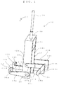
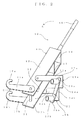
図1及び図2に示すように、開閉器操作工具蓄勢器10は、細長い一対の金属板等の板部材12a,12bと、これら板部材12a,12bを平行に間隔を置いて連結するスペーサ(間隔部材)14、15とで、図の縦方向に細長い箱形に形成された操作棒取付部材11を有する。操作棒取付部材11の上部に操作棒16が直立して取外し可能に取り付けられる。操作棒取付部材11の下部両側面には、一対の係止部材17a,17bと、操作工具30の一対の支持棒35a,35bが取付けられる一対の支持部材19a,19bとが、ピン21、22によって操作棒取付部材11に夫々回動可能に連結されている。
As shown in FIGS. 1 and 2, the switch operating
操作棒取付部材11を構成する板部材12a,12bとスペーサ14、15は、金属板で作られ、例えば溶接により、操作棒取付部材11を細長い箱形に一体的に形成することができる。或いは、板部材12a,12bとスペーサ14、15をヒンジ連結して折畳み可能に形成できると共に、ピン結合して分解可能に形成することもできる。
The plate members 12a and 12b and the
一対の係止部材17a,17bは、各々一方の端部において、操作棒取付部材11の側面を形成する板部材12a,12bにピン21により回動可能に取付けられている。他方の自由端部にフック18a,18bが設けられ、図3に示すように、操作工具30の連結金具33の係止ピン34a,34bに係合できるようになっている。
The pair of locking members 17a and 17b are rotatably attached to the plate members 12a and 12b forming the side surfaces of the operation
操作工具30の支持棒35a,35bを支持するための一対の支持部材19a,19bは、夫々略L字形を成しており、長い方の脚部23a,23bの一端部において操作棒取付部材11の板部材12a,12bにピン22により回動可能に取付けられ、他端部すなわち短い脚部24a,24bの側縁には、両者を連結する連結板25が横方向に延びている。連結板25の両端部は、支持部材19a,19bの外側に突出して張出部26a,26bを夫々形成し、これら外側に突出する張出部26a,26b上に、操作工具30を取付けるための筒状に形成された係合部材27a,27bが夫々取付けられている。尚、これら一対の支持部材19a,19bは、上記一対の係止部材17a,17bの上方において反対方向に延出するように操作棒取付部材11の両側面の板部材12a,12bに一端部が回動可能に取付けられている。
The pair of support members 19a and 19b for supporting the support rods 35a and 35b of the
円筒状の係合部材27a,27bは、連結板25の両側の張出部26a,26bの上に、例えば溶接して夫々固着することができる。或いは、各係合部材27a,27bの底面に耳部やブラケット部分を設けて、ピンで連結板25に回動可能に支持することも可能である。更に、球状自在継ぎ手(ボールジョイント)等によって傾動自在に支持することもできる。これら円筒状の係合部材27a,27bに、後述の操作工具30の支持棒35a,35bの端部35A,35Bが夫々嵌め込まれることにより、この蓄勢器10が操作工具30に取り付けられる。なお、係合部材27a,27bは、円筒形のほか角形その他の形状に形成してもよい。
Cylindrical engaging members 27a and 27b can be fixed to the projecting portions 26a and 26b on both sides of the connecting
上記の一対の係止部材17a,17b及び支持部材19a,19bを回動可能に取り付ける手段としては、ピン21、22のほか、頭付ねじやボルト等を使用することもできる。
As means for rotatably mounting the pair of locking members 17a and 17b and the supporting members 19a and 19b, head screws or bolts can be used in addition to the
操作工具30のばね部材32を蓄勢するために回動操作される操作棒16は、中実のロッド部材または中空のパイプ部材等によって1本のレバーとして作ることができるし、或いは複数本のロッド部材またはパイプ部材等を1本の部材として連結して作ることができる。
The operating
このように蓄勢器本体としての操作棒取付部材11、操作棒16、一対の係止部材17a,17b及び支持部材19a,19b、並びにピン21、22から構成される開閉器操作工具蓄勢器10は、収納箱を何等必要としていないので、重い収納箱を省略することができると共に、必要に応じて操作棒固定部材11を折畳み、或いは分解可能に形成することもでき、開閉器操作工具蓄勢器10を布袋やプラスチックの箱等に収納して容易に持ち運ぶことができる。しかも、この開閉器操作工具蓄勢器10は、モールドジスコンのような開閉器の操作工具30の連結金具34を介して、ばね部材32を簡単且つ容易に蓄勢することができる。また、ばね部材32を連続して蓄勢することも可能である。いずれにしても、操作に必要な力は少なくて済み、作業性と操作性が大幅に改善される。
As described above, the switch operating tool energy storage device including the operation
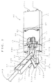
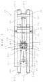
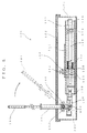
図3は、上記のように構成された開閉器操作工具蓄勢器を用いて、モールドジスコン等の開閉器の操作工具にばね力を蓄勢するときの使用状態を示し、図4は、操作工具の一例を概略的に示す平面図である。 FIG. 3 shows a use state when spring force is stored in an operating tool of a switch such as a mold disconter using the switch operating tool storage device configured as described above. It is a top view which shows an example of an operation tool roughly.
操作工具30は、工具本体31と、スライダとしての固定カバー42とを有し、フレームとしての工具本体31に2本の支持棒35a,35bが略平行に配設されており、これら2本の支持棒35a,35bの間の中心線上に配置された連結金具33と、中心線に沿って延びるように設けられた作動軸38と、作動軸38を取り囲んで巻回されたコイルスプリングのようなばね部材32とを有していて、支持棒35a,35bの端部35A,35Bが、開閉器操作工具蓄勢器10の円筒状の係合部材27a,27b内に嵌め込まれる。これにより、開閉器操作工具蓄勢器10が操作工具30に取付け支持される。
The
図示の操作工具30においては、支持棒35a,35bが、中空部材であるパイプや中実のロッドのような軸部材等を用いて形成されている。これによって、操作工具30の取付けに際しては、例えば、長ボルトのような頭部付きの取付ボルトを、操作工具30の中空のパイプ等の支持棒35a,35bの一方の端から差し込んで、他方の端から取付ボルトの先端部を突出させ、開閉器の支柱にねじ着して操作工具30を開閉器に取付けることができるようになっている。勿論、中空のパイプの代わりに、中実のロッドや軸または棒部材等を使用して支持棒を形成して用いることも可能であり、この場合には、適宜の連結部材又は継ぎ手を用いて支持棒を開閉器の支柱に取付けることができる。
In the illustrated
操作工具30の連結金具33は、両側に横方向に突出する連結用の係止ピン34a,34bが設けられており、且つ連結金具33の一端に蓄力スプリングとしてのばね部材32を押圧して圧縮するための作動軸38が連結されている。このような作動軸38は、中実のロッドや軸部材または棒部材等を用いて形成されるのが好適であるが、パイプのような中空部材を使用して形成することもできる。
The connection fitting 33 of the
更に、連結金具33は、先端部がフックのような鉤形に形成され、開閉器の開閉蓋の連結用ピンに係合して連結できるように構成される。また、作動軸38は、連結金具33に隣接して、合成ゴムまたは軟質のプラスチック材料等のような衝撃を吸収して緩和できる緩衝部材36を備えると共に、固定カバー42を固定するための固定部材37を貫通して延び、且つコイル状に巻回されたばね部材32の中心線に沿って延びて、他端が押圧部材39に連結されている。従って、ばね部材32は、コイルスプリングのように作動軸38の周りに巻回されて一端が固定部材37に当接され、他端は押圧部材39に当接されている。
Furthermore, the connection fitting 33 is formed in a hook-like shape like a hook, and is configured to engage and connect to a connection pin of an opening / closing lid of a switch. Further, the operating shaft 38 is provided with a buffer member 36 that can absorb and relieve an impact such as a synthetic rubber or a soft plastic material adjacent to the coupling metal 33 and a fixing member for fixing the fixing
押圧部材39は、両端部が支持棒35a,35bに嵌め込まれ、支持棒35a,35bに沿って滑動可能で、連結金具33を矢印Cの方向に係止部材17によって引っ張る時に、ばね部材32を圧縮してばね力を蓄勢するようにばね部材32の一方の端部が連結または当接されている。また、押圧部材39の外端部には、開閉器の差込みを行う場合に、開閉器の開閉蓋に連結できるように適宜の連結機構が設けられている。
Both ends of the pressing member 39 are fitted into the support rods 35a and 35b, and can slide along the support rods 35a and 35b. When the connecting member 33 is pulled by the locking
従って、連結金具33は、図4の実線で示される位置から、係止部材17a,17bによって引っ張られる鎖線で示される位置にまで移動可能である。この場合の移動距離が、ばね部材32が押圧されて圧縮される距離、すなわちばね圧縮量であって、ばね蓄勢力に比例するものである。 Therefore, the connection fitting 33 can move from the position shown by the solid line in FIG. 4 to the position shown by the chain line pulled by the locking members 17a and 17b. The moving distance in this case is the distance that the spring member 32 is pressed and compressed, that is, the amount of spring compression, and is proportional to the spring energy.
工具本体31上を滑動可能に設けられた固定カバー42の上には、ロックピン41を有したロック機構40と、固定カバー42を滑動操作するための取手46とが設けられている。尚、取手46は、固定カバー42の上面側だけでなく下面側、すなわち反対側の裏面側にも同じように設けることができ、これによって固定カバー42の移動及び固定操作を容易に行うことができると共に、操作工具30の保持を行なう時にも利用できて便宜であり、操作工具30を確実に保持することができる。
A
ロック機構40は、頭部付のロックピン41と、凸形のブラケット43と、ブラケット43の凸部に枢着されたロックピン抜け止めカバー44を有しており、ロックピン42の先端部が、作動軸38のロック位置に対応した位置に設けられた孔50に入ってロックされるように形成されている。また、ロックピン42は、固定部材37を貫通して下方に延びており、上下方向に動くことができるように設けられていて、作動軸38の孔50がロックピン42と一致する位置に来た時に、ロックピン42の先端部が作動軸38の孔50内に入って作動軸38に錠止可能、すなわちロック可能に係合されるようになっている。
The
従って、作動軸38をロックしているロック位置にあるロックピン42を上方に引き上げる時に、ロックピン42の先端部が作動軸38の孔50から外れて作動軸38が自由になるので、押圧された圧縮状態にあるばね部材32の蓄勢されたばね力が解放され、このばね力によって連結金具33が工具本体31の内側に向かって作動軸38と一緒に移動されるようになる。これによって、ばね部材32の蓄勢されたばね力を利用してモールドジスコンの可動モールド部を引抜き、或いは差し込みすることができて、開閉器の開閉が行われるようになる。
Therefore, when the
また、ロック機構40のロックピン41の抜け出るのを防止するために、ロックピン抜け止めカバー44が、ブラケット43の凸部にピン止めによって回動可能に枢着されている。更に、ロックピン抜け止めカバー44は、両側に作動ピン45a,45bが左右の方向に突き出るように設けられ、ロックピン抜け止めカバー44を回動して操作することができるようになっている。
In addition, in order to prevent the lock pin 41 of the
従って、ロック機構40をロック状態に維持する時には、作動ピン45a,45bを持ってロックピン抜け止めカバー44を回動してロックピン41の頭部の上に位置させることによって、ロック用の孔50に先端部が入っているロックピン41の抜け出るのを防止してロックピン41の上方への持ち上がりを防止することができるので、ロックピン41が作動軸38のロック用の孔50から外れて飛び出るのを阻止することができる。
Therefore, when the
更に、ロック機構40を解除可能にするためには、作動ピン45a,45bを操作してロックピン抜け止めカバー44をロックピン41の上から外すように前方または後方に回動すれば、ロックピン41の上方への持ち上がりが可能となってロックピン41の先端部が作動軸38の孔50から引き抜くことができるようになり、ロック機構40がロック解除待機状態に置かれるようになるので、ロックピン41を適宜の工具を用いて上方に持ち上げれば、ロック機構40が解除される。
Furthermore, in order to make the
また、操作工具30は、例えば連結金具33が設けられている端部側、すなわち図4の操作工具30の左側、が「切」側で、反対側の端部側、すなわち図4に示される右側、が「入」側であり、開閉器の開閉(切、入)を行う場合に、対応する側の端部を開閉器に対して差し込み、取付ボルトや連結部材等のような適宜の取付手段によって取付けられる。
Further, the
上記したように、開閉器操作工具蓄勢器10を操作工具30に対して取付けてセットし、連結金具33の係止ピン34a,34bに、開閉器操作工具蓄勢器10の係止部材17a,17bのフック18a,18bを係合させて操作棒16を図1乃至図3の矢印Aで示す方向に引っ張り、連結金具33を矢印Cの方向に引っ張ることによって、ばね部材32を圧縮してばね力を蓄勢し、作動軸38のロック用の孔50にロックピン41の先端部が落ちこんで係止することにより、ばね部材32を蓄勢状態に保持することができる。
As described above, the switch
従って、モールドジスコンの可動モールド部を引き抜く場合には、ばね部材32のばね力が蓄勢された操作工具30をモールドジスコンの可動モールド部の引き抜き側である「切」の位置に装着してロック機構40を解除すれば、ばね部材32の蓄勢力を利用してモールドジスコンの可動モールド部を引き抜くことができ、しかも円滑に連続して作業することができる。
Therefore, when pulling out the movable mold portion of the mold disc, the operating
以下、開閉器操作工具蓄勢器10を用いた操作工具の蓄勢作業の手順を説明する。
Hereinafter, the procedure of the operation tool storing operation using the switch operating
先ず、開閉器操作工具蓄勢器10を操作工具30にセットするため、係合部材27a,27bを操作工具30の支持棒35a,35bの端部35A,35Bに嵌めて装着する。
First, in order to set the switch
次に、係止部材17a,17bのフック18a,18bを連結金具33の係止ピン34a,34bに引っ掛ける。 Next, the hooks 18 a and 18 b of the locking members 17 a and 17 b are hooked on the locking pins 34 a and 34 b of the connection fitting 33.
続いて、操作棒固定部材11に操作棒16を差し入れて操作棒16を矢印Aの方向(図3の時計方向)に回動させる。この回動は、ロック機構40のロックピン41が作動軸38のロック用の孔50に落ち込んで係合するまで続けられる。このロックピン41によって作動軸38がロックされた時、ばね部材32の蓄勢が完了する。
Subsequently, the operating
そこで、開閉器操作工具蓄勢器10を操作工具30から取外せば、全ての蓄勢作業が完了する。
Then, if the switch
上記のように、開閉器操作工具蓄勢器10が装着された操作工具30において、操作工具30の支持棒35a,35bの端部35A,35Bが嵌め込まれた円筒状の係合部材27a,27bの底部を支点として、操作棒取付部材11が回動される。すなわち、円筒状の係合部材27a,27bと一体の支持部材19a,19bが固定された状態で、操作棒取付部材11はピン22を中心として矢印Aの方向(図3)に回動される。これにより、係止部材17a,17bが矢印Bの方向に引っ張られるので、フック18a,18bが係合した連結金具33の係止ピン34a,34bを介して、連結金具33と一体の作動軸38が矢印Cの方向に引っ張られ、押圧部材39によってばね部材32が圧縮されて、ばね力が蓄勢される。
As described above, in the operating
連結金具33の引っ張りによってばね部材32が圧縮され、必要なばね力が蓄勢された場合に、所定位置にセットされた固定カバー42上のロック機構40のロックピン41が作動軸38の孔50に嵌まってロックするまで、操作棒16を手前(矢印A方向)に引っ張る。従って、ロック機構40のロックピン41が下がれば、連結金具33を介した作動軸38によるばね部材32の蓄勢が完了するので、ばね部材32が十分に蓄勢されてロック機構40がロックされた状態に保持するようになり、これによってばね部材32が圧縮された蓄勢状態に維持される。このとき、ばね部材32は、連結金具33の図4の実線の位置から左方の鎖線の位置にまで移動された距離に等しい長さだけ圧縮される。
When the spring member 32 is compressed by pulling the connecting fitting 33 and a necessary spring force is accumulated, the lock pin 41 of the
このようにして、連結金具33の移動によって、ばね部材32が圧縮されてばね力が蓄勢された操作工具30から開閉器操作工具蓄勢器10を取外せば、蓄勢作業が完了する。
Thus, if the switch
これにより、モールドジスコン等の開閉器において、連結金具33と作動軸38を介してばね部材32が圧縮されて蓄勢されたばね力を利用して、モールドジスコンのような開閉器の可動モールド部の引抜き或いは嵌め込みを行うことができる。 As a result, in a switch such as a mold discon, a movable mold of a switch such as a mold disconter is utilized by using the spring force that is stored and compressed by the spring member 32 via the connecting fitting 33 and the operating shaft 38. The part can be pulled out or fitted.
従って、上述したように構成された開閉器操作工具蓄勢器10によって、モールドジスコン等のような開閉器における操作工具30のための収納箱が不要となるので、重量を大幅に軽減することができ、持ち運びが容易になる。
Accordingly, the switch
従来の操作工具においては、重量が約6.2kgもある蓋付きの収納箱を有する操作工具全体の重量が約14.5kg程と相当に重いものであったが、上記開閉器操作工具蓄勢器10の使用においては、このような重い収納箱が不要となるので、操作工具全体の重量が約8.8kg程度となり、約40%程の重量の軽減を計ることができるようになる。
In the conventional operation tool, the weight of the entire operation tool having a storage box with a lid of about 6.2 kg is as heavy as about 14.5 kg. When the
しかも、モールドジスコン等の開閉器の操作工具30に対して開閉器操作工具蓄勢器10を所定位置にセットして操作棒16を操作することによって、操作工具30の支持棒35a,35bの一部を使って支点として用い、てこの原理を利用して係止部材17a,17bを介してばね部材32を圧縮して所要のばね力を蓄勢することができる。そして、ばね力が蓄勢された操作工具30をモールドジスコンの可動モールド部の引抜く側である「切」の位置に装着し、ロック機構40のロックピン41を解除すれば、操作工具30に蓄勢されたばね力を利用してモールドジスコンの可動モールド部を引抜くことができ、作業性及び操作性が大幅に改善される。
In addition, by setting the switch
また、モールドジスコンの可動モールド部を嵌め込む場合には、開閉器操作工具蓄勢器10によってばね力が蓄勢された操作工具30をモールドジスコンの可動モールド部の、上記とは逆の嵌め込み側である「入」の位置に装着して、ロック機構40を解除すれば、ばね部材32の蓄勢力を利用してモールドジスコンの可動モールド部を嵌め込むことができると共に、円滑に連続して作業することができる。
Further, when the movable mold part of the mold disc is fitted, the
以上、図示の実施例について説明したが、本発明はこれに限定されず、種々の変更及び変形が可能である。 Although the illustrated embodiment has been described above, the present invention is not limited to this, and various changes and modifications can be made.
10…開閉器操作工具蓄勢器、11…操作棒取付部材、12a,12b…板部材、14,15…スペーサ、16…操作棒、17a,17b…係止部材、18a,18b…フック、19a,19b…支持部材、21,22…ピン、23a,23b,24a,24b…脚部、25…連結板、26a,26b…張出部、27a,27b…係合部材、30…操作工具、31…工具本体、32…ばね部材、33…連結金具、34a,34b…係止ピン、35a,35b…支持棒、35A,35B…端部、36…緩衝部材、37…固定部材、38…作動軸、39…押圧部材、40…ロック機構、41…ロックピン、42…固定カバー、43…ブラケット、44…ロックピン抜け止めカバー、45a,45b…作動ピン、46…取手、50…孔。
DESCRIPTION OF
Claims (5)
操作棒を取付けて回動操作される操作棒取付部材と、
該操作棒取付部材に連結した各々の一端部を支点として該操作棒取付部材の回動する方向に回動可能に取り付けられ、各々の他端部が前記連結金具に係合される一対の係止部材と、
前記係止部材と反対側で前記操作棒取付部材に連結した各々の一端部を支点として回動可能に取り付けられ、各々の他端部に前記開閉器操作工具の一対の支持棒に係合する係合部材を設けた一対の支持部材と
を備えたことを特徴とする開閉器操作工具蓄勢器。 An operating shaft that moves in a direction in which the spring member is compressed, a pair of support rods that are disposed substantially parallel to each other across the operating shaft, a lock mechanism that locks the operating shaft at a predetermined position, and An accumulator for accumulating spring force in a switch operating tool having a connection fitting coupled to one end,
An operation rod mounting member that is rotated by attaching the operation rod;
A pair of engagements, each of which is pivotably mounted in the direction of rotation of the operation rod mounting member with each one end connected to the operation rod mounting member as a fulcrum, and each of the other ends is engaged with the connection fitting. A stop member;
Each end connected to the operation rod mounting member on the side opposite to the locking member is pivotally mounted with a fulcrum as a fulcrum, and the other end engages with a pair of support rods of the switch operating tool. A switch operating tool energy storage comprising a pair of support members provided with engaging members.
前記係合部材は、前記一対の支持棒の先端部が嵌め込まれる筒状に形成されていることを特徴とする開閉器操作工具蓄勢器。 The switch operating tool energy storage device according to claim 1,
The switch operating tool accumulator according to claim 1, wherein the engaging member is formed in a cylindrical shape into which front ends of the pair of support rods are fitted.
前記支持部材は略L字状に形成され、L字形の一方の端部にて前記操作棒取付部材に回動可能に取り付けられ、他方の端部の間には両者を連結すると共に両端が外側に突出した連結板を有し、
該連結板の両端部に前記係合部材が設けられていることを特徴とする開閉器操作工具蓄勢器。 The switch operating tool energy storage device according to claim 1,
The support member is formed in a substantially L shape, and is rotatably attached to the operation rod mounting member at one end of the L shape, and both ends are connected to each other between the other ends. Has a connecting plate protruding to
A switch operating tool accumulator characterized in that the engaging members are provided at both ends of the connecting plate.
前記一対の係止部材は、各々の他端部に前記開閉器操作工具の連結金具に係合するフックを有することを特徴とする開閉器操作工具蓄勢器。 The switch operating tool energy storage device according to claim 1,
The pair of locking members has a hook that engages with a connection fitting of the switch operating tool at the other end of each of the pair of locking members.
前記操作棒取付部材は、前記操作棒を受け入れる一対の平行な細長い板部材と間隔部材とで箱形に形成されていることを特徴とする開閉器操作工具蓄勢器。 The switch operating tool energy storage device according to claim 1,
The switch operating tool energy storage device, wherein the operating rod mounting member is formed in a box shape by a pair of parallel elongated plate members and spacing members that receive the operating rod.
Priority Applications (1)
| Application Number | Priority Date | Filing Date | Title |
|---|---|---|---|
| JP2006118716A JP2007294167A (en) | 2006-04-24 | 2006-04-24 | Spring energy accumulating apparatus for switch operating tool |
Applications Claiming Priority (1)
| Application Number | Priority Date | Filing Date | Title |
|---|---|---|---|
| JP2006118716A JP2007294167A (en) | 2006-04-24 | 2006-04-24 | Spring energy accumulating apparatus for switch operating tool |
Publications (1)
| Publication Number | Publication Date |
|---|---|
| JP2007294167A true JP2007294167A (en) | 2007-11-08 |
Family
ID=38764586
Family Applications (1)
| Application Number | Title | Priority Date | Filing Date |
|---|---|---|---|
| JP2006118716A Pending JP2007294167A (en) | 2006-04-24 | 2006-04-24 | Spring energy accumulating apparatus for switch operating tool |
Country Status (1)
| Country | Link |
|---|---|
| JP (1) | JP2007294167A (en) |
Cited By (1)
| Publication number | Priority date | Publication date | Assignee | Title |
|---|---|---|---|---|
| JP2019537219A (en) * | 2016-11-17 | 2019-12-19 | アジェ−エレクトロ エスアーエスHager−Electro Sas | Circuit breaker with reset lever by telescopic pumping |
-
2006
- 2006-04-24 JP JP2006118716A patent/JP2007294167A/en active Pending
Cited By (1)
| Publication number | Priority date | Publication date | Assignee | Title |
|---|---|---|---|---|
| JP2019537219A (en) * | 2016-11-17 | 2019-12-19 | アジェ−エレクトロ エスアーエスHager−Electro Sas | Circuit breaker with reset lever by telescopic pumping |
Similar Documents
| Publication | Publication Date | Title |
|---|---|---|
| CN202019551U (en) | Retractable handle of mower | |
| WO2017020820A1 (en) | Energy storage operating mechanism for circuit breaker | |
| EP3116819A1 (en) | Lifting hook, safety latch of lifting hook and locking and releasing device of safety latch | |
| WO2010102466A1 (en) | Rod fixing device | |
| JP2017086727A (en) | Fire hydrant device | |
| US11235878B2 (en) | Storage compartment and latch therefor | |
| CN100589298C (en) | pull-out circuit breaker | |
| JP2009082955A (en) | Compression packing equipment | |
| KR20160029943A (en) | Apparatus for locking wing door of truck | |
| KR101815100B1 (en) | Apparatus for withdrawable circuit breaker | |
| JP2012180676A (en) | Lock handle device for door | |
| CN217262145U (en) | Container door and container | |
| CN105781265B (en) | A kind of indoor electromagnetic lock | |
| KR200474919Y1 (en) | Automatic loading and unloading carts carrying bricks | |
| CN102500456B (en) | a shredder | |
| KR101441248B1 (en) | A opening and closing structure of sliding cover for loading board | |
| CN109573375B (en) | Container and locking device thereof | |
| JP2001019108A (en) | Opening / closing door lashing device for garbage storage box detachably mounted on transport vehicle | |
| CN222114923U (en) | Claw type valve spanner | |
| KR101848587B1 (en) | Drum drawing out and storage device of cabinet | |
| JP6598608B2 (en) | Fire hydrant equipment | |
| JP6255580B2 (en) | Handle device for electrical and electronic equipment storage box | |
| CN112542347B (en) | Switching-on interlocking mechanism of circuit breaker | |
| CN221319189U (en) | Fork truck folding handle | |
| JP2000270419A (en) | Vertical self-standing board |