JP2012180676A - Lock handle device for door - Google Patents

Lock handle device for door Download PDF

Info

Publication number
JP2012180676A
JP2012180676A JP2011043944A JP2011043944A JP2012180676A JP 2012180676 A JP2012180676 A JP 2012180676A JP 2011043944 A JP2011043944 A JP 2011043944A JP 2011043944 A JP2011043944 A JP 2011043944A JP 2012180676 A JP2012180676 A JP 2012180676A
Authority
JP
Japan
Prior art keywords
handle
lever
lock
door
fixed
Prior art date
Legal status (The legal status is an assumption and is not a legal conclusion. Google has not performed a legal analysis and makes no representation as to the accuracy of the status listed.)
Granted
Application number
JP2011043944A
Other languages
Japanese (ja)
Other versions
JP5291738B2 (en
Inventor
Shiro Segawa
志朗 瀬川
Current Assignee (The listed assignees may be inaccurate. Google has not performed a legal analysis and makes no representation or warranty as to the accuracy of the list.)
Takigen Manufacturing Co Ltd
Original Assignee
Takigen Manufacturing Co Ltd
Priority date (The priority date is an assumption and is not a legal conclusion. Google has not performed a legal analysis and makes no representation as to the accuracy of the date listed.)
Filing date
Publication date
Application filed by Takigen Manufacturing Co Ltd filed Critical Takigen Manufacturing Co Ltd
Priority to JP2011043944A priority Critical patent/JP5291738B2/en
Publication of JP2012180676A publication Critical patent/JP2012180676A/en
Application granted granted Critical
Publication of JP5291738B2 publication Critical patent/JP5291738B2/en
Active legal-status Critical Current
Anticipated expiration legal-status Critical

Links

Images

Landscapes

  • Lock And Its Accessories (AREA)

Abstract

PROBLEM TO BE SOLVED: To provide a lock handle device for a door, capable of an electric unlocking operation by a solenoid and capable of unlocking by a lock operation when unlocking is impossible due to a fault.SOLUTION: A locking unit 27 includes a latch lever 28, a lock unit 29, and a solenoid unit 30. The latch lever 28 is engaged with an engaging part 26 of a lever handle 5 at a lock position at an engaging position, releases it at a non-engaging position, and is rotationally urged to the engaging position at normal time. The lock unit 29 is capable of rotating the latch lever 28 to the non-engaging position by a key operation. The latch lever 28 is rotated to the non-engaging position tentatively by being pushed by the engaging part 26 of the lever handle 5 brought down and turned to the lock position, is then rotated and restored to the engaging position, and automatically locks the lever handle 5. When the solenoid unit 30 is energized, the latch lever 28 releases the lever handle 5, and the opening operation of a door D is made possible.

Description

この発明は、電気機器格納用キャビネット等において、閉鎖状態の扉をキャビネット本体等の固定枠体に対して締付け錠止するクランプ式の扉用ロックハンドル装置に関する。   The present invention relates to a clamp-type door lock handle device for fastening and locking a closed door to a fixed frame body such as a cabinet body in an electrical equipment storage cabinet or the like.

分電盤や配電盤等の電気機器収納用キャビネットの扉用ロックハンドル装置として、例えば、特許文献1に記載されダブルクランプ式の扉用ロックハンドル装置が知られている。このロックハンドル装置は、固定枠体側に相互間に距離を置いて設けられる第1ストライク及び第2ストライクと;扉を閉鎖したとき第1ストライク及び第2ストライクと対面する位置において扉に固着される本体ケースと;前記本体ケースに収容され、扉前面と平行な第1固定枢軸によって本体ケースに枢着され、第1固定枢軸よりも先端側の部位に駆動アームを設けたレバーハンドルと;第1固定枢軸と平行な第1可動軸によって前端部を前記駆動アームの先端部に枢着された連結リンクと;第1固定枢軸と平行であって第1固定枢軸よりも斜め後方に配置した第2固定枢軸によって基端部を本体ケースに枢着され、本体ケースの背面側に突出した先端フック部が第1ストライクに係脱する第1クランプ体と;第1固定枢軸と平行であって第1固定枢軸よりも斜め後方に配置した第3固定枢軸によって基端部を本体ケースに枢着され、本体ケースの背面側に突出した先端フック部が第2ストライクに係脱する第2クランプ体とからなり、扉前面に対して直角であって第1固定枢軸を通る動作基準線に関して第2固定枢軸と第3固定枢軸を対称位置に配置し、第1固定枢軸と平行であって前記動作基準線に沿って移動する第2可動枢軸によって第1クランプ体の受動肩部と第2クランプ体の受動肩部を前記連結リンクの後端部に連結し、第1クランプ体の先端フック部が第1ストライクに係合し、第2クランプ体の先端フック部が第2ストライクに係合した扉施錠状態において、第1可動枢軸が前記動作基準線を第2固定枢軸側に越えた位置に来る一方、第1クランプ体の先端フック部が第1ストライクから離脱し、第2クランプ体の先端フック部が第2ストライクから離脱した扉解錠状態において、第1可動枢軸が前記動作基準線を第3固定枢軸側に越えた位置に来るようにしたものである。この装置では、第2可動枢軸を動作基準線に沿って移動させるために、その両端部を本体ケースに形成されたガイド用スロットに挿入する構成である。また、第1クランプ体の受動肩部と第2クランプ体の受動肩部にはそれぞれ連動用スロットが形成され、これらの連動用スロットに第2可動枢軸を挿通させて両クランプ体を連結リンクの後端部に連結する構成である。   As a door lock handle device for a cabinet for storing electrical equipment such as a distribution board or a distribution board, for example, a double clamp type door lock handle device described in Patent Document 1 is known. The lock handle device is fixed to the door at a position facing the first strike and the second strike when the door is closed; a first strike and a second strike provided at a distance from each other on the fixed frame body side; A main body case; a lever handle housed in the main body case, pivotally attached to the main body case by a first fixed pivot parallel to the front surface of the door, and provided with a drive arm at a position on the tip side of the first fixed pivot; A connecting link whose front end is pivotally attached to the tip of the drive arm by a first movable shaft parallel to the fixed pivot; a second link disposed parallel to the first fixed pivot and obliquely rearward of the first fixed pivot A first clamp body having a base end portion pivotally attached to the main body case by a fixed pivot, and a distal end hook portion protruding to the back side of the main body case engaging and disengaging with the first strike; and parallel to the first fixed pivot A second clamp body in which a base end portion is pivotally attached to the main body case by a third fixed pivot disposed obliquely rearward from the first fixed pivot, and a distal end hook portion protruding to the back side of the main body case is engaged with and disengaged from the second strike The second fixed pivot and the third fixed pivot are arranged symmetrically with respect to an operation reference line perpendicular to the door front surface and passing through the first fixed pivot, and the movement is parallel to the first fixed pivot The passive shoulder of the first clamp body and the passive shoulder of the second clamp body are connected to the rear end of the connection link by the second movable pivot that moves along the reference line, and the front hook portion of the first clamp body is In the door locked state in which the first strike is engaged and the tip hook portion of the second clamp body is engaged with the second strike, the first movable pivot comes to a position beyond the operation reference line toward the second fixed pivot. On the other hand, the front end of the first clamp body In a door unlocked state in which the hook part is detached from the first strike and the tip hook part of the second clamp body is detached from the second strike, the position where the first movable pivot exceeds the operation reference line toward the third fixed pivot It is something that comes to come. In this apparatus, in order to move the second movable pivot along the operation reference line, both end portions thereof are inserted into guide slots formed in the main body case. In addition, an interlocking slot is formed in each of the passive shoulder of the first clamp body and the passive shoulder of the second clamp body, and the second movable pivot is inserted into these interlocking slots so that both clamp bodies are connected to the link link. It is the structure connected with a rear-end part.

特開2006−63673号公報JP 2006-63673 A

この出願に係る発明は、ソレノイドユニットによる電気的な解錠操作を可能とし、かつ電気的障害による解錠不能時には、キーによる錠前操作で解錠を可能とする扉用ロックハンドル装置を提供することを目的としている。   The invention according to this application provides a door lock handle device that can be electrically unlocked by a solenoid unit and can be unlocked by a key lock operation when unlocking is impossible due to an electrical failure. It is an object.

以下、添付図面の符号を参照して説明するが、本発明はこれに限定されるものではない。
上記課題を解決するための、この出願に係る発明の扉用ロックハンドル装置は、固定枠体側に設けられるストライク1,2と、扉Dを閉鎖したときストライク1,2の前方に対面する位置において当該扉Dに固着されるハンドルベース3と、扉Dの前面と平行な第1固定枢軸4によって基端側においてハンドルベース3に起伏自在に枢着されるレバーハンドル5と、基端部が第1固定枢軸4と平行な第2固定枢軸7によってハンドルベース3に枢着されるクランプ体8,21と、倒伏したレバーハンドル5に対面する位置においてこれを拘束するためにハンドルベース3に設けられる施錠ユニット27とを具備する。レバーハンドル5は、倒伏したロック位置と起立した非ロック位置との間を回転自在で、ロック位置において基端から先端へ上下方向に延び、第1固定枢軸4よりも先端側の部位においてロック位置における後方へ延出する駆動アーム6を有する。クランプ体8,21は、基端部9,22と、基端部からハンドルベース3の背面側に突出するフック部10,23と、基端部9,22からフック部10,23と反対方向へ延出する受動肩部11,24とを有する。基端部9、22は、第2固定枢軸7によってハンドルベースに枢着される。受動肩部11,24は、連結リンク14を介してレバーハンドル5に連結され、レバーハンドル5に連動してロック位置と非ロック位置との間を正逆回転する。ロック位置においてフック部10,23がストライク1,2に係合し、非ロック位置においてフック部10,23がストライク1,2から離脱する。さらに、レバーハンドル5は、ロック位置において施錠ユニット27に拘束される係合部26を具備する。施錠ユニット27は、ラッチレバー28と、錠前ユニット29と、ソレノイドユニット30とを具備する。ラッチレバー28は、第1固定枢軸4と平行なラッチ軸33によりハンドルベース3に枢支され、ロック位置にあるレバーハンドル5の係合部26に係合する係合位置と、それから離脱する非係合位置との間を正逆回転自在であり、常時は係合位置に回転付勢される。錠前ユニット29は、ハンドルベース3に固着され、キー操作によりラッチレバー28を非係合位置へ回転操作可能である。ラッチレバー28は、ロック位置へ倒伏回動するレバーハンドル5の係合部26に押されていったん非係合位置へ回転した後、係合位置へ回転復元する。ソレノイドユニット30は、ハンドルベース3に固着され、通電時にラッチレバー28を非係合位置に保持し、常時はラッチレバー28を解放する。
Hereinafter, the present invention will be described with reference to the accompanying drawings, but the present invention is not limited thereto.
In order to solve the above problems, the door lock handle device of the invention according to this application is provided with strikes 1 and 2 provided on the fixed frame side, and at a position facing the front of the strikes 1 and 2 when the door D is closed. A handle base 3 fixed to the door D, a lever handle 5 pivotably mounted on the handle base 3 on the base end side by a first fixed pivot 4 parallel to the front surface of the door D, and a base end portion of the handle base 3 A clamp body 8, 21 pivotally attached to the handle base 3 by a second fixed pivot 7 parallel to the first fixed pivot 4, and a handle base 3 for restraining the clamp body 8, 21 at a position facing the fallen lever handle 5. And a locking unit 27. The lever handle 5 is rotatable between a lying locked position and a standing unlocked position, and extends vertically from the proximal end to the distal end at the locked position, and is locked at a position closer to the distal end than the first fixed pivot 4. And a drive arm 6 extending rearward. The clamp bodies 8 and 21 have base end portions 9 and 22, hook portions 10 and 23 projecting from the base end portion to the back side of the handle base 3, and directions from the base end portions 9 and 22 to the hook portions 10 and 23. Passive shoulders 11, 24 extending to The base end portions 9 and 22 are pivotally attached to the handle base by the second fixed pivot 7. The passive shoulder portions 11 and 24 are connected to the lever handle 5 via the connecting link 14 and rotate forward and backward between the locked position and the unlocked position in conjunction with the lever handle 5. The hook portions 10 and 23 engage with the strikes 1 and 2 at the locked position, and the hook portions 10 and 23 are detached from the strikes 1 and 2 at the unlocked position. Furthermore, the lever handle 5 includes an engaging portion 26 that is restrained by the locking unit 27 in the locked position. The locking unit 27 includes a latch lever 28, a lock unit 29, and a solenoid unit 30. The latch lever 28 is pivotally supported on the handle base 3 by a latch shaft 33 parallel to the first fixed pivot 4, and engages with the engagement portion 26 of the lever handle 5 in the locked position, and is detached from it. It can freely rotate forward and backward between the engagement positions and is normally urged to rotate to the engagement position. The lock unit 29 is fixed to the handle base 3, and the latch lever 28 can be rotated to a non-engagement position by a key operation. The latch lever 28 is pushed by the engaging portion 26 of the lever handle 5 that turns down to the lock position and once rotates to the non-engagement position, and then returns to the engagement position. The solenoid unit 30 is fixed to the handle base 3, holds the latch lever 28 in the disengaged position when energized, and normally releases the latch lever 28.

この出願に係る発明によれば、ソレノイドユニットによる電気的な解錠操作を可能とし、かつ電気的障害による解錠不能時には、キーによる錠前操作で解錠を可能とする扉用ロックハンドル装置を提供することができる。   According to the invention according to this application, there is provided a door lock handle device that can be electrically unlocked by a solenoid unit and can be unlocked by a lock operation using a key when unlocking is impossible due to an electrical failure. can do.

本発明に係る扉用ロックハンドル装置の非ロック状態の縦断面図である。It is a longitudinal cross-sectional view of the unlocking state of the lock handle apparatus for doors concerning this invention. 図1の扉用ロックハンドル装置の操作途上における縦断面図である。It is a longitudinal cross-sectional view in the middle of operation of the lock handle apparatus for doors of FIG. 図1の扉用ロックハンドル装置の錠止状態の縦断面図である。It is a longitudinal cross-sectional view of the lock state of the lock handle apparatus for doors of FIG. 図1の扉用ロックハンドル装置のソレノイドによる解錠状態の一部の縦断面図である。It is a longitudinal cross-sectional view of a part of the unlocking state by the solenoid of the lock handle device for doors of FIG. 図1の扉用ロックハンドル装置の錠前よる解錠状態の一部の縦断面図である。It is a partial longitudinal cross-sectional view of the unlocking state by the lock of the lock handle apparatus for doors of FIG. 図1の扉用ロックハンドル装置を扉の裏側から見た背面図である。It is the rear view which looked at the lock handle device for doors of Drawing 1 from the back side of the door. 図1の扉用ロックハンドル装置の平面図である。It is a top view of the lock handle apparatus for doors of FIG.

図面を参照してこの発明の実施の形態を説明する。
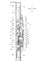
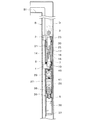
図1ないし図3は、本発明のロックハンドル装置を扉Dに取り付けた状態を示す縦断側面図であって、図1は非ロック状態、図2は操作途上状態、図3は錠止状態を示している。図において1は第1ストライク、2は第2ストライクであり、上下方向に所要間隔を置いて、キャビネット等の本体である固定枠体Bにおける開口部の周囲フランジ部B1に固着される。
Embodiments of the present invention will be described with reference to the drawings.
1 to 3 are longitudinal side views showing a state in which the lock handle device of the present invention is attached to the door D. FIG. 1 shows an unlocked state, FIG. 2 shows an operating state, and FIG. 3 shows a locked state. Show. In the figure, reference numeral 1 denotes a first strike and 2 denotes a second strike, which are fixed to a peripheral flange B1 of an opening in a fixed frame B which is a main body of a cabinet or the like with a predetermined interval in the vertical direction.

ロックハンドル装置のハンドルベース3は、閉扉時にストライク1,2に対向するように、扉Dの自由端部側の前面に配置され、扉Dの裏(後面)側からねじで扉Dに締め付け固着される。   The handle base 3 of the lock handle device is arranged on the front surface of the free end portion side of the door D so as to face the strikes 1 and 2 when the door is closed, and is fastened and fixed to the door D with a screw from the back (rear surface) side of the door D. Is done.

第1固定枢軸4は、扉Dの前面と平行で、両端においてハンドルベース3の左右側壁部に支持され、中間部がレバーハンドル5の上端(基端)部を水平方向に貫通している。レバーハンドル5は、第1固定枢軸4を中心に、ハンドルベース3に対して起立した非ロック位置(図1)と、倒伏したロック位置(図3)との間を、途上位置(図2)を経て回転自在で、ロック位置において、扉Dの前面に沿って上下方向に延びるように配置される。レバーハンドル5は、ロック位置において第1固定枢軸4よりも後方(扉の背面側)へ延出する駆動アーム6を上端側有すると共に、ロック位置においてハンドルベース3側へ突出する係合部26を下端側に有し、また中間部には、ランプ表示用開口44、スイッチ押圧用突起45、キー挿通用開口46を有する。係合部26は、ハンドルベース3側に設けられる施錠ユニット27の施錠操作により拘束される。   The first fixed pivot 4 is parallel to the front surface of the door D and is supported by the left and right side wall portions of the handle base 3 at both ends, and the intermediate portion penetrates the upper end (base end) portion of the lever handle 5 in the horizontal direction. The lever handle 5 has a halfway position (FIG. 2) between a non-locking position (FIG. 1) standing up with respect to the handle base 3 and a lying locked position (FIG. 3) around the first fixed pivot 4. And is arranged so as to extend in the vertical direction along the front surface of the door D at the lock position. The lever handle 5 has a drive arm 6 that extends rearward (back side of the door) from the first fixed pivot 4 in the locked position, and an engaging portion 26 that protrudes toward the handle base 3 in the locked position. The lamp display opening 44, the switch pressing projection 45, and the key insertion opening 46 are provided at the lower end side and in the middle part. The engaging portion 26 is restrained by a locking operation of a locking unit 27 provided on the handle base 3 side.

第2固定枢軸7は、第1固定枢軸4と平行で、第1固定枢軸の斜め下後方位置において、両端がハンドルベース3の左右側壁部に支持され、中間部が第1クランプ体8の基端部9を水平方向に貫通している。第1クランプ体8は、基端部9と、基端部9からハンドルベース3の背面側に突出するフック部10と、基端部からフック部10と反対方向へ延出する受動肩部11とを有する。また、基端部9からばね受け突起12が突出している。   The second fixed pivot 7 is parallel to the first fixed pivot 4, and both ends are supported by the left and right side wall portions of the handle base 3 at an obliquely lower rear position of the first fixed pivot, and the intermediate portion is the base of the first clamp body 8. The end 9 is penetrated in the horizontal direction. The first clamp body 8 includes a base end portion 9, a hook portion 10 protruding from the base end portion 9 to the back side of the handle base 3, and a passive shoulder portion 11 extending from the base end portion in a direction opposite to the hook portion 10. And have. A spring receiving protrusion 12 protrudes from the base end portion 9.

第1可動枢軸13は、第1固定枢軸4と平行で、両端においてレバーハンドル5における駆動アーム6の先端部に支持される。第1可動枢軸13の中間部は、第1連結リンク14の第1枢支点を貫通する。第1連結リンク14は、ほぼL字形の板状で、一端側に第1枢支点、中間に第2枢支点、他端側に第3枢支点を有し、また第1枢支点付近にばね受け突起15を有する。   The first movable pivot 13 is parallel to the first fixed pivot 4 and is supported at both ends by the tip of the drive arm 6 in the lever handle 5. The intermediate portion of the first movable pivot 13 passes through the first pivot point of the first connection link 14. The first connecting link 14 is substantially L-shaped, has a first pivot point at one end, a second pivot point in the middle, a third pivot point at the other end, and a spring near the first pivot point. A receiving projection 15 is provided.

第2可動枢軸16は、第1固定枢軸4と平行で、第1連結リンク14の第2枢支点と第2連結リンク17の一端部とを枢支する。第3可動枢軸18は、第1固定枢軸4と平行で、第1連結リンク14の第3枢支点と第1クランプ体8の受動肩部11とを枢支する。第1クランプ体8のばね受け突起12と第1連結リンク14のばね受け突起15との間(実質的には、第2固定枢軸9と第1可動枢軸13との間)には、反転ばね19が挿入される。   The second movable pivot 16 is parallel to the first fixed pivot 4 and pivotally supports the second pivot point of the first connection link 14 and one end of the second connection link 17. The third movable pivot 18 is parallel to the first fixed pivot 4 and pivotally supports the third pivot point of the first connection link 14 and the passive shoulder 11 of the first clamp body 8. A reversing spring is provided between the spring receiving protrusion 12 of the first clamp body 8 and the spring receiving protrusion 15 of the first connecting link 14 (substantially between the second fixed pivot 9 and the first movable pivot 13). 19 is inserted.

第3固定枢軸20は、第1固定枢軸4と平行で、第1固定枢軸の斜め上後方位置において、両端がハンドルベース3の左右側壁部に支持され、中間部が第2クランプ体21の基端部22を水平方向に貫通している。第2クランプ体21は、第1クランプ体8と同形で、それと上下反転した状態に設けられ、基端部22と、基端部22からハンドルベース3の背面側に突出するフック部23と、基端部からフック部23と反対方向へ延出する受動肩部24とを有する。第4可動枢軸25は、第1固定枢軸4と平行で、第2連結リンク17の他端部と第2クランプ体21の受動肩部24とを枢支する。   The third fixed pivot 20 is parallel to the first fixed pivot 4, and both ends are supported by the left and right side wall portions of the handle base 3 at the diagonally upper and rear positions of the first fixed pivot, and the middle portion is the base of the second clamp body 21. The end part 22 is penetrated in the horizontal direction. The second clamp body 21 has the same shape as the first clamp body 8 and is provided in a vertically inverted state. The base end portion 22, and the hook portion 23 that protrudes from the base end portion 22 to the back side of the handle base 3, It has a passive shoulder 24 that extends in the opposite direction from the hook 23 from the proximal end. The fourth movable pivot 25 is parallel to the first fixed pivot 4 and pivotally supports the other end of the second connection link 17 and the passive shoulder 24 of the second clamp body 21.

したがって、第1、第2クランプ体8,21は、レバーハンドル5の起伏回転に連動して、非ロック位置(図1)とロック位置(図3)との間を正逆回転し、ロック位置においてフック部10,23が、それぞれ第1、第2ストライク1,2に対して上方又は下方から背面に係合し、非ロック位置においてフック部10,23が第1、第2ストライク1,2から離脱する。   Accordingly, the first and second clamp bodies 8 and 21 rotate forward and backward between the unlocked position (FIG. 1) and the locked position (FIG. 3) in conjunction with the up-and-down rotation of the lever handle 5. The hook portions 10 and 23 are engaged with the first and second strikes 1 and 2 from the upper side or the lower side, respectively, and the hook portions 10 and 23 are engaged with the first and second strikes 1 and 2 in the unlocked position. Leave.

反転ばね19は、実質的に、一端側が第1可動枢軸13に係止され、他端側が第2固定枢軸7に係止されているので、非ロック位置にあるレバーハンドル5を起立状態(図1)に保持(図1において固定枢軸4を中心に反時計方向の回転力を付与)し、非ロック位置からロック位置への回転途上(図2)で圧死点を越え、ロック位置(図3)にあるレバーハンドル5を倒伏状態に保持(図3において軸4を中心に時計方向の回転力を付与)する。   The reversing spring 19 is substantially engaged at one end side with the first movable pivot 13 and at the other end with the second fixed pivot 7, so that the lever handle 5 in the unlocked position is raised (see FIG. 1) (applying a counterclockwise rotational force about the fixed pivot 4 in FIG. 1), the pressure dead center is exceeded during the rotation from the unlocked position to the locked position (FIG. 2), and the locked position (FIG. 3). ) Is held in a lying state (a clockwise rotational force is applied about the shaft 4 in FIG. 3).

ロックハンドル装置の本体は、図1に示すように、クランプ体8,21のフック部10,23がストライク1,2から離脱した非ロック位置において、第1可動枢軸(第1枢支点)13と第2可動枢軸(第2枢支点)16とを結ぶ直線L1が、第2可動枢軸(第2枢支点)16から扉前面に対して直角に延びる基準直線Lより下方にある一方、図3に示すように、クランプ体8,21のフック部10,23がストライク1,2に係合したロック位置において、直線L1が、基準直線Lを上方へ越えた位置に来るように各部が配置される。   As shown in FIG. 1, the main body of the lock handle device includes a first movable pivot (first pivot point) 13 and an unlocked position where the hook portions 10 and 23 of the clamp bodies 8 and 21 are detached from the strikes 1 and 2. While the straight line L1 connecting the second movable pivot (second pivot point) 16 is below the reference straight line L extending perpendicularly to the door front surface from the second movable pivot (second pivot point) 16, FIG. As shown, at the locked position where the hook portions 10 and 23 of the clamp bodies 8 and 21 are engaged with the strikes 1 and 2, the respective portions are arranged so that the straight line L1 comes to a position exceeding the reference straight line L. .

レバーハンドル5をロック位置に錠止するための施錠ユニット27は、レバーハンドル5の下端側に対応する位置においてハンドルベース3上に設けられる。施錠ユニット27は、ラッチレバー28と、錠前ユニット29と、ソレノイドユニット30と、リミットスイッチ42と、LEDランプ43とを具備する。   A locking unit 27 for locking the lever handle 5 in the locked position is provided on the handle base 3 at a position corresponding to the lower end side of the lever handle 5. The locking unit 27 includes a latch lever 28, a lock unit 29, a solenoid unit 30, a limit switch 42, and an LED lamp 43.

ハンドルベース3には、レバーハンドル5の係合部26に対応する位置に、ラッチ収納空間31が設けられ、また、開口46に対応する位置に、錠前収納空間32が設けられる。ラッチ収納空間31内には、第1固定枢軸4と平行なラッチ軸33によりラッチレバー28が枢支され、錠前収納空間32内には、錠前のシリンダケース34が固着される。   The handle base 3 is provided with a latch storage space 31 at a position corresponding to the engaging portion 26 of the lever handle 5, and a lock storage space 32 is provided at a position corresponding to the opening 46. A latch lever 28 is pivotally supported in the latch storage space 31 by a latch shaft 33 parallel to the first fixed pivot 4, and a lock cylinder case 34 is fixed in the lock storage space 32.

ラッチレバー28は、ラッチ軸33より前方へ延出するフック部40と、後方へ延出する操作部41とを具備し、ロック位置にあるレバーハンドル5の係合部26に係合する係合位置(図3)と、それから離脱する非係合位置(図1)との間を回動自在であり、常時はばね35で係合位置に回転付勢される。したがって、ラッチレバー28は、ロック位置へ倒伏回動するレバーハンドル5の係合部26にフック部40が押されていったん非係合位置へ回転した後、係合位置へ復帰して図3に示すように、フック部40を係合部26に係合させる。この状態で、レバーハンドル5は錠止され、起立させることができず、したがって、扉を開くことができない。   The latch lever 28 includes a hook portion 40 that extends forward from the latch shaft 33 and an operation portion 41 that extends rearward. The latch lever 28 engages with the engaging portion 26 of the lever handle 5 in the locked position. It is freely rotatable between a position (FIG. 3) and a non-engagement position (FIG. 1) where it is separated from the position (FIG. 1). Accordingly, the latch lever 28 is returned to the engagement position after the hook portion 40 is pushed by the engagement portion 26 of the lever handle 5 that rotates to the lock position and is temporarily rotated to the non-engagement position. As shown, the hook portion 40 is engaged with the engaging portion 26. In this state, the lever handle 5 is locked and cannot be raised, and therefore the door cannot be opened.

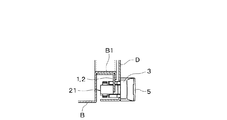
錠前ユニット29は、開口46を通して挿入されるキーの操作により、スライドプレート36を摺動させ、図5に示すように、ラッチレバー28を非係合位置へ回動操作することができる。この操作は、ソレノイドユニット30が電気的障害で動作不能のときにのみ、緊急的に行われる。   The lock unit 29 can slide the slide plate 36 by operating a key inserted through the opening 46 and rotate the latch lever 28 to the non-engagement position as shown in FIG. This operation is urgently performed only when the solenoid unit 30 is inoperable due to an electrical failure.

ソレノイドユニット30は、扉Dの背面側に位置して、ハンドルベース3の下端部に固着される支持板37上に設けられる。ソレノイドユニット30は、ソレノイド本体38と、それの鉄心に連結される接続金具39とからなる。ソレノイド本体38は、支持板37に固定され、接続金具39は、ラッチレバー28の操作部41に接続される。ソレノイド本体38に通電すると、図4に示すように、ラッチレバー28を引き下ろして非係合位置に保持し、常時は図1ないし図3に示すように、ラッチレバー28を解放して係合可能状態におく。ラッチレバー28が解放されているとき、フック部40が係合部26に係合して、レバーハンドル5が錠止される。   The solenoid unit 30 is located on the back side of the door D and is provided on a support plate 37 that is fixed to the lower end portion of the handle base 3. The solenoid unit 30 includes a solenoid body 38 and a connection fitting 39 connected to the iron core thereof. The solenoid body 38 is fixed to the support plate 37, and the connection fitting 39 is connected to the operation portion 41 of the latch lever 28. When the solenoid body 38 is energized, the latch lever 28 is pulled down and held in the non-engaged position as shown in FIG. 4, and the latch lever 28 can be released and engaged at all times as shown in FIGS. Put in state. When the latch lever 28 is released, the hook portion 40 engages with the engaging portion 26, and the lever handle 5 is locked.

リミットスイッチ42は、ハンドルベース3の裏側に固着され、それのヒンジレバーが、ハンドルベース3の開口47を介して、レバーハンドル5の押圧突起45に対面するように配置される。レバーハンドル5がロック位置にあるとき、リミットスイッチ42はソレノイドユニット30への給電回路を閉じているが、レバーハンドル5が起立すると、給電回路を開いてソレノイドユニット30への給電を停止する。   The limit switch 42 is fixed to the back side of the handle base 3, and the hinge lever thereof is disposed so as to face the pressing protrusion 45 of the lever handle 5 through the opening 47 of the handle base 3. When the lever handle 5 is in the locked position, the limit switch 42 closes the power supply circuit to the solenoid unit 30, but when the lever handle 5 stands up, the power supply circuit is opened to stop power supply to the solenoid unit 30.

LEDランプは、ハンドルベース3上の、レバーハンドル5の開口44に対応する位置に取り付けられ、ソレノイドユニット30への通電時に点灯し、それによって、ロックハンドル装置が解錠状態にあることを表示する。   The LED lamp is mounted on the handle base 3 at a position corresponding to the opening 44 of the lever handle 5 and is turned on when the solenoid unit 30 is energized, thereby indicating that the lock handle device is in the unlocked state. .

すなわち、レバーハンドル5がロック位置で錠止されている図3の状態で、解錠指令信号により、ソレノイドユニット30へ給電されると、図4に示すように、ラッチレバー28が引かれて、レバーハンドル5の係合部26が解放される。ソレノイドユニット30へは給電状態が維持される。係合部26が解放されても、レバーハンドル5は、ばね19によりロック位置に保持される。この間、LEDランプ43が点灯し解錠状態を表示する。この状態で、レバーハンドル5を引き上げると、リミットスイッチ42が切れてソレノイドユニット30への給電が絶たれ、ラッチレバー28が係合位置へ復帰する。レバーハンドル5を起立させて扉Dを開き、所要の作業終了後、再び扉Dを閉じる際に、レバーハンドル5を倒伏させると、自動的にラッチレバー28がレバーハンドル5の係合部26に係合してレバーハンドル5がロック位置に錠止される。   That is, when power is supplied to the solenoid unit 30 by the unlock command signal in the state of FIG. 3 in which the lever handle 5 is locked at the locked position, the latch lever 28 is pulled as shown in FIG. The engaging part 26 of the lever handle 5 is released. A power supply state is maintained for the solenoid unit 30. Even when the engaging portion 26 is released, the lever handle 5 is held in the locked position by the spring 19. During this time, the LED lamp 43 is turned on to display the unlocked state. When the lever handle 5 is pulled up in this state, the limit switch 42 is cut off, the power supply to the solenoid unit 30 is cut off, and the latch lever 28 returns to the engaged position. When the lever handle 5 is erected and the door D is opened, and the door D is closed again after the required work is completed, when the lever handle 5 is laid down, the latch lever 28 automatically engages with the engaging portion 26 of the lever handle 5. The lever handle 5 is engaged and locked in the locked position.

今、図1に示す非ロック状態において、レバーハンドル5は、ハンドルベース3から起立し、反転ばね19により、起立状態に保持されている。第1、第2クランプ体8,21のフック部10,23は、それぞれ第1、第2ストライク1,2から離脱している。直線L1は、基準直線Lの右下側にある。ソレノイドユニット30は通電されておらず、ラッチレバー28は係合位置にある。   Now, in the unlocked state shown in FIG. 1, the lever handle 5 stands from the handle base 3 and is held in the standing state by the reversing spring 19. The hook portions 10 and 23 of the first and second clamp bodies 8 and 21 are detached from the first and second strikes 1 and 2, respectively. The straight line L1 is on the lower right side of the reference straight line L. The solenoid unit 30 is not energized and the latch lever 28 is in the engaged position.

この状態から、反転ばね19に抗してレバーハンドル5を倒伏方向(時計方向)へ回転させると、図2に示す中間位置において反転ばね19が圧死点に達し、これを越えると、レバーハンドル5は倒伏方向へ付勢され、図3に示すロック位置に至り、自動的にラッチレバー28により錠止される。この間に、直線L1は、基準直線Lを上方へ越えて右上側に配置される。この状態でラッチレバー28が掛かっていない場合に、外部の衝撃や振動、扉の自重、固定枠体の内部圧力等によりフック部10,23が離脱方向(フック部10が図において時計方向、フック部23が図において反時計方向)への回転力を受けても、連結リンク14が回転できないので、フック部10,23がストライク1,2から離脱することはない。扉Dは2点でロックされるので良好な密閉状態が確保される。再び扉Dを開くには、ソレノイドユニット30に通電する必要がある。ソレノイドユニット30に通電するとLED43ランプが点灯する。ソレノイドユニット30が何らかの障害により動作しない場合には、キーにより錠前ユニット29を操作して、ラッチレバー28をレバーハンドル5の係合部26から外すことにより、レバーハンドル5を引き上げて、扉Dを開くことができる。   From this state, when the lever handle 5 is rotated counterclockwise (clockwise) against the reversing spring 19, the reversing spring 19 reaches the pressure dead center at the intermediate position shown in FIG. Is biased in the lying down direction, reaches the lock position shown in FIG. 3, and is automatically locked by the latch lever 28. During this time, the straight line L1 is disposed on the upper right side, exceeding the reference straight line L upward. In this state, when the latch lever 28 is not engaged, the hooks 10 and 23 are released in the direction of disengagement due to external impacts and vibrations, the weight of the door, the internal pressure of the fixed frame, etc. Even if the portion 23 receives a rotational force in the counterclockwise direction in the drawing, the connecting link 14 cannot rotate, so that the hook portions 10 and 23 do not detach from the strikes 1 and 2. Since the door D is locked at two points, a good sealed state is ensured. In order to open the door D again, it is necessary to energize the solenoid unit 30. When the solenoid unit 30 is energized, the LED 43 lamp is turned on. When the solenoid unit 30 does not operate due to some trouble, the lock unit 29 is operated by a key to release the latch lever 28 from the engaging portion 26 of the lever handle 5, thereby pulling up the lever handle 5 and opening the door D. Can be opened.

1 第1ストライク
2 第2ストライク
3 ハンドルベース
4 第1固定枢軸
5 レバーハンドル
6 駆動アーム
7 第2固定枢軸
8 第1クランプ体
9 基端部
10 フック部
11 受動肩部
12 ばね受け突起
13 第1可動枢軸
14 連結リンク
15 ばね受け突起
16 第2可動枢軸
17 第2連結リンク
18 第3可動枢軸
19 反転ばね
20 第3固定枢軸
21 第2クランプ体
22 基端部
23 フック部
24 受動肩部
25 第3可動枢軸
26 係合部
27 施錠ユニット
28 ラッチレバー
29 錠前ユニット
30 ソレノイドユニット
31 ラッチ収納空間
32 錠前収納空間
33 ラッチ軸
34 シリンダケース
35 ばね
36 スライドプレート
37 支持板
38 ソレノイド本体
39 接続金具
40 フック部
41 操作部
42 リミットスイッチ
43 LEDランプ
44 ランプ表示用開口
45 スイッチ押圧用突起
46 キー挿通用開口
B 固定枠体
B1 囲壁部
D 扉
L 基準直線
L1 第1、第2枢支点間を結ぶ直線
DESCRIPTION OF SYMBOLS 1 1st strike 2 2nd strike 3 Handle base 4 1st fixed pivot 5 Lever handle 6 Drive arm 7 2nd fixed pivot 8 1st clamp body 9 Base end part 10 Hook part 11 Passive shoulder part 12 Spring receiving protrusion 13 1st Movable pivot 14 Connection link 15 Spring receiving projection 16 Second movable pivot 17 Second connection link 18 Third movable pivot 19 Reversing spring 20 Third fixed pivot 21 Second clamp body 22 Base end 23 Hook 24 Passive shoulder 25 First 3 movable pivot 26 engaging portion 27 locking unit 28 latch lever 29 lock unit 30 solenoid unit 31 latch storage space 32 lock storage space 33 latch shaft 34 cylinder case 35 spring 36 slide plate 37 support plate 38 solenoid body 39 connection fitting 40 hook portion 41 Operation section 42 Limit switch 43 LED lamp 44 Flop display opening 45 switch pressing projection 46 key insertion opening B stationary frame element B1 periphery wall section D door L reference line L1 first, straight line connecting the second pivot point

Claims (3)

固定枠体側に設けられるストライクと;固定枠体側に枢支される扉を閉鎖したとき前記ストライクの前方に対面する位置において当該扉に固着されるハンドルベースと;扉の前面と平行な第1固定枢軸によって基端側においてハンドルベースに起伏自在に枢着されることによって、倒伏したロック位置と起立した非ロック位置との間を回転自在で、ロック位置において基端から先端へ上下方向に延びるように配置されると共に、前記第1固定枢軸よりも先端側の部位においてロック位置における後方へ延出する駆動アームを有するレバーハンドルと、
基端部と;基端部から前記ハンドルベースの背面側に突出するフック部と;基端部からフック部と反対方向へ延出する受動肩部とを有し;基端部が前記第1固定枢軸と平行な第2固定枢軸によってハンドルベースに枢着されると共に、受動肩部が連結リンクを介して前記レバーハンドルに連結されことによって当該レバーハンドル連動してロック位置と非ロック位置との間を正逆回転し、ロック位置においてフック部が前記ストライクに係合し、非ロック位置においてフック部がストライクから離脱するクランプ体と、
ロック位置における前記レバーハンドルに対面する位置において前記ハンドルベースに設けられる施錠ユニットと、を具備し、
前記レバーハンドルは、ロック位置において前記施錠ユニットに拘束される係合部を具備し、
前記施錠ユニットは、前記第1固定枢軸と平行なラッチ軸により前記ハンドルベースに枢支されることによりロック位置にある前記レバーハンドルの係合部に係合する係合位置と離脱する非係合位置との間を正逆回転自在で、常時は係合位置に回転付勢され、ロック位置へ倒伏回動する前記レバーハンドルの係合部に押されていったん非係合位置へ回転した後係合位置へ回転復元するラッチレバーと;前記ハンドルベースに固着され、キー操作により前記ラッチレバーを非係合位置へ回転操作可能な錠前ユニットと;前記ハンドルベースに固着され、通電時に前記ラッチレバーを非係合位置に保持し、常時はラッチレバーを解放するソレノイドユニットとを具備することを特徴とする扉用ロックハンドル装置。
A strike provided on the fixed frame side; a handle base fixed to the door at a position facing the front of the strike when the door pivotally supported on the fixed frame side is closed; a first fixed parallel to the front surface of the door By pivoting pivotally on the handle base at the base end side by the pivot, it can rotate between the fallen locked position and the standing unlocked position, and extends vertically from the base end to the distal end at the lock position. And a lever handle having a drive arm that extends rearward in the locked position at a position on the tip side of the first fixed pivot,
A proximal end portion; a hook portion projecting from the proximal end portion toward the back side of the handle base; a passive shoulder portion extending from the proximal end portion in a direction opposite to the hook portion; The second fixed pivot that is parallel to the fixed pivot is pivotally attached to the handle base, and the passive shoulder is connected to the lever handle via a connecting link, so that the lever handle is linked to the locked position and the unlocked position. A clamp body that rotates forward and backward, the hook portion engages with the strike in the locked position, and the hook portion disengages from the strike in the unlocked position;
A locking unit provided on the handle base at a position facing the lever handle at a locked position,
The lever handle includes an engaging portion that is restrained by the locking unit in a locked position;
The locking unit is pivotally supported on the handle base by a latch shaft that is parallel to the first fixed pivot, so that the locking unit is engaged with the engaging portion of the lever handle in the locked position and is disengaged. It can rotate forward and backward between the positions, and is normally urged to rotate to the engaged position, and is pushed by the engaging portion of the lever handle that rotates to the locked position, and then once rotated to the non-engaged position. A latch lever that is rotated and restored to a mating position; a lock unit that is fixed to the handle base and is capable of rotating the latch lever to a non-engagement position by a key operation; A door lock handle device comprising: a solenoid unit which is held in a non-engagement position and normally releases a latch lever.
前記施錠ユニットは、前記ハンドルベース上に前方へ露出するように固着され、前記ソレノイドユニットの通電時に点灯するLEDランプと;前記ハンドルベースに固着され、前記レバーハンドルがロック位置にあることを検知して前記LEDランプへの通電を絶つリミットスイッチと;をさらに具備し、
前記レバーハンドルは、ロック位置における前記LEDランプに対面する位置に、当該LEDランプを前方へ露出させる表示窓をさらに具備することを特徴とする請求項1に記載の扉用ロックハンドル装置。
The locking unit is fixed to the handle base so as to be exposed forward, and an LED lamp that is lit when the solenoid unit is energized; and is fixed to the handle base and detects that the lever handle is in the locked position. A limit switch that cuts off the power to the LED lamp;
2. The door lock handle device according to claim 1, further comprising a display window that exposes the LED lamp forward at a position facing the LED lamp in a lock position.
前記ラッチレバーは、基端側に前記ハンドルベースの後方へ延出する操作部を有し、先端側には、ロック位置へ倒伏回動する前記レバーハンドルの係合部に摺接してラッチレバーをいったん非係合位置へ回転させた後、ロック位置において当該係合部に係合するフック部を具備し、
前記施錠ユニットは、前記ラッチレバーの操作部に連結される接続部を具備することを特徴とする請求項1又は2に記載の扉用ロックハンドル装置。
The latch lever has an operation portion extending rearward of the handle base on the proximal end side, and on the distal end side, the latch lever is slidably contacted with an engagement portion of the lever handle that rotates to the lock position. Once it is rotated to the non-engagement position, it has a hook part that engages with the engagement part in the lock position,
The door locking handle device according to claim 1, wherein the locking unit includes a connection portion coupled to an operation portion of the latch lever.
JP2011043944A 2011-03-01 2011-03-01 Lock handle device for door Active JP5291738B2 (en)

Priority Applications (1)

Application Number Priority Date Filing Date Title
JP2011043944A JP5291738B2 (en) 2011-03-01 2011-03-01 Lock handle device for door

Applications Claiming Priority (1)

Application Number Priority Date Filing Date Title
JP2011043944A JP5291738B2 (en) 2011-03-01 2011-03-01 Lock handle device for door

Publications (2)

Publication Number Publication Date
JP2012180676A true JP2012180676A (en) 2012-09-20
JP5291738B2 JP5291738B2 (en) 2013-09-18

Family

ID=47012092

Family Applications (1)

Application Number Title Priority Date Filing Date
JP2011043944A Active JP5291738B2 (en) 2011-03-01 2011-03-01 Lock handle device for door

Country Status (1)

Country Link
JP (1) JP5291738B2 (en)

Cited By (4)

* Cited by examiner, † Cited by third party
Publication number Priority date Publication date Assignee Title
JP2017005042A (en) * 2015-06-08 2017-01-05 タキゲン製造株式会社 Multi-point tightening lock system and explosion-proof door using the same
JP2018150733A (en) * 2017-03-14 2018-09-27 日東工業株式会社 Clamp type locking device
CN109403719A (en) * 2018-12-03 2019-03-01 珠海优特电力科技股份有限公司 A kind of intelligent panel lock
CN113677113A (en) * 2020-05-13 2021-11-19 纬联电子科技(中山)有限公司 Handle mechanism and casing assembly comprising same

Citations (3)

* Cited by examiner, † Cited by third party
Publication number Priority date Publication date Assignee Title
JP2005002698A (en) * 2003-06-13 2005-01-06 Nitto Electric Works Ltd Clamp type locking device
JP2005256367A (en) * 2004-03-10 2005-09-22 Takigen Mfg Co Ltd Door lock handle device with fingerprint authenticating device
JP2006063673A (en) * 2004-08-27 2006-03-09 Takigen Mfg Co Ltd Lock handle device for double clamp type door

Patent Citations (3)

* Cited by examiner, † Cited by third party
Publication number Priority date Publication date Assignee Title
JP2005002698A (en) * 2003-06-13 2005-01-06 Nitto Electric Works Ltd Clamp type locking device
JP2005256367A (en) * 2004-03-10 2005-09-22 Takigen Mfg Co Ltd Door lock handle device with fingerprint authenticating device
JP2006063673A (en) * 2004-08-27 2006-03-09 Takigen Mfg Co Ltd Lock handle device for double clamp type door

Cited By (6)

* Cited by examiner, † Cited by third party
Publication number Priority date Publication date Assignee Title
JP2017005042A (en) * 2015-06-08 2017-01-05 タキゲン製造株式会社 Multi-point tightening lock system and explosion-proof door using the same
JP2018150733A (en) * 2017-03-14 2018-09-27 日東工業株式会社 Clamp type locking device
CN109403719A (en) * 2018-12-03 2019-03-01 珠海优特电力科技股份有限公司 A kind of intelligent panel lock
CN109403719B (en) * 2018-12-03 2023-11-28 珠海优特电力科技股份有限公司 Intelligent panel lock
CN113677113A (en) * 2020-05-13 2021-11-19 纬联电子科技(中山)有限公司 Handle mechanism and casing assembly comprising same
CN113677113B (en) * 2020-05-13 2022-09-30 纬联电子科技(中山)有限公司 Handle mechanism and casing assembly comprising same

Also Published As

Publication number Publication date
JP5291738B2 (en) 2013-09-18

Similar Documents

Publication Publication Date Title
JP5291738B2 (en) Lock handle device for door
KR100907641B1 (en) Mortise locking device
CN103168143A (en) Locking device with mechanical detection of closing and opening
JP6587835B2 (en) Multi-point tightening lock system and explosion-proof door using the same
JP2011234542A (en) Switch gear
JP2004143754A (en) Electric lock
CN109066439B (en) Handcart interlocking mechanism of five-prevention interlocking device
JP4586304B2 (en) Locking device for drawer type electrical equipment unit
JP2004143739A (en) Electric lock
JP3711663B2 (en) External circuit handle device for circuit breaker
CN206016488U (en) A kind of electronic sliding door lock with integrated morphology
JP4001242B2 (en) Lock handle device for double clamp type door.
JP5174928B2 (en) Lock handle device for door
EP2482399A2 (en) Interlocks for withdrawable breakers
JP4524654B2 (en) Vending machine door lock device
KR20190013724A (en) Exit device logging using combination lock
JP4629647B2 (en) Control handle device
JP5479217B2 (en) Locking and unlocking device for opening and closing body in article storage fixture
JP2014218836A (en) Front window opening/closing device for construction machine
JP6255580B2 (en) Handle device for electrical and electronic equipment storage box
JP2024099236A (en) Handle device
JP4893375B2 (en) Closed switchboard
CN216945733U (en) Safety window with novel locking device
JP2883610B1 (en) Clemon lock device with motor lock
JP3787455B2 (en) Circuit breaker with external operation device

Legal Events

Date Code Title Description
A977 Report on retrieval

Free format text: JAPANESE INTERMEDIATE CODE: A971007

Effective date: 20130301

TRDD Decision of grant or rejection written
A01 Written decision to grant a patent or to grant a registration (utility model)

Free format text: JAPANESE INTERMEDIATE CODE: A01

Effective date: 20130509

A61 First payment of annual fees (during grant procedure)

Free format text: JAPANESE INTERMEDIATE CODE: A61

Effective date: 20130607

R150 Certificate of patent or registration of utility model

Ref document number: 5291738

Country of ref document: JP

Free format text: JAPANESE INTERMEDIATE CODE: R150

R250 Receipt of annual fees

Free format text: JAPANESE INTERMEDIATE CODE: R250

R250 Receipt of annual fees

Free format text: JAPANESE INTERMEDIATE CODE: R250

R250 Receipt of annual fees

Free format text: JAPANESE INTERMEDIATE CODE: R250

R250 Receipt of annual fees

Free format text: JAPANESE INTERMEDIATE CODE: R250

R250 Receipt of annual fees

Free format text: JAPANESE INTERMEDIATE CODE: R250

R250 Receipt of annual fees

Free format text: JAPANESE INTERMEDIATE CODE: R250

R250 Receipt of annual fees

Free format text: JAPANESE INTERMEDIATE CODE: R250

R250 Receipt of annual fees

Free format text: JAPANESE INTERMEDIATE CODE: R250

R250 Receipt of annual fees

Free format text: JAPANESE INTERMEDIATE CODE: R250