JP2007289932A - Microporous membrane manufacturing method and device used for the same - Google Patents
Microporous membrane manufacturing method and device used for the same Download PDFInfo
- Publication number
- JP2007289932A JP2007289932A JP2007073421A JP2007073421A JP2007289932A JP 2007289932 A JP2007289932 A JP 2007289932A JP 2007073421 A JP2007073421 A JP 2007073421A JP 2007073421 A JP2007073421 A JP 2007073421A JP 2007289932 A JP2007289932 A JP 2007289932A
- Authority
- JP
- Japan
- Prior art keywords
- wetting agent
- microporous membrane
- air
- microporous
- film
- Prior art date
- Legal status (The legal status is an assumption and is not a legal conclusion. Google has not performed a legal analysis and makes no representation as to the accuracy of the status listed.)
- Pending
Links
Images


Landscapes
- Separation Using Semi-Permeable Membranes (AREA)
Abstract
Description
本発明は微孔性膜の製造方法及び装置に係り、特に製薬工業、食品工業、電子工業、原子力工業などの分野で用いられるポリスルホン系の微孔性膜の製造方法及び装置に関する。 The present invention relates to a method and apparatus for producing a microporous membrane, and more particularly to a method and apparatus for producing a polysulfone-based microporous membrane used in fields such as pharmaceutical industry, food industry, electronics industry, and nuclear industry.
製薬工業、食品工業などの分野では、0.1〜5μm程度の微粒子や菌を除去するために微孔性膜が用いられる。この微孔性膜は一般に、セルロースエステル、脂肪族ポリアミド、ポリフルオロカーボン、ポリスルホン、ポリプロピレン等を原料として製造される。 In fields such as the pharmaceutical industry and the food industry, microporous membranes are used to remove fine particles and bacteria of about 0.1 to 5 μm. This microporous membrane is generally produced using cellulose ester, aliphatic polyamide, polyfluorocarbon, polysulfone, polypropylene or the like as a raw material.
微孔性膜には、微孔の孔径が膜厚方向に均一な対称膜と、孔径が膜厚方向に変化する非対称膜とがある。特許文献1には、膜の内部に最小孔径層を有する微孔性膜を製造する方法が記載されている。この微孔性膜は、膜の表面の孔径が内部の孔径よりも大きいので、濾過抵抗が小さく、且つ、微粒子や菌の補足効率が高い。また、特許文献1の微孔性膜は、その表面を欠損しても濾過性能が劣化せず、常に高い濾過性能を維持することができる。 Microporous membranes include symmetric membranes in which the pore diameter is uniform in the film thickness direction, and asymmetric membranes in which the pore diameter varies in the film thickness direction. Patent Document 1 describes a method for producing a microporous membrane having a minimum pore size layer inside the membrane. This microporous membrane has a smaller pore resistance on the surface of the membrane than the internal pore size, and thus has a low filtration resistance and a high efficiency of capturing fine particles and bacteria. Further, the microporous membrane of Patent Document 1 does not deteriorate the filtration performance even if the surface is lost, and can always maintain a high filtration performance.
このような微孔性膜は、たとえばカートリッジに組み込まれて使用される(特許文献2参照)。カートリッジは通常、微孔性膜の組み込み後に完全性試験が行われる。この試験は、微孔性膜にピンホールや破れなどの欠陥がないことを確認するためであり、たとえばバブルポイント法、拡散流量法、圧力保持法が用いられる。いずれの方法においても、微孔性膜を濡らした状態で試験が行われる。しかし、カートリッジの組み込まれた微孔性膜は、カートリッジとのシール部、すなわち微孔性膜の幅方向の端部において濡れにくいという問題がある。このため、特許文献2では、幅方向の両端部に濡れ剤を塗布している。
ところで、濡れ剤にはポリビニルピロリドンなどの親水性ポリマーが用いられるため、そのままではカビ菌が発生しやすいという問題がある。特に微孔性膜を食品製造工場や医薬品製造工場で使用する場合には、濡れ剤や膜の原料に防腐剤を入れることができないため、濡れ剤の塗布部分にカビ菌が発生しやすいという問題がある。 By the way, since a hydrophilic polymer such as polyvinylpyrrolidone is used as the wetting agent, there is a problem that mold fungi are easily generated as it is. In particular, when microporous membranes are used in food manufacturing plants and pharmaceutical manufacturing plants, it is not possible to put preservatives in the wetting agent or the raw material of the membrane. There is.
このため、従来は、微孔性膜をカートリッジに組み込んだ後に、カートリッジ全体を殺菌処理しなければならなかった。しかしながら、カートリッジに組み込んだ後であるため、微孔性膜の完全な殺菌処理が難しいという問題があり、微孔性膜の製造の段階で、カビ菌の発生しにくい微孔性膜が欲しいという要望がある。 For this reason, conventionally, after the microporous membrane is incorporated in the cartridge, the entire cartridge has to be sterilized. However, there is a problem that it is difficult to completely sterilize the microporous membrane after it is assembled in the cartridge, and there is a need for a microporous membrane that does not easily generate mold at the stage of manufacturing the microporous membrane. There is a request.
本発明はこのような事情に鑑みて成されたもので、濡れ剤の塗布部分からのカビ菌の発生を防止できる微孔性膜を製造する製造方法及び装置を提供することを目的とする。 The present invention has been made in view of such circumstances, and an object of the present invention is to provide a production method and apparatus for producing a microporous membrane capable of preventing the generation of mold fungi from the application part of the wetting agent.
請求項1に記載の発明は前記目的を達成するために、微孔性膜の表面に濡れ剤を塗布する濡れ剤塗布工程と、前記濡れ剤塗布工程で塗布した濡れ剤を乾燥させる濡れ剤乾燥工程とを有する微孔性膜の製造方法において、前記濡れ剤乾燥工程は、HEPAフィルタを通過したエアを前記微孔性膜の表面に吹きつけることを特徴とする。 In order to achieve the above object, the invention according to claim 1 is a wetting agent application step for applying a wetting agent to the surface of the microporous membrane, and a wetting agent drying for drying the wetting agent applied in the wetting agent application step. In the method for producing a microporous membrane having a step, the wetting agent drying step blows air that has passed through a HEPA filter onto the surface of the microporous membrane.
本発明の発明者は、濡れ剤の塗布部でカビ菌が発生する主な原因が、塗布後の濡れ剤を乾燥させるためのエアにあり、このエアをHEPAフィルタに通過させて微孔性膜の表面に吹きつけることによって、濡れ剤の塗布部分からカビ菌が発生することを防止できるという知見を得た。 The inventor of the present invention is that the main cause of mold fungus generation in the application part of the wetting agent is the air for drying the wetting agent after application, and this air is passed through the HEPA filter to pass through the microporous membrane. It has been found that by spraying on the surface of the mold, mold fungi can be prevented from being generated from the application part of the wetting agent.
本発明はこのような知見に基づいて成されたものであり、濡れ剤を塗布した微孔性膜に、HEPAフィルタを通過したエアを吹きつけて濡れ剤を乾燥させるようにしたので、濡れ剤の塗布部分からカビ菌が発生することを防止することができる。 The present invention has been made on the basis of such knowledge, and the wetting agent is dried by blowing the air that has passed through the HEPA filter onto the microporous film coated with the wetting agent. It is possible to prevent the occurrence of mold fungi from the coated part.
請求項2に記載の発明は請求項1の発明において、前記微孔性膜は、食品工業用又は製薬工業用であることを特徴とする。食品工業や製薬工業で用いられる微孔性膜は、防腐剤を用いることができないのでカビ菌が発生しやすいが、このような用途の微孔性膜の製造に本発明を適用するとカビ菌の発生を防止でき、効果的である。 The invention according to claim 2 is the invention according to claim 1, wherein the microporous membrane is for the food industry or the pharmaceutical industry. Microporous membranes used in the food and pharmaceutical industries are prone to mold fungi because preservatives cannot be used. However, when the present invention is applied to the production of microporous membranes for such uses, Occurrence can be prevented and it is effective.
請求項3に記載の発明は前記目的を達成するために、微孔性膜の表面に濡れ剤を塗布する濡れ剤塗布装置と、前記濡れ剤塗布装置によって塗布された濡れ剤を乾燥させる濡れ剤乾燥装置とを有する微孔性膜の製造装置において、前記濡れ剤乾燥装置は、その外面に複数の噴射口を有し、該噴射口からエアを噴射することによって前記微孔性膜を前記外面から浮上させて支持する無接触搬送ローラと、前記無接触搬送ローラにエア供給ラインを介して接続され、前記噴射口から噴射されるエアを前記無接触搬送ローラに送気する送気手段と、前記エア供給ライン上に配設されたHEPAフィルタと、を備えたことを特徴とする。 In order to achieve the above object, the invention according to claim 3 is a wetting agent application device for applying a wetting agent to the surface of the microporous membrane, and a wetting agent for drying the wetting agent applied by the wetting agent application device. In the apparatus for producing a microporous membrane having a drying device, the wetting agent drying device has a plurality of injection ports on an outer surface thereof, and the microporous membrane is applied to the outer surface by injecting air from the injection ports. A non-contact conveying roller that floats and supports from the above, and an air supply means that is connected to the non-contact conveying roller via an air supply line and supplies the air ejected from the ejection port to the non-contact conveying roller; And an HEPA filter disposed on the air supply line.
本発明によれば、濡れ剤を塗布した微孔性膜に、HEPAフィルタを通過させたエアを吹きつけて濡れ剤を乾燥させるようにしたので、濡れ剤の塗布部分からカビ菌が発生することを防止することができる。 According to the present invention, since the wetting agent is dried by blowing the air that has passed through the HEPA filter to the microporous membrane to which the wetting agent is applied, mold fungi are generated from the application portion of the wetting agent. Can be prevented.
以下添付図面に従って本発明に係る微孔性膜の製造方法及び装置の好ましい実施形態について説明する。 Preferred embodiments of a method and apparatus for producing a microporous membrane according to the present invention will be described below with reference to the accompanying drawings.
図1は本実施の形態における微孔性膜の製造装置の構成を模式的に示している。同図に示す溶解タンク12は、微孔性膜形成用のドープを調製するタンクであり、この溶解タンク12の内部で、膜形成用のポリマーが溶媒に溶解されてドープが調製される。溶解タンク12にはジャケット14が取りつけられており、このジャケット14に熱媒体を循環させることによって、溶解タンク12内のドープが一定温度に保持される。
FIG. 1 schematically shows the configuration of a microporous membrane manufacturing apparatus according to the present embodiment. A
溶解タンク12内のドープは、その温度及び溶解状態が安定した状態で、送液ポンプ16によって塗布装置のダイ18に送られる。そして、ドープは、ダイ18の先端から帯状支持体20に向けて連続的に吐出される。
The dope in the
帯状支持体20は、たとえばポリエステルフィルムから成り、ロール状に巻回されて巻戻ローラ22に装着されている。帯状支持体20は、巻戻ローラ22から巻き戻され、ドラム24に巻きかけられて支持される。そして、この帯状支持体20は、後述の凝固槽26内でガイドローラ28、28にガイドされた後、ガイドローラ30、剥離ローラ32を経て、巻取ローラ34によってロール状に巻回される。
The belt-
前述のダイ18から吐出されたドープは、ドラム24に巻きかけ支持された帯状支持体20上に流延塗布される。これにより、帯状支持体20の表面にドープの液膜(後に微孔性膜44となる膜)が形成される。
The dope discharged from the
ドープの液膜が形成された帯状支持体20は、まず、調湿ゾーン36を鉛直に下方向に走行する。調湿ゾーン36は、そのケーシング38が、ドラム24から凝固槽26までの帯状支持体20の液膜側表面を覆うように形成されている。また、調湿ゾーン36の内部は、調湿されたエアが帯状支持体20の走行方向に(すなわち下方に向けて)送風されている。具体的には、調湿ゾーン36の上部に調湿エアの給気口36Aが設けられ、調湿ゾーン36の下部に調湿エアの排気口36Bが設けられる。給気口36Aと排気口36Bには、循環ダクト40が接続されており、この循環ダクト40に空調機42が設けられる。空調機42は、排気口36Bからエアを吸引し、このエアの温湿度を調節した後、給気口36Aに送気する。これにより、所定の温室度に調節された調湿エアが調湿ゾーン36に送気され、調湿ゾーン36の内部が所定の温湿度に維持される。
The belt-
なお、調湿エアは、温度15〜60℃で、相対湿度10〜80%、風速0.2〜4m/secの範囲内で調節することが好ましい。また、調湿ゾーン36では、帯状支持体20の表面の液膜が、調湿エアに2〜17秒間、曝されることが好ましい。
In addition, it is preferable to adjust humidity control air within the range of the relative humidity of 10-80% and the wind speed of 0.2-4 m / sec at the temperature of 15-60 degreeC. Moreover, in the
調湿ゾーン36を通過することによって帯状支持体20上の液膜は、表面から内部に向かってコアセルベーションを起こし、微細なコアセルベーション相を液膜の表面から内部に形成する。すなわち、調湿ゾーン36では、空気中から非溶媒蒸気(たとえば水分)を吸収せしめる一方で溶媒を蒸発させ、表面近傍にのみ相分離状態を作り出すので、後述の凝固槽26で微孔性膜を形成した際に、膜の内部に微細孔を形成し、膜の表面に比較的大きな細孔を形成することができる。
By passing through the
調湿ゾーン36を通過した帯状支持体20は、凝固槽26内のガイドローラ28、28にガイドされて走行することによって、凝固槽26内の凝固液に浸漬される。凝固液としては、ドープのポリマーに対して非溶媒であり、且つ、ポリマーの溶媒に相溶性を有する液(たとえば水)が好ましい。この凝固液に浸漬されることによって、帯状支持体20の表面の液膜は、溶媒が溶けて凝固液に置換され、溶媒置換が行われる。そして、調湿ゾーン36で形成されたコアセルベーション相を微細孔として固定させると同時に、液膜の相分離によって微細孔以外の細孔を形成し、微孔性膜44が形成される。
The belt-
微孔性膜44は帯状支持体20に密着した状態で凝固槽26から導出される。そして、剥離ローラ32によって帯状支持体20が微孔性膜44から剥離され、剥離後の帯状支持体20が巻取ローラ34に巻き取られる。
The
一方、剥離後の微孔性膜44は、フィードローラ46を駆動することによって走行し、水洗槽48に導入される。水洗槽48の内部には、水洗液中にターンバー50、50…が設けられており、このターンバー50、50…によって微孔性膜44がガイドされる。そして、微孔性膜44が水洗槽48内の水洗液中を走行することによって、微孔性膜44に付着した溶媒等が洗い落とされる。
On the other hand, the peeled
水洗後の微孔性膜44は、乾燥室52に送られる。乾燥室52には、乾燥ドラム54、54…が設けられており、この乾燥ドラム54、54…に巻きかけられることによって微孔性膜44が乾燥される。
The
乾燥後の微孔性膜44は、濡れ剤の塗布室56に送られる。塗布室56には、濡れ剤の調製タンク58が設けられており、この調製タンク58によって濡れ剤が調製される。濡れ剤としては、食品や医薬品に混入しても安全であり、且つ、水に容易に洗浄除去可能な材料が好ましい。たとえばポリビニルピロリドン及びその誘導体、メチルセルロース、ヒドロキシメチルセルロース及びそれらの誘導体、エチルセルロース、ヒドロキシエチルセルロース及びそれらの誘導体などの親水性ポリマーは、安全性が高く、濡らし効果が高く、且つ水洗で容易に洗い落とせるので好ましい。同様の理由から、炭素数が6〜24のアルキルスルホン酸塩及び蔗糖高級脂肪酸エステルなどの界面活性剤も好ましい。このアルキルスルホン酸塩としては、ナトリウム塩、カリウム塩及びリチウム塩が好ましく、蔗糖脂肪酸エステルの脂肪酸は、炭素数は6〜24が好ましい。
The
調製タンク58内の濡れ剤は、不図示のポンプによってチューブ60を介して送液される。チューブ60の先端には、フェルト等から成るハケ部材62が設けられており、このハケ部材62が、ガイドローラ64、64にガイドされた微孔性膜44の幅方向の両端部に接触するようになっている。これにより、微孔性膜44の幅方向の両端部に濡れ剤が塗布される。
The wetting agent in the
濡れ剤の塗布量としては、たとえばポリビニルピロリドン及びその誘導体の場合、1〜6g/m2が好ましく、2〜4g/m2がより好ましい。メチルセルロース、ヒドロキシメチルセルロース及びそれらの誘導体の場合には0.1〜1g/m2が好ましく、0.2〜0.6g/m2がより好ましい。界面活性剤の場合には、0.05〜0.1g/m2が好ましく、0.1〜0.3g/m2がより好ましい。塗布する位置は、膜のそれぞれの端から数ミリメートルだけでよい。 As a coating amount of the wetting agent, for example, in the case of polyvinylpyrrolidone and derivatives thereof, 1 to 6 g / m 2 is preferable, and 2 to 4 g / m 2 is more preferable. In the case of methyl cellulose, hydroxymethyl cellulose and derivatives thereof, 0.1 to 1 g / m 2 is preferable, and 0.2 to 0.6 g / m 2 is more preferable. If the surfactant is preferably 0.05~0.1g / m 2, 0.1~0.3g / m 2 is more preferable. The application position need only be a few millimeters from each end of the membrane.
なお、濡れ剤の塗布方法は、上記の方法に限定されるものではなく、たとえば、濡れ剤をスポンジや布に染み込ませたものを微孔性膜44に接触させることによって塗布したり、ビードコータ、グラビアコータ、バーコーターなどの既知の塗布方法で塗布したりしてもよい。
The method of applying the wetting agent is not limited to the above method. For example, the wetting agent may be applied by bringing a wetting agent soaked in a sponge or cloth into contact with the
濡れ剤が塗布された微孔性膜44は、濡れ剤の乾燥室66に送られる。乾燥室66には、無接触搬送ドラム68、68が設けられており、このドラム68、68の外周面には、エアを吹き出す多数の孔が設けられる。微孔性膜44は、このドラム68、68に巻きかけられることによって、無接触で支持されて搬送され、微孔性膜44の表面の濡れ剤が乾燥処理される。
The
濡れ剤が乾燥した微孔性膜44は、所定の温湿度に調節された調整室70内をガイドローラ72、72…にガイドされて走行した後、巻取室74に送られてロール状に巻き取られる。
The
次に本発明の特徴部分である濡れ剤の乾燥工程について説明する。図2は、濡れ剤乾燥工程を模式的に示したものである。図2に示す濡れ剤乾燥室66には、ドラム(無接触搬送ローラに相当)68、68とガイドローラ69、69が設けられている。濡れ剤乾燥室66の内部において微孔性膜44は、その表面側(濡れ剤の塗布面側)がドラム68、68によって無接触でガイドされ、裏面側がガイドローラ69、69によって直接接触してガイドされて搬送される。なお、ドラム68とガイドローラ69の個数及び配置は図2に限定されるものではなく、たとえば一個又は三個以上のドラム68を設けてもよい。
Next, the drying process of the wetting agent, which is a characteristic part of the present invention, will be described. FIG. 2 schematically shows the wetting agent drying step. In the wetting
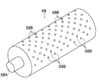
ドラム68は、図3に示すように円筒状に形成される。ドラム68の一方の側面(不図示)は封止され、もう一方の側面は給気口68Aが設けられており、この給気口68Aからドラム68の内部にエアが給気される。また、ドラム68の外周面には、多数の貫通孔68B、68B…が形成されており、ドラム68の内部に給気されたエアを貫通孔68B、68B…から外部に向けて噴射できるようになっている。貫通孔68B、68B…は、ドラム68の外周面のうち、微孔性膜44がラップする範囲において(すなわち、微孔性膜44が対向する範囲において)、均等な間隔で千鳥状に配置されている。これにより、ドラム68にラップされた微孔性膜44を、貫通孔68Bから噴射したエアによって安定して浮上支持することができる。なお、ドラム68の内部にその内部空間を幅方向に区切る規制板(不図示)を幅方向に移動自在に設け、この規制板を微孔性膜44の幅方向の端部位置に合わせるとよい。この場合、規制板の内側にエアを供給することによって、微孔性膜44に対向する貫通孔68B、68B…のみからエアが噴射されるので、微孔性膜44をより安定して浮上支持することができる。
The
図2に示すように、ドラム68、68の給気口68A、68Aには、送気ライン82、82が接続される。この送気ライン82、82は、ヒータユニット88、フィルタユニット86を介して、ファン84の送風口に接続されている。ファン84は、その吸気口が吸気ライン83を介して乾燥室66に連通される。したがって、ファン84を駆動することによって乾燥室66内のエアが吸気ライン83に吸い込まれ、送気ライン82を介してドラム68、68の給気口68A、68Aに送気される。
As shown in FIG. 2,
送気ライン82に配設されたヒータユニット88は、送気ライン82内のエアを所望の温度に加熱する装置である。このヒータユニット88によって、送気ライン82を流れるエアが、濡れ剤の乾燥に適した温度に調節される。
The
一方、フィルタユニット86は、その内部にHEPAフィルタ(High Efficiency Particulate Air)が設けられている。HEPAフィルタは、0.3μmの微粒子を99.97%捕集除去できる集塵力を有しており、このHEPAフィルタにエアを通過させることによって、送気ライン82内からカビ菌を捕集除去することができる。したがって、除菌したエアをドラム68に供給することができる。
On the other hand, the
上記の如く構成された濡れ剤乾燥工程によれば、除菌したエアがドラム68に供給され、このエアがドラム68の貫通孔68Bから噴射されて濡れ剤の塗布面に吹きつけられるので、未乾燥の濡れ剤にカビ菌が付着することを防止できる。したがって、濡れ剤の塗布部分からカビ菌が発生することを防止できる。
According to the wetting agent drying step configured as described above, the sterilized air is supplied to the
なお、上記のHEPAフィルタにヒノキチオール等の抗菌成分を含有させると、除菌性能をさらに向上させることができる。 In addition, when antibacterial components such as hinokitiol are contained in the above HEPA filter, the sterilization performance can be further improved.
また、上述した実施形態において、ドラム68に供給するエアだけでなく、濡れ剤乾燥室66の内部に給気するエアもHEPAフィルタで除菌するとよい。これにより、除菌した雰囲気中で濡れ剤乾燥工程が行われるので、未乾燥の濡れ剤にカビ菌が付着することをさらに確実に防止することができる。よって、濡れ剤の塗布部分からカビ菌が発生することをさらに確実に防止することができる。
In the above-described embodiment, not only the air supplied to the
また、上述した実施形態において、濡れ剤の塗布後の工程を全て除菌雰囲気中で行うとよい。すなわち、濡れ剤塗布室56、濡れ剤乾燥室66、調整室70、巻取室74に給気するエアをHEPAで除菌するとよい。これにより、濡れ剤の塗布部分からカビ菌が発生することをさらに確実に防止することができる。
In the above-described embodiment, all steps after the application of the wetting agent may be performed in a sterilizing atmosphere. That is, the air supplied to the wetting
なお、上述した実施形態で示した濡れ剤乾燥工程に加えて、図4〜図7に示す濡れ剤調整工程及び濡れ剤塗布工程を組み合わせると、濡れ剤の塗布部分からカビ菌が発生することをさらに確実に防止することができる。 In addition to the wetting agent drying process shown in the above-described embodiment, when the wetting agent adjustment process and the wetting agent application process shown in FIGS. 4 to 7 are combined, mold fungi are generated from the application part of the wetting agent. Furthermore, it can prevent reliably.
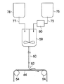
図4は、濡れ剤調製工程及び濡れ剤塗布工程の一例を模式的に示したものである。以下、濡れ剤として、ポリビニルピロリドンとイオン交換水とを混合して調製する例を示す。 FIG. 4 schematically shows an example of the wetting agent preparation step and the wetting agent application step. Hereinafter, an example in which polyvinyl pyrrolidone and ion-exchanged water are mixed as a wetting agent will be shown.
図4に示すように、調製タンク58は、配管75を介してイオン交換水のタンク76に接続されており、このタンク76内のイオン交換水が不図示の送液手段によって送液され、配管75を介して調製タンク58に供給される。また、調製タンク58は、配管77を介してポリビニルピロリドンのタンク78に接続されており、このタンク78内のポリビニルピロリドンが不図示の送液手段によって送液され、配管77を介して調製タンク58に供給される。
As shown in FIG. 4, the
イオン交換水のタンク76と調製タンク58との間の配管75には、濾過装置80が設けられている。濾過装置80の内部には、孔径0.1〜0.7μmのフィルタ(不図示)が設けられており、配管75を流れるイオン交換水はフィルタを通過することによって濾過される。これにより、イオン交換水の内部から、サイズ0.8μm以上であるカビ菌が確実に除去され、調製タンク58に供給される。
A
調製タンク58には、濾過されたイオン交換水と、タンク78内のポリビニルピロリドンが計量されて送液される。これにより、濡れ剤として、所定濃度(たとえば5%)のポリビニルピロリドン溶液が調製される。調製された濡れ剤は、チューブ60を介してハケ部材62に送液され、ハケ部材62によって微孔性膜44の幅方向の両端部に塗布される。
The filtered ion exchange water and the polyvinyl pyrrolidone in the
このように調製前のイオン交換水を濾過処理すると、イオン交換水は、その内部に存在するカビ菌が濾過処理によって捕集除去されるので、調製後の濡れ剤からはカビ菌を発生しない。したがって、この調整後の濡れ剤を微孔性膜44に塗布し、さらに上述した濡れ剤乾燥工程で濡れ剤を乾燥させることによって、濡れ剤の塗布部分からカビ菌が発生することをより確実に防止することができる。
When ion-exchanged water before preparation is filtered in this way, mold bacteria present in the ion-exchanged water are collected and removed by the filtration process, so mold fungi are not generated from the prepared wetting agent. Therefore, by applying the adjusted wetting agent to the
図5は、濡れ剤調製工程及び塗布工程の別の実施形態を模式的に示している。同図に示す濾過装置80は、チューブ60に配設されている。この濾過装置80の内部には、孔径0.1〜0.7μmのフィルタが設けられており、このフィルタによって調製後の濡れ剤が濾過処理される。したがって、調製後の濡れ剤に含まれるカビ菌を濾過装置80によって捕集除去することができ、カビ菌のない濡れ剤を微孔性膜44に塗布することができる。よって、上述した濡れ剤乾燥工程と組み合わせることによって、微孔性膜44の濡れ剤の塗布部分からカビ菌が発生することをより確実に防止することができる。
FIG. 5 schematically shows another embodiment of the wetting agent preparation step and the coating step. A
なお、図4、図5に示した工程では濾過処理回数を一回としたが濾過処理の回数はこれに限定するものではなく、複数回行うようにしてもよい。また、図4に示したイオン交換水の濾過処理と、図5に示した濡れ剤の濾過処理とを両方行うようにしてもよい。 In the steps shown in FIGS. 4 and 5, the number of filtration processes is one, but the number of filtration processes is not limited to this and may be performed a plurality of times. Moreover, you may make it perform both the filtration process of the ion exchange water shown in FIG. 4, and the filtration process of the wetting agent shown in FIG.
図6は、濡れ剤調製工程及び塗布工程の別の実施形態を模式的に示している。同図に示すタンク76には、ジャケット79が装着されており、このジャケット79の内部に所望の温度に加熱制御した熱媒体(蒸気や温水など)が必要に応じて供給されるようになっている。これにより、タンク76内のイオン交換水を加熱して殺菌することができる。したがって、カビ菌のないイオン交換水を用いて濡れ剤の調製を行うので、カビ菌のない濡れ剤を微孔性膜44に塗布することができ、上述した濡れ剤乾燥工程と組み合わせることによって、微孔性膜44の濡れ剤の塗布部分からカビ菌が発生することをより確実に防止することができる。
FIG. 6 schematically shows another embodiment of the wetting agent preparation step and the application step. The
なお、図6の実施形態は、タンク76内のイオン交換水を加熱して殺菌するようにしたが、調製前のイオン交換水を加熱して殺菌するのであればよく、たとえば配管75にジャケットを装着することによって配管75内のイオン交換水を加熱して殺菌するようにしてもよい。また、イオン交換水の加熱殺菌手段として、ジャケット79以外、たとえばヒーターや熱交換器などを用いてもよい。
In the embodiment of FIG. 6, the ion exchange water in the
図7は、濡れ剤調製工程及び塗布工程の別の実施形態を模式的に示している。同図に示すタンク58には、ジャケット59が装着されており、このジャケット59の内部に所望の温度に加熱制御した熱媒体(蒸気や温水など)が必要に応じて供給されるようになっている。これにより、タンク58内の調製後の濡れ剤を加熱して殺菌することができる。したがって、カビ菌のない濡れ剤を微孔性膜44に塗布することができ、上述したカビ菌の付着のない濡れ剤乾燥工程と組み合わせることによって、微孔性膜44の濡れ剤の塗布部分からカビ菌が発生することをより確実に防止することができる。
FIG. 7 schematically shows another embodiment of the wetting agent preparation step and the application step. The
なお、図7の実施形態は、調製タンク58内の濡れ剤を加熱して殺菌するようにしたが、調製後の濡れ剤を加熱して殺菌するのであればよく、たとえば、チューブ60にジャケットを装着することによってチューブ60内の濡れ剤を加熱して殺菌するようにしてもよい。また、濡れ剤の加熱殺菌手段として、ジャケット59以外、たとえばヒーターや熱交換器などを用いてもよい。
In the embodiment of FIG. 7, the wetting agent in the
また、イオン交換水の加熱殺菌手段と、濡れ剤の加熱殺菌手段の両方を設けてもよい。さらに、イオン交換水の加熱殺菌手段や濡れ剤の加熱殺菌手段に、上述したイオン交換水の濾過装置や濡れ剤の濾過装置を組み合わせて用いてもよい。いずれの組み合わせの場合にも、カビ菌のない濡れ剤を微孔性膜44に塗布することができるので、上述したカビ菌の付着のない濡れ剤乾燥工程と組み合わせることによって、微孔性膜44の濡れ剤の塗布部分からカビ菌が発生することをより確実に防止することができる。
Moreover, you may provide both the heat-sterilization means of ion-exchange water, and the heat-sterilization means of a wetting agent. Further, the ion exchange water heat sterilization means and the wetting agent heat sterilization means may be used in combination with the ion exchange water filtration device and the wetting agent filtration device described above. In any combination, since the wetting agent without mold fungus can be applied to the
なお、上述した実施形態において、濡れ剤が接触する部分とその原料が接触する部分(すなわち、調製タンク58、タンク76、78、配管75、77、濾過装置80、チューブ60及びハケ部材62)を、使用前に殺菌処理することが好ましい。殺菌処理方法は特に限定するものではないが、たとえば、エタノール溶液(エタノール70%以上が好ましい)によって殺菌処理することが好ましい。また、沸騰水によって加熱殺菌するようにしてもよい。
In the above-described embodiment, the portion where the wetting agent contacts and the portion where the raw material contacts (that is, the
以下に、本発明で用いられる微孔性膜形成用のドープについて説明する。ドープには、膜形成用ポリマーが含まれており、このポリマーを、良溶媒、または良溶媒と非溶媒の混合溶媒、若しくはポリマーに対する溶解性の異なる複数種の溶媒の混合液に溶解することによって作製される。 The dope for forming a microporous film used in the present invention will be described below. The dope contains a film-forming polymer, and the polymer is dissolved in a good solvent, a mixed solvent of a good solvent and a non-solvent, or a mixture of a plurality of solvents having different solubility in the polymer. Produced.
ポリマーの種類は特に限定するものではなく、微孔性膜の用途等に合わせて選択される。たとえば、ポリマーとして、セルロースアセテート、ニトロセルロース、ポリスルホン、スルホン化ポリスルホン、ポリエーテルスルホン、ポリアクリロニトリル、スチレン−アクリロニトリルコポリマー、スチレン−ブタジエンコポリマー、エチレン−酢酸ビニルコポリマーのケン化物、ポリビニルアルコール、ポリカーボネート、オルガノシロキサン−ポリカーボネートコポリマー、ポリエステルカーボネート、オルガノポリシロキサン、ポリフェニレンオキシド、ポリアミド、ポリイミド、ポリアミドイミド、ポリベンズィミダゾール等をあげることができる。 The type of polymer is not particularly limited and is selected according to the use of the microporous membrane. For example, as the polymer, cellulose acetate, nitrocellulose, polysulfone, sulfonated polysulfone, polyethersulfone, polyacrylonitrile, styrene-acrylonitrile copolymer, styrene-butadiene copolymer, saponified ethylene-vinyl acetate copolymer, polyvinyl alcohol, polycarbonate, organosiloxane -Polycarbonate copolymers, polyester carbonates, organopolysiloxanes, polyphenylene oxides, polyamides, polyimides, polyamideimides, polybenzimidazoles and the like.
また、溶媒は、ポリマーの種類等によって異なるが、凝固液に速やかに置換されるものが好ましい。多くの場合、凝固液として、水及び/又は水に相溶する有機溶媒が使用されるので、凝固液と相溶性のある極性溶媒を使用することが好ましい。たとえば、膜形成用ポリマーがポリスルホンの場合、ジオキサン、テトラヒドロフラン、ジメチルホルムアミド、ジメチルアセトアミド、N−メチル−2−ピロリドン、或いはこれらの混合溶媒が用いられる。また、ポリマーがポリアクリロニトリルの場合には、ジオキサン、N−メチル−2−ピロリドン、ジメチルホルムアミド、ジメチルアセトアミド、ジメチルスルホキシド等が好ましく、ポリマーがポリアミドの場合には、ジメチルホルムアミドやジメチルアセトアミド等が好ましく、ポリマーがセルロースアセテートの場合には、アセトン、ジオキサン、テトラヒドロフラン、N−メチル−2−ピロリドン等が好ましい。 Moreover, although a solvent changes with kinds etc. of a polymer, what is rapidly substituted by coagulating liquid is preferable. In many cases, water and / or an organic solvent compatible with water are used as the coagulation liquid, and therefore it is preferable to use a polar solvent compatible with the coagulation liquid. For example, when the film-forming polymer is polysulfone, dioxane, tetrahydrofuran, dimethylformamide, dimethylacetamide, N-methyl-2-pyrrolidone, or a mixed solvent thereof is used. Further, when the polymer is polyacrylonitrile, dioxane, N-methyl-2-pyrrolidone, dimethylformamide, dimethylacetamide, dimethylsulfoxide and the like are preferable. When the polymer is polyamide, dimethylformamide and dimethylacetamide are preferable, When the polymer is cellulose acetate, acetone, dioxane, tetrahydrofuran, N-methyl-2-pyrrolidone and the like are preferable.
非溶媒を混合する場合の非溶媒としては、水、セルソルブ類、メタノール、エタノール、プロパノール、アセトン、テトラヒドロフラン、ポリエチレングリコール、グリセリン等があげられる。非溶媒の良溶媒に対する割合は、混合液が均一状態を保てる範囲ならば如何なる範囲でもよいが、5〜50重量%が好ましい。 Examples of the non-solvent when mixing the non-solvent include water, cellosolves, methanol, ethanol, propanol, acetone, tetrahydrofuran, polyethylene glycol, glycerin and the like. The ratio of the non-solvent to the good solvent may be any range as long as the mixed solution can maintain a uniform state, but is preferably 5 to 50% by weight.
ポリマー溶液には、多孔質構造を制御するものとして、膨潤剤と称される無機電解質、有機電解質、または、高分子、あるいは、その電解質ポリマーを加えることが好ましい。膨潤剤としては、食塩、塩化リチウム、硝酸ナトリウム、硝酸カリウム、硫酸ナトリウム、塩化亜鉛等の無機酸の金属塩、酢酸ナトリウム、ギ酸ナトリウム等の有機酸の金属塩、ポリエチレングリコール、ポリビニルピロリドン等の高分子、ポリスチレンスルホン酸ナトリウム、ポリビニルベンジルトリメチルアンモニウムクロライド等の高分子電解質、ジオクチルスルホンコハク酸ナトリウム、アルキルメチルタウリン酸ナトリウム等のイオン系界面活性剤等が用いられる。これらの膨潤剤は、単独で溶液にくわえてもよいが、水溶液として添加することによって顕著な効果を示す。また、膨潤剤の添加量は、その添加によって溶液の均一性が損なわれない範囲であれば特に限定はないが、通常、溶媒に対して0.5容量%〜10容量%である。さらに、膨潤剤の濃度についても特に制限はなく、濃度の大きい方が大きな効果が得られ、通常は1重量%〜60重量%が好ましい。 In order to control the porous structure, it is preferable to add an inorganic electrolyte, an organic electrolyte, a polymer, or an electrolyte polymer called a swelling agent to the polymer solution. Examples of swelling agents include metal salts of inorganic acids such as sodium chloride, lithium chloride, sodium nitrate, potassium nitrate, sodium sulfate, and zinc chloride, metal salts of organic acids such as sodium acetate and sodium formate, and polymers such as polyethylene glycol and polyvinyl pyrrolidone. Polymeric electrolytes such as sodium polystyrene sulfonate and polyvinylbenzyltrimethylammonium chloride, ionic surfactants such as sodium dioctyl sulfone succinate and sodium alkylmethyl taurate are used. These swelling agents may be added to the solution alone, but exhibit a remarkable effect when added as an aqueous solution. The amount of the swelling agent added is not particularly limited as long as the addition does not impair the uniformity of the solution, but is usually 0.5% by volume to 10% by volume with respect to the solvent. Furthermore, there is no restriction | limiting in particular also about the density | concentration of a swelling agent, The one where a big concentration has a big effect is acquired, and 1 to 60 weight% is preferable normally.
ポリマー溶液の濃度は、5〜35重量%が好ましく、10〜30重量%がより好ましい。これは、35重量%を超えると、得られる微孔性膜の透水性が実用的な意味を持たないほど小さくなり、反対に5重量%未満になると十分な分離能を持った微孔性膜が得られないためである。 The concentration of the polymer solution is preferably 5 to 35% by weight, and more preferably 10 to 30% by weight. This is because when the amount exceeds 35% by weight, the water permeability of the obtained microporous membrane is so small that it has no practical meaning. On the other hand, when the amount is less than 5% by weight, the microporous membrane has sufficient separation ability. This is because cannot be obtained.
実施例1:精密ろ過膜の製造ポリスルホン(アモコ社製 P−3500)15部、N−メチル−2−ピロリドン70部、ポリビニルピロリドン15部、塩化リチウム2部、水1.3部を均一に溶解して製膜原液を作成した。これを用いて、製品厚さが180μmになるように流延し、温度25℃、相対湿度50%、風速1.0m/秒の空気を8秒間流延した液膜表面に当て、直ちに25℃の水を満たした凝固浴中へ浸漬し微孔性膜を得た。そして、微孔性膜の幅方向両端部の各10mm幅に濡れ剤を塗布した。濡れ剤は、濡れ剤調製用のイオン交換水を60℃で5分加熱後、ポリビニルピロリドンを添加し、ビニルピロリドン3.5%溶液を調製した。また、濡れ剤の塗布はビニルチューブの先端に細長いフェルトを挿入し、フェルトの先端部をチューブから約1cmを出して微孔性膜に軽く接触させ、無脈動ポンプでフェルトに毎分2.5mlの流量で濡れ剤を送った。濡れ剤の塗布後、微孔性膜を無接触搬送ローラで搬送し、HEPAフィルタを通過した温風によって乾燥させた。そして、塗布位置のほぼ中央位置で膜の両端部を裁断し、膜幅240mmで巻き取った。 Example 1: Production of microfiltration membrane 15 parts of polysulfone (P-3500, manufactured by Amoco), 70 parts of N-methyl-2-pyrrolidone, 15 parts of polyvinylpyrrolidone, 2 parts of lithium chloride and 1.3 parts of water are uniformly dissolved. Thus, a film forming stock solution was prepared. Using this, casting was performed so that the product thickness was 180 μm, and air at a temperature of 25 ° C., a relative humidity of 50% and a wind speed of 1.0 m / second was applied to the surface of the liquid film cast for 8 seconds, and immediately 25 ° C. Was immersed in a coagulation bath filled with water to obtain a microporous membrane. And the wetting agent was apply | coated to each 10 mm width of the width direction both ends of a microporous film | membrane. As the wetting agent, ion-exchange water for preparing the wetting agent was heated at 60 ° C. for 5 minutes, and then polyvinylpyrrolidone was added to prepare a 3.5% vinylpyrrolidone solution. In addition, wetting agent is applied by inserting a long and thin felt at the tip of the vinyl tube, leaving the tip of the felt about 1 cm from the tube to lightly contact the microporous membrane, and 2.5 ml per minute on the felt with a non-pulsating pump. The wetting agent was sent at a flow rate of. After application of the wetting agent, the microporous film was transported by a non-contact transport roller and dried by warm air that passed through a HEPA filter. And the both ends of the film | membrane were cut | judged in the approximate center position of the application | coating position, and it wound up with the film | membrane width of 240 mm.
実施例2:濡れ剤の塗布後、SUS製フラットローラで塗布膜を搬送し、HEPAフィルタを通過した温風によって乾燥させた以外は、実施例1と同条件で実施した。 Example 2: After applying the wetting agent, the coating film was conveyed with a SUS flat roller and dried under warm air that passed through a HEPA filter.
比較例1:HEPAフィルタを使用しない以外は実施例1と同条件で実施した。 Comparative example 1: It implemented on the same conditions as Example 1 except not using a HEPA filter.
比較例2:HEPAフィルタを使用せず、かつ塗布後、SUS製フラットローラで塗布膜を搬送した以外は実施例1と同条件で実施した。 Comparative example 2: It carried out on the same conditions as Example 1 except not using a HEPA filter and conveying the coating film with the SUS flat roller after application | coating.
上記の条件で製膜された微孔性膜の評価を行った。評価は、1)膜の欠点数:10cm×10cm面積を20倍ルーペで10視野観察し、欠点数をカウントした。また、2)塗布部の腐敗性:膜端部濡れ剤を塗布した膜を25℃、70%RHで14日放置後、巾10mm長さ50cmの範囲でカビ発生数をカウントした。その結果を表1に示す。 The microporous film formed under the above conditions was evaluated. The evaluation was as follows: 1) Number of defects of film: 10 fields of 10 cm × 10 cm area was observed with a 20-fold magnifier, and the number of defects was counted. 2) Corrosion of the coated part: After the film coated with the film edge wetting agent was left at 25 ° C. and 70% RH for 14 days, the number of molds was counted in the range of 10 mm wide and 50 cm long. The results are shown in Table 1.
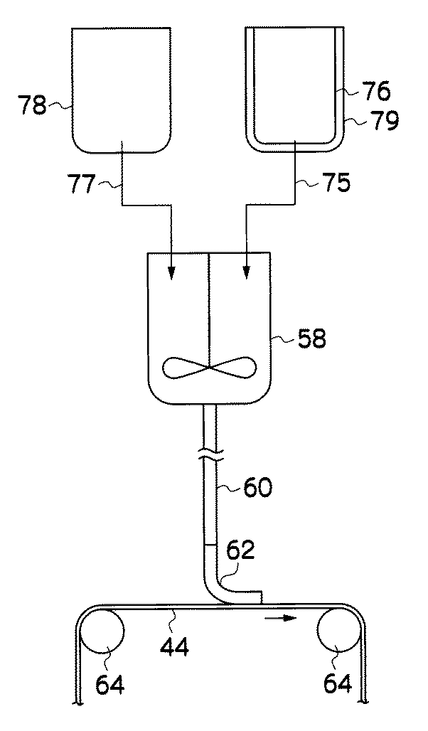
表1から分かるように、乾燥用の温風をHEPAフィルタに通過させなかった比較例1、2は、微孔性膜に欠点が発生し、且つ、微孔性膜の端部にカビ菌が発生した。特に無接触搬送を行わずにフラットローラで搬送した比較例2では、微孔性膜の欠点数、カビ菌の発生数ともに多くなった。これに対して、乾燥用の温風をHEPAフィルタに通過させた実施例1、2は、微孔性膜の欠点、カビ菌とも発生を防止することができた。 As can be seen from Table 1, in Comparative Examples 1 and 2 in which the hot air for drying was not passed through the HEPA filter, defects occurred in the microporous membrane, and fungi were present at the end of the microporous membrane. Occurred. Particularly, in Comparative Example 2 in which conveyance was performed by a flat roller without performing non-contact conveyance, both the number of defects of the microporous membrane and the number of molds were increased. On the other hand, Examples 1 and 2 in which the warm air for drying was passed through the HEPA filter could prevent the defects of the microporous membrane and fungi.
10…微孔性膜の製造装置、12…溶解タンク、18…ダイ、20…帯状支持体、22…ドラム、26…凝固槽、36…調湿ゾーン、44…微孔性膜、48…水洗槽、50…ターンバー、52…乾燥室、56…濡れ剤の塗布室、58…調製タンク、66…濡れ剤の乾燥室、68…ドラム、80…濾過装置、86…フィルタユニット
DESCRIPTION OF
Claims (3)
前記濡れ剤乾燥工程は、HEPAフィルタを通過したエアを前記微孔性膜の表面に吹きつけることを特徴とする微孔性膜の製造方法。 In a method for producing a microporous membrane, comprising a wetting agent application step of applying a wetting agent to the surface of the microporous membrane, and a wetting agent drying step of drying the wetting agent applied in the wetting agent application step.
In the method of manufacturing a microporous membrane, the wetting agent drying step blows air that has passed through a HEPA filter onto the surface of the microporous membrane.
前記濡れ剤乾燥装置は、
その外面に複数の噴射口を有し、該噴射口からエアを噴射することによって前記微孔性膜を前記外面から浮上させて支持する無接触搬送ローラと、
前記無接触搬送ローラにエア供給ラインを介して接続され、前記噴射口から噴射されるエアを前記無接触搬送ローラに送気する送気手段と、
前記エア供給ライン上に配設されたHEPAフィルタと、
を備えたことを特徴とする微孔性膜の製造装置。 In a microporous membrane manufacturing apparatus, comprising: a wetting agent application device that applies a wetting agent to the surface of the microporous membrane; and a wetting agent drying device that dries the wetting agent applied by the wetting agent application device.
The wetting agent drying device
A non-contact conveying roller that has a plurality of ejection ports on its outer surface and supports the microporous film by floating from the outer surface by ejecting air from the ejection ports;
An air supply means connected to the non-contact conveying roller via an air supply line, and for supplying air injected from the injection port to the non-contact conveying roller;
A HEPA filter disposed on the air supply line;
An apparatus for producing a microporous membrane, comprising:
Priority Applications (1)
| Application Number | Priority Date | Filing Date | Title |
|---|---|---|---|
| JP2007073421A JP2007289932A (en) | 2006-03-27 | 2007-03-20 | Microporous membrane manufacturing method and device used for the same |
Applications Claiming Priority (2)
| Application Number | Priority Date | Filing Date | Title |
|---|---|---|---|
| JP2006086468 | 2006-03-27 | ||
| JP2007073421A JP2007289932A (en) | 2006-03-27 | 2007-03-20 | Microporous membrane manufacturing method and device used for the same |
Publications (1)
| Publication Number | Publication Date |
|---|---|
| JP2007289932A true JP2007289932A (en) | 2007-11-08 |
Family
ID=38761065
Family Applications (1)
| Application Number | Title | Priority Date | Filing Date |
|---|---|---|---|
| JP2007073421A Pending JP2007289932A (en) | 2006-03-27 | 2007-03-20 | Microporous membrane manufacturing method and device used for the same |
Country Status (1)
| Country | Link |
|---|---|
| JP (1) | JP2007289932A (en) |
-
2007
- 2007-03-20 JP JP2007073421A patent/JP2007289932A/en active Pending
Similar Documents
| Publication | Publication Date | Title |
|---|---|---|
| US4933081A (en) | Asymmetric micro-porous membrane containing a layer of minimum size pores below the surface thereof | |
| JP4809346B2 (en) | Web-reinforced separation membrane and continuous manufacturing method thereof | |
| US4840733A (en) | Fine porous membrane and process for producing the same | |
| KR101523449B1 (en) | Method for manufacturing sheet-shaped separation membrane | |
| JP2007289937A (en) | Method and apparatus for manufacturing microporous membrane | |
| US20120000846A1 (en) | Polymer coated hydrolyzed membrane | |
| US20210260538A1 (en) | Method for manufacturing porous membrane and porous membrane | |
| JP2012139619A (en) | Polyvinylidene fluoride porous flat membrane and method for manufacturing the same | |
| JP4629603B2 (en) | Separation membrane and composite membrane comprising the separation membrane, humidifying element, dehumidifying element, humidifier, dehumidifier, and humidity control system | |
| JP6097151B2 (en) | Method for producing gas separation membrane | |
| JP2015180495A (en) | Composite separation membrane, and composite separation membrane element | |
| JPS63139930A (en) | Production of microporous membrane | |
| JP4084103B2 (en) | Method and apparatus for producing porous hollow fiber membrane | |
| JP2007289935A (en) | Microporous membrane manufacturing method and apparatus used for the same | |
| JP2007289932A (en) | Microporous membrane manufacturing method and device used for the same | |
| JP2007289936A (en) | Microporous membrane manufacturing method and apparatus used for the same | |
| JP3681219B2 (en) | Polysulfone porous separation membrane | |
| JP2530133B2 (en) | Microporous membrane | |
| JP2007289938A (en) | Method and apparatus for manufacturing microporous membrane | |
| JP2015112502A (en) | Laminate and gas separation membrane, and method of manufacturing the laminate | |
| JP2000042385A (en) | Production of sheet type separation membrane | |
| JP2014521493A (en) | Gas separation membrane | |
| WO2023276614A1 (en) | Forward osmosis membrane and forward osmosis membrane module including same | |
| EP2889076B1 (en) | Membrane with surface channels | |
| JP2004025066A (en) | Method for manufacturing porous hollow fiber membrane |