JP2007285708A - Quality control method for liquid for supporting analysis in autoanalyzer, and the autoanalyzer - Google Patents
Quality control method for liquid for supporting analysis in autoanalyzer, and the autoanalyzer Download PDFInfo
- Publication number
- JP2007285708A JP2007285708A JP2006109719A JP2006109719A JP2007285708A JP 2007285708 A JP2007285708 A JP 2007285708A JP 2006109719 A JP2006109719 A JP 2006109719A JP 2006109719 A JP2006109719 A JP 2006109719A JP 2007285708 A JP2007285708 A JP 2007285708A
- Authority
- JP
- Japan
- Prior art keywords
- liquid
- analysis
- dispensing
- sample
- analysis support
- Prior art date
- Legal status (The legal status is an assumption and is not a legal conclusion. Google has not performed a legal analysis and makes no representation as to the accuracy of the status listed.)
- Granted
Links
Images


Classifications
-
- G—PHYSICS
- G01—MEASURING; TESTING
- G01N—INVESTIGATING OR ANALYSING MATERIALS BY DETERMINING THEIR CHEMICAL OR PHYSICAL PROPERTIES
- G01N35/00—Automatic analysis not limited to methods or materials provided for in any single one of groups G01N1/00 - G01N33/00; Handling materials therefor
- G01N35/00584—Control arrangements for automatic analysers
- G01N35/00594—Quality control, including calibration or testing of components of the analyser
- G01N35/00613—Quality control
- G01N35/00663—Quality control of consumables
-
- Y—GENERAL TAGGING OF NEW TECHNOLOGICAL DEVELOPMENTS; GENERAL TAGGING OF CROSS-SECTIONAL TECHNOLOGIES SPANNING OVER SEVERAL SECTIONS OF THE IPC; TECHNICAL SUBJECTS COVERED BY FORMER USPC CROSS-REFERENCE ART COLLECTIONS [XRACs] AND DIGESTS
- Y10—TECHNICAL SUBJECTS COVERED BY FORMER USPC
- Y10T—TECHNICAL SUBJECTS COVERED BY FORMER US CLASSIFICATION
- Y10T436/00—Chemistry: analytical and immunological testing
- Y10T436/11—Automated chemical analysis
- Y10T436/115831—Condition or time responsive
Abstract
Description
本発明は、試料と試薬とを反応させることによって前記試料の分析を行う自動分析装置において、純水を含む液体であって前記試料の分析を支援する液体である分析支援用液体の品質を管理する自動分析装置の分析支援用液体の品質管理方法および自動分析装置に関する。 The present invention manages the quality of an analysis support liquid that is a liquid containing pure water and supporting the analysis of the sample in an automatic analyzer that analyzes the sample by reacting the sample with a reagent. The present invention relates to a liquid quality control method and an automatic analyzer for analysis support of an automatic analyzer.
試料と試薬とを反応させることによってその試料の分析を行う自動分析装置では、試料や試薬を分注する分注機構における圧力伝達用媒体、反応容器の洗浄液、希釈液等の分析支援用液体の少なくとも一部として、イオン交換水や蒸留水などの純水が広く使用されている(例えば、特許文献1を参照)。このような純水は、純水装置から配管系を経由して自動分析装置へ供給され、自動分析装置内の純水タンクに貯留される。 In an automatic analyzer that analyzes a sample by reacting the sample with a reagent, an analysis support liquid such as a pressure transmission medium, a reaction container cleaning liquid, a dilution liquid, etc. in a dispensing mechanism for dispensing the sample or reagent is used. As at least a part, pure water such as ion-exchanged water or distilled water is widely used (see, for example, Patent Document 1). Such pure water is supplied from the pure water device to the automatic analyzer via the piping system and stored in a pure water tank in the automatic analyzer.
分析に不可欠な純水の品質管理は、自動分析装置の信頼性を高める上で重要である。このため、従来は、純水装置の出口付近に水質計を設けておき、この水質計を通過した純水の比抵抗値(または電気伝導率)を測定することによって純水の品質管理を行っていた。 Quality control of pure water, which is essential for analysis, is important for improving the reliability of automatic analyzers. For this reason, conventionally, a water quality meter is provided near the outlet of the pure water device, and quality control of pure water is performed by measuring the specific resistance value (or electrical conductivity) of the pure water that has passed through the water quality meter. It was.
自動分析装置を長期間にわたって使用する場合、その自動分析装置内の純水タンクや配管系に微生物や細菌などが侵入または発生することによって純水が汚染されることがある。また、自動分析装置の長期間にわたる使用によって配管系の内部にヌメリや黒ずみが生じ、配管系の素材の一部をなす金属部品から金属イオンが溶出したり、その金属部品に錆びが発生したりすることによって純水が汚染されることもある。 When an automatic analyzer is used for a long period of time, pure water may be contaminated by intrusion or generation of microorganisms or bacteria into a pure water tank or piping system in the automatic analyzer. In addition, long-term use of the automatic analyzer causes slime and darkening inside the piping system, and metal ions are eluted from metal parts that form part of the piping system, and rusting occurs on the metal parts. Doing so may contaminate pure water.
上記の如く汚染された純水には、試料と試薬との反応を阻害または亢進させる成分が含まれる場合もあるため、そのような成分の量が多くなるにつれて、分析への影響が無視できなくなる可能性がある。実際、血液の生化学検査においては、錆びに含まれる金属イオン(鉄イオン、銅イオン等)が血液中の金属イオンに影響を及ぼす場合があることが知られている。また、血液の免疫検査においては、微生物が産生する酵素が血液中の酵素に影響を及ぼす場合があることが知られている。 Since pure water contaminated as described above may contain components that inhibit or enhance the reaction between the sample and the reagent, the influence on the analysis cannot be ignored as the amount of such components increases. there is a possibility. In fact, in blood biochemical tests, it is known that metal ions (iron ions, copper ions, etc.) contained in rust may affect metal ions in blood. In blood immunoassays, it is known that enzymes produced by microorganisms may affect enzymes in blood.
このことからも明らかなように、自動分析装置内における純水の汚染を検出することは、分析の精度を維持する上で不可欠である。しかしながら、上述した従来技術では、自動分析装置に供給された後の純水の品質を判定しないため、純水が自動分析装置内において分析に影響を及ぼす程度にまで汚染されてしまった場合には、分析の精度を適正に維持することができなくなる恐れがあった。 As is clear from this, it is indispensable to detect the contamination of pure water in the automatic analyzer in order to maintain the accuracy of the analysis. However, in the above-described prior art, since the quality of the pure water after being supplied to the automatic analyzer is not judged, when the pure water is contaminated to the extent that it affects the analysis in the automatic analyzer. There is a risk that the accuracy of the analysis cannot be properly maintained.
本発明は、上記に鑑みてなされたものであって、自動分析装置における分析を支援する分析支援用液体が自動分析装置に供給された後の品質を適確に判定し、分析の精度を適正に維持することができる自動分析装置の分析支援用液体の品質管理方法および自動分析装置を提供することを目的とする。 The present invention has been made in view of the above, and accurately determines the quality after an analysis support liquid that supports analysis in an automatic analyzer is supplied to the automatic analyzer, and the accuracy of analysis is appropriate. An object of the present invention is to provide a liquid quality control method and an automatic analyzer that can be maintained in an automatic analyzer.
上述した課題を解決し、目的を達成するために、請求項1記載の発明は、純水を含む液体であって試料の分析を支援する液体である分析支援用液体を圧力伝達用媒体として前記試料を分注する試料分注手段と、前記分析支援用液体を圧力伝達用媒体として試薬を分注する試薬分注手段と、前記分析支援用液体を洗浄液として前記試料と前記試薬とを混合して反応させる反応容器を洗浄する洗浄手段と、前記分析支援用液体を含む希釈液を分注する希釈液分注手段とを備え、前記試料の分析を行う自動分析装置において、前記分析支援用液体の品質を管理する自動分析装置の分析支援用液体の品質管理方法であって、前記分析支援用液体を、前記試料分注手段、前記試薬分注手段、前記洗浄手段または前記希釈液分注手段によって前記反応容器に分注する分注ステップと、前記分注ステップで分注した前記分析支援用液体を含む前記反応容器内の液体に対する光学的な測定を行う測光ステップと、前記測光ステップで測定した結果を用いて前記分析支援用液体の分析データを生成するデータ生成ステップと、前記データ生成ステップで生成した分析データを基準データと比較することによって前記分析支援用液体の品質を判定する品質判定ステップと、を有することを特徴とする。 In order to solve the above-described problems and achieve the object, the invention according to claim 1 is characterized in that the analysis support liquid, which is a liquid containing pure water and supports the analysis of the sample, is used as the pressure transmission medium. Sample dispensing means for dispensing a sample, reagent dispensing means for dispensing a reagent using the analysis support liquid as a pressure transmission medium, and mixing the sample and the reagent using the analysis support liquid as a cleaning liquid In the automatic analyzer for analyzing the sample, comprising: a cleaning means for cleaning the reaction vessel to be reacted; and a diluent dispensing means for dispensing a diluent containing the analysis support liquid; An analysis support liquid quality control method for an automatic analyzer that manages the quality of the sample, wherein the analysis support liquid is dispensed with the sample dispensing means, the reagent dispensing means, the washing means, or the diluting liquid dispensing means. By the reaction vessel A dispensing step for dispensing, a photometric step for optically measuring the liquid in the reaction vessel containing the analysis support liquid dispensed in the dispensing step, and a result measured in the photometric step A data generation step of generating analysis data of the analysis support liquid, and a quality determination step of determining the quality of the analysis support liquid by comparing the analysis data generated in the data generation step with reference data It is characterized by that.
この発明における「純水」とは、イオン交換水、逆浸透膜投下水、蒸留水、精製水など、自動分析装置の分析支援用液体として使用可能なものを指す。また、この発明における「液体」には、微量の固体成分を含有する液体も含まれる。 The “pure water” in the present invention refers to water that can be used as an analysis support liquid of an automatic analyzer such as ion exchange water, reverse osmosis membrane dropping water, distilled water, and purified water. In addition, the “liquid” in the present invention includes a liquid containing a trace amount of a solid component.
請求項2記載の発明は、請求項1記載の発明において、前記測光ステップで光学的な測定を受ける前記反応容器内の液体は、前記分析支援用液体と検査項目に応じた試薬との混合液であることを特徴とする。 According to a second aspect of the present invention, in the first aspect of the present invention, the liquid in the reaction vessel that is optically measured in the photometric step is a mixed liquid of the analysis support liquid and a reagent corresponding to a test item. It is characterized by being.
請求項3記載の発明は、請求項2記載の発明において、前記品質判定ステップで前記分析支援用液体の品質に異常があると判定した場合、前記試料に対して行う分析のうち少なくとも前記異常に関連した検査項目の分析を中止する制御を行う制御ステップをさらに有することを特徴とする。 According to a third aspect of the present invention, in the second aspect of the present invention, when it is determined in the quality determination step that the quality of the analysis support liquid is abnormal, at least the abnormality in the analysis performed on the sample It further has a control step for performing control to stop the analysis of the related inspection item.
請求項4記載の発明は、請求項1〜3のいずれか一項記載の発明において、前記品質判定ステップで判定した結果を含む情報を出力する出力ステップをさらに有することを特徴とする。 According to a fourth aspect of the present invention, there is provided the method according to any one of the first to third aspects, further comprising an output step of outputting information including a result determined in the quality determination step.
請求項5記載の発明に係る自動分析装置は、純水を含む液体であって試料の分析を支援する液体である分析支援用液体を圧力伝達用媒体として前記試料を分注する試料分注手段と、前記分析支援用液体を圧力伝達用媒体として試薬を分注する試薬分注手段と、前記分析支援用液体を洗浄液として前記試料と前記試薬とを混合して反応させる反応容器を洗浄する洗浄手段と、前記分析支援用液体を含む希釈液を分注する希釈液分注手段と、前記試料分注手段、前記試薬分注手段、前記洗浄手段または前記希釈液分注手段によって前記反応容器に分注された前記分析支援用液体を含む液体に対する光学的な測定を行う測光手段と、前記測光手段で測定した結果を用いて前記分析支援用液体の分析データを生成するデータ生成手段と、前記データ生成手段で生成した分析データを基準データと比較することによって前記分析支援用液体の品質を判定する品質判定手段と、を備えたことを特徴とする。 According to a fifth aspect of the present invention, there is provided an automatic analyzer that dispenses the sample using an analysis support liquid that is a liquid containing pure water and supports the analysis of the sample as a pressure transmission medium. A reagent dispensing unit that dispenses a reagent using the analysis support liquid as a pressure transmission medium, and a cleaning that cleans a reaction container in which the sample and the reagent are mixed and reacted using the analysis support liquid as a cleaning liquid Means, a diluent dispensing means for dispensing a diluent containing the analysis support liquid, and the sample dispensing means, the reagent dispensing means, the washing means, or the diluent dispensing means. Photometric means for performing optical measurement on the dispensed liquid containing the analysis support liquid, data generation means for generating analysis data of the analysis support liquid using a result measured by the photometry means, and Data raw Characterized in that and a determining quality judgment means the quality of the liquid for the analysis support by comparing the analysis data generated by the means and the reference data.
この発明における「純水」とは、イオン交換水、逆浸透膜投下水、蒸留水、精製水など、自動分析装置の分析支援用液体として使用可能なものを指す。また、この発明における「液体」には、微量の固体成分を含有する液体も含まれる。 The “pure water” in the present invention refers to water that can be used as an analysis support liquid of an automatic analyzer such as ion exchange water, reverse osmosis membrane dropping water, distilled water, and purified water. In addition, the “liquid” in the present invention includes a liquid containing a trace amount of a solid component.
請求項6記載の発明は、請求項5記載の発明において、前記測光手段によって光学的な測定を受ける前記反応容器内の液体は、前記分析支援用液体と検査項目に応じた試薬との混合液であることを特徴とする。 According to a sixth aspect of the present invention, in the fifth aspect of the present invention, the liquid in the reaction vessel which is optically measured by the photometric means is a mixed liquid of the analysis support liquid and a reagent corresponding to a test item. It is characterized by being.
請求項7記載の発明は、請求項6記載の発明において、前記品質判定手段で前記分析支援用液体の品質に異常があると判定した場合、前記試料に対して行う分析のうち少なくとも前記異常に関連した検査項目の分析を中止する制御を行う制御手段をさらに備えたこと特徴とする。 According to a seventh aspect of the present invention, in the sixth aspect of the invention, when the quality determination means determines that the quality of the analysis support liquid is abnormal, at least the abnormality among the analyzes performed on the sample is performed. Control means for performing control to stop analysis of related inspection items is further provided.
請求項8記載の発明は、請求項5〜7のいずれか一項記載の発明において、前記品質判定手段で判定した結果を含む情報を出力する出力手段をさらに備えたことを特徴とする。 The invention according to claim 8 is the invention according to any one of claims 5 to 7, further comprising output means for outputting information including a result determined by the quality determination means.
本発明によれば、試料を分注する試料分注手段、試薬を分注する試薬分注手段、反応容器を洗浄する洗浄手段または希釈液を分注する希釈液分注手段によって試料の分析を支援する分析支援用液体を反応容器に分注し、この分注した分析支援用液体を含む反応容器内の液体に対する光学的な測定を行い、測定した結果を用いて分析支援用液体の分析データを生成し、生成した分析データを基準データと比較することによって分析支援用液体の品質を判定することにより、自動分析装置における分析を支援する分析支援用液体が自動分析装置に供給された後の品質を適確に判定し、分析の精度を適正に維持することが可能となる。 According to the present invention, the sample is analyzed by the sample dispensing means for dispensing the sample, the reagent dispensing means for dispensing the reagent, the washing means for washing the reaction container, or the diluent dispensing means for dispensing the diluent. Dispensing the supporting analysis support liquid into the reaction container, optically measure the liquid in the reaction container containing the dispensed analysis support liquid, and use the measurement results to analyze the analysis support liquid analysis data. And analyzing the generated analysis data by comparing the generated analysis data with reference data to determine the quality of the analysis support liquid, so that the analysis support liquid that supports the analysis in the automatic analyzer is supplied to the automatic analyzer. It is possible to accurately determine the quality and maintain the accuracy of the analysis appropriately.
以下、添付図面を参照して本発明を実施するための最良の形態(以後、「実施の形態」と称する)を説明する。図1は、本発明の一実施の形態に係る自動分析装置要部の構成を模式的に示す図である。同図に示す自動分析装置1は、試料と試薬とを所定の容器にそれぞれ分注し、その容器内の液体に対して光学的な測定を行う測定機構101と、この測定機構101を含む自動分析装置1の制御を行うとともに測定機構101における測定結果の分析を行う制御分析機構102とを有し、これら二つの機構が連携することによって複数の検体の生化学的な分析を自動的かつ連続的に行う装置である。なお、ここでいう「液体」には、微量の固体成分を含有する液体も含まれる。
The best mode for carrying out the present invention (hereinafter referred to as “embodiment”) will be described below with reference to the accompanying drawings. FIG. 1 is a diagram schematically showing a configuration of a main part of an automatic analyzer according to an embodiment of the present invention. An automatic analyzer 1 shown in FIG. 1 dispenses a sample and a reagent into predetermined containers, and performs a
最初に、自動分析装置1の測定機構101について説明する。測定機構101は、主として一般検体を収容する検体容器111が搭載された複数のラック112を収納して順次移送する検体移送部11と、一般検体以外の各種検体(検量線作成用のスタンダード検体、精度管理検体、緊急検体、STAT検体、再検査用検体等)を収容する検体容器121を保持する検体容器保持部12と、試薬容器131を保持する試薬容器保持部13と、試料(検体)と試薬とを反応させる容器である反応容器141を保持する反応容器保持部14と、反応容器141の内部に収容された液体を攪拌する攪拌部15と、反応容器141内を通過した光の波長成分ごとの強度等を測定する測光部16と、を備える。
First, the
また、測定機構101は、検体移送部11上の検体容器111や検体容器保持部12上の検体容器121に収容された検体等の試料を反応容器141に分注する試料分注部17と、試薬容器保持部13上の試薬容器131に収容された試薬を反応容器141に分注する試薬分注部18と、反応容器141の洗浄を行う洗浄部19と、反応容器141内の液体を希釈する希釈液を分注する希釈液分注部20と、を備える。
The
検体容器111および121には、内部に収容する検体を識別する識別情報をバーコードまたは2次元コード等の情報コードにコード化して記録した情報コード記録媒体がそれぞれ貼付されている(図示せず)。同様に、試薬容器131にも、内部に収容する試薬を識別する識別情報を情報コードにコード化して記録した情報コード記録媒体が貼付されている(図示せず)。このため、測定機構101には、検体容器111に貼付された情報コードを読み取る情報コード読取部CR1、検体容器121に貼付された情報コードを読み取る情報コード読取部CR2、および試薬容器131に貼付された情報コードを読み取る情報コード読取部CR3が設けられている。
Each of the
検体容器保持部12、試薬容器保持部13、および反応容器保持部14は、検体容器121、試薬容器131および反応容器141をそれぞれ収容保持するホイールと、このホイールの底面中心に取り付けられ、その中心を通る鉛直線を回転軸としてホイールを回転させる駆動手段とを有する(図示せず)。
The sample
各容器保持部の内部は一定の温度に保たれている。例えば、試薬容器保持部13内は、試薬の劣化や変性を抑制するために室温よりも低温に設定される。また、反応容器保持部14内は、人間の体温と同程度の温度に設定される。
The inside of each container holding part is kept at a constant temperature. For example, the inside of the reagent
測光部16は、白色光を照射する光源と、反応容器141を透過してきた白色光を分光する分光光学系と、分光光学系で分光した光を成分ごとに受光して電気信号に変換する受光素子とを有する。
The
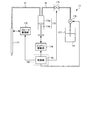
図2は、試料分注部17の構成を模式的に示す図である。同図に示す試料分注部17は、試料の吸引および吐出を行うために先細の先端を有する中空のプローブ171と、このプローブ171の鉛直方向の昇降および水平方向の回転を行うアーム等を有するプローブ駆動部172と、プローブ171に圧力を伝達する圧力伝達用媒体としてプローブ171による試料の吸引、吐出を支援する洗浄液Lqの流路をなすチューブ31(配管系の一部)と、試料を吸引または吐出するためにプローブ171に加えられる圧力であってチューブ31内の洗浄液Lqを介して加えられる圧力を発生するシリンジ173と、を備える。
FIG. 2 is a diagram schematically showing the configuration of the
シリンジ173はシリンダ173aとピストン173bとを有し、ピストン駆動部174によってピストン173bがシリンダ173aの内部を摺動しながら移動することにより、シリンダ173a内部の洗浄液Lqに対して加える圧力を変化させる。
The
シリンジ173には、洗浄液Lqの別の流路であって配管系の一部をなすチューブ32が接続されている。このチューブ32には、洗浄液Lqの流れを制御する電磁弁175、および洗浄液Lqの吸排動作が行われるポンプ176が順次介在している。チューブ32のシリンジ173に接続される側と異なる端部は、洗浄液Lqを収容する洗浄液タンク177内に到達している。
The
分析支援用液体である洗浄液Lqとしては、イオン交換水、逆浸透膜投下水、蒸留水、または精製水などの純水が適用される。このような純水は、自動分析装置1の外部に設けられる純水装置によって生成され、所定の配管系を経由して洗浄液タンク177に供給されている(純水装置および配管系は図示せず)。
Pure water such as ion exchange water, reverse osmosis membrane dropping water, distilled water, or purified water is applied as the cleaning liquid Lq that is an analysis support liquid. Such pure water is generated by a pure water device provided outside the automatic analyzer 1, and is supplied to the cleaning
以上の構成を有する試料分注部17におけるプローブ171の移動やプローブ171における検体の吸引および吐出を含む動作は、制御分析機構102が有する制御部26によって制御される。
The operation including the movement of the
試薬分注部18は、試料分注部17と同様の構成を有する。また、洗浄部19のうち洗浄液Lqを吐出する部分の構成も、試料分注部17の構成と同様である。さらに、希釈液分注部20も試料分注部17と同様の構成を有しており(ただし、この場合のプローブ駆動部は水平方向の回転機能を具備しなくてもよい)、洗浄液Lqを希釈液として反応容器141への洗浄液Lqの吐出を行う。本実施の形態では、試薬分注部18、洗浄部19、および希釈液分注部20で使用する洗浄液Lqは、全て洗浄液タンク177から供給される。
The
なお、生化学的な分析を行う際には一つの検体に対して2種類の試薬を用いることが多いため、第1試薬用の試薬容器保持部13と第2試薬用の試薬容器保持部13とを別個に設けてもよい。この場合には、個々の試薬容器保持部13に対応した試薬分注部18を2個設ければよい。より一般には、試薬容器保持部13や試薬分注部18を複数個設けることもできる。
Note that when performing biochemical analysis, two types of reagents are often used for one specimen, so that the reagent
また、検体、試薬または希釈液の分注後の適当なタイミングで複数の反応容器141内の液体の攪拌を同時に行うために、攪拌部15を複数個設けてもよい。
In order to simultaneously stir the liquid in the plurality of
ところで、図1では、測定機構101の主要な構成要素を模式的に示すことを主眼としているため、構成要素間の位置関係は必ずしも正確ではない。正確な構成要素間の位置関係は、試薬容器保持部13の数や分注動作のインターバルにおける反応容器保持部14のホイールの回転態様などの各種条件に応じて定められるべき設計的事項である。
By the way, in FIG. 1, since the main purpose is to schematically show the main components of the
次に、引き続き図1を参照して、自動分析装置1の制御分析機構102について説明する。制御分析機構102は、検体の分析に必要な情報や自動分析装置1の動作を指示する動作指示信号などを含む情報の入力を受ける入力部21と、検体の分析に関する情報を出力する出力部22と、測定機構101における測定結果に基づいて検体の分析データを生成するデータ生成部23と、データ生成部23で生成した分析データを用いて分析支援用液体の品質を判定する品質判定部24と、検体の分析に関する情報や自動分析装置1に関する情報を含む各種情報を記憶する記憶部25と、制御分析機構102内の各機能または各手段の制御を行うとともに測定機構101の駆動制御を行う制御部26と、を備える。
Next, the
入力部21は、キーボードやマウスを有する。また、入力部21として、トラックボール、トラックパッドなどのポインティングデバイスや、音声入力用のマイクロフォン等のユーザインターフェースをさらに具備してもよい。
The
出力部22は、各種情報を表示する液晶、プラズマ、有機EL、CRT等のディスプレイ装置を有する。また、出力部22として、音声出力用のスピーカや、紙などに情報を印刷して出力するプリンタを具備させてもよい。
The
データ生成部23は、測定機構101の測光部16から受信した測定結果の分析演算を行う。この分析演算では、測光部16から送られてくる測定結果に基づいて反応容器141内の液体の吸光度を算出したり、吸光度の算出結果と検量線や分析パラメータ等の各種情報とを用いて反応容器141内の液体の成分を定量的に求める成分量算出処理等を行ったりすることにより、検体ごとの分析データを生成する。このようにして生成された分析データは、出力部22から出力される一方、記憶部25に書き込まれて記憶される。
The
品質判定部24は、データ生成部23で生成した分析データと記憶部25で記憶する基準データとを比較することによって洗浄液Lqの品質を判定する。
The
記憶部25は、さまざまな情報を磁気的に記憶するハードディスクと、自動分析装置1が処理を実行する際にその処理に係るプログラムをハードディスクからロードして電気的に記録するメモリとを用いて実現され、分析項目、検体情報、試薬の種類、検体や試薬の分注量、試料や試薬の有効期限、分析に使用する検量線に関する情報、検量線の有効期限、各分析項目の参照値や許容値などの分析に必要なパラメータ、データ生成部23で生成した分析データなどを記憶、管理する。
The
記憶部25が記憶するプログラムには、本実施の形態に係る自動分析装置の分析支援用液体の品質管理方法(後述)を自動分析装置1に実行させるプログラムも含まれる。また、記憶部25は、フレキシブルディスク、CD−ROM、DVD−ROM、フラッシュメモリ等のコンピュータ読み取り可能な記録媒体に記録された情報を読み取る補助記憶装置を具備してもよく、そのような記録媒体に対して前述したプログラムを記録しておくことも可能である。
The program stored in the
制御部26は、制御および演算機能を有するCPU(Central Processing Unit)等によって実現され、記憶部25で記憶されるプログラムを記憶部25から読み出すことによって自動分析装置1の各種動作の制御および演算を実行する。
The
以上の機能構成を有する制御分析機構102は、一または複数のコンピュータを用いて実現される。このうち、制御分析機構102が複数のコンピュータを用いて実現される場合には、制御分析機構102が有する各機能を異なるコンピュータに適宜分散し、コンピュータ同士を直接的に接続するか、または通信ネットワーク(インターネット、イントラネット、専用回線網、LAN、電話網、等)を介して相互に接続すればよい。
The
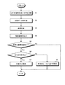
次に、本実施の形態に係る自動分析装置の分析支援用液体の品質管理方法の処理の概要を、図3に示すフローチャートを参照して説明する。なお、以下の説明においては、自動分析装置1が処理を実行するものとして説明を行うが、本実施の形態に係る自動分析装置の分析支援用液体の品質管理方法を実行する自動分析装置の構成は上述したものに限られるわけではない。 Next, the outline of the process of the quality control method for the analysis supporting liquid of the automatic analyzer according to the present embodiment will be described with reference to the flowchart shown in FIG. In the following description, the automatic analyzer 1 is described as executing processing, but the configuration of the automatic analyzer that executes the quality control method for the analysis support liquid of the automatic analyzer according to the present embodiment. Is not limited to those described above.
まず、分析支援用液体である洗浄液Lqを検体に見立てて測定を行う(ステップS1)。具体的には、洗浄液Lqと試薬とを反応容器141に分注し、この分注した後の反応容器141内の液体(洗浄液Lqと試薬との混合液)に対して測光部16が光学的な測定を行う。ここでの測光部16による測定は、反応容器保持部14を回転させている間に行われる。
First, measurement is performed with the cleaning liquid Lq, which is an analysis support liquid, taken as a sample (step S1). Specifically, the washing liquid Lq and the reagent are dispensed into the
このステップS1で分注する洗浄液Lqは、試料分注部17、試薬分注部18、洗浄部19、または希釈液分注部20のいずれかが有するプローブ内に充填されたものである。かかる洗浄液Lqを分注する際には、該当するプローブ内の洗浄液Lqを反応容器141に直接吐出するようにしてもよいし、該当するプローブ内の洗浄液Lqを空の検体容器121または反応容器141へいったん吐出した後、この吐出した洗浄液Lqを通常の検体と同様にプローブで所定量だけ吸引し、反応容器141へ吐出するようにしてもよい。
The cleaning liquid Lq to be dispensed in step S1 is filled in the probe included in any of the
ステップS1の処理は、通常の検体の分析動作と同様に、互いに異なる複数の検査項目に対して行うことが可能である。この場合の分注動作は検査項目によって異なり、例えば洗浄液Lqの分注に先立って試薬を分注する場合もあれば、2種類の試薬を分注する間に試料としての洗浄液Lqを分注する場合もある。また、洗浄液Lqのみを分注する場合もある。このため、分注および測光の各タイミングは、制御部26によって検査項目ごとに制御されている。
The processing in step S1 can be performed on a plurality of test items that are different from each other, as in the case of the normal sample analysis operation. The dispensing operation in this case varies depending on the inspection item. For example, the reagent may be dispensed prior to dispensing the washing liquid Lq, or the washing liquid Lq as a sample is dispensed between the two kinds of reagents. In some cases. Further, only the cleaning liquid Lq may be dispensed. For this reason, each timing of dispensing and photometry is controlled for each inspection item by the
その後、ステップS1で得た測定結果を用いることにより、データ生成部23が検査項目ごとの分析データを生成する(ステップS2)。このステップS2における分析データの生成処理は、通常の検体に対する分析データの生成処理と同様に行う。
Thereafter, by using the measurement result obtained in step S1, the
次に、品質判定部24が、ステップS3で生成した分析データを所定の基準データと比較することによって洗浄液Lqの品質を判定する(ステップS3)。その後、この判定結果を出力部22で出力する(ステップS4)。
Next, the
図4は、出力部22における洗浄液Lqの品質判定結果の表示出力例を示す図である。同図に示すテーブルTは、試料分注部17のプローブ171内に充填された洗浄液Lqに対して、基準データにおける正常範囲が互いに異なるA〜Eの5種類の検査項目について品質判定を行った場合の判定結果の表示出力例を示している。この場合、検査項目Cのみが正常範囲から外れている。したがって、検査項目CのみがNG(異常)であり、その他の検査項目A,B,DおよびEはOK(正常)と表示されている。
FIG. 4 is a diagram illustrating a display output example of the quality determination result of the cleaning liquid Lq in the
この後、ステップS3における品質判定において異常と判定された検査項目がなければ(ステップS5でNo)、一連の分析支援用液体の品質管理処理を終了する。他方、ステップS3における品質判定において、図4に示す検査項目Cのように異常と判定された検査項目がある場合(ステップS5でYes)には、続くステップS6に進む。 Thereafter, if there is no inspection item determined to be abnormal in the quality determination in Step S3 (No in Step S5), the series of analysis support liquid quality management processing is terminated. On the other hand, in the quality determination in step S3, when there is an inspection item determined to be abnormal like the inspection item C shown in FIG. 4 (Yes in step S5), the process proceeds to subsequent step S6.
ステップS6では、分析支援用液体の品質管理処理の後で行う通常の検体の分析を全ての検査項目に対して中止するか否かの判定を行う。通常の検体の分析を全ての検査項目に対して中止する場合(ステップS6でYes)には、制御部26が全ての項目の分析を中止する設定を行う(ステップS7)。これにより、自動分析装置1は動作が停止する。この場合には、自動分析装置1の動作が停止した後、ユーザが洗浄液Lqの交換や、洗浄液タンク177ならびにチューブ31および32の清掃等のメインテナンスを行うこととなる。
In step S6, a determination is made as to whether or not the analysis of the normal specimen performed after the quality control process of the analysis support liquid is to be stopped for all the test items. When the analysis of the normal specimen is stopped for all the test items (Yes in step S6), the
これに対して、通常の検体の分析を全ての検査項目に対して中止しない場合(ステップS6でNo)には、制御部26が所定のルールに基づいた設定を行う(ステップS8)。ここでの所定のルールとしては、例えば異常と判定された検査項目のみ通常の検体の分析を中止するようにすることができる。また、異常と判定された検査項目の数または種類に応じて、以後に行うべき分析動作を設定するようにしてもよい。
On the other hand, when the analysis of the normal specimen is not stopped for all the test items (No in step S6), the
ところで、以上説明した自動分析装置の分析支援用液体の品質管理方法を、自動分析装置1に電源を入れてスタンバイ状態になったときに自動的に実行するような設定としておけば、定期的に分析支援用液体の品質管理を行うことができるのでより好ましい。 By the way, if the above-described quality control method for the analysis support liquid of the automatic analyzer is set so as to be automatically executed when the automatic analyzer 1 is turned on and enters a standby state, the automatic analyzer 1 is periodically set. This is more preferable because quality control of the analysis support liquid can be performed.
また、上述した自動分析装置の分析支援用液体の品質管理方法を、通常の検体の分析を所定回数または所定時間行うたびに定期的に実行するような設定としておいてもよいし、ユーザが入力部21から操作信号を入力することによって随時実行することが可能な設定としておいてもよい。
In addition, the above-described quality control method for the analysis support liquid of the automatic analyzer may be set so that the analysis of the normal sample is performed periodically every predetermined number of times or for a predetermined time, or input by the user A setting that can be executed at any time by inputting an operation signal from the
なお、ステップS3における品質判定の結果、異常と判定された検査項目がある場合(ステップS5でYes)、出力部22がその後の自動分析装置1の動作の選択をユーザに促す内容を含む情報を表示出力するようにしてもよい。この場合、自動分析装置1は、入力部21からユーザによって入力された内容に応じた動作を行うこととなる。
If there is an inspection item determined to be abnormal as a result of the quality determination in step S3 (Yes in step S5), the
このように、分析支援用液体である洗浄液Lqの品質に異常が判明した場合、自動分析装置1が取り得る動作制御パターンを複数設けておくことにより、分析データの信頼性を確保した上で、分析の効率をも考慮した自動分析装置1の運用を実現することが可能となる。 As described above, when an abnormality is found in the quality of the cleaning liquid Lq, which is an analysis support liquid, by providing a plurality of operation control patterns that can be taken by the automatic analyzer 1, by ensuring the reliability of the analysis data, It is possible to realize the operation of the automatic analyzer 1 in consideration of the analysis efficiency.
以上説明した本発明の一実施の形態によれば、試料を分注する試料分注手段、試薬を分注する試薬分注手段、反応容器を洗浄する洗浄手段または希釈液を分注する希釈液分注手段によって試料の分析を支援する分析支援用液体を反応容器に分注し、この分注した分析支援用液体を含む反応容器内の液体に対する光学的な測定を行い、測定した結果を用いて分析支援用液体の分析データを生成し、生成した分析データを基準データと比較することによって分析支援用液体の品質を判定することにより、自動分析装置における分析を支援する分析支援用液体が自動分析装置に供給された後の品質を適確に判定し、分析の精度を適正に維持することが可能となる。 According to the embodiment of the present invention described above, the sample dispensing means for dispensing the sample, the reagent dispensing means for dispensing the reagent, the cleaning means for washing the reaction container, or the diluent for dispensing the diluent. Dispensing the analysis support liquid that supports the analysis of the sample into the reaction container using the dispensing means, optically measure the liquid in the reaction container containing the dispensed analysis support liquid, and use the measurement results. The analysis support liquid is automatically generated by generating the analysis data of the analysis support liquid and comparing the generated analysis data with the reference data to determine the quality of the analysis support liquid. It is possible to accurately determine the quality after being supplied to the analyzer and maintain the accuracy of analysis appropriately.
また、本実施の形態によれば、自動分析装置で使用される分析支援用液体の使用直前の最終的な状態での品質が分析データに影響するか否かを分析データとして測定し、異常がある場合にはその異常に応じた動作制御および異常内容のユーザへの告知を行うことにより、分析支援用液体の品質に異常がある状態を放置したまま分析を実行することを防止するとともに、分析データに異常が発生するのを未然に防止することができる。この結果、従来のように、分析データに異常が発生した後、その原因が分析支援用液体の劣化にあることを特定するまでに費やされる労力と時間の無駄をなくすことができ、より効率的な分析を実現することができる。 Further, according to the present embodiment, whether or not the quality in the final state immediately before use of the analysis support liquid used in the automatic analyzer affects the analysis data is measured as analysis data. In some cases, by controlling the operation according to the abnormality and notifying the user of the contents of the abnormality, it is possible to prevent the analysis from being performed while leaving the state where the quality of the liquid for analysis support is abnormal, and to analyze the analysis. It is possible to prevent data from being abnormal. As a result, after an abnormality has occurred in the analysis data as in the past, it is possible to eliminate the waste of labor and time required to determine that the cause is the deterioration of the analysis support liquid, which is more efficient. Analysis can be realized.
さらに、本実施の形態によれば、分析支援用液体に対する測定結果が分析データとして得られるため、通常の検体の分析への影響度を明確に判定することが可能となる。 Furthermore, according to the present embodiment, since the measurement result for the analysis support liquid is obtained as analysis data, it is possible to clearly determine the degree of influence on the analysis of a normal sample.
加えて、本実施の形態によれば、従来の自動分析装置に対して新たな構成要素を付加する必要がなく、品質管理に関わる測定自体も通常の検体の分析動作と同じなので、自動分析装置内の分析支援用液体の品質を容易に管理することができる。 In addition, according to the present embodiment, there is no need to add a new component to the conventional automatic analyzer, and the measurement itself related to quality control is the same as a normal sample analysis operation. The quality of the analysis support liquid can be easily managed.
ここまで、本発明を実施するための最良の形態を詳述してきたが、本発明は上述した一実施の形態によってのみ限定されるべきものではない。 The best mode for carrying out the present invention has been described in detail so far, but the present invention should not be limited only by the above-described embodiment.
本発明は、検体の成分を免疫学的に分析する自動分析装置に対しても適用可能である。例えば、抗原抗体反応に基づく不均一系反応を用いた検体の免疫学的な分析を行う際には、B/F洗浄などを行う生理食塩水等のバッファ液を使用する。このため、不均一系反応を用いた免疫分析用の自動分析装置に対して本発明を適用する場合、バッファ液を生成する前の純水を分析支援用液体として品質管理処理を行ってもよいし、バッファ液自体を分析支援用液体として品質管理処理を行ってもよい。なお、この場合の自動分析装置は、B/F洗浄を行うB/F洗浄部、および測光部として発光物質の発光量をカウントする光電子増倍管が必要となる。これらの点を除く自動分析装置の構成は、上述した自動分析装置の構成とほぼ同様である。 The present invention can also be applied to an automatic analyzer that immunologically analyzes components of a specimen. For example, when performing an immunological analysis of a specimen using a heterogeneous reaction based on an antigen-antibody reaction, a buffer solution such as physiological saline for performing B / F washing or the like is used. For this reason, when the present invention is applied to an automatic analyzer for immunoassay using a heterogeneous reaction, quality control processing may be performed using pure water before generating a buffer solution as an analysis support liquid. Then, the quality control process may be performed using the buffer solution itself as the analysis support liquid. In this case, the automatic analyzer requires a B / F cleaning unit that performs B / F cleaning, and a photomultiplier tube that counts the light emission amount of the luminescent material as a photometry unit. Except for these points, the configuration of the automatic analyzer is almost the same as the configuration of the automatic analyzer described above.
以下、免疫分析を行う場合の一例として、アルカリフォスファターゼ(ALP)という酵素を標識物質として用いることによってHBsAgの感染症検査を行う場合を説明する。HBsAgの感染症検査では、陽性と陰性の判定境界値であるカットオフ値(基準データに含まれる)は3800カウントに設定される。バッファ液を生成する際に使用する純水にはALPが本来含まれていないため、ALPに発光試薬を加えた時の発光量を与えるカウント値は、正常な場合300カウント程度となる(ここでの数値は、HBsAgの感染症検査における一例を示したものに過ぎない)。 Hereinafter, as an example of performing an immunoassay, a case where an infectious disease test for HBsAg is performed by using an enzyme called alkaline phosphatase (ALP) as a labeling substance will be described. In the HBsAg infectious disease test, the cutoff value (included in the reference data), which is a positive / negative judgment boundary value, is set to 3800 counts. Since pure water used for producing the buffer solution does not originally contain ALP, the count value that gives the amount of luminescence when a luminescent reagent is added to ALP is about 300 counts when normal (here, Is merely an example of HBsAg infection test).
しかしながら、ALPは天然界にも多く存在しており、人の手などにも付着しやすい。このため、人の手などに付着したALPによって純水が汚染されてしまう可能性がある。その場合、汚染された純水に発光試薬を加えた後のカウント値は、数千カウント程度まで増加することもあり得る。したがって、天然界に存在するALPによって純水が汚染されると、分析データがカットオフ値を超え、本体は陰性である検体を陽性と誤判定してしまう恐れが生じる。 However, ALP is also abundant in the natural world and easily adheres to human hands. For this reason, pure water may be contaminated by ALP adhering to human hands. In that case, the count value after adding the luminescent reagent to the contaminated pure water may increase to about several thousand counts. Therefore, when pure water is contaminated by ALP existing in the natural world, there is a risk that the analysis data exceeds the cutoff value and the main body is erroneously determined as positive.
このように、免疫学的な分析では微量の成分を高感度に測定するため、たとえ外部からの汚染物質の量が微量であったとしても、測定値に与える影響は多大なものとなり、場合によっては誤判定してしまうレベルとなり得る。 Since immunological analysis measures a very small amount of components with high sensitivity, even if the amount of contaminants from the outside is very small, the effect on the measured value is significant. May be at a level that makes a false determination.
本実施の形態によれば、上述した免疫学的な分析のように高感度の測定が要求される場合であっても、純水等の分析支援用液体の品質異常を適確に検知することができるので、分析データの誤判定を未然に防止することが可能となり、分析の精度を適正に維持することができる。 According to the present embodiment, even when high-sensitivity measurement is required as in the above-described immunological analysis, it is possible to accurately detect an abnormality in the quality of a liquid for analysis support such as pure water. Therefore, it is possible to prevent erroneous determination of analysis data, and to maintain the accuracy of analysis appropriately.
以上の説明からも明らかなように、本発明は、ここでは記載していないさまざまな実施の形態等を含みうるものであり、特許請求の範囲により特定される技術的思想を逸脱しない範囲内において種々の設計変更等を施すことが可能である。 As is clear from the above description, the present invention can include various embodiments and the like not described herein, and within the scope not departing from the technical idea specified by the claims. Various design changes and the like can be made.
1 自動分析装置
11 検体移送部
12 検体容器保持部
13 試薬容器保持部
14 反応容器保持部
15 攪拌部
16 測光部
17 試料分注部(試料分注手段)
18 試薬分注部(試薬分注手段)
19 洗浄部(洗浄手段)
20 希釈液分注部(希釈液分注手段)
21 入力部
22 出力部(出力手段)
23 データ生成部
24 品質判定部
25 記憶部
26 制御部(制御手段)
31、32 チューブ
101 測定機構
102 制御分析機構
111、121 検体容器
112 ラック
131 試薬容器
141 反応容器
171 プローブ
172 プローブ駆動部
173 シリンジ
173a シリンダ
173b ピストン
174 ピストン駆動部
175 電磁弁
176 ポンプ
177 洗浄液タンク
CR1、CR2、CR3 情報コード読取部
Lq 洗浄液(分析支援用液体)
T テーブル
DESCRIPTION OF SYMBOLS 1
18 Reagent dispensing unit (reagent dispensing means)
19 Cleaning section (cleaning means)
20 Diluent dispenser (diluent dispenser)
21
23
31, 32
T table
Claims (8)
前記分析支援用液体を、前記試料分注手段、前記試薬分注手段、前記洗浄手段または前記希釈液分注手段によって前記反応容器に分注する分注ステップと、
前記分注ステップで分注した前記分析支援用液体を含む前記反応容器内の液体に対する光学的な測定を行う測光ステップと、
前記測光ステップで測定した結果を用いて前記分析支援用液体の分析データを生成するデータ生成ステップと、
前記データ生成ステップで生成した分析データを基準データと比較することによって前記分析支援用液体の品質を判定する品質判定ステップと、
を有することを特徴とする自動分析装置の分析支援用液体の品質管理方法。 Sample dispensing means for dispensing the sample as a pressure transmission medium using an analysis supporting liquid that is a liquid containing pure water and assists in analyzing the sample, and the analysis supporting liquid as a pressure transmission medium A reagent dispensing means for dispensing a reagent, a washing means for washing a reaction container in which the sample and the reagent are mixed and reacted with the analysis support liquid as a washing liquid, and a diluent containing the analysis support liquid. In an automatic analyzer comprising a diluting solution dispensing means for dispensing, and analyzing the sample, the quality control method for the analysis support liquid of the automatic analyzer for managing the quality of the analysis support liquid,
A dispensing step of dispensing the analysis support liquid into the reaction vessel by the sample dispensing means, the reagent dispensing means, the washing means, or the diluent dispensing means;
A photometric step for optically measuring the liquid in the reaction vessel containing the analysis support liquid dispensed in the dispensing step;
A data generation step of generating analysis data of the analysis support liquid using the result measured in the photometry step;
A quality determination step of determining the quality of the analysis support liquid by comparing the analysis data generated in the data generation step with reference data;
A liquid quality control method for analysis support of an automatic analyzer characterized by comprising:
前記分析支援用液体を圧力伝達用媒体として試薬を分注する試薬分注手段と、
前記分析支援用液体を洗浄液として前記試料と前記試薬とを混合して反応させる反応容器を洗浄する洗浄手段と、
前記分析支援用液体を含む希釈液を分注する希釈液分注手段と、
前記試料分注手段、前記試薬分注手段、前記洗浄手段または前記希釈液分注手段によって前記反応容器に分注された前記分析支援用液体を含む液体に対する光学的な測定を行う測光手段と、
前記測光手段で測定した結果を用いて前記分析支援用液体の分析データを生成するデータ生成手段と、
前記データ生成手段で生成した分析データを基準データと比較することによって前記分析支援用液体の品質を判定する品質判定手段と、
を備えたことを特徴とする自動分析装置。 A sample dispensing means for dispensing the sample using an analysis support liquid that is a liquid containing pure water and supports the analysis of the sample as a pressure transmission medium;
Reagent dispensing means for dispensing a reagent using the analysis support liquid as a pressure transmission medium;
A washing means for washing a reaction vessel in which the sample and the reagent are mixed and reacted using the analysis support liquid as a washing liquid;
A diluent dispensing means for dispensing a diluent containing the analysis support liquid;
Photometric means for optically measuring the liquid containing the analysis support liquid dispensed into the reaction vessel by the sample dispensing means, the reagent dispensing means, the washing means or the diluent dispensing means;
Data generation means for generating analysis data of the analysis support liquid using the result measured by the photometry means;
Quality determination means for determining the quality of the analysis support liquid by comparing the analysis data generated by the data generation means with reference data;
An automatic analyzer characterized by comprising:
Priority Applications (4)
| Application Number | Priority Date | Filing Date | Title |
|---|---|---|---|
| JP2006109719A JP4948020B2 (en) | 2006-04-12 | 2006-04-12 | Liquid quality control method and automatic analyzer for analysis support of automatic analyzer |
| PCT/JP2007/058067 WO2007119785A1 (en) | 2006-04-12 | 2007-04-12 | Method for controlling quality of analysis support liquid for automatic analyzer, and automatic analyzer |
| EP07741503.2A EP2009448B1 (en) | 2006-04-12 | 2007-04-12 | Automatic analyzing apparatus and quality control method for analysis supporting liquid in the same |
| US12/248,444 US8476073B2 (en) | 2006-04-12 | 2008-10-09 | Automatic analyzing apparatus and quality control method for analysis supporting liquid in the same |
Applications Claiming Priority (1)
| Application Number | Priority Date | Filing Date | Title |
|---|---|---|---|
| JP2006109719A JP4948020B2 (en) | 2006-04-12 | 2006-04-12 | Liquid quality control method and automatic analyzer for analysis support of automatic analyzer |
Publications (2)
| Publication Number | Publication Date |
|---|---|
| JP2007285708A true JP2007285708A (en) | 2007-11-01 |
| JP4948020B2 JP4948020B2 (en) | 2012-06-06 |
Family
ID=38609545
Family Applications (1)
| Application Number | Title | Priority Date | Filing Date |
|---|---|---|---|
| JP2006109719A Expired - Fee Related JP4948020B2 (en) | 2006-04-12 | 2006-04-12 | Liquid quality control method and automatic analyzer for analysis support of automatic analyzer |
Country Status (4)
| Country | Link |
|---|---|
| US (1) | US8476073B2 (en) |
| EP (1) | EP2009448B1 (en) |
| JP (1) | JP4948020B2 (en) |
| WO (1) | WO2007119785A1 (en) |
Cited By (4)
| Publication number | Priority date | Publication date | Assignee | Title |
|---|---|---|---|---|
| WO2009087828A1 (en) * | 2008-01-07 | 2009-07-16 | Olympus Corporation | Analyzer and control method |
| JP2011153848A (en) * | 2010-01-26 | 2011-08-11 | Sysmex Corp | Reagent preparation device |
| JP2020201159A (en) * | 2019-06-11 | 2020-12-17 | キヤノンメディカルシステムズ株式会社 | Automatic analyzer |
| WO2021161704A1 (en) * | 2020-02-14 | 2021-08-19 | 株式会社日立ハイテク | Electrolyte analysis apparatus |
Families Citing this family (4)
| Publication number | Priority date | Publication date | Assignee | Title |
|---|---|---|---|---|
| JP4991586B2 (en) * | 2008-01-31 | 2012-08-01 | 株式会社日立ハイテクノロジーズ | Automatic analyzer |
| JP2010190681A (en) * | 2009-02-17 | 2010-09-02 | Beckman Coulter Inc | Automatic analysis device, and method of controlling purified water of the same |
| JP6242260B2 (en) * | 2014-03-24 | 2017-12-06 | 日本電子株式会社 | Automatic analyzer and automatic analysis method |
| KR20170014689A (en) * | 2015-07-31 | 2017-02-08 | 가톨릭대학교 산학협력단 | Apparatus for automatic quality control of blood cell analyzer |
Citations (7)
| Publication number | Priority date | Publication date | Assignee | Title |
|---|---|---|---|---|
| JPS56119853A (en) * | 1980-01-28 | 1981-09-19 | Coulter Electronics | Specimen testing method and device |
| JPH03110475A (en) * | 1989-09-25 | 1991-05-10 | Nittec Co Ltd | Automatic analyzer |
| JPH06130072A (en) * | 1992-10-14 | 1994-05-13 | Hitachi Ltd | Automatic analyzer |
| JPH06265555A (en) * | 1993-03-15 | 1994-09-22 | Hitachi Sci Syst:Kk | Automatic chemical analyzer |
| JPH1194839A (en) * | 1997-09-18 | 1999-04-09 | Hitachi Ltd | Automatic analyzing apparatus |
| JP2001264283A (en) * | 2000-03-22 | 2001-09-26 | Hitachi Ltd | Method and device for measuring electrolyte |
| JP2003294763A (en) * | 2002-04-03 | 2003-10-15 | Toshiba Corp | Automatic analyzer and its management system |
Family Cites Families (3)
| Publication number | Priority date | Publication date | Assignee | Title |
|---|---|---|---|---|
| JPH04329358A (en) * | 1991-04-30 | 1992-11-18 | Shimadzu Corp | Automatic starter for automatic analyzer |
| JP3704425B2 (en) | 1997-09-24 | 2005-10-12 | オリンパス株式会社 | Automatic analyzer |
| WO2004065000A1 (en) * | 2003-01-21 | 2004-08-05 | Illumina Inc. | Chemical reaction monitor |
-
2006
- 2006-04-12 JP JP2006109719A patent/JP4948020B2/en not_active Expired - Fee Related
-
2007
- 2007-04-12 WO PCT/JP2007/058067 patent/WO2007119785A1/en active Application Filing
- 2007-04-12 EP EP07741503.2A patent/EP2009448B1/en not_active Expired - Fee Related
-
2008
- 2008-10-09 US US12/248,444 patent/US8476073B2/en not_active Expired - Fee Related
Patent Citations (7)
| Publication number | Priority date | Publication date | Assignee | Title |
|---|---|---|---|---|
| JPS56119853A (en) * | 1980-01-28 | 1981-09-19 | Coulter Electronics | Specimen testing method and device |
| JPH03110475A (en) * | 1989-09-25 | 1991-05-10 | Nittec Co Ltd | Automatic analyzer |
| JPH06130072A (en) * | 1992-10-14 | 1994-05-13 | Hitachi Ltd | Automatic analyzer |
| JPH06265555A (en) * | 1993-03-15 | 1994-09-22 | Hitachi Sci Syst:Kk | Automatic chemical analyzer |
| JPH1194839A (en) * | 1997-09-18 | 1999-04-09 | Hitachi Ltd | Automatic analyzing apparatus |
| JP2001264283A (en) * | 2000-03-22 | 2001-09-26 | Hitachi Ltd | Method and device for measuring electrolyte |
| JP2003294763A (en) * | 2002-04-03 | 2003-10-15 | Toshiba Corp | Automatic analyzer and its management system |
Cited By (5)
| Publication number | Priority date | Publication date | Assignee | Title |
|---|---|---|---|---|
| WO2009087828A1 (en) * | 2008-01-07 | 2009-07-16 | Olympus Corporation | Analyzer and control method |
| JP2011153848A (en) * | 2010-01-26 | 2011-08-11 | Sysmex Corp | Reagent preparation device |
| JP2020201159A (en) * | 2019-06-11 | 2020-12-17 | キヤノンメディカルシステムズ株式会社 | Automatic analyzer |
| JP7309467B2 (en) | 2019-06-11 | 2023-07-18 | キヤノンメディカルシステムズ株式会社 | automatic analyzer |
| WO2021161704A1 (en) * | 2020-02-14 | 2021-08-19 | 株式会社日立ハイテク | Electrolyte analysis apparatus |
Also Published As
| Publication number | Publication date |
|---|---|
| EP2009448A4 (en) | 2017-12-06 |
| JP4948020B2 (en) | 2012-06-06 |
| WO2007119785A1 (en) | 2007-10-25 |
| US20090087914A1 (en) | 2009-04-02 |
| US8476073B2 (en) | 2013-07-02 |
| EP2009448B1 (en) | 2018-12-05 |
| EP2009448A1 (en) | 2008-12-31 |
Similar Documents
| Publication | Publication Date | Title |
|---|---|---|
| JP4948020B2 (en) | Liquid quality control method and automatic analyzer for analysis support of automatic analyzer | |
| CN101473230B (en) | Dispensing device and automatic analysis device | |
| WO2009122993A1 (en) | Blood coagulation analyzer, method of analyzing blood coagulation and computer program | |
| JP2010230541A (en) | Reagent preparing apparatus and specimen processing system | |
| JP2010060522A (en) | Automatic analysis apparatus | |
| JP5231186B2 (en) | Sample dispensing method and analyzer | |
| JP2008190959A (en) | Autoanalyzer | |
| JP2010190681A (en) | Automatic analysis device, and method of controlling purified water of the same | |
| JP2015172488A (en) | automatic analyzer and abnormality detection method | |
| JP2007322394A (en) | Dispensing device and automated analyzer | |
| JP2008309661A (en) | Analyzer | |
| JP5134452B2 (en) | Automatic analyzer | |
| JP2009047638A (en) | Automatic analyzer | |
| JP6675162B2 (en) | Automatic analyzer | |
| JP2013024799A (en) | Automatic analyzer and control method for the same | |
| JP2007263752A (en) | Specimen dispensing method of autoanalyzer, autoanalyzer and program | |
| JP2007285920A (en) | Analyzer | |
| US20190369130A1 (en) | Automatic Analyzer | |
| WO2019176296A1 (en) | Automatic analysis device | |
| JP5506189B2 (en) | Automatic analyzer | |
| JP2008203008A (en) | Autoanalyzer | |
| US11965903B2 (en) | Automated analyzer and method of controlling automated analyzer | |
| US20200378996A1 (en) | Automated Analyzer and Method of Controlling Automated Analyzer | |
| JP2009014411A (en) | Dispenser and autoanalyzer | |
| JP5453375B2 (en) | Automatic analyzer |
Legal Events
| Date | Code | Title | Description |
|---|---|---|---|
| A621 | Written request for application examination |
Free format text: JAPANESE INTERMEDIATE CODE: A621 Effective date: 20090327 |
|
| A711 | Notification of change in applicant |
Free format text: JAPANESE INTERMEDIATE CODE: A711 Effective date: 20100210 |
|
| A131 | Notification of reasons for refusal |
Free format text: JAPANESE INTERMEDIATE CODE: A131 Effective date: 20110704 |
|
| A521 | Written amendment |
Free format text: JAPANESE INTERMEDIATE CODE: A523 Effective date: 20111003 |
|
| TRDD | Decision of grant or rejection written | ||
| A01 | Written decision to grant a patent or to grant a registration (utility model) |
Free format text: JAPANESE INTERMEDIATE CODE: A01 Effective date: 20120229 |
|
| A01 | Written decision to grant a patent or to grant a registration (utility model) |
Free format text: JAPANESE INTERMEDIATE CODE: A01 |
|
| A61 | First payment of annual fees (during grant procedure) |
Free format text: JAPANESE INTERMEDIATE CODE: A61 Effective date: 20120306 |
|
| FPAY | Renewal fee payment (event date is renewal date of database) |
Free format text: PAYMENT UNTIL: 20150316 Year of fee payment: 3 |
|
| R150 | Certificate of patent or registration of utility model |
Ref document number: 4948020 Country of ref document: JP Free format text: JAPANESE INTERMEDIATE CODE: R150 Free format text: JAPANESE INTERMEDIATE CODE: R150 |
|
| R250 | Receipt of annual fees |
Free format text: JAPANESE INTERMEDIATE CODE: R250 |
|
| R250 | Receipt of annual fees |
Free format text: JAPANESE INTERMEDIATE CODE: R250 |
|
| R250 | Receipt of annual fees |
Free format text: JAPANESE INTERMEDIATE CODE: R250 |
|
| R250 | Receipt of annual fees |
Free format text: JAPANESE INTERMEDIATE CODE: R250 |
|
| R250 | Receipt of annual fees |
Free format text: JAPANESE INTERMEDIATE CODE: R250 |
|
| LAPS | Cancellation because of no payment of annual fees |