JP2007282999A - Cutlery - Google Patents
Cutlery Download PDFInfo
- Publication number
- JP2007282999A JP2007282999A JP2006115942A JP2006115942A JP2007282999A JP 2007282999 A JP2007282999 A JP 2007282999A JP 2006115942 A JP2006115942 A JP 2006115942A JP 2006115942 A JP2006115942 A JP 2006115942A JP 2007282999 A JP2007282999 A JP 2007282999A
- Authority
- JP
- Japan
- Prior art keywords
- core
- base
- blade
- handle
- insertion groove
- Prior art date
- Legal status (The legal status is an assumption and is not a legal conclusion. Google has not performed a legal analysis and makes no representation as to the accuracy of the status listed.)
- Granted
Links
Images


Abstract
Description
本発明は、包丁、ナイフ等の刃物に係り、詳しくは柄部の本体の先端部に設けた口金部と刃部の基端部に形成された中子の連結構造に関する。 The present invention relates to a knife such as a knife or a knife, and more particularly, to a connecting structure of a core formed at a base end portion of a blade portion and a base portion provided at a distal end portion of a main body of a handle portion.
一般に、包丁の柄部と刃部は、柄部の中心部に形成した扁平状の挿入孔に対し、刃部の基端部に一体形成された中子を挿入して、カシメピンにより柄部と中子を連結するようになっている。このため、前記挿入孔と中子との接触面の隙間に水や食品の残渣等が侵入するおそれがある。この問題を解消するため包丁の柄部の先端部に設けた金属製の口金部の先端面に対し、刃部の基端部に一体形成した中子の先端縁を突き合せて溶接する連結構造がとられている。この溶接により口金部と中子が一体的になり、外観を向上することができる。 Generally, the handle portion and blade portion of a kitchen knife are inserted into a flat insertion hole formed in the center portion of the handle portion by inserting a core integrally formed at the base end portion of the blade portion, and the handle portion and the handle portion are formed by caulking pins. The core is connected. For this reason, there is a risk that water, food residue, or the like may enter the gap between the contact surfaces of the insertion hole and the core. In order to solve this problem, a connecting structure in which the tip edge of the core formed integrally with the base end portion of the blade portion is abutted and welded to the tip surface of the metal base portion provided at the tip portion of the handle portion of the knife Has been taken. By this welding, the base part and the core are integrated, and the appearance can be improved.
ところが、上記従来の口金部と刃部の中子の連結構造は、口金部の幅狭の先端面に中子の幅狭の先端面を突き合せて開先溶接するので、口金部と中子の連結強度が低下するとともに、溶接作業が難しく、柄部の中心線上に位置するように刃部を連結するのも難しいという問題があった。 However, since the conventional connecting structure of the base part and the core of the blade part is groove-welded by abutting the narrow end face of the core to the narrow end face of the base part, the base part and the core As a result, the welding strength is difficult, and it is difficult to connect the blades so as to be positioned on the center line of the handle.
本発明の目的は、上記従来の問題点を解消して、口金部と刃部の連結を容易に行うことができるとともに、連結強度を高めることができる刃物を提供することにある。 The objective of this invention is providing the blade which can eliminate the said conventional problem, can perform the connection of a nozzle | cap | die part and a blade part easily, and can raise connection strength.
上記問題点を解決するために、請求項1に記載の発明は、柄部の本体の先端部に口金部を設け、該口金部の先端部に挿入溝を形成し、該挿入溝に刃部の基端部に一体形成された中子を挿入し、前記口金部と中子を肉盛り溶接した溶接部により連結したことを要旨とする。 In order to solve the above problems, the invention according to claim 1 is provided with a base at the tip of the handle body, an insertion groove is formed at the tip of the base, and a blade is formed in the insertion groove. The gist of the present invention is that a core formed integrally with the base end of the core is inserted and the base and the core are connected by a welded weld.
請求項2に記載の発明は、請求項1において、前記柄部の本体の後端部には尻金部が一体に形成されていることを要旨とする。
請求項3に記載の発明は、請求項1又は2において、前記挿入溝には中子の下端縁を位置規制する係止部が設けられていることを要旨とする。
The gist of the invention according to claim 2 is that, in claim 1, a bottom metal part is integrally formed at a rear end part of the main body of the handle part.
The gist of a third aspect of the present invention is that, in the first or second aspect, the insertion groove is provided with a locking portion that positions the lower end edge of the core.
請求項4に記載の発明は、請求項1〜3のいずれか一項において、前記柄部の本体、口金部及び尻金部は金属材料により一体に形成されていることを要旨とする。
請求項5に記載の発明は、請求項1〜4のいずれか一項において、柄部の本体の両側面には、側板が接合されていることを要旨とする。
The gist of a fourth aspect of the present invention is that, in any one of the first to third aspects, the main body, the base portion, and the bottom portion of the handle portion are integrally formed of a metal material.
The gist of the invention according to claim 5 is that, in any one of claims 1 to 4, a side plate is joined to both side surfaces of the main body of the handle.
本発明によれば、口金部と刃部の連結を容易に行うことができるとともに、連結強度を高めることができる。 According to the present invention, the base part and the blade part can be easily connected and the connection strength can be increased.
以下、本発明を包丁に具体化した一実施形態を図1〜図9にしたがって説明する。
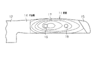
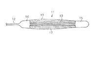
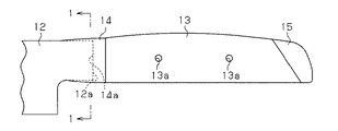
図1及び図2に示すように、この包丁は柄部11と、この柄部11の先端部に連結された刃部12とにより構成されている。前記柄部11は中心部に位置する扁平状のステンレススチール製の本体13と、該本体13の先端部に一体形成された口金部14と、本体13の後端部に一体形成された尻金部15とを備えている。又、前記柄部11は前記本体13の両側面に対し前記口金部14と尻金部15との間に位置するように接触され、かつカシメピン16によりカシメ付けられた左右一対の木製の側板17,17を備えている。
Hereinafter, an embodiment in which the present invention is embodied in a kitchen knife will be described with reference to FIGS.
As shown in FIGS. 1 and 2, the knife is composed of a
次に、上記の包丁の製造方法について説明する。
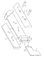
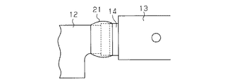
図3に示すように、前記本体13及び側板17には、前記カシメピン16を貫通する孔13a,17aが複数箇所に形成されている。前記柄部11の本体13、口金部14及び尻金部15は、粗加工された状態を示す。前記口金部14は四角ブロック状に形成され、その先端部の左右両側面には先端程幅狭となるテーパ面14a,14bが形成されている。前記口金部14の先端面14cの左右方向の中心部から口金部14の内部に向かって挿入溝14dが上下方向に貫通するように形成されている。前記刃部12の後端部に一体形成された中子12aの上下方向の幅Wは、前記挿入溝14dの上下方向の長さLよりも小さく(例えば1〜2mm)形成されている。
Next, the manufacturing method of said knife is demonstrated.
As shown in FIG. 3, the
次に、前記口金部14に対する刃部12の連結方法について説明する。
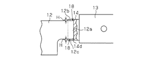
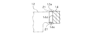
図4及び図5に示すように、前記口金部14の挿入溝14dに刃部12の中子12aの先端部を挿入するとともに、中子12aの上下両端面12b,12cをそれぞれ挿入溝14dの内部に同じ寸法H(例えば0.5〜1.0mm)だけ没入させて、溝部18を形成し、この状態を溶接作業に先立って図示しない保持装置により保持する。
Next, the connection method of the
As shown in FIG. 4 and FIG. 5, while inserting the front-end | tip part of the
次に、図6及び図7に示すように、前記口金部14の挿入溝14dの先端開口縁及び前記溝部18を覆うように肉盛り溶接を行って溶接部21を形成する。この溶接部21によって口金部14と刃部12の中子12aが連結される。
Next, as shown in FIGS. 6 and 7, build-up welding is performed so as to cover the end opening edge of the
さらに、図8及び図9に示すように、粗仕上げ状態の前記口金部14及び溶接部21を手作業により予め想定された外形状に研削加工を行い、口金部14が図9に示すように左右の両側面が滑らかな曲面になるように、かつ口金部14の横断面が図10に示すように楕円形状になるように仕上げ加工する。この仕上げ加工に際して、前記口金部14の挿入溝14dの先端開口縁及び中子12aの上下の端面12b,12cが露出して境界線が現われないようにする。
Further, as shown in FIGS. 8 and 9, the
上記口金部14の手作業による仕上げ加工に続いて、手作業により尻金部15の仕上げ加工を行い、その外形状を滑らかな曲面形状にする。
最後に、図8及び図9に示す前記本体13の左右両側面に側板17を接触してカシメピン16により側板17を本体13に連結すると、図1及び図2に示す包丁を製造することができる。
Subsequent to the finishing process of the
Finally, when the
上記実施形態の刃物によれば、以下のような効果を得ることができる。
(1)上記実施形態では、口金部14に挿入溝14dを形成し、この挿入溝14dに刃部12の中子12aを挿入し、肉盛溶接により溶接部21を形成した後、該溶接部21をグラインダ等を用いて手作業により仕上げ加工して、口金部14と中子12aを連結するようにした。このため、従来の口金部と中子の連結に用いられる開先溶接と比較して、溶接作業を容易に行うこができるとともに、口金部14と中子12aの連結強度を向上することができる。又、挿入溝14dに中子12aを挿入したので、本体13及び口金部14の中心線の延長上に刃部12を真っ直ぐに位置させることもできる。
According to the blade of the above embodiment, the following effects can be obtained.
(1) In the above embodiment, the
(2)上記実施形態では、本体13に対し口金部14と尻金部15を一体に形成したので、部品点数を低減して、製造を容易に行い、コストを低減することができる。
(3)上記実施形態では、口金部14の挿入溝14dに刃部12の中子12aを挿入して、中子12aの上下両端面12b,12cを挿入溝14dに没入させて溝部18を形成し、この溝部18に溶接部21の肉部を進入させたので、口金部14と中子12aの連結強度を向上することができる。
(2) In the above embodiment, since the
(3) In the above embodiment, the
なお、上記実施形態は以下のように変更してもよい。
・図11に示すように、前記口金部14の挿入溝14dの下部に中子12aの下端縁を係止する係止部14eを形成してもよい。この場合には、口金部14と中子12aの位置合わせを容易に行うことができる。
In addition, you may change the said embodiment as follows.
-As shown in FIG. 11, you may form the latching | locking part 14e which latches the lower end edge of the
・図12に示すように、挿入溝14dをテーパ状に形成するとともに、中子12aもテーパ状に形成してもよい。この場合には、口金部14と中子12aの位置合わせを確実に行うことができる。
As shown in FIG. 12, the
・図13に示すように尻金部15の形状を変更してもよい。
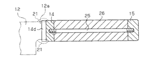
。図14に示すように前記口金部14及び尻金部15をそれぞれ単体で形成し、口金部14と尻金部15を連結ボルト25により連結し、連結ボルト25の外周に対し口金部14と尻金部15の間に位置する柄部本体26を装着してもよい。
-You may change the shape of the
. As shown in FIG. 14, the
・図示しないが、柄部11を金属により一体に形成してもよい。
-Although not shown in figure, you may integrally form the
11…柄部、12…刃部、12a…中子、13…本体、14…口金部、14d…挿入溝、14e…係止部、15…尻金部、17…側板、21…溶接部。
DESCRIPTION OF
Claims (5)
Priority Applications (1)
| Application Number | Priority Date | Filing Date | Title |
|---|---|---|---|
| JP2006115942A JP4607046B2 (en) | 2006-04-19 | 2006-04-19 | Knife |
Applications Claiming Priority (1)
| Application Number | Priority Date | Filing Date | Title |
|---|---|---|---|
| JP2006115942A JP4607046B2 (en) | 2006-04-19 | 2006-04-19 | Knife |
Publications (2)
| Publication Number | Publication Date |
|---|---|
| JP2007282999A true JP2007282999A (en) | 2007-11-01 |
| JP4607046B2 JP4607046B2 (en) | 2011-01-05 |
Family
ID=38755295
Family Applications (1)
| Application Number | Title | Priority Date | Filing Date |
|---|---|---|---|
| JP2006115942A Active JP4607046B2 (en) | 2006-04-19 | 2006-04-19 | Knife |
Country Status (1)
| Country | Link |
|---|---|
| JP (1) | JP4607046B2 (en) |
Citations (10)
| Publication number | Priority date | Publication date | Assignee | Title |
|---|---|---|---|---|
| JPS413659Y1 (en) * | 1964-04-14 | 1966-02-26 | ||
| JPS4925080U (en) * | 1972-06-02 | 1974-03-04 | ||
| JPS536447U (en) * | 1976-06-30 | 1978-01-20 | ||
| JPS5481965A (en) * | 1977-12-09 | 1979-06-29 | Hideo Tomita | Method of making kitchen knife |
| JPH0191970A (en) * | 1987-09-30 | 1989-04-11 | Mishima Hamono:Kk | Method for fitting handle of kitchen apparatus |
| JPH06154430A (en) * | 1991-06-28 | 1994-06-03 | Ja Henckels Zwillingswerk Ag | Knife |
| JPH08299617A (en) * | 1995-05-09 | 1996-11-19 | Hiroo Choji | Kitchen knife |
| JP2000176184A (en) * | 1998-12-15 | 2000-06-27 | Fuji Corporation:Kk | Kitchen knife, its manufacture, and handle for kitchen knife |
| JP2006254967A (en) * | 2005-03-15 | 2006-09-28 | Kai R & D Center Co Ltd | Cutter with handle |
| JP2007152476A (en) * | 2005-12-02 | 2007-06-21 | Tadafusa:Kk | Handle of cooking utensils |
-
2006
- 2006-04-19 JP JP2006115942A patent/JP4607046B2/en active Active
Patent Citations (10)
| Publication number | Priority date | Publication date | Assignee | Title |
|---|---|---|---|---|
| JPS413659Y1 (en) * | 1964-04-14 | 1966-02-26 | ||
| JPS4925080U (en) * | 1972-06-02 | 1974-03-04 | ||
| JPS536447U (en) * | 1976-06-30 | 1978-01-20 | ||
| JPS5481965A (en) * | 1977-12-09 | 1979-06-29 | Hideo Tomita | Method of making kitchen knife |
| JPH0191970A (en) * | 1987-09-30 | 1989-04-11 | Mishima Hamono:Kk | Method for fitting handle of kitchen apparatus |
| JPH06154430A (en) * | 1991-06-28 | 1994-06-03 | Ja Henckels Zwillingswerk Ag | Knife |
| JPH08299617A (en) * | 1995-05-09 | 1996-11-19 | Hiroo Choji | Kitchen knife |
| JP2000176184A (en) * | 1998-12-15 | 2000-06-27 | Fuji Corporation:Kk | Kitchen knife, its manufacture, and handle for kitchen knife |
| JP2006254967A (en) * | 2005-03-15 | 2006-09-28 | Kai R & D Center Co Ltd | Cutter with handle |
| JP2007152476A (en) * | 2005-12-02 | 2007-06-21 | Tadafusa:Kk | Handle of cooking utensils |
Also Published As
| Publication number | Publication date |
|---|---|
| JP4607046B2 (en) | 2011-01-05 |
Similar Documents
| Publication | Publication Date | Title |
|---|---|---|
| KR20130052561A (en) | Cutting tool | |
| JPH09253250A (en) | Golf club head and its manufacture | |
| JP2007282999A (en) | Cutlery | |
| EP1854419B1 (en) | Box joint medical tool apparatus and method of manufacture | |
| JP2004141350A (en) | Method for manufacturing golf club head | |
| KR101743993B1 (en) | Separable fixing equipment use aircraft parts and that method | |
| JP5131011B2 (en) | Method for manufacturing front fork bracket and method for manufacturing structure with lid | |
| JP6271319B2 (en) | Laser welding method | |
| JP2003285162A (en) | Welded joint and frame structure of chair using the same | |
| JP2007061944A (en) | Grip and manual cutlery using with it | |
| TWM560380U (en) | Patterned steel knife combination structure | |
| JPH07100194B2 (en) | Cutting die for making bending cuts in square pipes, etc. | |
| KR200415048Y1 (en) | Cripe of Silver ware | |
| JP6882731B2 (en) | Vehicle subframe | |
| KR101741047B1 (en) | Self drill screw nail | |
| CN109746574A (en) | Welding method and turning joint element | |
| JP5522581B1 (en) | Twist drill | |
| CN208825733U (en) | A kind of combination cutter | |
| CN213462365U (en) | Electrode slice structure with stable structure | |
| CN209021363U (en) | The cutter of burr at a kind of two hole intersections of removal | |
| JP2004024720A (en) | Knife to be disassembled | |
| JP3073736U (en) | Tile | |
| JP2005207010A (en) | Floor board | |
| JP3011331U (en) | Tool holder for knife | |
| JP2006141663A (en) | Hatchet and manufacturing method of hatchet |
Legal Events
| Date | Code | Title | Description |
|---|---|---|---|
| A977 | Report on retrieval |
Free format text: JAPANESE INTERMEDIATE CODE: A971007 Effective date: 20081023 |
|
| A131 | Notification of reasons for refusal |
Free format text: JAPANESE INTERMEDIATE CODE: A131 Effective date: 20091117 |
|
| A521 | Request for written amendment filed |
Free format text: JAPANESE INTERMEDIATE CODE: A523 Effective date: 20100115 |
|
| A131 | Notification of reasons for refusal |
Free format text: JAPANESE INTERMEDIATE CODE: A131 Effective date: 20100525 |
|
| A521 | Request for written amendment filed |
Free format text: JAPANESE INTERMEDIATE CODE: A523 Effective date: 20100726 |
|
| TRDD | Decision of grant or rejection written | ||
| A01 | Written decision to grant a patent or to grant a registration (utility model) |
Free format text: JAPANESE INTERMEDIATE CODE: A01 Effective date: 20100921 |
|
| A01 | Written decision to grant a patent or to grant a registration (utility model) |
Free format text: JAPANESE INTERMEDIATE CODE: A01 |
|
| A61 | First payment of annual fees (during grant procedure) |
Free format text: JAPANESE INTERMEDIATE CODE: A61 Effective date: 20101006 |
|
| R150 | Certificate of patent or registration of utility model |
Ref document number: 4607046 Country of ref document: JP Free format text: JAPANESE INTERMEDIATE CODE: R150 Free format text: JAPANESE INTERMEDIATE CODE: R150 |
|
| FPAY | Renewal fee payment (event date is renewal date of database) |
Free format text: PAYMENT UNTIL: 20131015 Year of fee payment: 3 |
|
| R250 | Receipt of annual fees |
Free format text: JAPANESE INTERMEDIATE CODE: R250 |
|
| R250 | Receipt of annual fees |
Free format text: JAPANESE INTERMEDIATE CODE: R250 |
|
| R250 | Receipt of annual fees |
Free format text: JAPANESE INTERMEDIATE CODE: R250 |
|
| R250 | Receipt of annual fees |
Free format text: JAPANESE INTERMEDIATE CODE: R250 |