JP2007282977A - Electric rice cooker - Google Patents
Electric rice cooker Download PDFInfo
- Publication number
- JP2007282977A JP2007282977A JP2006115555A JP2006115555A JP2007282977A JP 2007282977 A JP2007282977 A JP 2007282977A JP 2006115555 A JP2006115555 A JP 2006115555A JP 2006115555 A JP2006115555 A JP 2006115555A JP 2007282977 A JP2007282977 A JP 2007282977A
- Authority
- JP
- Japan
- Prior art keywords
- inner pot
- rice cooker
- lid
- end opening
- opening edge
- Prior art date
- Legal status (The legal status is an assumption and is not a legal conclusion. Google has not performed a legal analysis and makes no representation as to the accuracy of the status listed.)
- Pending
Links
Images


Landscapes
- Cookers (AREA)
Abstract
Description
本願発明は、電気炊飯器に関し、さらに詳しくは保温性能を向上させることにより、省エネ化を企図した電気炊飯器に関するものである。 The present invention relates to an electric rice cooker, and more particularly to an electric rice cooker designed to save energy by improving heat insulation performance.
近年、環境問題(例えば、地球温暖化問題)への対応として、消費電力量の低減が様々な場面で取り沙汰されてきており、電気炊飯器においても、法令においてエネルギー消費効率のトップランナー方式における基準達成状況の表示が義務づけられている。このような時代背景を受け、電気炊飯器が外気に対して余計な放熱をしている箇所を抑え、放熱を低減することが省エネに対する重要課題となっている。 In recent years, as a response to environmental problems (for example, global warming problems), reduction of power consumption has been taken in various situations, and even in the electric rice cooker, the standards in the top runner method of energy consumption efficiency are achieved by law. The display of the situation is obligatory. In response to such a background of the times, it is an important issue for energy saving to suppress the heat dissipation of the electric rice cooker from the outside air and to reduce the heat dissipation.
一般に、電気炊飯器においては、内鍋の上端開口縁に当接されるシールパッキンによって、内鍋内と外部とを遮断して保温性能の向上を図ることが行われている(特許文献1参照)。 Generally, in an electric rice cooker, the heat insulation performance is improved by shutting off the inside and outside of the inner pot with a seal packing that is in contact with the upper end opening edge of the inner pot (see Patent Document 1). ).
ところが、上記特許文献1に開示されているように、内鍋の上端開口縁に当接されるシールパッキンによって内鍋内と外部とを遮断する方法の場合、内鍋の上端開口縁(例えば、フランジ部)の外周側からの放熱を防ぎきれないという不具合がある。
However, as disclosed in the above-mentioned
本願発明は、上記の点に鑑みてなされたもので、内鍋の上端開口縁の外周側からの放熱を防ぐことにより、消費電力量の低減を図ることを目的としている。 This invention is made | formed in view of said point, and aims at reduction of power consumption by preventing the thermal radiation from the outer peripheral side of the upper end opening edge of an inner pot.
本願発明では、上記課題を解決するための第1の手段として、内鍋を内蔵した炊飯器本体と、該炊飯器本体の蓋体とを備えた電気炊飯器において、前記内鍋の上端開口縁に当接される環状のシールパッキンを付設するとともに、前記蓋体の裏面に、前記内鍋の上端開口縁を覆う環状部材を設けている。 In this invention, in the electric rice cooker provided with the rice cooker main body which incorporated the inner pot as a 1st means for solving the said subject, and the cover body of this rice cooker main body, the upper end opening edge of the said inner pot An annular seal packing that is in contact with the inner pot is provided, and an annular member that covers the upper end opening edge of the inner pot is provided on the back surface of the lid.
上記のように構成したことにより、内鍋内と外部との熱遮断は、内鍋の上端開口縁に当接されるシールパッキンにより行われる一方、内鍋の上端開口縁の外周側からの放熱は、蓋体の裏面に設けられた環状部材により行われることとなる。従って、炊飯器本体から外部への放熱を可及的に低減して内鍋および内部のご飯の温度低下を抑えることができることとなり、消費電力量の低減を実現することができる。 By configuring as described above, heat insulation between the inside and outside of the inner pot is performed by seal packing that is in contact with the upper end opening edge of the inner pot, while heat radiation from the outer peripheral side of the upper end opening edge of the inner pot. Is performed by an annular member provided on the back surface of the lid. Therefore, the heat radiation from the rice cooker body to the outside can be reduced as much as possible to suppress the temperature drop of the inner pot and the internal rice, and the power consumption can be reduced.
本願発明では、上記課題を解決するための第2の手段として、内鍋を内蔵した炊飯器本体と、該炊飯器本体の蓋体と、前記内鍋の上端開口縁を前記蓋体の閉蓋時に閉塞する内蓋とを備えた電気炊飯器において、前記内蓋の表裏面に、第1および第2の環状部材を設けるとともに、前記第1の環状部材を、前記内鍋の上端開口縁を覆う形状とする一方、前記第2の環状部材を、前記内鍋の上端開口縁に当接されるシールパッキンとしている。 In this invention, as a 2nd means for solving the said subject, the rice cooker main body with which the inner pot was incorporated, the cover body of this rice cooker main body, and the upper end opening edge of the said inner pot were closed with the said cover body. In the electric rice cooker provided with an inner lid that is sometimes closed, the first and second annular members are provided on the front and back surfaces of the inner lid, and the upper end opening edge of the inner pot is disposed on the first annular member. While making it the shape to cover, the said 2nd annular member is made into the seal packing contact | abutted to the upper end opening edge of the said inner pot.
上記のように構成したことにより、内鍋内と外部との熱遮断は、内鍋の上端開口縁に当接される第2の環状部材(即ち、シールパッキン)により行われる一方、内鍋の上端開口縁の外周側からの放熱は、内鍋の上端開口縁を覆う形状とされた第1の環状部材により行われることとなる。従って、炊飯器本体から外部への放熱を可及的に低減して内鍋および内部のご飯の温度低下を抑えることができることとなり、消費電力量の低減を実現することができる。 By configuring as described above, the heat insulation between the inside and outside of the inner pot is performed by the second annular member (that is, the seal packing) that is in contact with the upper end opening edge of the inner pot. Heat dissipation from the outer peripheral side of the upper end opening edge is performed by a first annular member having a shape covering the upper end opening edge of the inner pot. Therefore, the heat radiation from the rice cooker body to the outside can be reduced as much as possible to suppress the temperature drop of the inner pot and the internal rice, and the power consumption can be reduced.
本願発明では、上記課題を解決するための第3の手段として、内鍋を内蔵した炊飯器本体と、該炊飯器本体の蓋体とを備えた電気炊飯器において、前記内鍋の上端開口縁に当接される環状のシールパッキンを付設するとともに、前記蓋体の裏面を構成する部材に、前記内鍋の上端開口縁を覆う環状のリブを一体に形成している。 In this invention, as a 3rd means for solving the said subject, in the electric rice cooker provided with the rice cooker main body which incorporated the inner pot, and the cover body of this rice cooker main body, the upper end opening edge of the said inner pot An annular seal packing that is in contact with the inner pot is formed, and an annular rib that covers the upper end opening edge of the inner pot is formed integrally with a member that forms the back surface of the lid.
上記のように構成したことにより、内鍋内と外部との熱遮断は、内鍋の上端開口縁に当接されるシールパッキンにより行われる一方、内鍋の上端開口縁の外周側からの放熱は、蓋体の裏面を構成する部材に一体形成された環状のリブにより行われることとなる。従って、炊飯器本体から外部への放熱を可及的に低減して内鍋および内部のご飯の温度低下を抑えることができることとなり、消費電力量の低減を実現することができる。 By configuring as described above, heat insulation between the inside and outside of the inner pot is performed by seal packing that is in contact with the upper end opening edge of the inner pot, while heat radiation from the outer peripheral side of the upper end opening edge of the inner pot. Is performed by an annular rib formed integrally with a member constituting the back surface of the lid. Therefore, the heat radiation from the rice cooker body to the outside can be reduced as much as possible to suppress the temperature drop of the inner pot and the internal rice, and the power consumption can be reduced.
本願発明の第1の手段によれば、内鍋を内蔵した炊飯器本体と、該炊飯器本体の蓋体とを備えた電気炊飯器において、前記内鍋の上端開口縁に当接される環状のシールパッキンを付設するとともに、前記蓋体の裏面に、前記内鍋の上端開口縁を覆う環状部材を設けて、内鍋内と外部との熱遮断は、内鍋の上端開口縁に当接されるシールパッキンにより行われる一方、内鍋の上端開口縁の外周側からの放熱は、蓋体の裏面に設けられた環状部材により行われるようにしたので、炊飯器本体から外部への放熱を可及的に低減して内鍋および内部のご飯の温度低下を抑えることができることとなり、消費電力量の低減を実現することができるという効果がある。 According to the 1st means of this invention, in the electric rice cooker provided with the rice cooker main body which incorporated the inner pot, and the cover body of this rice cooker main body, the cyclic | annular form contact | abutted at the upper end opening edge of the said inner pot And an annular member covering the upper end opening edge of the inner pot is provided on the back surface of the lid, and the heat insulation between the inner pot and the outside is in contact with the upper end opening edge of the inner pot. The heat from the outer peripheral side of the top opening edge of the inner pot is performed by the annular member provided on the back surface of the lid, so that heat is released from the rice cooker body to the outside. It is possible to reduce as much as possible to suppress the temperature drop of the inner pot and the internal rice, and there is an effect that reduction of power consumption can be realized.
本願発明の第2の手段によれば、内鍋を内蔵した炊飯器本体と、該炊飯器本体の蓋体と、前記内鍋の上端開口縁を前記蓋体の閉蓋時に閉塞する内蓋とを備えた電気炊飯器において、前記内蓋の表裏面に、第1および第2の環状部材を設けるとともに、前記第1の環状部材を、前記内鍋の上端開口縁を覆う形状とする一方、前記第2の環状部材を、前記内鍋の上端開口縁に当接されるシールパッキンとして、内鍋内と外部との熱遮断は、内鍋の上端開口縁に当接される第2の環状部材(即ち、シールパッキン)により行われる一方、内鍋の上端開口縁の外周側からの放熱は、内鍋の上端開口縁を覆う形状とされた第1の環状部材により行われるようにしたので、炊飯器本体から外部への放熱を可及的に低減して内鍋および内部のご飯の温度低下を抑えることができることとなり、消費電力量の低減を実現することができるという効果がある。 According to the 2nd means of this invention, the rice cooker main body which incorporated the inner pot, the cover body of this rice cooker main body, and the inner cover which obstruct | occludes the upper end opening edge of the said inner pot at the time of the said cover body closing. While providing the first and second annular members on the front and back surfaces of the inner lid, the first annular member is shaped to cover the upper end opening edge of the inner pot, The second annular member is used as a seal packing that comes into contact with the upper end opening edge of the inner pot, and the heat insulation between the inner pot and the outside is a second annular form that comes into contact with the upper end opening edge of the inner pot. On the other hand, heat is released from the outer peripheral side of the upper end opening edge of the inner pot by the first annular member that is shaped to cover the upper end opening edge of the inner pot while being performed by the member (ie, seal packing). , Reduce the heat dissipation from the rice cooker body to the outside as much as possible to lower the temperature of the inner pot and the internal rice It and it can be suppressed, there is an effect that it is possible to realize a reduction in power consumption.
本願発明の第3の手段によれば、内鍋を内蔵した炊飯器本体と、該炊飯器本体の蓋体とを備えた電気炊飯器において、前記内鍋の上端開口縁に当接される環状のシールパッキンを付設するとともに、前記蓋体の裏面を構成する部材に、前記内鍋の上端開口縁を覆う環状のリブを一体に形成して、内鍋内と外部との熱遮断は、内鍋の上端開口縁に当接されるシールパッキンにより行われる一方、内鍋の上端開口縁の外周側からの放熱は、蓋体の裏面を構成する部材に一体形成された環状のリブにより行われるようにしたので、炊飯器本体から外部への放熱を可及的に低減して内鍋および内部のご飯の温度低下を抑えることができることとなり、消費電力量の低減を実現することができるという効果がある。 According to the 3rd means of this invention, in the electric rice cooker provided with the rice cooker main body which incorporated the inner pot, and the cover body of this rice cooker main body, the cyclic | annular form contact | abutted at the upper end opening edge of the said inner pot And an annular rib that covers the upper end opening edge of the inner pot is formed integrally with the member that constitutes the back surface of the lid body, so that heat insulation between the inner pot and the outside is On the other hand, heat is released from the outer peripheral side of the upper end opening edge of the inner pot by an annular rib formed integrally with a member constituting the back surface of the lid body, while the seal packing is brought into contact with the upper end opening edge of the pot. Because it did so, it will be possible to reduce the heat dissipation from the rice cooker body to the outside as much as possible to suppress the temperature drop of the inner pot and the internal rice, and the effect that reduction of power consumption can be realized There is.
以下、添付の図面を参照して、本願発明を幾つかの好適な実施の形態について説明する。 The preferred embodiments of the present invention will be described below with reference to the accompanying drawings.
第1の実施の形態
図1ないし図4には、本願発明の第1の実施の形態にかかる電気炊飯器が示されている。
First Embodiment FIGS. 1 to 4 show an electric rice cooker according to a first embodiment of the present invention.
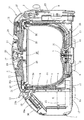
この電気炊飯器は、内部に炊飯用の内鍋3を収納し得るように構成され且つ空間部4を有する二重構造の炊飯器本体1と、該炊飯器本体1の上部開口を開閉且つ着脱自在に覆蓋する蓋体2とを備えている。
This electric rice cooker is configured to accommodate an
前記炊飯器本体1は、外側壁を構成する板金製の外ケース5と、底壁を構成する合成樹脂製の底部材6と、肩部を構成する合成樹脂製の肩部材7と、内周壁を構成する合成樹脂製の有底筒状の保護枠8とからなっており、前記外ケース5、底部材6、肩部材7および保護枠8に囲まれて前記空間部4が形成されている。なお、前記保護枠8内には、前記内鍋3が取り出し可能に収納されることとなっている。
The
前記保護枠8の底面中央部には、内鍋温度を検出するための温度検出手段として作用するセンタセンサー9を臨ませるためのセンサー穴10が形成されている。
A
前記センサー穴10を包囲するように炊飯時における加熱手段として作用する環状の電磁誘導コイル(以下、IHコイルという)11が前記保護枠8の底面および該底面から側周面に至る間の湾曲部に対応して配設されている。該IHコイル11は、交番磁界(換言すれば、電磁波)を発生するものであり、該交番磁界の電磁誘導により前記内鍋3に渦電流を発生させ、該渦電流の抵抗熱を利用して内鍋3を加熱するものとされている。なお、内鍋3は、IHコイル11により渦電流を発生させることのできる材質(例えば、磁性体材料)により構成される。
An annular electromagnetic induction coil (hereinafter referred to as an IH coil) 11 acting as a heating means during rice cooking so as to surround the
前記IHコイル11は、前記保護枠8の底面に対して固定されたコイルダイ12と前記保護枠8の底面との間に挟持されている。符号13はフェライトコアであり、前記IHコイル11の下方において4本が放射状に配設されていて、IHコイル11による磁気が下方に存在する機器に対して影響を及ぼさないように遮蔽する作用をなす。
The
前記センサー穴10内には、前記内鍋3の底部に対して接触するようにしてセンタセンサー9が設けられている。また、前記保護枠8の側周面には、保温時における加熱手段として作用する保温ヒータ14が取り付けられている。保温ヒータ14に代えてIHコイルを採用する場合もある。また、前記保護枠8の外側には、外方への放熱を遮断するための円筒状の断熱材23が配設されている。また、前記保護枠8における底面および湾曲面には、当該部分からの放熱を抑制するためのメラミン樹脂層33が設けられている。また、前記保護枠8の上端と肩部材7との間には、前記内鍋3に接する環状のパッキン34が介設されている。このようにすると、内鍋3から外方への放熱を可及的に抑制することができることとなり、保温性能の向上、消費電力量の低減に大いに寄与する。
A
前記炊飯器本体1の底部(即ち、底部材6の内底部)には、前記IHコイル11の通電制御を行うためのパワートランジスタおよび整流用ダイオードブリッジ(図示省略)等の電子部品を冷却するヒートシンク15へ冷却風を圧送する電子部品冷却用ファン16が配設されている。また、前記炊飯器本体1の底壁(具体的には、底部材6)には、前記電子部品冷却用ファン16に対向して空気入口17,17・・が形成されている。符号18は前記電子部品が配設されている電源基板である。
A heat sink for cooling electronic components such as a power transistor and a rectifier diode bridge (not shown) for controlling energization of the
一方、前記蓋体2は、外面を構成する合成樹脂製の上板19と、内面を構成する合成樹脂製の下板20とによって構成されている。蓋下板20は、前記上板19より小径とされており、上板19と下板20との結合部位は、後述する環状部材31の取付部とされている。この蓋体2は、前記肩部材7(換言すれば、炊飯器本体1)の一側(即ち、背面側)に枢支されたヒンジユニット21を介して炊飯器本体1に対して弧回動自在且つ着脱自在に取り付けられている。符号22は蓋体2内に配設された断熱材である。
On the other hand, the
そして、前記蓋体2の中央部には、前記上板19から垂設された筒部24が形成されており、該筒部24内には、炊飯時に発生する水蒸気を外部へ排出するための蒸気排出通路26を有するスチームキャップ25が着脱自在に取り付けられている。該スチームキャップ25内には、調圧弁として作用するボール弁27が配設されている。符号28は前記筒部24の口縁に前記スチームキャップ25を収納すべく形成された窪み部である。
And the
前記スチームキャップ25の下端には、前記蓋体2の閉止時に前記内鍋3の開口部を密閉するための内蓋29が取り付けられている。該内蓋29は、アルミ合金等の熱良導体からなっている。符号30は内蓋29の周縁と内鍋3の上端開口部との間をシールするシールパッキンである。
An
前記肩部材7には、肩ヒータ32が設けられている。該肩ヒータ32に対しては、前記蓋体2の閉止時に前記内蓋29の外周縁が圧接されることとなっており、内蓋29は肩ヒータ32からの熱伝導により加熱されることとなっている。
The
このようにすると、肩ヒータ32からの熱伝導により内蓋29が加熱されることとなり、炊飯時においては、おネバが内蓋29への接触により成長を阻止されるし、保温時においては、内蓋29からの放熱により、内鍋3内のご飯の表面温度を上げることができるとともに、内蓋29に付着する水滴を蒸発させる。
If it does in this way, the
前記肩部材7における反ヒンジ側(即ち、蓋体2をロックするロック機構35が設けられている側)には、各種スイッチ(例えば、炊飯スイッチ、予約スイッチ、保温スイッチ等)および液晶表示部を備えた操作パネル部36とその操作基板36aとが設けられている。
Various switches (for example, a rice cooking switch, a reservation switch, a heat retention switch, etc.) and a liquid crystal display unit are provided on the side opposite to the hinge of the shoulder member 7 (that is, the side where the
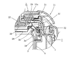
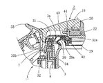
ところで、本実施の形態においては、図2ないし図4に示すように、前記蓋体2の裏面には、前記内鍋3の上端開口縁を覆う環状部材31が設けられている。該環状部材31は、シリコンゴム等の耐熱弾性部材からなっており、その内周端部31aは、前記上板19と下板20との結合部位において上板19と下板20との間に挟持固定される一方、その外周端部31bは、肩部材7に取り付けられた肩ヒータ32の外側にまで達している。また、この環状部材31には、蓋体2と内蓋29との間をシールするシール部37が一体に形成されている。なお、前記環状部材31は、ヒンジユニット21側においては該ヒンジユニット21の存在によって内鍋3の上端開口縁を覆う形状となりにくいところから、図3に示すように、外周部分を切除した形状とされている。また、ロック機構35とヒンジユニット21とを結ぶ線に直交する部位においては、前記環状部材31の外周端部31bは、図4に示すように、内鍋3の上端開口縁に形成されたフランジ部3aの外周部に取り付けられた耐熱合成樹脂製のツマミ38の外周端部に当接されることとなっている。
By the way, in this Embodiment, as shown in FIG. 2 thru | or FIG. 4, the cyclic |
上記のように構成したことにより、内鍋3内と外部との熱遮断は、内鍋3の上端開口縁に当接されるシールパッキン30により行われる一方、内鍋3の上端開口縁の外周側からの放熱は、蓋体2の裏面に設けられた環状部材31により行われることとなる。従って、炊飯器本体1から外部への放熱を可及的に低減して内鍋3および内部のご飯の温度低下を抑えることができることとなり、消費電力量の低減を実現することができる。しかも、環状部材31に、蓋体2と内蓋29との間をシールするシール部37を一体形成したことにより、蓋体2と内蓋29との間からの外方への放熱を遮断することが可能となり、保温性能がより一層向上する。
By configuring as described above, heat insulation between the inside and outside of the
なお、本実施の形態の場合、内蓋29を省略してもよく、その場合には、環状部材31に一体形成されたシール部37も省略される。
In the case of the present embodiment, the
第2の実施の形態
図5ないし図7には、本願発明の第2の実施の形態にかかる電気炊飯器の要部が示されている。
2nd Embodiment The principal part of the electric rice cooker concerning the 2nd Embodiment of this invention is shown by FIG. 5 thru | or FIG.
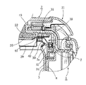
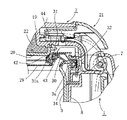
この場合、内蓋29の表裏面には、第1および第2の環状部材31,30が設けられており、前記第1の環状部材31は、内鍋3の上端開口縁を覆う形状とされる一方、前記第2の環状部材30は、内鍋3の上端開口縁に当接されるシールパッキンとされている。そして、前記第1および第2の環状部材31,30は、内蓋29の表面側および裏面側において前記内蓋29との間に前記第1および第2の環状部材31,30を挟持する固定部材39,40をビス固定することにより内蓋29に取り付けられることとなっている。また、前記第1の環状部材31は、前述の第1の実施の形態における環状部材と同様に、シリコンゴム等の耐熱弾性部材からなっており、その内周端部には、蓋体2における下板20の外周縁部に当接して蓋体2と内蓋29との間をシールするシール部41が一体に形成されている。
In this case, first and second
上記のように構成したことにより、内鍋3内と外部との熱遮断は、内鍋3の上端開口縁に当接される第2の環状部材(即ち、シールパッキン30)により行われる一方、内鍋3の上端開口縁の外周側からの放熱は、内鍋3の上端開口縁を覆う形状とされた第1の環状部材31により行われることとなる。従って、炊飯器本体1から外部への放熱を可及的に低減して内鍋3および内部のご飯の温度低下を抑えることができることとなり、消費電力量の低減を実現することができる。しかも、第2の環状部材31に、蓋体2と内蓋29との間をシールするシール部41を一体形成したことにより、蓋体2と内蓋29との間からの外方への放熱を遮断することが可能となり、保温性能がより一層向上する。
By configuring as described above, heat insulation between the inside and outside of the
その他の構成および作用効果は、第1の実施の形態におけると同様なので説明を省略する。 Since other configurations and operational effects are the same as those in the first embodiment, the description thereof is omitted.
第3の実施の形態
図8ないし図10には、本願発明の第3の実施の形態にかかる電気炊飯器の要部が示されている。
3rd Embodiment The principal part of the electric rice cooker concerning 3rd Embodiment of this invention is shown by FIG. 8 thru | or FIG.
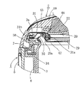
この場合、内蓋29の表裏面には、第1および第2の環状部材31,30が設けられており、前記第1の環状部材31は、内鍋3の上端開口縁を覆う形状とされる一方、前記第2の環状部材30は、内鍋3の上端開口縁に当接されるシールパッキンとされている。そして、前記第1の環状部材31は、前記内蓋29において蓋体2における下板20の外周端部に対応する部位に形成された縦壁部29aの内周側に対して取付リング42を介して固定される一方、前記第2の環状部材30は、前記縦壁部29aの外周側に対して取付リング43を介して固定されている。また、この場合、第1の環状部材31における内周側部位が、蓋体2における下板20の外周縁部に当接して蓋体2と内蓋29との間をシールするシール部44とされている。
In this case, first and second
上記のように構成したことにより、内鍋3内と外部との熱遮断は、内鍋3の上端開口縁に当接される第2の環状部材(即ち、シールパッキン30)により行われる一方、内鍋3の上端開口縁の外周側からの放熱は、内鍋3の上端開口縁を覆う形状とされた第1の環状部材31により行われることとなる。従って、炊飯器本体1から外部への放熱を可及的に低減して内鍋3および内部のご飯の温度低下を抑えることができることとなり、消費電力量の低減を実現することができる。しかも、第2の環状部材31における内周側部位を、蓋体2における下板20の外周縁部に当接して蓋体2と内蓋29との間をシールするシール部44としたことにより、蓋体2と内蓋29との間からの外方への放熱を遮断することが可能となり、保温性能がより一層向上する。
By configuring as described above, heat insulation between the inside and outside of the
その他の構成および作用効果は、第1の実施の形態におけると同様なので説明を省略する。 Since other configurations and operational effects are the same as those in the first embodiment, the description thereof is omitted.
第4の実施の形態
図11には、本願発明の第4の実施の形態にかかる電気炊飯器の要部が示されている。
4th Embodiment The principal part of the electric rice cooker concerning the 4th Embodiment of this invention is shown by FIG.
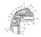
この場合、内鍋3の上端開口縁に当接される環状のシールパッキン30が付設されるとともに、蓋体2の裏面を構成する部材(例えば、下板20)には、前記内鍋3の上端開口縁を覆う環状のリブ45が一体に形成されている。該リブ45は、前記下板20の外周端部から肩部材7(具体的には、肩ヒータ32の外周側)に向かって垂設されている。また、内蓋29において、蓋体2の中央部(具体的には、スチームキャップ25)の直外周側には、蓋体2における下板20の内周縁部に当接して蓋体2と内蓋29との間をシールするシールパッキン46が取付具47により取り付けられている。
In this case, an annular seal packing 30 that is brought into contact with the upper end opening edge of the
上記のように構成したことにより、内鍋3内と外部との熱遮断は、内鍋3の上端開口縁に当接されるシールパッキン30により行われる一方、内鍋3の上端開口縁の外周側からの放熱は、蓋体2の裏面を構成する部材(例えば、下板20)に一体形成された環状のリブ45により行われることとなる。従って、炊飯器本体1から外部への放熱を可及的に低減して内鍋3および内部のご飯の温度低下を抑えることができることとなり、消費電力量の低減を実現することができる。しかも、下板20の外周端部から肩部材7(具体的には、肩ヒータ32の外周側)に向かってリブ45を垂設したことにより、上板19と下板20との間に充填される断熱材22の径を大きくできることとなり、断熱効果を向上させることができる。また、内蓋29において、蓋体2の中央部(具体的には、スチームキャップ25)の直外周側に、蓋体2における下板20の内周縁部に当接して蓋体2と内蓋29との間をシールするシールパッキン46を設けたことにより、蓋体2と内蓋29との間からの外方への放熱を遮断することが可能となり、保温性能がより一層向上する。
By configuring as described above, heat insulation between the inside and outside of the
その他の構成および作用効果は、第1の実施の形態におけると同様なので、説明を省略する。 Other configurations and operational effects are the same as those in the first embodiment, and thus description thereof is omitted.
本願発明は、上記各実施の形態に限定されるものではなく、発明の要旨を逸脱しない範囲において適宜設計変更可能なことは勿論である。 The invention of the present application is not limited to the above-described embodiments, and it goes without saying that the design can be changed as appropriate without departing from the scope of the invention.
1は炊飯器本体
2は蓋体
3は内鍋
30は第2の環状部材(シールパッキン)
31は第1の環状部材
37,41,44はシール部
45はリブ
1 is a
31 is a first
Claims (3)
Priority Applications (1)
| Application Number | Priority Date | Filing Date | Title |
|---|---|---|---|
| JP2006115555A JP2007282977A (en) | 2006-04-19 | 2006-04-19 | Electric rice cooker |
Applications Claiming Priority (1)
| Application Number | Priority Date | Filing Date | Title |
|---|---|---|---|
| JP2006115555A JP2007282977A (en) | 2006-04-19 | 2006-04-19 | Electric rice cooker |
Publications (1)
| Publication Number | Publication Date |
|---|---|
| JP2007282977A true JP2007282977A (en) | 2007-11-01 |
Family
ID=38755274
Family Applications (1)
| Application Number | Title | Priority Date | Filing Date |
|---|---|---|---|
| JP2006115555A Pending JP2007282977A (en) | 2006-04-19 | 2006-04-19 | Electric rice cooker |
Country Status (1)
| Country | Link |
|---|---|
| JP (1) | JP2007282977A (en) |
Cited By (2)
| Publication number | Priority date | Publication date | Assignee | Title |
|---|---|---|---|---|
| CN101856197A (en) * | 2010-06-10 | 2010-10-13 | 松下家电研究开发(杭州)有限公司 | Upper lid and electric rice cooker using same |
| WO2014199858A1 (en) * | 2013-06-12 | 2014-12-18 | 三菱電機株式会社 | Rice cooker |
Citations (5)
| Publication number | Priority date | Publication date | Assignee | Title |
|---|---|---|---|---|
| JPS5723221A (en) * | 1980-07-16 | 1982-02-06 | Mitsubishi Electric Corp | Manufacture of semiconductor device |
| JPH0236814A (en) * | 1988-07-27 | 1990-02-06 | Tiger Vacuum Bottle Co Ltd | Electric heating container |
| JPH02234720A (en) * | 1989-03-09 | 1990-09-17 | Mitsubishi Electric Corp | Electric rice cooker |
| JPH09313341A (en) * | 1996-05-29 | 1997-12-09 | Matsushita Electric Ind Co Ltd | Rice cooker |
| JP2002078605A (en) * | 2000-09-06 | 2002-03-19 | Tiger Vacuum Bottle Co Ltd | Rice cooking jar |
-
2006
- 2006-04-19 JP JP2006115555A patent/JP2007282977A/en active Pending
Patent Citations (5)
| Publication number | Priority date | Publication date | Assignee | Title |
|---|---|---|---|---|
| JPS5723221A (en) * | 1980-07-16 | 1982-02-06 | Mitsubishi Electric Corp | Manufacture of semiconductor device |
| JPH0236814A (en) * | 1988-07-27 | 1990-02-06 | Tiger Vacuum Bottle Co Ltd | Electric heating container |
| JPH02234720A (en) * | 1989-03-09 | 1990-09-17 | Mitsubishi Electric Corp | Electric rice cooker |
| JPH09313341A (en) * | 1996-05-29 | 1997-12-09 | Matsushita Electric Ind Co Ltd | Rice cooker |
| JP2002078605A (en) * | 2000-09-06 | 2002-03-19 | Tiger Vacuum Bottle Co Ltd | Rice cooking jar |
Cited By (2)
| Publication number | Priority date | Publication date | Assignee | Title |
|---|---|---|---|---|
| CN101856197A (en) * | 2010-06-10 | 2010-10-13 | 松下家电研究开发(杭州)有限公司 | Upper lid and electric rice cooker using same |
| WO2014199858A1 (en) * | 2013-06-12 | 2014-12-18 | 三菱電機株式会社 | Rice cooker |
Similar Documents
| Publication | Publication Date | Title |
|---|---|---|
| JP2005304709A (en) | Induction heating rice cooker | |
| JP2007282977A (en) | Electric rice cooker | |
| JP2007312867A (en) | Rice cooker | |
| JP5012250B2 (en) | Electric rice cooker | |
| JP6415475B2 (en) | Induction heating cooker | |
| JP2000262402A (en) | Pressure cooker | |
| JP5348454B2 (en) | rice cooker | |
| JP2008284010A (en) | Electric rice cooker | |
| JP2008272095A (en) | Electric rice cooker | |
| JP3374823B2 (en) | Electric rice cooker | |
| JP2009219741A (en) | Electric rice cooker | |
| JP4082368B2 (en) | Electric rice cooker | |
| JP5558295B2 (en) | rice cooker | |
| JP2007000328A (en) | Rice cooker | |
| JP5655832B2 (en) | rice cooker | |
| KR101873326B1 (en) | Inner side insulation assembly for eletric rice cooker | |
| JP3765288B2 (en) | Electromagnetic heating cooker | |
| JP3613225B2 (en) | rice cooker | |
| JP3912321B2 (en) | Electric rice cooker | |
| JP6516647B2 (en) | rice cooker | |
| JP2012020026A (en) | Electric rice cooker | |
| KR101686534B1 (en) | Assembly for sealing cable of top cover | |
| JP5359346B2 (en) | rice cooker | |
| JP2009213770A (en) | Electric rice cooker | |
| JPH09252937A (en) | Rice cooker |
Legal Events
| Date | Code | Title | Description |
|---|---|---|---|
| A621 | Written request for application examination |
Free format text: JAPANESE INTERMEDIATE CODE: A621 Effective date: 20090227 |
|
| A977 | Report on retrieval |
Free format text: JAPANESE INTERMEDIATE CODE: A971007 Effective date: 20110523 |
|
| A131 | Notification of reasons for refusal |
Free format text: JAPANESE INTERMEDIATE CODE: A131 Effective date: 20110816 |
|
| A521 | Written amendment |
Free format text: JAPANESE INTERMEDIATE CODE: A523 Effective date: 20111011 |
|
| A02 | Decision of refusal |
Free format text: JAPANESE INTERMEDIATE CODE: A02 Effective date: 20111206 |