JP2007273275A - Organic el light emitting device - Google Patents
Organic el light emitting device Download PDFInfo
- Publication number
- JP2007273275A JP2007273275A JP2006098001A JP2006098001A JP2007273275A JP 2007273275 A JP2007273275 A JP 2007273275A JP 2006098001 A JP2006098001 A JP 2006098001A JP 2006098001 A JP2006098001 A JP 2006098001A JP 2007273275 A JP2007273275 A JP 2007273275A
- Authority
- JP
- Japan
- Prior art keywords
- light
- prism
- organic
- emitting device
- degrees
- Prior art date
- Legal status (The legal status is an assumption and is not a legal conclusion. Google has not performed a legal analysis and makes no representation as to the accuracy of the status listed.)
- Pending
Links
- 238000000605 extraction Methods 0.000 claims abstract description 35
- 239000000758 substrate Substances 0.000 claims description 11
- 150000002894 organic compounds Chemical class 0.000 claims description 4
- 230000010287 polarization Effects 0.000 abstract description 5
- 239000010410 layer Substances 0.000 description 18
- 230000000694 effects Effects 0.000 description 13
- 238000000034 method Methods 0.000 description 9
- 239000000463 material Substances 0.000 description 8
- 239000011347 resin Substances 0.000 description 6
- 229920005989 resin Polymers 0.000 description 6
- 238000004088 simulation Methods 0.000 description 6
- 238000011156 evaluation Methods 0.000 description 5
- 230000005855 radiation Effects 0.000 description 5
- 230000005525 hole transport Effects 0.000 description 4
- TVIVIEFSHFOWTE-UHFFFAOYSA-K tri(quinolin-8-yloxy)alumane Chemical compound [Al+3].C1=CN=C2C([O-])=CC=CC2=C1.C1=CN=C2C([O-])=CC=CC2=C1.C1=CN=C2C([O-])=CC=CC2=C1 TVIVIEFSHFOWTE-UHFFFAOYSA-K 0.000 description 4
- 230000008859 change Effects 0.000 description 3
- 238000001723 curing Methods 0.000 description 3
- 239000006185 dispersion Substances 0.000 description 3
- 239000011521 glass Substances 0.000 description 3
- 230000001681 protective effect Effects 0.000 description 3
- 239000004925 Acrylic resin Substances 0.000 description 2
- 229920000178 Acrylic resin Polymers 0.000 description 2
- NIXOWILDQLNWCW-UHFFFAOYSA-N acrylic acid group Chemical group C(C=C)(=O)O NIXOWILDQLNWCW-UHFFFAOYSA-N 0.000 description 2
- 238000013459 approach Methods 0.000 description 2
- 230000008901 benefit Effects 0.000 description 2
- 230000015572 biosynthetic process Effects 0.000 description 2
- 230000007423 decrease Effects 0.000 description 2
- 238000000151 deposition Methods 0.000 description 2
- 238000010586 diagram Methods 0.000 description 2
- 238000005516 engineering process Methods 0.000 description 2
- 230000004907 flux Effects 0.000 description 2
- 238000002347 injection Methods 0.000 description 2
- 239000007924 injection Substances 0.000 description 2
- 239000004973 liquid crystal related substance Substances 0.000 description 2
- 238000004519 manufacturing process Methods 0.000 description 2
- 230000003287 optical effect Effects 0.000 description 2
- 229920003229 poly(methyl methacrylate) Polymers 0.000 description 2
- 239000004417 polycarbonate Substances 0.000 description 2
- 229920000515 polycarbonate Polymers 0.000 description 2
- 239000004926 polymethyl methacrylate Substances 0.000 description 2
- 230000002265 prevention Effects 0.000 description 2
- 239000011241 protective layer Substances 0.000 description 2
- 238000004544 sputter deposition Methods 0.000 description 2
- ZCYVEMRRCGMTRW-UHFFFAOYSA-N 7553-56-2 Chemical compound [I] ZCYVEMRRCGMTRW-UHFFFAOYSA-N 0.000 description 1
- ZOXJGFHDIHLPTG-UHFFFAOYSA-N Boron Chemical compound [B] ZOXJGFHDIHLPTG-UHFFFAOYSA-N 0.000 description 1
- 229920002284 Cellulose triacetate Polymers 0.000 description 1
- RYGMFSIKBFXOCR-UHFFFAOYSA-N Copper Chemical compound [Cu] RYGMFSIKBFXOCR-UHFFFAOYSA-N 0.000 description 1
- 208000033962 Fontaine progeroid syndrome Diseases 0.000 description 1
- 238000000342 Monte Carlo simulation Methods 0.000 description 1
- 239000004372 Polyvinyl alcohol Substances 0.000 description 1
- XUIMIQQOPSSXEZ-UHFFFAOYSA-N Silicon Chemical compound [Si] XUIMIQQOPSSXEZ-UHFFFAOYSA-N 0.000 description 1
- UCKMPCXJQFINFW-UHFFFAOYSA-N Sulphide Chemical compound [S-2] UCKMPCXJQFINFW-UHFFFAOYSA-N 0.000 description 1
- NNLVGZFZQQXQNW-ADJNRHBOSA-N [(2r,3r,4s,5r,6s)-4,5-diacetyloxy-3-[(2s,3r,4s,5r,6r)-3,4,5-triacetyloxy-6-(acetyloxymethyl)oxan-2-yl]oxy-6-[(2r,3r,4s,5r,6s)-4,5,6-triacetyloxy-2-(acetyloxymethyl)oxan-3-yl]oxyoxan-2-yl]methyl acetate Chemical compound O([C@@H]1O[C@@H]([C@H]([C@H](OC(C)=O)[C@H]1OC(C)=O)O[C@H]1[C@@H]([C@@H](OC(C)=O)[C@H](OC(C)=O)[C@@H](COC(C)=O)O1)OC(C)=O)COC(=O)C)[C@@H]1[C@@H](COC(C)=O)O[C@@H](OC(C)=O)[C@H](OC(C)=O)[C@H]1OC(C)=O NNLVGZFZQQXQNW-ADJNRHBOSA-N 0.000 description 1
- QVGXLLKOCUKJST-UHFFFAOYSA-N atomic oxygen Chemical compound [O] QVGXLLKOCUKJST-UHFFFAOYSA-N 0.000 description 1
- 230000000903 blocking effect Effects 0.000 description 1
- 229910052796 boron Inorganic materials 0.000 description 1
- FJDQFPXHSGXQBY-UHFFFAOYSA-L caesium carbonate Chemical compound [Cs+].[Cs+].[O-]C([O-])=O FJDQFPXHSGXQBY-UHFFFAOYSA-L 0.000 description 1
- 229910000024 caesium carbonate Inorganic materials 0.000 description 1
- 238000004364 calculation method Methods 0.000 description 1
- 239000011248 coating agent Substances 0.000 description 1
- 238000000576 coating method Methods 0.000 description 1
- 230000000052 comparative effect Effects 0.000 description 1
- 238000000748 compression moulding Methods 0.000 description 1
- 229910052802 copper Inorganic materials 0.000 description 1
- 239000010949 copper Substances 0.000 description 1
- 238000005520 cutting process Methods 0.000 description 1
- 229910003460 diamond Inorganic materials 0.000 description 1
- 239000010432 diamond Substances 0.000 description 1
- 239000007772 electrode material Substances 0.000 description 1
- 238000005323 electroforming Methods 0.000 description 1
- 239000000284 extract Substances 0.000 description 1
- 229910052732 germanium Inorganic materials 0.000 description 1
- GNPVGFCGXDBREM-UHFFFAOYSA-N germanium atom Chemical compound [Ge] GNPVGFCGXDBREM-UHFFFAOYSA-N 0.000 description 1
- 230000006872 improvement Effects 0.000 description 1
- 229910052740 iodine Inorganic materials 0.000 description 1
- 239000011630 iodine Substances 0.000 description 1
- 230000001678 irradiating effect Effects 0.000 description 1
- 238000010030 laminating Methods 0.000 description 1
- 238000005259 measurement Methods 0.000 description 1
- 229910052751 metal Inorganic materials 0.000 description 1
- 239000002184 metal Substances 0.000 description 1
- IBHBKWKFFTZAHE-UHFFFAOYSA-N n-[4-[4-(n-naphthalen-1-ylanilino)phenyl]phenyl]-n-phenylnaphthalen-1-amine Chemical compound C1=CC=CC=C1N(C=1C2=CC=CC=C2C=CC=1)C1=CC=C(C=2C=CC(=CC=2)N(C=2C=CC=CC=2)C=2C3=CC=CC=C3C=CC=2)C=C1 IBHBKWKFFTZAHE-UHFFFAOYSA-N 0.000 description 1
- 150000004767 nitrides Chemical class 0.000 description 1
- 229910052760 oxygen Inorganic materials 0.000 description 1
- 239000001301 oxygen Substances 0.000 description 1
- 238000000016 photochemical curing Methods 0.000 description 1
- 238000000206 photolithography Methods 0.000 description 1
- 238000007747 plating Methods 0.000 description 1
- 229920006289 polycarbonate film Polymers 0.000 description 1
- 229920002451 polyvinyl alcohol Polymers 0.000 description 1
- 238000007639 printing Methods 0.000 description 1
- 230000008569 process Effects 0.000 description 1
- 238000002310 reflectometry Methods 0.000 description 1
- 238000011160 research Methods 0.000 description 1
- 238000004904 shortening Methods 0.000 description 1
- 229910052710 silicon Inorganic materials 0.000 description 1
- 239000010703 silicon Substances 0.000 description 1
- 229910052709 silver Inorganic materials 0.000 description 1
- ILJSQTXMGCGYMG-UHFFFAOYSA-N triacetic acid Chemical compound CC(=O)CC(=O)CC(O)=O ILJSQTXMGCGYMG-UHFFFAOYSA-N 0.000 description 1
- 238000001771 vacuum deposition Methods 0.000 description 1
- 229910052724 xenon Inorganic materials 0.000 description 1
- FHNFHKCVQCLJFQ-UHFFFAOYSA-N xenon atom Chemical compound [Xe] FHNFHKCVQCLJFQ-UHFFFAOYSA-N 0.000 description 1
Images


Classifications
-
- G—PHYSICS
- G02—OPTICS
- G02F—OPTICAL DEVICES OR ARRANGEMENTS FOR THE CONTROL OF LIGHT BY MODIFICATION OF THE OPTICAL PROPERTIES OF THE MEDIA OF THE ELEMENTS INVOLVED THEREIN; NON-LINEAR OPTICS; FREQUENCY-CHANGING OF LIGHT; OPTICAL LOGIC ELEMENTS; OPTICAL ANALOGUE/DIGITAL CONVERTERS
- G02F1/00—Devices or arrangements for the control of the intensity, colour, phase, polarisation or direction of light arriving from an independent light source, e.g. switching, gating or modulating; Non-linear optics
- G02F1/01—Devices or arrangements for the control of the intensity, colour, phase, polarisation or direction of light arriving from an independent light source, e.g. switching, gating or modulating; Non-linear optics for the control of the intensity, phase, polarisation or colour
- G02F1/13—Devices or arrangements for the control of the intensity, colour, phase, polarisation or direction of light arriving from an independent light source, e.g. switching, gating or modulating; Non-linear optics for the control of the intensity, phase, polarisation or colour based on liquid crystals, e.g. single liquid crystal display cells
- G02F1/133—Constructional arrangements; Operation of liquid crystal cells; Circuit arrangements
- G02F1/1333—Constructional arrangements; Manufacturing methods
- G02F1/1335—Structural association of cells with optical devices, e.g. polarisers or reflectors
- G02F1/1336—Illuminating devices
- G02F1/133602—Direct backlight
- G02F1/133606—Direct backlight including a specially adapted diffusing, scattering or light controlling members
-
- F—MECHANICAL ENGINEERING; LIGHTING; HEATING; WEAPONS; BLASTING
- F21—LIGHTING
- F21V—FUNCTIONAL FEATURES OR DETAILS OF LIGHTING DEVICES OR SYSTEMS THEREOF; STRUCTURAL COMBINATIONS OF LIGHTING DEVICES WITH OTHER ARTICLES, NOT OTHERWISE PROVIDED FOR
- F21V5/00—Refractors for light sources
- F21V5/02—Refractors for light sources of prismatic shape
-
- G—PHYSICS
- G02—OPTICS
- G02F—OPTICAL DEVICES OR ARRANGEMENTS FOR THE CONTROL OF LIGHT BY MODIFICATION OF THE OPTICAL PROPERTIES OF THE MEDIA OF THE ELEMENTS INVOLVED THEREIN; NON-LINEAR OPTICS; FREQUENCY-CHANGING OF LIGHT; OPTICAL LOGIC ELEMENTS; OPTICAL ANALOGUE/DIGITAL CONVERTERS
- G02F1/00—Devices or arrangements for the control of the intensity, colour, phase, polarisation or direction of light arriving from an independent light source, e.g. switching, gating or modulating; Non-linear optics
- G02F1/01—Devices or arrangements for the control of the intensity, colour, phase, polarisation or direction of light arriving from an independent light source, e.g. switching, gating or modulating; Non-linear optics for the control of the intensity, phase, polarisation or colour
- G02F1/13—Devices or arrangements for the control of the intensity, colour, phase, polarisation or direction of light arriving from an independent light source, e.g. switching, gating or modulating; Non-linear optics for the control of the intensity, phase, polarisation or colour based on liquid crystals, e.g. single liquid crystal display cells
- G02F1/133—Constructional arrangements; Operation of liquid crystal cells; Circuit arrangements
- G02F1/1333—Constructional arrangements; Manufacturing methods
- G02F1/1335—Structural association of cells with optical devices, e.g. polarisers or reflectors
- G02F1/1336—Illuminating devices
- G02F1/133602—Direct backlight
- G02F1/133603—Direct backlight with LEDs
-
- G—PHYSICS
- G02—OPTICS
- G02B—OPTICAL ELEMENTS, SYSTEMS OR APPARATUS
- G02B6/00—Light guides; Structural details of arrangements comprising light guides and other optical elements, e.g. couplings
- G02B6/0001—Light guides; Structural details of arrangements comprising light guides and other optical elements, e.g. couplings specially adapted for lighting devices or systems
- G02B6/0011—Light guides; Structural details of arrangements comprising light guides and other optical elements, e.g. couplings specially adapted for lighting devices or systems the light guides being planar or of plate-like form
- G02B6/0033—Means for improving the coupling-out of light from the light guide
- G02B6/005—Means for improving the coupling-out of light from the light guide provided by one optical element, or plurality thereof, placed on the light output side of the light guide
- G02B6/0053—Prismatic sheet or layer; Brightness enhancement element, sheet or layer
-
- G—PHYSICS
- G02—OPTICS
- G02F—OPTICAL DEVICES OR ARRANGEMENTS FOR THE CONTROL OF LIGHT BY MODIFICATION OF THE OPTICAL PROPERTIES OF THE MEDIA OF THE ELEMENTS INVOLVED THEREIN; NON-LINEAR OPTICS; FREQUENCY-CHANGING OF LIGHT; OPTICAL LOGIC ELEMENTS; OPTICAL ANALOGUE/DIGITAL CONVERTERS
- G02F1/00—Devices or arrangements for the control of the intensity, colour, phase, polarisation or direction of light arriving from an independent light source, e.g. switching, gating or modulating; Non-linear optics
- G02F1/01—Devices or arrangements for the control of the intensity, colour, phase, polarisation or direction of light arriving from an independent light source, e.g. switching, gating or modulating; Non-linear optics for the control of the intensity, phase, polarisation or colour
- G02F1/13—Devices or arrangements for the control of the intensity, colour, phase, polarisation or direction of light arriving from an independent light source, e.g. switching, gating or modulating; Non-linear optics for the control of the intensity, phase, polarisation or colour based on liquid crystals, e.g. single liquid crystal display cells
- G02F1/133—Constructional arrangements; Operation of liquid crystal cells; Circuit arrangements
- G02F1/1333—Constructional arrangements; Manufacturing methods
- G02F1/1335—Structural association of cells with optical devices, e.g. polarisers or reflectors
- G02F1/1336—Illuminating devices
- G02F1/133602—Direct backlight
- G02F1/133606—Direct backlight including a specially adapted diffusing, scattering or light controlling members
- G02F1/133607—Direct backlight including a specially adapted diffusing, scattering or light controlling members the light controlling member including light directing or refracting elements, e.g. prisms or lenses
Abstract
Description
本発明は光取り出し側にプリズム部材、偏光部材、位相差部材を有する有機EL発光装置に関するである。 The present invention relates to an organic EL light emitting device having a prism member, a polarizing member, and a retardation member on the light extraction side.
有機ELなどの自発光素子において、例えば素子基板と空気界面のように屈折率差の大きい界面に、臨界角よりも大きな角度で入射した光は全反射される。このため実際は全発光の20%程度の光しか外部に取り出せないという問題がある。そこで素子の光取り出し面に凹凸などを設けることで、光取り出し効率を高くする提案がなされている。 In a self-luminous element such as an organic EL, light incident at an angle larger than the critical angle is totally reflected at an interface having a large refractive index difference such as an element substrate and an air interface. Therefore, in practice, there is a problem that only about 20% of the total light emission can be extracted to the outside. Therefore, a proposal has been made to increase the light extraction efficiency by providing irregularities on the light extraction surface of the element.
従来の表示装置の高輝度化技術として、特許文献1、特許文献2に記載の技術がある。すなわちバックライト光源からの光が、液晶表示パネルに導かれる際に三角柱、四角錐など、形状を最適化したプリズム部材を途中に挿入して、正面観察方向へ効率良く集光させるものである。
As technologies for increasing the brightness of conventional display devices, there are technologies described in
また特許文献3には、十分な輝度向上効果を得ることを課題として、光源が自発光タイプの有機ELパネルに、プリズム部材を設けた構成例が開示されている。 Patent Document 3 discloses a configuration example in which a prism member is provided on an organic EL panel whose light source is a self-luminous type in order to obtain a sufficient brightness enhancement effect.
また特許文献4には、低消費電力で明るい表示状態を実現できる有機ELディスプレイの提供を課題として、光源が自発光タイプの有機ELパネルに円偏光板、マイクロレンズシートを積層した構成例が開示されている。 Patent Document 4 discloses a configuration example in which a circularly polarizing plate and a microlens sheet are stacked on an organic EL panel whose light source is a self-luminous type in order to provide an organic EL display capable of realizing a bright display state with low power consumption. Has been.
また特許文献5には、画像の表示を乱さないで表示面の正面から見た輝度を上昇させることができる画像表示装置の提供を課題として、光源が自発光タイプの有機ELパネルにプリズムシート、円偏光フイルタを積層した構成例が開示されている。
しかし、上記特許文献は、外光の映り込みの少ない、発光装置への応用は十分な検討がなされていない。というのも、プリズム部材と円偏光部材とを有する構成においては、プリズム部材が光取り出し効率の向上に寄与し、円偏光部材が外光反射低減に寄与するものの、プリズム部材が外光反射に影響を与えるためである。特許文献5においては、プリズムシートと円偏光フイルタを有する構成が開示されているものの、プリズムシートが外光反射に与える影響についての記載はない。プリズム部材と円偏光部材を有する構成においては、各部材の配置位置や各部材の構成等を考慮する必要があるのである。
However, the above patent document has not been sufficiently studied for application to a light-emitting device with little reflection of external light. This is because in a configuration having a prism member and a circularly polarizing member, the prism member contributes to improving the light extraction efficiency, and the circularly polarizing member contributes to reducing external light reflection, but the prism member affects external light reflection. Is to give.
そこで、本発明は、有機ELなどの自発光素子にプリズム部材及び円偏光部材を付加することによって光取り出し効率を向上するとともに、外光反射を低減することによって、良好に発光可能な有機EL発光装置を提供することを目的とする。 Therefore, the present invention improves the light extraction efficiency by adding a prism member and a circularly polarizing member to a self-luminous element such as an organic EL, and reduces the reflection of external light, thereby making it possible to emit light well. An object is to provide an apparatus.
上記課題を解決するために、本発明は基材上の一対の電極間に配置される有機化合物層において発光する有機EL発光素子を有し、前記有機EL発光素子の光取り出し側にプリズム部材、偏光部材、位相差部材を有し、前記プリズム部材は複数の三角柱状の単位プリズムの長軸方向が互いに平行になるように配置されたプリズム部材である有機EL発光装置において、前記偏光部材は前記プリズム部材よりも光取り出し側に配置され、前記プリズム部材の頂角が90度以上140度以下であることを特徴とする有機EL発光装置を提供する。 In order to solve the above problems, the present invention has an organic EL light emitting element that emits light in an organic compound layer disposed between a pair of electrodes on a substrate, and a prism member on the light extraction side of the organic EL light emitting element, In the organic EL light-emitting device, the polarizing member includes a polarizing member and a retardation member, and the prism member is a prism member arranged so that major axis directions of a plurality of triangular prism unit prisms are parallel to each other. Provided is an organic EL light emitting device which is disposed on the light extraction side with respect to a prism member, and the apex angle of the prism member is 90 degrees or more and 140 degrees or less.
本発明によれば、有機ELなどの自発光素子にプリズム部材及び円偏光部材を付加することによって光取り出し効率を向上するとともに、外光反射を低減することが可能になる。 According to the present invention, it is possible to improve light extraction efficiency and reduce external light reflection by adding a prism member and a circularly polarizing member to a self-luminous element such as an organic EL.
本発明の有機EL発光装置は、基材上の一対の電極間に配置される有機化合物層において発光する有機EL発光素子を有し、有機EL発光素子の光取り出し側にプリズム部材、偏光部材、位相差部材を有する。偏光部材とは、自然光を直線偏光に変える部材のことであり、直線偏光部材のことである。また、位相差部材とは、互いに垂直な方向に振動する直線偏光の間に1/4波長の光路差を生じさせる部材のことであり、λ/4位相部材ともいう。偏光部材と位相差部材とを併せて円偏光部材ともいう。この2つの部材を有機EL発光素子の光取り出し側に配置することによって、外光反射を低減することができる。 The organic EL light-emitting device of the present invention has an organic EL light-emitting element that emits light in an organic compound layer disposed between a pair of electrodes on a base material, and a prism member, a polarizing member, It has a phase difference member. A polarizing member is a member that changes natural light into linearly polarized light, and is a linearly polarizing member. Further, the phase difference member is a member that causes an optical path difference of ¼ wavelength between linearly polarized light that vibrates in directions perpendicular to each other, and is also referred to as a λ / 4 phase member. The polarizing member and the retardation member are also collectively referred to as a circularly polarizing member. By arranging these two members on the light extraction side of the organic EL light emitting element, reflection of external light can be reduced.
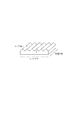
プリズム部材は複数の三角柱状の単位プリズムの長軸方向が互いに平行になるように配置されたプリズム部材である。具体的には、図3に示すような部材であって、単位プリズムとは、プリズム部材の山1つ分を指し、長軸方向とは三角柱の軸方向のことを指す。 The prism member is a prism member arranged such that the major axis directions of a plurality of triangular prism unit prisms are parallel to each other. Specifically, in the member shown in FIG. 3, the unit prism refers to one peak of the prism member, and the major axis direction refers to the axial direction of the triangular prism.
そして、本発明において、偏光部材はプリズム部材よりも光取り出し側に配置されていて、プリズム部材の頂角が90度以上140度以下である。頂角とは図3に示すθのことである。偏光部材をプリズム部材よりも光取り出し側に配置すること、及びプリズム部材の頂角を上記数値範囲内にすることによって、プリズム部材の表面で反射した光が偏光部材によって外部に取り出されなくなり、外光反射の低減ができるのである。 And in this invention, the polarizing member is arrange | positioned rather than the prism member at the light extraction side, and the vertex angle of a prism member is 90 to 140 degree | times. The apex angle is θ shown in FIG. By disposing the polarizing member closer to the light extraction side than the prism member, and setting the apex angle of the prism member within the above numerical range, the light reflected by the surface of the prism member is not extracted to the outside by the polarizing member. Light reflection can be reduced.
以下、図面に基づいて本発明の実施形態について説明する。 Hereinafter, embodiments of the present invention will be described with reference to the drawings.
図1(a)は、本発明にかかる有機EL発光装置の一実施形態を示す図である。10は有機EL素子、11は円偏光部材、12はプリズム部材である。本実施形態は、光取り出し側から、偏光部材、位相差部材、プリズム部材、有機EL素子の順に配置される構成についての実施形態である。 FIG. 1A is a diagram showing an embodiment of an organic EL light emitting device according to the present invention. 10 is an organic EL element, 11 is a circularly polarizing member, and 12 is a prism member. This embodiment is an embodiment of a configuration in which a polarizing member, a retardation member, a prism member, and an organic EL element are arranged in this order from the light extraction side.
有機EL素子10からの発光は、プリズム部材12を透過中にプリズム面で屈折され、正面方向へ集光された後、円偏光部材11を透過して、観察方向へ取り出される。 Light emitted from the organic EL element 10 is refracted by the prism surface while being transmitted through the prism member 12, condensed in the front direction, and then transmitted through the circular polarization member 11 and extracted in the observation direction.
一方、パネル外から入射した外光は円偏光部材11を通過する。円偏光成分はプリズム部材12を透過後、有機EL素子10の反射電極で、反射される。反射時に円偏光の回転方向が反転する。この反射光はプリズム部材12を透過後、円偏光部材11に入射するが、回転方向が反転した円偏光成分は吸収されてしまい、最終的に発光装置の外から入射した外光は、観察方向へは取り出されず、外光反射を低減する効果を示す。 On the other hand, external light incident from the outside of the panel passes through the circularly polarizing member 11. The circularly polarized light component is reflected by the reflective electrode of the organic EL element 10 after passing through the prism member 12. When reflected, the direction of rotation of circularly polarized light is reversed. This reflected light is transmitted through the prism member 12 and then enters the circularly polarizing member 11. However, the circularly polarized component whose rotation direction is reversed is absorbed, and the external light finally incident from the outside of the light emitting device is in the observation direction. The effect of reducing external light reflection is not shown.
また、図1(b)は、本発明にかかる有機EL発光装置の別の実施形態を示す図である。13は偏光部材、14は位相差部材である。本実施形態は、光取り出し側から、偏光部材、プリズム部材、位相差部材、有機EL素子の順に配置される構成についての実施形態である。 FIG. 1B is a diagram showing another embodiment of the organic EL light emitting device according to the present invention. 13 is a polarizing member, and 14 is a phase difference member. This embodiment is an embodiment of a configuration in which a polarizing member, a prism member, a retardation member, and an organic EL element are arranged in this order from the light extraction side.
この場合は有機EL素子からの発光は、位相差部材14、プリズム部材12を透過中にプリズム面で屈折され、正面方向へ集光された後、偏光部材13を透過して、観察方向へ取り出される。一方、パネル外から入射した外光は偏光部材13を通過する。偏光成分はプリズム部材12、位相差部材14を透過後円偏光となり、有機EL素子10の反射電極で、反射される。反射時に円偏光の回転方向が反転する。この反射光は位相差部材14、プリズム部材12を透過後90度回転した直線偏光となる。この反射光は偏光部材13に入射するが、90度回転した直線偏光成分は吸収されてしまい、最終的にパネル外から入射した外光は、観察方向へは取り出されず、外光反射を低減する効果を示す。 In this case, light emitted from the organic EL element is refracted by the prism surface while being transmitted through the retardation member 14 and the prism member 12, condensed in the front direction, and then transmitted through the polarizing member 13 and taken out in the observation direction. It is. On the other hand, external light incident from the outside of the panel passes through the polarizing member 13. The polarized component becomes circularly polarized light after passing through the prism member 12 and the phase difference member 14, and is reflected by the reflective electrode of the organic EL element 10. When reflected, the direction of rotation of circularly polarized light is reversed. The reflected light becomes linearly polarized light that is rotated 90 degrees after passing through the phase difference member 14 and the prism member 12. Although this reflected light is incident on the polarizing member 13, the linearly polarized light component rotated by 90 degrees is absorbed, and the external light finally incident from the outside of the panel is not taken out in the observation direction, reducing external light reflection. Show the effect.
以上のようにプリズム部材12を透過する光については外光反射を低減する効果を示す。しかし、プリズム部材の表面で反射した光については、必ずしも偏光部材によって吸収されるものではないことを本発明者は発見した。つまり、後述するように、外光の入射方向、及びプリズムの頂角によっては、プリズム部材の表面で反射した光が偏光部材を透過して外部に出てしまう場合があるのである。
次に、本発明にかかる有機EL発光装置を構成する各部材について説明する。
As described above, the light transmitted through the prism member 12 has an effect of reducing external light reflection. However, the present inventor has discovered that the light reflected by the surface of the prism member is not necessarily absorbed by the polarizing member. That is, as will be described later, depending on the incident direction of external light and the apex angle of the prism, the light reflected by the surface of the prism member may pass through the polarizing member and exit to the outside.
Next, each member which comprises the organic EL light-emitting device concerning this invention is demonstrated.
[プリズム部材]
プリズム部材は有機EL素子の光取り出し面と接する面の反対側に凸部が複数設けられた光透過性を有する部材である。本発明における凸部の形状は、複数の三角柱状の単位プリズムの長軸方向が互いに平行になるように配置された形状である。
[Prism member]
The prism member is a light-transmitting member in which a plurality of convex portions are provided on the side opposite to the surface in contact with the light extraction surface of the organic EL element. The shape of the convex part in this invention is a shape arrange | positioned so that the major axis direction of a some triangular prism unit prism may become mutually parallel.
三角柱形状は、バックライトの輝度上昇フィルムとしてすでに商品化されていることもあり、低コストで導入できるという利点がある。 The triangular prism shape has already been commercialized as a brightness enhancement film of a backlight, and has an advantage that it can be introduced at a low cost.
凸部の高さ、底面の形状は最適化され、凸部面の傾斜が所定の角度に近くなるように、三角柱が敷き詰められていることが好ましい。底辺が、1μm〜100μm、高さが0.1μm〜200μm程度に設定されることが好ましい。 It is preferable that the height of the convex portion and the shape of the bottom surface are optimized, and the triangular prisms are spread so that the inclination of the convex portion surface is close to a predetermined angle. It is preferable that the base is set to about 1 μm to 100 μm and the height is set to about 0.1 μm to 200 μm.
凸部形状で、回折の影響で部材が色味を帯びないようにするには、1μ以上のピッチサイズが好ましい。またパネル観察する際画像の滲みを感じないためには、画素ピッチを越えないサイズ(通常100μ程度)が好ましい。 A pitch size of 1 μm or more is preferable in order to prevent the member from being tinted due to the influence of diffraction in the convex shape. Further, in order not to feel image blur when observing the panel, a size not exceeding the pixel pitch (usually about 100 μm) is preferable.
部材を作製するには、透明シートを用いて凸パターンを形成する。シート材料としては、ポリメタクリル酸メチル(PMMA)、ポリカーボネート(PC)、セルローストリアセテート(TAC)、ガラスなどを用いることができる。屈折率はそれぞれ1.49〜1.57で、ほぼ同じ値である。 In order to produce a member, a convex pattern is formed using a transparent sheet. As the sheet material, polymethyl methacrylate (PMMA), polycarbonate (PC), cellulose triacetate (TAC), glass or the like can be used. Refractive indexes are 1.49 to 1.57, which are almost the same values.
外光反射防止のため円偏光部材をプリズム部材の発光取り出し側に設ける場合は特に材料の複屈折の少ないシート材料を選ぶことが好ましい。 In order to prevent reflection of external light, it is preferable to select a sheet material having a small birefringence of the material, particularly when the circularly polarizing member is provided on the light emission extraction side of the prism member.
凸部の形成は、まずフォトリソグラフィ技術を用いてレジスト凸パターンを形成し、電鋳技術を用いてパターン転写した凹金型を作製する。次にこの凹金型を用いて上記透明シートを加熱圧縮成形して凸部パターンを得る。あるいは光硬化性樹脂を用いてシート上に凸パターンを転写した後、この光硬化性樹脂を紫外線硬化するなどの工程により凸パターンを形成する。 For the formation of the convex portion, first, a resist convex pattern is formed by using a photolithography technique, and a concave mold in which the pattern is transferred by using an electroforming technique is produced. Next, the convex sheet pattern is obtained by heat compression molding the transparent sheet using the concave mold. Or after transferring a convex pattern on a sheet | seat using a photocurable resin, a convex pattern is formed by processes, such as ultraviolet-curing this photocurable resin.
液晶用バックライトの輝度上昇フィルムなどとして用いられる三角柱凸パターンシートを作製するには、シリンダーの金型が用いられる場合がある。銅メッキなどで表面平坦処理をしたシリンダーを回転させて、ダイヤモンドバイトなどで所定の溝凹パターンを切削形成する。次にこのシリンダーを用いて印刷の要領で、凸パターンを形成する。すなわちシリンダーの凹溝部に光硬化性樹脂を含ませ、シリンダーを回転させながら、透明シート面に光硬化性樹脂による凸部パターンを転写する。次に紫外線照射により凸部パターンを硬化する。この方式では透明シート部材の厚さを数μmまで薄くしても良好な凸部パターン形状が得られ、金型の作製、プリズム部材作製ともに低コストで行える利点がある。 In order to produce a triangular prism convex pattern sheet used as a brightness enhancement film for a liquid crystal backlight, a cylinder mold may be used. A cylinder subjected to surface flattening with copper plating or the like is rotated, and a predetermined groove / concave pattern is formed by cutting with a diamond tool or the like. Next, using this cylinder, a convex pattern is formed in the manner of printing. That is, a photocurable resin is included in the concave groove portion of the cylinder, and the convex pattern of the photocurable resin is transferred to the transparent sheet surface while rotating the cylinder. Next, the convex pattern is cured by ultraviolet irradiation. In this method, even when the thickness of the transparent sheet member is reduced to several μm, a good convex pattern shape can be obtained, and there is an advantage that both the mold fabrication and the prism member fabrication can be performed at low cost.
[偏光部材(直線偏光部材)]
偏光部材はあらゆる方向に振動している光から一定方向にのみ振動する直線偏光を取り出すフィルターである。例えば一軸に延伸されたポリビニルアルコールフィルムにヨウ素などのニ色性色素を吸着配向させたものが使用される。
[Polarizing member (linearly polarizing member)]
The polarizing member is a filter that extracts linearly polarized light that oscillates only in a certain direction from light oscillating in all directions. For example, a film obtained by adsorbing and orienting a dichroic dye such as iodine on a uniaxially stretched polyvinyl alcohol film is used.
[位相差部材(λ/4位相部材)]
位相差部材は偏光部材によって偏光状態になった光に位相差を与える。本発明ではほぼλ/4の位相差を与え、直線偏光を円偏光に、円偏光を直線偏光に、それぞれ偏光状態を変える働きをもつ。材料としては、例えばポリカーボネートの一軸延伸配向フィルムなどが用いられる。
[Phase difference member (λ / 4 phase member)]
The phase difference member gives a phase difference to the light polarized by the polarizing member. In the present invention, a phase difference of approximately λ / 4 is given, and the polarization state is changed to circularly polarized light and circularly polarized light to linearly polarized light, respectively. As the material, for example, a uniaxially stretched oriented film of polycarbonate or the like is used.
[円偏光部材]
上記の偏光部材と位相差部材とを積層したものである。本発明においては、光取り出し側に偏光部材が配置される。円偏光部材を透過する光は、円偏光に変換される。また円偏光部材を透過する円偏光は位相差部材を透過する際に直線偏光に変換される。一度この円偏光部材を透過して、反射した円偏光は再度この円偏光部材を透過する際は偏光部材と直交する向きの偏光に変換されるため、偏光部材で吸収されて透過することはできない。
[Circularly polarizing member]
The polarizing member and the retardation member are laminated. In the present invention, a polarizing member is disposed on the light extraction side. Light that passes through the circularly polarizing member is converted into circularly polarized light. The circularly polarized light that passes through the circularly polarizing member is converted into linearly polarized light when it passes through the phase difference member. Once the circularly polarized light that has been transmitted through this circularly polarizing member and reflected again is converted into polarized light in a direction orthogonal to the polarizing member when transmitted through this circularly polarizing member again, it cannot be absorbed and transmitted by the polarizing member. .
[有機EL素子]
有機EL素子は、公知の素子構成、素子材料を適宜利用することができる。
[Organic EL device]
As the organic EL element, a known element configuration and element material can be appropriately used.
図2はトップエミッション有機EL素子の構造例を示す断面図である。駆動用回路などがあらかじめ設けられた基板21に真空蒸着法で正孔輸送層や発光層、電子輸送層等の有機EL膜を形成する。 FIG. 2 is a cross-sectional view showing a structural example of a top emission organic EL element. An organic EL film such as a hole transport layer, a light-emitting layer, and an electron transport layer is formed on a substrate 21 provided with a drive circuit and the like by a vacuum deposition method.
基板21にはあらかじめ50nmの厚さ、100μ□のCrの金属アノード電極22が、200μピッチで2次元パターン形成されている。アノード電極材料としては他に反射率の高いAl,Agなどでも良く、正孔注入性を高めるために、ITO,IZOなどの透明導電膜をこの上に積層することも可能である。 The substrate 21 is preliminarily formed with a two-dimensional pattern having a thickness of 50 nm and a 100 μ □ Cr metal anode electrode 22 at a pitch of 200 μm. As the anode electrode material, Al, Ag, or the like having high reflectivity may be used, and a transparent conductive film such as ITO or IZO can be laminated thereon in order to improve the hole injection property.
最初に有機EL材料である正孔輸送層23として、α−NPDを20nmの厚さに積層、次に発光層24としてAlq3を30nmの厚さに積層、次に電子注入層25として炭酸セシウムと Alq3の混合膜を50nmの厚さに積層した。 First, α-NPD is laminated to a thickness of 20 nm as a hole transport layer 23 which is an organic EL material, then Alq3 is laminated to a thickness of 30 nm as a light emitting layer 24, and then cesium carbonate as an electron injection layer 25. A mixed film of Alq3 was laminated to a thickness of 50 nm.
次に透明カソード電極26としてITO膜をスパッタ法により60nmの厚さに積層し有機EL素子を形成した。 Next, an ITO film was laminated as a transparent cathode electrode 26 to a thickness of 60 nm by sputtering to form an organic EL element.
またこの素子構成では、Alq3分子のEL発光は、正孔輸送層23とAlq3発光層24の界面で起こることが知られている。 In this element configuration, it is known that EL emission of Alq3 molecules occurs at the interface between the hole transport layer 23 and the Alq3 light emitting layer 24.
外部から水分が有機EL膜に浸透しないように、透明保護膜27としてSiN膜をスパッタ法により640nmの厚さに積層して、有機EL素子を完成した。 In order to prevent moisture from permeating the organic EL film from the outside, a SiN film as a transparent protective film 27 was laminated to a thickness of 640 nm by sputtering to complete an organic EL element.
透明保護膜としては、例えば特開平11−97169号公報でケイ素、ホウ素、ゲルマニウム、などを主成分とした酸化物、窒化物、硫化物材料の膜が適していることが開示されている。酸素、水分などの遮断効果が得られる膜厚は300nm〜10μmほどである。膜応力を小さくすること、成膜時間を短くして生産性を高めることを考えると、好ましくは300nm〜5μm程度が望ましい。
次に、本発明の規定するプリズムの頂角について説明する。
As the transparent protective film, for example, Japanese Patent Application Laid-Open No. 11-97169 discloses that an oxide, nitride, or sulfide material film mainly containing silicon, boron, germanium, or the like is suitable. The film thickness for obtaining the blocking effect of oxygen, moisture, etc. is about 300 nm to 10 μm. In consideration of reducing the film stress and increasing the productivity by shortening the film formation time, it is preferably about 300 nm to 5 μm.
Next, the apex angle of the prism defined by the present invention will be described.
<光取り出し効率向上について>
プリズムの頂角を変化させた時の、EL発光の光取り出し効率を算出するために、市販の光線追跡シミュレーションソフトを用いた。光線追跡シミュレーション条件は以下のように設定した。
<About improving light extraction efficiency>
In order to calculate the light extraction efficiency of EL emission when the apex angle of the prism is changed, commercially available ray tracing simulation software was used. Ray tracing simulation conditions were set as follows.
(1)発光の設定
EL発光:発光層の中心平面より完全拡散発光
光線本数:2000本 モンテカルロシミュレーション
フレネル分岐数:50
(2)構成系のパラメーターの設定
アノード電極:完全反射
発光層:屈折率1.70 膜厚0.13μm
カソード電極:ITO 屈折率2.00 膜厚0.05μm
保護層: 屈折率1.53 膜厚50.0μm
プリズム:屈折率1.53 頂角20〜160度 ピッチ幅20μm
端面フレネル反射
(1) Setting of light emission EL light emission: Number of completely diffused light rays from the central plane of the light emitting layer: 2000 Monte Carlo simulation Number of Fresnel branches: 50
(2) Setting of system parameters Anode electrode: Complete reflection light emitting layer: Refractive index 1.70 Film thickness 0.13 μm
Cathode electrode: ITO Refractive index 2.00 Film thickness 0.05μm
Protective layer: Refractive index 1.53 Film thickness 50.0 μm
Prism: Refractive index 1.53 Apex angle 20 to 160 degrees Pitch width 20 μm
End face Fresnel reflection
ここで、光取り出し効率は、発光させた全光束に対する、EL素子最上面(保護層またはプリズム)を通過して素子の外部へ向かう光束との比を求めることによって算出した。プリズムなしの系を平坦系として比較例とした。 Here, the light extraction efficiency was calculated by determining the ratio of the total luminous flux emitted to the luminous flux passing through the EL element uppermost surface (protective layer or prism) and going to the outside of the element. A system without a prism was used as a comparative example as a flat system.
表1に、プリズムの頂角を20度から160度まで変化させた時の、光取り出し効率のシミュレーション結果を示す。 Table 1 shows a simulation result of the light extraction efficiency when the apex angle of the prism is changed from 20 degrees to 160 degrees.
光取り出し効率は、平坦系の値に比べて約2倍弱、増大しているが、140度を越えると、平坦系の特性に近づいていく。そこで、光取り出し効率を向上させる観点から、プリズムの頂角としては60度以上140度以下が好ましいことがわかる。 The light extraction efficiency is increased by a little less than about twice that of the flat system value. However, when it exceeds 140 degrees, the light extraction efficiency approaches the characteristics of the flat system. Therefore, it is understood that the vertical angle of the prism is preferably 60 degrees or more and 140 degrees or less from the viewpoint of improving the light extraction efficiency.
<外光反射防止について>
次に外光反射防止について考察する。上述したようにプリズム部材が単に光を透過させるだけなら、円偏光部材との組み合わせにより外光反射を防止することができる。
<About anti-light reflection>
Next, the prevention of external light reflection will be considered. As described above, if the prism member simply transmits light, the reflection with external light can be prevented by the combination with the circularly polarizing member.
しかし、以下の要因をふまえて考察する必要がある。
(1)プリズム面への外光入射は、プリズム面に凹凸があることによって、プリズム面を基準とした時の入射角に依存して挙動が異なることを考慮する必要がある。
(2)また、入射角が大きくなると(後述するように、55度以上で)位相反転が起こることも考慮する必要がある。
(3)さらに、プリズム部材内で反射する回数に依存して位相反転の有無も異なってくることも考慮する必要がある。
However, it is necessary to consider the following factors.
(1) It is necessary to consider that the behavior of external light incident on the prism surface varies depending on the incident angle when the prism surface is used as a reference due to the unevenness of the prism surface.
(2) It is also necessary to consider that phase inversion occurs when the incident angle is large (at 55 degrees or more as will be described later).
(3) Furthermore, it is necessary to consider that the presence or absence of phase inversion varies depending on the number of reflections in the prism member.
以上より、外光反射防止の効果は、外光の入射角、位相反転の有無によって異なってくる。 As described above, the effect of preventing external light reflection varies depending on the incident angle of external light and the presence or absence of phase inversion.
表2に空気層と接するプリズム部材を想定して、自然光の外光が空気層から屈折率1.5の平面層に入射する際の、入射角度に対する自然光とP偏光の反射率、及び夫々の反射時の位相変化を計算した結果を示す。ここで自然光の反射率は、P偏光とS偏光夫々の反射率の平均値である。 Assuming the prism member in contact with the air layer in Table 2, the reflectance of the natural light and the P-polarized light with respect to the incident angle when the external light of the natural light is incident on the plane layer having a refractive index of 1.5 from the air layer, and The calculation result of the phase change at the time of reflection is shown. Here, the reflectance of natural light is an average value of the reflectance of each of the P-polarized light and the S-polarized light.
入射角が大きい、斜め方向の入射になるとP偏光、自然光ともに反射率が高くなる傾向を示すが、P偏光は自然光に比べて反射率の上昇が小さいので、プリズム部材での反射を抑えるため、P偏光を選択するのが好ましい。ちなみにP偏光では入射角度65度まで反射率は3%以下である。 When the incident angle is large and the incident angle is oblique, the reflectance of both P-polarized light and natural light tends to increase. However, since the increase in reflectance of P-polarized light is smaller than that of natural light, in order to suppress reflection at the prism member, P-polarized light is preferably selected. Incidentally, with P-polarized light, the reflectance is 3% or less up to an incident angle of 65 degrees.
このような反射率の入射角依存性は、たとえば、「応用光学」鶴田匡夫 培風館、1990、p35などに示されている。以下で示すように入射角55度を境にして位相反転が生じていることに留意する必要がある。 Such dependency of the reflectance on the incident angle is shown, for example, in “Applied Optics” Tatsuo Tatsuo Baifukan, 1990, p35. As shown below, it should be noted that phase inversion occurs at an incident angle of 55 degrees.
図1(b)の構成では、パネル外から入射した入射角55度以下の外光の場合、直線偏光板を通過し、その後プリズム部材表面で反射した光は、直線偏光板を透過して表示パネル外に出てしまうので、EL発光と重なり映り込みが起こり、表示品質が低下する。 In the configuration of FIG. 1B, in the case of outside light incident from the outside of the panel and having an incident angle of 55 degrees or less, the light that has passed through the linear polarizing plate and then reflected by the prism member surface is transmitted through the linear polarizing plate and displayed. Since it goes out of the panel, it overlaps with the EL emission and the display quality deteriorates.
入射角55度以上の外光の場合は、プリズム部材表面での反射時に位相反転が起こるので、直線偏光板で吸収され外光反射は起こらない。この場合は、プリズム部材/空気界面の反射は全ての入射角度で3%以内であり、さらに反射防止(AR)コート処理をすれば1%以内にすることも容易である。 In the case of outside light having an incident angle of 55 degrees or more, phase inversion occurs when reflecting on the prism member surface, and therefore, it is absorbed by the linear polarizing plate and does not reflect outside light. In this case, the reflection at the prism member / air interface is within 3% at all incident angles, and it is easy to make the reflection within 1% if anti-reflection (AR) coating is applied.
以上の考察からわかるように、外光反射防止の効果は外光の入射角や位相反転挙動によって異なってくる。 As can be seen from the above consideration, the effect of preventing external light reflection varies depending on the incident angle and phase inversion behavior of external light.
さらに、プリズム面で複数回反射が起こる場合の位相反転も考慮する必要がある。 Furthermore, it is necessary to consider phase reversal when reflection occurs multiple times on the prism surface.
外光が直線偏光板を通過して、外光の偏光成分は部材のプリズム面に入射する。外光の入射角度は、プリズム面が傾斜しているので、重畳されて大きな角度になる。例えば頂角60度のプリズム面に、正面方向から入射する外光は実効的には斜め60度入射になり、プリズム面で複数回反射して、外光反射として観察される。とくにプリズムの頂角が60度より小さなものは、複数回反射が多くなり、外光反射が大きくなる。 External light passes through the linear polarizing plate, and the polarization component of the external light enters the prism surface of the member. Since the prism surface is inclined, the incident angle of the external light is superimposed and becomes a large angle. For example, external light incident on the prism surface having an apex angle of 60 degrees from the front direction is effectively incident at an oblique angle of 60 degrees, reflected multiple times on the prism surface, and observed as external light reflection. In particular, when the apex angle of the prism is smaller than 60 degrees, the reflection is increased a plurality of times and the reflection of external light is increased.
また、P偏光では55度以下の入射角度では位相変化が起こらないが、55度以上の入射角度では位相反転する。例えばP偏光が55度以上の入射角度で偶数回反射した時、反射光は偏光板で吸収されず反射外光となる。 Further, with P-polarized light, no phase change occurs at an incident angle of 55 degrees or less, but phase inversion occurs at an incident angle of 55 degrees or more. For example, when P-polarized light is reflected an even number of times at an incident angle of 55 degrees or more, the reflected light is not absorbed by the polarizing plate but becomes reflected external light.
以上の考察により、外光がプリズム面で2回以上反射してしまうと、図1(b)の構成系での十分な外光反射防止効果が得られないことがわかる。図1(a)についても同様な結果となる。 From the above considerations, it can be seen that if the external light is reflected twice or more on the prism surface, a sufficient effect of preventing external light reflection in the system shown in FIG. 1B cannot be obtained. Similar results are obtained with respect to FIG.
このように複数回反射が起こる場合は、複雑な位相変化があるので、光線追跡法によるシミュレーション予測が有効で、実際に外光反射の状態を確認することが必要である。 When reflection occurs multiple times in this way, there is a complicated phase change, so that simulation prediction by the ray tracing method is effective, and it is necessary to actually check the state of external light reflection.
前述の市販ソフトを用いた光線追跡法により、外光の入射角度を変えながら、プリズムの頂角を変えた時の反射光の角度および複数回の反射があるかどうかを調べた。複数回の反射があり、反射時の入射角度が55度より大きいものは×、複数回の反射が無く、反射時の入射角度が55度より小さいものは○とした。特定の外光入射角度(正面)でのみ2回反射がある(このときは反射時の入射角度は55度以下)場合は△の評価を与えた。 By the ray tracing method using the above-mentioned commercially available software, the angle of reflected light when the apex angle of the prism was changed while the incident angle of external light was changed and whether there were multiple reflections were investigated. The case where there was a plurality of reflections and the incident angle at the time of reflection was larger than 55 degrees was evaluated as x, and the case where there was no multiple times of reflection and the incident angle at the time of reflection was smaller than 55 degrees was marked as ◯. When there was reflection twice only at a specific external light incident angle (front) (in this case, the incident angle at the time of reflection is 55 degrees or less), an evaluation of Δ was given.
表3に、結果を示す。プリズムの頂角60度以下では、ほとんどの外光入射角度で複数回の反射があり、外光反射防止効果は期待できない。プリズムの頂角90度から120度までは正面方向からの外光入射でわずかに2回反射が起こる場合がある。プリズムの頂角130度以上では1回反射だけで、反射時の入射角度も55度以下であり、良好な反射防止効果が期待できる。 Table 3 shows the results. When the apex angle of the prism is 60 degrees or less, there is a plurality of reflections at almost all external light incident angles, and an external light antireflection effect cannot be expected. When the apex angle of the prism is 90 to 120 degrees, reflection may occur slightly twice due to external light incident from the front direction. When the apex angle of the prism is 130 degrees or more, only one reflection is performed, and the incident angle at the time of reflection is 55 degrees or less, and a good antireflection effect can be expected.
図4と図5に、シミュレーション例を示す。
図4は評価×の例である。プリズムの頂角45度、外光15度入射条件では、複数回の多重反射がほとんどである。図5は評価○の例である。プリズムの頂角140度、外光15度入射条件では、1回反射のみでプリズム面への入射角度は5度と55度であった。
4 and 5 show simulation examples.
FIG. 4 is an example of evaluation x. Under the condition that the prism has an apex angle of 45 degrees and an external light incident angle of 15 degrees, multiple reflections are mostly performed. FIG. 5 shows an example of evaluation ○. Under the incident conditions of the prism apex angle of 140 degrees and external light of 15 degrees, the incident angles on the prism surface were 5 degrees and 55 degrees with only one reflection.
以上の考察とシミュレーションにより、プリズムの頂角を90度以上とすれば、外光反射を低減することができる。 From the above consideration and simulation, if the apex angle of the prism is 90 degrees or more, external light reflection can be reduced.
以上より、光取り出し効率向上をしつつ外光反射低減をするためには、プリズムの頂角が90度以上140度以下とすることが好ましいことが分かった。 From the above, it was found that the apex angle of the prism is preferably 90 degrees or more and 140 degrees or less in order to reduce external light reflection while improving the light extraction efficiency.
以下、実施例を挙げて本発明をより詳細に説明する。 Hereinafter, the present invention will be described in more detail with reference to examples.
(実施例1(光取り出し効率について))
プリズム部材を付加した有機EL発光装置を以下の手順で作製した。
(Example 1 (about light extraction efficiency))
An organic EL light emitting device to which a prism member was added was produced by the following procedure.
まず、図1(a)の構成の素子を作成した。頂角110度、ピッチ15μの三角柱プリズムパターンを光学等方フィルム(厚さ70μシート)上に、アクリル系光硬化性樹脂を転写、紫外線硬化により成形した。これがプリズム部材に相当する。さらに円偏光板(サンリッツ製 製品コードRD−HL56−W03 厚さ100μシート)を用意した。
First, an element having the configuration shown in FIG. A triangular prism prism pattern having an apex angle of 110 degrees and a pitch of 15 μ was formed on an optically isotropic film (70 μm thick sheet) by transferring an acrylic photocurable resin and ultraviolet curing. This corresponds to a prism member. Furthermore, a circularly polarizing plate (product code RD-HL56-
有機EL素子と上記プリズム部材、円偏光部材を貼りあわせることで本発明の装置が完成する。これを貼りあわせ部材1とする。
The apparatus of the present invention is completed by bonding the organic EL element, the prism member and the circularly polarizing member. This is referred to as a
次に、図1(b)の構成の有機EL発光装置を作成した。頂角110度、ピッチ15μの三角柱プリズムパターンを逆波長分散λ/4位相板(共重合ポリカーボネートフィルム 厚さ70μシート)上に、アクリル系光硬化性樹脂を転写、紫外線硬化により成形した。これがプリズム部材および位相差部材に相当する。さらに、直線偏光板(サンリッツ製 製品コードLLC2−82−18 厚さ100μシート)を用意した。次に、有機EL素子と上記逆波長分散λ/4位相板、直線偏光板とを貼りあわせることで本発明の装置が完成する。これを貼りあわせ部材2とする。 Next, an organic EL light emitting device having the configuration shown in FIG. A triangular prism prism pattern having an apex angle of 110 degrees and a pitch of 15 μm was formed on an inverse wavelength dispersion λ / 4 phase plate (copolymerized polycarbonate film 70 μm thick sheet) by transferring acrylic photo-curing resin and ultraviolet curing. This corresponds to a prism member and a phase difference member. Furthermore, a linear polarizing plate (product code LLC2-82-18 100 μm thick sheet manufactured by Sanlitz) was prepared. Next, the apparatus of the present invention is completed by laminating the organic EL element, the above-mentioned inverse wavelength dispersion λ / 4 phase plate, and the linear polarizing plate. This is referred to as a bonding member 2.
次の方向に重ねることが好ましい。つまり、本発明の有機EL発光装置を表示装置に適用させる場合において、主たる観察方向が決まっている場合、プリズム部材の長軸方向とパネルの横方向がおおむね一致するように貼り合わせることが好ましい。通常、横長パネルの場合は正面から見て長い方向を横位置として観察するためである。こうするとパネルを横方向、斜めから観察しても輝度の低下が少ない。 It is preferable to overlap in the following direction. That is, when the organic EL light emitting device of the present invention is applied to a display device, when the main observation direction is determined, it is preferable that the long axis direction of the prism member and the horizontal direction of the panel are bonded to each other. Usually, in the case of a horizontally long panel, a long direction as viewed from the front is observed as a horizontal position. In this way, there is little decrease in luminance even when the panel is observed laterally or obliquely.
また、偏光部材の延伸方向とプリズム部材の長軸方向がほぼ直交するように、張り合わせることが好ましい。こうすると重ねたとき外光が反射したときに干渉縞が現れることがない。 Further, it is preferable that the polarizing members are bonded so that the extending direction of the polarizing member and the major axis direction of the prism member are substantially orthogonal to each other. This prevents interference fringes from appearing when external light is reflected when they are stacked.
一方、有機EL素子と上記円偏光部材のみを貼りあわせたものをref−1とする。 On the other hand, a combination of only the organic EL element and the circularly polarizing member is referred to as ref-1.
本実施例では、頂角110度のプリズム面が設けられているため、従来の平面では全反射で取り出されない光を含めて、垂直方向へ出射される光の成分が多くなる。 In this embodiment, since the prism surface having an apex angle of 110 degrees is provided, the light components emitted in the vertical direction increase including light that is not extracted by total reflection in the conventional plane.
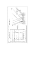
図6に、輝度計を用いて測定した頂角110度プリズム部材を貼りあわせた有機EL素子の、発光強度の放射角度依存性を示した。有機EL素子に頂角110度のプリズム部材を重ねたものは、貼りあわせ部材1、2共に、ref−1に比べて正面の発光強度は約1.4倍に増加していることがわかる。ここで正面方向を放射角度0度とした。
FIG. 6 shows the radiation angle dependency of the emission intensity of an organic EL element in which a prism member having an apex angle of 110 degrees measured using a luminance meter is bonded. It can be seen that when the prism member having an apex angle of 110 degrees is superimposed on the organic EL element, the light emission intensity on the front surface of both the
表5に、プリズムの頂角を20度から170度まで変化させた時の、正面方向での発光強度の角度依存を調べた結果を示す。正面強度比はプリズムなしの平坦な素子(ref−1)との比である。 Table 5 shows the results of examining the angle dependence of the light emission intensity in the front direction when the apex angle of the prism is changed from 20 degrees to 170 degrees. The front intensity ratio is a ratio with a flat element (ref-1) without a prism.
50度より大きな頂角では、正面方向の発光強度が増大するが、120度を越えると斜め方向の発光強度の低下がある。150度を越えると、ref−1の特性に近づいていく。 When the apex angle is greater than 50 degrees, the light emission intensity in the front direction increases, but when it exceeds 120 degrees, the light emission intensity in the oblique direction decreases. If it exceeds 150 degrees, it will approach the characteristics of ref-1.
そこで、光取り出し効率を向上させる観点から、プリズムの頂角としては正面方向へ出射される光の成分が、ref−1より大きくなる50度以上140度以下が好ましいことが分かった。 Therefore, it has been found that from the viewpoint of improving the light extraction efficiency, the apex angle of the prism is preferably 50 degrees or more and 140 degrees or less where the light component emitted in the front direction is larger than ref-1.
(実施例2(外光反射防止について))
外光反射の影響を評価するために、ガラス基板にAlを蒸着した基板を用意した。それぞれ頂角の異なるプリズム部材をアクリル樹脂で接着し、この上に円偏光板を設けた。これらのサンプルを村上色彩技術研究所(株)製「3次元変角分光測色システム GCMS−11」で外光反射の影響を観察、評価した。具体的には標準白色光源(キセノンランプ)のほぼ平行光線を入射角度を変えながらサンプルに照射して、サンプル面を観察した。
(Example 2 (For preventing external light reflection))
In order to evaluate the influence of external light reflection, a substrate was prepared by depositing Al on a glass substrate. Prism members having different apex angles were bonded with acrylic resin, and a circularly polarizing plate was provided thereon. These samples were observed and evaluated for the influence of external light reflection by “3D variable angle spectrocolor measurement system GCMS-11” manufactured by Murakami Color Research Laboratory Co., Ltd. Specifically, the sample surface was observed by irradiating the sample with substantially parallel light from a standard white light source (xenon lamp) while changing the incident angle.
表4に、この結果を示す。正面および斜め方向から観察して真っ黒に見えるもの(外光反射防止効果があるもの)は、○、プリズム部材面からの反射で白っぽく見えるものは×、プリズム部材の反射が注意すると見えるものは△で評価した。 Table 4 shows the results. Observed from the front and diagonal directions, and those that appear black (with an effect of preventing reflection of external light) are ○, those that appear whitish by reflection from the prism member surface, and those that appear when the reflection of the prism member is careful △ It was evaluated with.
さらに同様に、外光反射の影響を評価するために、ガラス基板にAlを蒸着した基板を用意した。それぞれ頂角の異なるプリズムパターンを逆波長分散λ/4位相板上に成形したシートをアクリル樹脂で接着した。この上に直線偏光板を設けた。これらのサンプルを同様の方法で外光反射の影響を観察し、同様に評価した。 Similarly, in order to evaluate the influence of external light reflection, a substrate was prepared by depositing Al on a glass substrate. A sheet in which prism patterns having different apex angles were formed on a reverse wavelength dispersion λ / 4 phase plate was bonded with an acrylic resin. A linear polarizing plate was provided thereon. These samples were similarly evaluated by observing the influence of external light reflection by the same method.
この結果も表4に加えて示す。
この結果は、表3のシミュレーション予測である、複数回反射で外光反射が大きくなる、という結果とほぼ一致していた。○評価パネルのプリズム部材が見えにくいが、×評価パネルはいずれもプリズム部材が白っぽく見えてしまうことを確認した。特にプリズムの頂角60度以下では、特に顕著に白く見えた。
This result is also shown in addition to Table 4.
This result almost coincided with the result of the simulation prediction in Table 3, in which the reflection of external light is increased by the multiple reflection. ○ Although the prism member of the evaluation panel is difficult to see, it was confirmed that the prism member of each of the x evaluation panels look whitish. In particular, when the apex angle of the prism was 60 degrees or less, it looked particularly white.
また上記サンプルを晴れた屋外で観察したところ、円偏光板を設けたサンプルでは100度以上の頂角のプリズム部材では外光反射防止効果があった。さらに直線偏光板とλ/4位相板を設けたサンプルでは、90度以上の頂角のプリズム部材では外光反射防止効果があることを確認できた。これは表3,4の結果と一致するものであった。 When the sample was observed outdoors in a clear sky, the sample provided with the circularly polarizing plate had the effect of preventing external light reflection with the prism member having an apex angle of 100 degrees or more. Furthermore, in the sample provided with the linearly polarizing plate and the λ / 4 phase plate, it was confirmed that the prism member having the apex angle of 90 degrees or more has the effect of preventing external light reflection. This was consistent with the results in Tables 3 and 4.
このように外光反射防止の観点からはプリズムの頂角は90度以上が好ましい。 Thus, from the viewpoint of preventing reflection of external light, the apex angle of the prism is preferably 90 degrees or more.
上記プリズム部材を通過した、P偏光(λ/4位相板を通過して円偏光となる)あるいは円偏光は、有機EL素子の反射電極で反射される。この反射光は位相が反転することで、直線偏光板あるいは円偏光板に吸収されるので、最終的に入射した外光は反射されず、外光反射防止効果が得られる。 The P-polarized light (passed through the λ / 4 phase plate and becomes circularly polarized light) or circularly polarized light that has passed through the prism member is reflected by the reflective electrode of the organic EL element. The reflected light is absorbed by the linearly polarizing plate or the circularly polarizing plate by inverting the phase, so that the external light finally incident is not reflected, and an external light antireflection effect is obtained.
以上の実施例の結果より、光取り出し効率の向上と外光反射防止を両立できる好ましいプリズムの頂角は、90度以上140度以下となることが分かった。 From the results of the above examples, it was found that the apex angle of a preferable prism capable of achieving both improvement of light extraction efficiency and prevention of reflection of external light is 90 degrees or more and 140 degrees or less.

10 有機EL素子
11 円偏光部材
12 プリズム部材
13 偏光部材
14 位相差部材
21 基板
22 アノード電極
23 正孔輸送層
24 発光層
25 電子輸送層
26 カソード電極
27 透明保護膜
DESCRIPTION OF SYMBOLS 10 Organic EL element 11 Circularly polarizing member 12 Prism member 13 Polarizing member 14 Phase difference member 21 Substrate 22 Anode electrode 23 Hole transport layer 24 Light emitting layer 25 Electron transport layer 26 Cathode electrode 27 Transparent protective film
Claims (7)
前記偏光部材は前記プリズム部材よりも光取り出し側に配置され、
前記プリズム部材の頂角が90度以上140度以下であることを特徴とする有機EL発光装置。 An organic EL light emitting element that emits light in an organic compound layer disposed between a pair of electrodes on a substrate; a prism member, a polarizing member, and a retardation member on a light extraction side of the organic EL light emitting element; In the organic EL light emitting device, the prism member is a prism member arranged so that the major axis directions of a plurality of triangular prism unit prisms are parallel to each other.
The polarizing member is disposed on the light extraction side from the prism member,
An organic EL light-emitting device, wherein the prism member has an apex angle of 90 degrees to 140 degrees.
The organic EL light-emitting device according to claim 1, wherein the light emitted from the organic compound layer is extracted from a side opposite to the substrate.
Priority Applications (2)
| Application Number | Priority Date | Filing Date | Title |
|---|---|---|---|
| JP2006098001A JP2007273275A (en) | 2006-03-31 | 2006-03-31 | Organic el light emitting device |
| US11/683,019 US7683533B2 (en) | 2006-03-31 | 2007-03-07 | Organic electroluminescent device provided with a polarizing plate, a prism member and a phase member in a stacked arrangement |
Applications Claiming Priority (1)
| Application Number | Priority Date | Filing Date | Title |
|---|---|---|---|
| JP2006098001A JP2007273275A (en) | 2006-03-31 | 2006-03-31 | Organic el light emitting device |
Publications (2)
| Publication Number | Publication Date |
|---|---|
| JP2007273275A true JP2007273275A (en) | 2007-10-18 |
| JP2007273275A5 JP2007273275A5 (en) | 2007-11-29 |
Family
ID=38558621
Family Applications (1)
| Application Number | Title | Priority Date | Filing Date |
|---|---|---|---|
| JP2006098001A Pending JP2007273275A (en) | 2006-03-31 | 2006-03-31 | Organic el light emitting device |
Country Status (2)
| Country | Link |
|---|---|
| US (1) | US7683533B2 (en) |
| JP (1) | JP2007273275A (en) |
Cited By (5)
| Publication number | Priority date | Publication date | Assignee | Title |
|---|---|---|---|---|
| WO2009084663A1 (en) | 2007-12-28 | 2009-07-09 | Nippon Shokubai Co., Ltd. | Optical film and image forming apparatus having the same |
| JP2012003074A (en) * | 2010-06-17 | 2012-01-05 | Mitsubishi Rayon Co Ltd | Optical film and optical device using the same |
| KR20140077707A (en) * | 2012-12-14 | 2014-06-24 | 엘지디스플레이 주식회사 | Organic light emitting display device and method for fabricating the same |
| KR20170001634A (en) * | 2015-06-26 | 2017-01-04 | 유니버셜 디스플레이 코포레이션 | Oled devices having improved efficiency |
| KR20180036373A (en) * | 2016-09-30 | 2018-04-09 | 엘지디스플레이 주식회사 | Display device |
Families Citing this family (11)
| Publication number | Priority date | Publication date | Assignee | Title |
|---|---|---|---|---|
| JP4764230B2 (en) * | 2006-03-31 | 2011-08-31 | キヤノン株式会社 | Display device |
| JP2008108705A (en) * | 2006-09-26 | 2008-05-08 | Canon Inc | Organic light-emitting device |
| JP5224835B2 (en) * | 2007-02-09 | 2013-07-03 | 国立大学法人東京工業大学 | ORGANIC EL DEVICE, ITS MANUFACTURING METHOD, AND ORGANIC EL DEVICE EVALUATION METHOD |
| JP2009272193A (en) * | 2008-05-09 | 2009-11-19 | Funai Electric Co Ltd | Backlight apparatus and liquid crystal display device |
| JP4947095B2 (en) * | 2009-06-16 | 2012-06-06 | 住友化学株式会社 | Light extraction structure |
| JP2011100715A (en) * | 2009-10-09 | 2011-05-19 | Canon Inc | Light emitting device, display device, and imaging device |
| US9632326B2 (en) | 2010-10-28 | 2017-04-25 | Philips Lighting Holding B.V. | Collimator comprising a prismatic layer stack, and lighting unit comprising such collimator |
| EP2678719A1 (en) | 2011-02-22 | 2014-01-01 | Koninklijke Philips N.V. | Collimator comprising a prismatic layer stack, and lighting unit comprising such a collimator |
| DE102012204062A1 (en) * | 2012-03-15 | 2013-09-19 | Ledon Oled Lighting Gmbh & Co. Kg | Light output device with an OLED or QLED with improved light output |
| EP3033778A4 (en) | 2013-08-12 | 2017-03-29 | 3M Innovative Properties Company | Emissive article with light extraction film |
| CN104134758A (en) * | 2014-07-14 | 2014-11-05 | 上海和辉光电有限公司 | Structure for packaging OLED display screen |
Citations (9)
| Publication number | Priority date | Publication date | Assignee | Title |
|---|---|---|---|---|
| JPH071428U (en) * | 1993-06-04 | 1995-01-10 | 株式会社エンプラス | Surface light source |
| JPH118063A (en) * | 1997-06-12 | 1999-01-12 | Minnesota Mining & Mfg Co <3M> | Electroluminescence element and manufacture thereof |
| JP2000321431A (en) * | 1999-05-17 | 2000-11-24 | Nitto Denko Corp | Polarizing element, optical element, polarized light source and liquid crystal display device |
| JP2002006776A (en) * | 2000-06-22 | 2002-01-11 | Nec Corp | Image display device |
| JP2004054035A (en) * | 2002-07-22 | 2004-02-19 | Seiko Epson Corp | Liquid crystal display and electronic equipment |
| JP2005091825A (en) * | 2003-09-18 | 2005-04-07 | Nippon Zeon Co Ltd | Polarization separating sheet and luminance raising film |
| JP2006030289A (en) * | 2004-07-12 | 2006-02-02 | Toshiba Matsushita Display Technology Co Ltd | El display device |
| JP2006048011A (en) * | 2004-06-29 | 2006-02-16 | Semiconductor Energy Lab Co Ltd | Display device, its driving method, and electronic equipment |
| JP2006066074A (en) * | 2004-08-24 | 2006-03-09 | Nippon Zeon Co Ltd | Direct backlight device |
Family Cites Families (11)
| Publication number | Priority date | Publication date | Assignee | Title |
|---|---|---|---|---|
| JPH0467016A (en) | 1990-07-05 | 1992-03-03 | Sharp Corp | Liquid crystal display device |
| JPH06308485A (en) | 1993-04-21 | 1994-11-04 | Hitachi Ltd | Display device |
| US6804058B1 (en) * | 1993-12-21 | 2004-10-12 | 3M Innovative Properties Company | Electroluminescent light source and display incorporating same |
| JP3900617B2 (en) | 1997-09-17 | 2007-04-04 | カシオ計算機株式会社 | LIGHT EMITTING ELEMENT AND PROTECTIVE MATERIAL FOR LIGHT EMITTING ELEMENT |
| JP2002216947A (en) | 2001-01-22 | 2002-08-02 | Polatechno Co Ltd | Display device |
| JP2005055481A (en) | 2003-06-09 | 2005-03-03 | Toyota Industries Corp | Optical element, planar illumination apparatus and display apparatus |
| US7420322B2 (en) * | 2003-06-27 | 2008-09-02 | Casio Computer Co., Ltd. | Display device including a flat panel display panel |
| US20050242709A1 (en) * | 2004-04-30 | 2005-11-03 | Seiko Epson Corporation | Display element and method of manufacturing display element |
| US7440044B2 (en) * | 2004-11-29 | 2008-10-21 | Arisawa Manufacturing Co., Ltd. | Color display device and method |
| US8217572B2 (en) * | 2005-10-18 | 2012-07-10 | Semiconductor Energy Laboratory Co., Ltd. | Display device with prism layer |
| JP4764230B2 (en) * | 2006-03-31 | 2011-08-31 | キヤノン株式会社 | Display device |
-
2006
- 2006-03-31 JP JP2006098001A patent/JP2007273275A/en active Pending
-
2007
- 2007-03-07 US US11/683,019 patent/US7683533B2/en not_active Expired - Fee Related
Patent Citations (9)
| Publication number | Priority date | Publication date | Assignee | Title |
|---|---|---|---|---|
| JPH071428U (en) * | 1993-06-04 | 1995-01-10 | 株式会社エンプラス | Surface light source |
| JPH118063A (en) * | 1997-06-12 | 1999-01-12 | Minnesota Mining & Mfg Co <3M> | Electroluminescence element and manufacture thereof |
| JP2000321431A (en) * | 1999-05-17 | 2000-11-24 | Nitto Denko Corp | Polarizing element, optical element, polarized light source and liquid crystal display device |
| JP2002006776A (en) * | 2000-06-22 | 2002-01-11 | Nec Corp | Image display device |
| JP2004054035A (en) * | 2002-07-22 | 2004-02-19 | Seiko Epson Corp | Liquid crystal display and electronic equipment |
| JP2005091825A (en) * | 2003-09-18 | 2005-04-07 | Nippon Zeon Co Ltd | Polarization separating sheet and luminance raising film |
| JP2006048011A (en) * | 2004-06-29 | 2006-02-16 | Semiconductor Energy Lab Co Ltd | Display device, its driving method, and electronic equipment |
| JP2006030289A (en) * | 2004-07-12 | 2006-02-02 | Toshiba Matsushita Display Technology Co Ltd | El display device |
| JP2006066074A (en) * | 2004-08-24 | 2006-03-09 | Nippon Zeon Co Ltd | Direct backlight device |
Cited By (11)
| Publication number | Priority date | Publication date | Assignee | Title |
|---|---|---|---|---|
| WO2009084663A1 (en) | 2007-12-28 | 2009-07-09 | Nippon Shokubai Co., Ltd. | Optical film and image forming apparatus having the same |
| JP2012003074A (en) * | 2010-06-17 | 2012-01-05 | Mitsubishi Rayon Co Ltd | Optical film and optical device using the same |
| KR20140077707A (en) * | 2012-12-14 | 2014-06-24 | 엘지디스플레이 주식회사 | Organic light emitting display device and method for fabricating the same |
| KR102000050B1 (en) * | 2012-12-14 | 2019-07-15 | 엘지디스플레이 주식회사 | Organic light emitting display device and method for fabricating the same |
| KR20170001634A (en) * | 2015-06-26 | 2017-01-04 | 유니버셜 디스플레이 코포레이션 | Oled devices having improved efficiency |
| JP2017017013A (en) * | 2015-06-26 | 2017-01-19 | ユニバーサル ディスプレイ コーポレイション | Oled devices having improved efficiency |
| US10686159B2 (en) | 2015-06-26 | 2020-06-16 | Universal Display Corporation | OLED devices having improved efficiency |
| US11121346B2 (en) | 2015-06-26 | 2021-09-14 | Universal Display Corporation | OLED devices having improved efficiency |
| KR102478347B1 (en) * | 2015-06-26 | 2022-12-15 | 유니버셜 디스플레이 코포레이션 | Oled devices having improved efficiency |
| KR20180036373A (en) * | 2016-09-30 | 2018-04-09 | 엘지디스플레이 주식회사 | Display device |
| KR102616406B1 (en) * | 2016-09-30 | 2023-12-20 | 엘지디스플레이 주식회사 | Display device |
Also Published As
| Publication number | Publication date |
|---|---|
| US7683533B2 (en) | 2010-03-23 |
| US20070230158A1 (en) | 2007-10-04 |
Similar Documents
| Publication | Publication Date | Title |
|---|---|---|
| JP2007273275A (en) | Organic el light emitting device | |
| JP4764230B2 (en) | Display device | |
| JP2008108705A (en) | Organic light-emitting device | |
| JP5195719B2 (en) | Liquid crystal display | |
| TWI341948B (en) | Display device | |
| JP4122808B2 (en) | Liquid crystal display device and electronic device | |
| JP2003332068A (en) | Electroluminescence element | |
| US20040001169A1 (en) | Polarizer, polarizing plate, liquid crystal display, and image display, and a method for producing the polarizer | |
| JP2014535127A (en) | Display backlight system | |
| KR20100056984A (en) | Optical sheet, illuminating device and liquid crystal display device | |
| TW200307162A (en) | Liquid crystal display unit with wide viewing angle | |
| US20110037928A1 (en) | Wire grid polarizer for use on the front side oflcds | |
| KR101640719B1 (en) | Module for liquid crystal display apparatus and liquid crystal display apparatus comprising the same | |
| CN211454015U (en) | Polaroid, display module and display device | |
| JP2010262813A (en) | Lighting device, and liquid crystal display device | |
| CN104503129A (en) | Optical module and reflective display device | |
| US20110073876A1 (en) | Light-emitting device and display | |
| CN103244875A (en) | Display backlight structure with nano metal grating | |
| TW201608308A (en) | Backlight unit and liquid crystal display device | |
| CN1400496A (en) | Liquid crystal display and electronic equipment | |
| KR20240017073A (en) | Display devices and electronic devices | |
| JP2006244768A (en) | Electroluminescent element | |
| KR101813753B1 (en) | Liquid crystal display apparatus | |
| CN1613028A (en) | Back light and liquid crystal display unit using this | |
| JP4546017B2 (en) | Polarizer, polarizing plate and image display device |
Legal Events
| Date | Code | Title | Description |
|---|---|---|---|
| A521 | Request for written amendment filed |
Free format text: JAPANESE INTERMEDIATE CODE: A523 Effective date: 20070830 |
|
| A621 | Written request for application examination |
Free format text: JAPANESE INTERMEDIATE CODE: A621 Effective date: 20070830 |
|
| RD04 | Notification of resignation of power of attorney |
Free format text: JAPANESE INTERMEDIATE CODE: A7424 Effective date: 20100201 |
|
| A131 | Notification of reasons for refusal |
Free format text: JAPANESE INTERMEDIATE CODE: A131 Effective date: 20100216 |
|
| A521 | Request for written amendment filed |
Free format text: JAPANESE INTERMEDIATE CODE: A523 Effective date: 20100414 |
|
| A02 | Decision of refusal |
Free format text: JAPANESE INTERMEDIATE CODE: A02 Effective date: 20100525 |
|
| RD01 | Notification of change of attorney |
Free format text: JAPANESE INTERMEDIATE CODE: A7421 Effective date: 20100630 |