JP2007263369A - Wedge roller bevel parking brake assembly - Google Patents
Wedge roller bevel parking brake assembly Download PDFInfo
- Publication number
- JP2007263369A JP2007263369A JP2007083203A JP2007083203A JP2007263369A JP 2007263369 A JP2007263369 A JP 2007263369A JP 2007083203 A JP2007083203 A JP 2007083203A JP 2007083203 A JP2007083203 A JP 2007083203A JP 2007263369 A JP2007263369 A JP 2007263369A
- Authority
- JP
- Japan
- Prior art keywords
- roller surface
- value
- increment
- distance
- brake
- Prior art date
- Legal status (The legal status is an assumption and is not a legal conclusion. Google has not performed a legal analysis and makes no representation as to the accuracy of the status listed.)
- Pending
Links
Images


Classifications
-
- F—MECHANICAL ENGINEERING; LIGHTING; HEATING; WEAPONS; BLASTING
- F16—ENGINEERING ELEMENTS AND UNITS; GENERAL MEASURES FOR PRODUCING AND MAINTAINING EFFECTIVE FUNCTIONING OF MACHINES OR INSTALLATIONS; THERMAL INSULATION IN GENERAL
- F16D—COUPLINGS FOR TRANSMITTING ROTATION; CLUTCHES; BRAKES
- F16D65/00—Parts or details
- F16D65/14—Actuating mechanisms for brakes; Means for initiating operation at a predetermined position
- F16D65/16—Actuating mechanisms for brakes; Means for initiating operation at a predetermined position arranged in or on the brake
- F16D65/18—Actuating mechanisms for brakes; Means for initiating operation at a predetermined position arranged in or on the brake adapted for drawing members together, e.g. for disc brakes
-
- F—MECHANICAL ENGINEERING; LIGHTING; HEATING; WEAPONS; BLASTING
- F16—ENGINEERING ELEMENTS AND UNITS; GENERAL MEASURES FOR PRODUCING AND MAINTAINING EFFECTIVE FUNCTIONING OF MACHINES OR INSTALLATIONS; THERMAL INSULATION IN GENERAL
- F16D—COUPLINGS FOR TRANSMITTING ROTATION; CLUTCHES; BRAKES
- F16D2121/00—Type of actuator operation force
- F16D2121/02—Fluid pressure
-
- F—MECHANICAL ENGINEERING; LIGHTING; HEATING; WEAPONS; BLASTING
- F16—ENGINEERING ELEMENTS AND UNITS; GENERAL MEASURES FOR PRODUCING AND MAINTAINING EFFECTIVE FUNCTIONING OF MACHINES OR INSTALLATIONS; THERMAL INSULATION IN GENERAL
- F16D—COUPLINGS FOR TRANSMITTING ROTATION; CLUTCHES; BRAKES
- F16D2121/00—Type of actuator operation force
- F16D2121/14—Mechanical
-
- F—MECHANICAL ENGINEERING; LIGHTING; HEATING; WEAPONS; BLASTING
- F16—ENGINEERING ELEMENTS AND UNITS; GENERAL MEASURES FOR PRODUCING AND MAINTAINING EFFECTIVE FUNCTIONING OF MACHINES OR INSTALLATIONS; THERMAL INSULATION IN GENERAL
- F16D—COUPLINGS FOR TRANSMITTING ROTATION; CLUTCHES; BRAKES
- F16D2123/00—Multiple operation forces
-
- F—MECHANICAL ENGINEERING; LIGHTING; HEATING; WEAPONS; BLASTING
- F16—ENGINEERING ELEMENTS AND UNITS; GENERAL MEASURES FOR PRODUCING AND MAINTAINING EFFECTIVE FUNCTIONING OF MACHINES OR INSTALLATIONS; THERMAL INSULATION IN GENERAL
- F16D—COUPLINGS FOR TRANSMITTING ROTATION; CLUTCHES; BRAKES
- F16D2125/00—Components of actuators
- F16D2125/18—Mechanical mechanisms
- F16D2125/58—Mechanical mechanisms transmitting linear movement
- F16D2125/60—Cables or chains, e.g. Bowden cables
-
- F—MECHANICAL ENGINEERING; LIGHTING; HEATING; WEAPONS; BLASTING
- F16—ENGINEERING ELEMENTS AND UNITS; GENERAL MEASURES FOR PRODUCING AND MAINTAINING EFFECTIVE FUNCTIONING OF MACHINES OR INSTALLATIONS; THERMAL INSULATION IN GENERAL
- F16D—COUPLINGS FOR TRANSMITTING ROTATION; CLUTCHES; BRAKES
- F16D2125/00—Components of actuators
- F16D2125/18—Mechanical mechanisms
- F16D2125/58—Mechanical mechanisms transmitting linear movement
- F16D2125/66—Wedges
-
- F—MECHANICAL ENGINEERING; LIGHTING; HEATING; WEAPONS; BLASTING
- F16—ENGINEERING ELEMENTS AND UNITS; GENERAL MEASURES FOR PRODUCING AND MAINTAINING EFFECTIVE FUNCTIONING OF MACHINES OR INSTALLATIONS; THERMAL INSULATION IN GENERAL
- F16D—COUPLINGS FOR TRANSMITTING ROTATION; CLUTCHES; BRAKES
- F16D2127/00—Auxiliary mechanisms
- F16D2127/007—Auxiliary mechanisms for non-linear operation
Abstract
Description
本発明は、ブレーキアセンブリに関し、より詳細には、制動機構に係合するために、適用機構によって複数の向きに係合可能なバリアブルレシオ型連結機構に関する。 The present invention relates to a brake assembly, and more particularly to a variable ratio type coupling mechanism that can be engaged in a plurality of directions by an application mechanism to engage a braking mechanism.
一般に、ブレーキアセンブリは、駐車レバーやペダルなどが操作されると、制動機構に係合することができる駐車ブレーキアセンブリを有する。この制動機構は、ブレーキパッドをロータにクランプするために、ブレーキパッドに対してピストンを延ばす。駐車ブレーキがかかっていると、車両を丘などに駐車することができる。2つの代表的な駐車ブレーキアセンブリの設計には、一般にカム−ストラット機構と呼ばれるものと、ボール−斜面機構と呼ばれるものの2種類がある。 In general, the brake assembly includes a parking brake assembly that can be engaged with a braking mechanism when a parking lever, a pedal, or the like is operated. This braking mechanism extends the piston relative to the brake pad to clamp the brake pad to the rotor. When the parking brake is applied, the vehicle can be parked on a hill or the like. There are two types of two typical parking brake assembly designs, commonly referred to as cam-strut mechanisms and those referred to as ball-slope mechanisms.
簡潔に説明すると、例えば、ボール−斜面機構は、2枚のプレート間にボールが配置されている。第1のプレートには斜面が形成されており、第2のプレートにはボールを保持するポケットが形成されている。ボールが2枚のプレート間の相対移動によって斜面を登ると、プレートが互いに離れる。この点に関して、ボール−斜面機構の一部が、制動機構に係合するために延びている。 Briefly described, for example, in the ball-slope mechanism, a ball is disposed between two plates. A slope is formed in the first plate, and a pocket for holding a ball is formed in the second plate. As the ball climbs the slope by relative movement between the two plates, the plates move away from each other. In this regard, a portion of the ball-slope mechanism extends to engage the braking mechanism.
カム−ストラット機構は、制動機構に係合するために延びるストラットと、ストラットの反対側の端部に係合するカムを有する。カムの移動により、ストラットがピストンに対して付勢され、制動機構に係合する。具体的には、カムは、ストラットの端部をカップ状に覆うように構成されうる。カムがストラットに対して移動されると、ストラットはカムの壁を登り、ストラットがピストンの方に付勢されて、制動機構に係合する。 The cam-strut mechanism has a strut that extends to engage the braking mechanism and a cam that engages the opposite end of the strut. As the cam moves, the strut is urged against the piston and engages the braking mechanism. Specifically, the cam can be configured to cover the end of the strut in a cup shape. As the cam is moved relative to the strut, the strut climbs the cam wall and the strut is biased toward the piston to engage the braking mechanism.
場合によっては、ボール−斜面機構は、カム−ストラット機構よりも効率が高い場合がある。例えば、クランプ力を及ぼす間は、(カム−ストラット機構の場合の)カムのポケット内でストラットを摺動させることよりも、(ボール−斜面機構の場合の)斜面でボールを上向きに転がすほうが、摩擦が少ない傾向がある。また、ボール−斜面機構では、機械的比率を可変とすることができる。例えば、初期の機械的比率を小さく設定すれば、テークアップが高速になり、ブレーキパッドとロータ間のすき間を迅速に除去することが可能となる。その後、機械的比率を高くすれば、初期の低い機械的比率と比べて、ブレーキケーブルの短い移動より多くのクランプ力を与えることができる。この点に関して、クランプ力が小さい場合、駐車ブレーキレバーは最初は速く移動する。その後、クランプ力が上がると、駐車ブレーキレバーの移動は、高い機械的比率により比較的遅くなる。 In some cases, the ball-slope mechanism may be more efficient than the cam-strut mechanism. For example, while exerting the clamping force, rolling the ball upward on a slope (in the case of a ball-slope mechanism) rather than sliding the strut in a cam pocket (in the case of a cam-strut mechanism) There is a tendency for less friction. In the ball-slope mechanism, the mechanical ratio can be made variable. For example, if the initial mechanical ratio is set to a small value, take-up speeds up, and the gap between the brake pad and the rotor can be quickly removed. Thereafter, increasing the mechanical ratio can provide more clamping force than a short movement of the brake cable compared to the initial low mechanical ratio. In this regard, the parking brake lever initially moves faster when the clamping force is small. Thereafter, as the clamping force increases, the movement of the parking brake lever is relatively slow due to the high mechanical ratio.
その効率にかかわらず、カム−ストラット機構は、ブレーキケーブルの接続と、ストラットおよび係合部材の移動が可能になる、ほぼあらゆる方向に向けることができる。これに対して、ボール−斜面機構は、当該機構が延在するのと同じ軸上で回転(すなわちそれを延在させるための回転)しなければならず、このため、係合部材の向きとブレーキケーブルの引き回し経路が制限されてしまう。 Regardless of its efficiency, the cam-strut mechanism can be oriented in almost any direction that allows connection of the brake cable and movement of the struts and engagement members. In contrast, the ball-slope mechanism must rotate on the same axis that the mechanism extends (i.e., rotate to extend it). The route of the brake cable is restricted.
カム−ストラット機構は、通常、カムとストラットがキャリパ本体の外に位置し、このため液圧流体室内にはないように構成されている。これに対して、ボール−斜面機構は、ボール−斜面機構がキャリパ本体の内部、および液圧室の内部に位置するように構成されている。流体室内部で機構が増えると、流体室内への空気の閉じ込めの傾向が強まり、流体室から空気を逃がすことが困難となる。 The cam-strut mechanism is usually configured such that the cam and strut are located outside the caliper body and are therefore not in the hydraulic fluid chamber. On the other hand, the ball-slope mechanism is configured such that the ball-slope mechanism is located inside the caliper body and inside the hydraulic chamber. As the number of mechanisms increases in the fluid chamber, the tendency of air confinement in the fluid chamber increases, making it difficult to escape air from the fluid chamber.
本開示は、一般に、制動機構、連結機構および適用機構を有する駐車ブレーキアセンブリを含む。制動機構は、ブレーキパッドをロータに対してクランプするピストンを有する。連結機構は、適用機構を制動機構に連結する。連結機構は、第1端部および第2端部を有する第1部材を有する。第1端部は、ピストンに係合するように構成されている。第2端部はポケットを有する。連結機構は、第1端部および第2端部を有する第2部材を有する。第2部材の第1端部は、ローラ面を画定している。ローラ面は斜面部分を有する。連結機構は、ポケットによって保持され、ポケットとローラ面との間に配置された回転部材を有する。第1部材が第1軸上で第1の距離増分を移動し、第2部材が第2軸上で第2の距離増分を移動すると、回転部材がローラ面に沿って移動する。第1軸および第2軸は同一直線上になく、第1の距離増分および第2の距離増分に基づく比率は、ローラ面での回転部材の位置に基づいて変わる。 The present disclosure generally includes a parking brake assembly having a braking mechanism, a coupling mechanism, and an application mechanism. The braking mechanism has a piston that clamps the brake pad against the rotor. The coupling mechanism couples the application mechanism to the braking mechanism. The coupling mechanism includes a first member having a first end and a second end. The first end is configured to engage the piston. The second end has a pocket. The coupling mechanism has a second member having a first end and a second end. The first end of the second member defines a roller surface. The roller surface has a slope portion. The coupling mechanism is held by the pocket and has a rotating member disposed between the pocket and the roller surface. As the first member moves a first distance increment on the first axis and the second member moves a second distance increment on the second axis, the rotating member moves along the roller surface. The first axis and the second axis are not collinear, and the ratio based on the first distance increment and the second distance increment varies based on the position of the rotating member on the roller surface.
本教示が利用可能な更に別の分野については、以下に記載する詳細な説明から明らかになるであろう。詳細な説明と具体例は、本教示の各種実施形態を示すものであり、例示のみを目的としており、本教示の範囲を限定することを意図したものではないことを理解すべきである。 Further areas where the present teachings can be utilized will become apparent from the detailed description provided below. It should be understood that the detailed description and specific examples, while indicating various embodiments of the present teachings, are intended for purposes of illustration only and are not intended to limit the scope of the present teachings.
本教示は、詳細な説明、添付の特許請求の範囲、および添付の図面から更に詳しく理解できるであろう。 The present teachings will be more fully understood from the detailed description, the appended claims, and the accompanying drawings.
以下に記載する各種実施形態の説明は、その性質上単に例示に過ぎず、教示、その用途または使用を限定することを意図したものでは決してない。 The descriptions of the various embodiments described below are merely exemplary in nature and are in no way intended to limit the teaching, its application, or use.
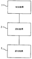
図1を参照すると、本教示は、一般に、制動機構1、連結機構2および適用機構3を含む。制動機構1は、ディスクブレーキキャリパー(これについては以下で詳細に説明する)、あるいはほかの任意のブレーキアセンブリ(ドラムブレーキ、エアブレーキまたはこれらの組合せ等)などの各種の適切なブレーキアセンブリの一部でありうる。適用機構3はさまざまな適切な機構であり、これには、例えば、駐車ブレーキレバーまたは駐車ブレーキペダルに接続され、適切な方法で車両を通って取り回される駐車ブレーキのケーブルなどがある。適用機構3は、連結機構2を介して制動機構1に連結され、例示的な駐車ブレーキアセンブリを形成しうる。
With reference to FIG. 1, the present teachings generally include a braking mechanism 1, a
本教示によれば、連結機構2は、適用機構3と制動機構1との間に可変の機械的比率(mechanical ratio)を与えることができる。更に、連結機構2は、連結機構2が、(制動機構1に係合するため)適用機構3によって複数の向きで係合されるように、適用機構3が制動機構1に連結可能としている。制動機構1、連結機構2、適用機構3および/またはこれらの組合せの一部は、相互に一体化されていても、別の部品であってもよい。
According to the present teaching, the
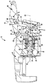
図2乃至5を参照すると、本教示は、キャリパ本体14に連結されうる駐車適用機構12を有するブレーキアセンブリ10を含む。キャリパ本体14は、ハウジング16を有し、その中には1つ以上のピストン18が配置されうる。ピストン18がキャリパ本体14から延びると、ピストン18は、例えば、キャリパ本体14の制動機構1内の液圧流体圧力の増加により、ブレーキパッド20(図3の鎖線に1つのブレーキパッドが示されている)を、ロータ22(図2の鎖線で示される)に対してクランプさせうる。
With reference to FIGS. 2-5, the present teachings include a
図5を参照すると、キャリパ本体14は、流体室24を画定しうる。ピストン18は、フェイス26とスカート28を有しうる。スカート28の一部とアジャスタ機構30は流体室24内にあるが、ピストン18のフェイス26はその外に存在しうる。アジャスタ機構30の各種部品は、本開示の範囲外であるが、共通の譲受人に譲渡された2003年11月25日発行のバルボサ(Barbosa)らの米国特許第6,651,784号に更に詳しく開示されている。この特許は、本明細書に完全に記載したものとして、本明細書にその全体を援用する。
With reference to FIG. 5, the
簡潔に説明すると、アジャスタ機構30は、伸長するか伸縮自在に延びることによって、ブレーキパッド20(図3)および/またはロータ22(図2)の摩耗に対応する。このため、駐車適用機構12は、アジャスタ機構30を付勢してピストン18を延ばすことができ、これにより、ブレーキパッド20をロータ22に対して係合させる。このように、ブレーキパッド20(図3)および/またはロータ22(図2)の摩耗を補償するために、連結機構2および/または適用機構3の部品を調整する必要はないが、これは、アジャスタ機構30が延びて補償するためである。
Briefly described, adjuster mechanism 30 responds to wear of brake pad 20 (FIG. 3) and / or rotor 22 (FIG. 2) by extending or retracting. For this reason, the
アジャスタ機構30は、なかでも、第1端部34と第2端部36を有するロッド部材32を有する。更に、アジャスタ機構30は、フランジ40を有するスリーブナット38を有する。ロッド部材32の第2端部36は、スリーブナット38によって受容されている。駐車適用機構12の連結機構2は、スリーブナットのフランジ40に係合している第1部材42を有する。また、駐車適用機構12は、回転部材46を介して第1部材42に係合する第2部材44も有する。
Among other things, the adjuster mechanism 30 includes a
レバー48は、キャリパ本体14に、および第2部材44に連結しうる。第2部材44が第2軸52上を移動すると、第1部材42は、第2部材44によって付勢され、ほぼピストン軸線50上を移動する。ピストン軸線50は、第2部材44が移動する第2軸52とは通常同一直線上にない。
The
一例では、第1部材42、つまり柱部材42は、スリーブナット38のフランジ40に係合しうる第1端部54を有しうる。柱部材42の第1端部54は、適切なガスケット56を有しうる。柱部材42は、ポケット60を有しうる第2端部58も有しうる。ポケット60は、回転部材46を保持しうる。ガスケット56は、柱部材42の周囲で流体室24を封止し、柱部材42の第1端部54が、流体室のハウジング57に対して移動可能としうる。スリーブナット38と、柱部材42の第1端部54の比較的ごく一部が流体室22内に存在しうるが、柱部材42の残りの部分は流体室22の外にあることを理解すべきである。柱部材42の一部は、キャリパ本体14の流体室のハウジング57の一部によって保持され、このため、柱部材42の移動を、ほぼピストン軸線50上を移動するように制限する。
In one example, the
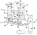
第2部材44、つまりくさび部材44は、第1端部62と第2端部64を有しうる。第1端部62は、ローラ面66を有しうる。第2端部64は、開口68を画定しうる。回転部材46は、柱部材42の第2端部58に形成されたポケット60とローラ面66との間に格納されうる。その際、回転部材46は、ポケット60に保持された状態で、ローラ面66に沿って転がる。図4に示すように、回転部材46は、略円筒形状に構成されうる。別例では、回転部材は、1つ以上のボールベアリング、ローラベアリング、低摩擦スライダ、これらの組合せなどであってもよい。
The
図3および図4を参照すると、レバー48は、第1端部72、第2端部74、およびレバー48を貫通して形成された溝76を有しうる。溝76は、第1端部72と第2端部74の間に設けられうる。ピン78が、レバー48の第1端部72をハウジング16に連結しており、ハウジング16に対する旋回移動を可能にしている。第2端部74は、例えば、別途車両の乗員室の駐車ブレーキレバー/ペダル(特に図示なし)に連結されている、駐車ブレーキのケーブルに接続しうる。
With reference to FIGS. 3 and 4, the
ピン80は、溝76内に配置されて、レバー48をくさび部材44に連結しうる。具体的には、ピン80は、第2端部64から延びる二重の対向するフランジ64aに形成された開口68によって受容されうる。この構成では、ピン80が溝76を通って移動できるため、レバー48が移動すると、くさび部材44が第2軸52上を移動しうる。くさび部材44が第2軸52上を移動すると、くさび部材44は、回転部材46を介して、柱部材42をピストン軸線50上に付勢し、このため制動機構1に係合しうる。
A
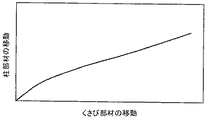
くさび部材44に形成されたローラ面66は、少なくとも次の2つの領域を有しうる。第1領域は凹部82を有しうる。第2領域は斜面84を有しうる。凹部82は、底部86と壁88を有しうる。回転部材46は、最初は凹部82に置かれるが、その後、凹部82の外に出て(すなわち壁88を登って)、ポケット66に保持された状態で斜面84に沿って移動しうる。斜面84の傾斜に対する壁88の傾斜に基づいて、第1領域で回転部材46が移動すると、柱部材42を、所定の移動速度で、くさび部材44から離しうる。回転部材46が第1領域内に存在する間に柱部材42がくさび部材44から離れる移動速度は、回転部材46が第2領域内に存在する場合に、柱部材42がくさび部材44から離れる移動速度よりも高くてもよい。より詳細には、回転部材46は、凹部82の壁88を速く登ることができ、これによって、例えば、ブレーキパッド20とロータ22間のすき間(すなわち、ブレーキパッド20をロータ22に接触させるように移動する初期の移動増分)を、迅速に除去することができる。
The
回転部材46が壁88を速く登ると、連結機構の機械的比率が変化する。回転部材46は、最初は凹部82の壁88の上を登り(または、跳び上がってその外に出て)、次に斜面84を登らなければならないため、くさび部材44の移動距離に対する柱部材42の移動距離の比率が、ローラ面66および上述の領域に対する回転部材46の位置に基づいて変わることが示されうる。回転部材46が凹部82から出て、斜面84を登ると、くさび部材44の所定の距離の移動に対する柱部材42の移動距離が、所定の機械的比率に従って変化することが更に示されうる。例えば、くさび部材44が、第1領域内の回転部材と共に1移動増分だけ移動すると、その結果として柱部材42の第1の移動増分が得られる。同じ増分で、今度はくさび部材44が第2領域内の回転部材46と共に移動すると、その結果として第2の移動増分が得られるが、これは第1の得られた増分よりも少ないことがある。
As the rotating
例えば、図5および図7を参照すると、柱部材42は、初期にはくさび部材44に対して大きな移動速度で移動し、これはローラ面66の第1領域と関連しうる。第2領域内でのくさび部材44の移動は、一般に、柱部材42をくさび部材44と略同じ速度で移動させうる。
For example, referring to FIGS. 5 and 7, the
図5および図8を参照すると、制動機構1によって及ぼされる力は、ブレーキケーブル(図示せず)に及ぼされる所定の力に対して、ほぼ一定である。図5および図9を参照すると、ブレーキケーブルの初期の移動増分(例えば、ブレーキレバーを引くなど)では、ブレーキアセンブリ10によるクランプ力がほとんど発生しない。ケーブルが更に移動すると、ブレーキケーブルの移動の所定の増分に対して、クランプ力が一定量で(すなわち一定の傾斜で)増大する。ケーブルが更に移動すると、ブレーキケーブルの移動の所定の増分に対して、クランプ力が漸増量で(すなわち傾斜が大きくなって)増大する。
Referring to FIGS. 5 and 8, the force exerted by the braking mechanism 1 is substantially constant with respect to a predetermined force exerted on a brake cable (not shown). Referring to FIGS. 5 and 9, there is little clamping force generated by the
一例では、図4を参照すると、くさび部材44、柱部材42および回転部材46はハウジング90内に格納されうる。ハウジング90は、適切な締結具92によってキャリパ本体14に取り付けられうる。くさび部材44とハウジング90の間に、3つのローラベアリング94が配置されうる。この3つのローラベアリング94は、ハウジング90に連結されたローラベアリングプレート96に当接しうる。この構成は、くさび部材44とハウジング90間の摩擦を低減させることが示されうる。更に、くさび部材44は、第2軸52上を移動することができるように保持されうる。また、くさび部材44とハウジング90の間に、スプリング98が保持されうる。スプリング98は、レバー48がくさび部材44を押すと圧縮されて、ピストン18が後退すると、レバー48を元の位置に移動させる力を及ぼしうる。
In one example, referring to FIG. 4, the
一例では、図10、図11および図12を参照すると、レバー48は、キャリパ本体14から延びるフランジ100からヒンジ結合されていてもよい。レバー48は、くさび部材44の端に接触しうる隆起102または丸い突出部を有しうる。レバー48(図11)は、L字状に形成されてもよい。隆起または丸い突出部は、L字状の角104に(あるいはその近くに)形成されうる。
In one example, referring to FIGS. 10, 11, and 12, the
図12を参照すると、レバー48は、鈍角に形成されてもよい。隆起102または丸い突出部は、鈍角の近くの角104に形成されていてもよい。図5、図10乃至図12を参照すると、レバー48は、レバー48および/または適用機構1のほかの適切な部品の向きおよび/または構成に基づいて、さまざまな方向に引くことができる。このため、くさび部材44が第2軸52上を移動するように固定された状態で、レバー48またはその他の適切な部材が、さまざまな角度と向きに向けられ(ハウジング16内で旋回するなど)、このため、レバー48に対して、複数の向きで作動力を与えることが可能となることが理解されよう。さまざまな向きで、作動力および/またはレバー48の位置を決めるかまたは案内することができることにより、車両全体に駐車ブレーキレバー/ペダルおよび/またはブレーキケーブルをさまざまな経路で引き回すことができるようになり、更に、駐車適用機構12の一部を、さまざまな場所および位置に取り付けられられるようになり、実装空間を最小化でき、車両のサスペンションの設計を改善できることが理解されよう。
Referring to FIG. 12, the
図5を参照すると、駐車適用機構12の大部分はブレーキ液室24の外に位置することができ、このことにより、流体室24内に空気がトラップされる傾向が低減される。このように、駐車適用機構12は、キャリパ本体14に締結される別個の部品として作製することができる。さまざまな適切な別個のアセンブリ、モジュールアセンブリ、一体式アセンブリ、およびこれらの組合せが使用されてもよいことが理解されよう。
Referring to FIG. 5, most of the
具体的な例について明細書に記載し、図面に図示したが、特許請求の範囲に記載の本教示の範囲から逸脱することなく、さまざまな変更が可能であり、均等物をその構成要素と置き換えることが可能であることが当業者によって理解されよう。更に、さまざまな例同士で、特徴、要素および/または機能を組み合わせたり一致させたりすることが、本明細書に明示的に考察されうる。これにより、上に特段の記載のない限り、当業者は、本教示から、1つの例の特徴、要素および/または機能を、別の例に組み込むことができることを理解でするであろう。更に、本開示の必須の範囲から逸脱することなく、特定の状況または材料を本教示に適合させるために、さまざまな変更を行うことができる。このため、本教示は、現在本発明のために考えられる最良の形態として明細書に記載され、図示された特定の例に限定されることはなく、本開示の範囲は、前記の説明および添付の特許請求の範囲に入る実施形態を全て含むことが意図される。 While specific examples have been set forth in the specification and illustrated in the drawings, various modifications can be made without departing from the scope of the present teachings as set forth in the claims, and equivalents may be substituted for the components. It will be appreciated by those skilled in the art that this is possible. Furthermore, combining and matching features, elements and / or functions between the various examples may be explicitly discussed herein. Thus, unless otherwise specified above, one of ordinary skill in the art will appreciate from the present teachings that the features, elements and / or functions of one example can be incorporated into another example. In addition, various modifications may be made to adapt a particular situation or material to the teachings without departing from the essential scope of the disclosure. For this reason, the present teachings are described herein as the best mode contemplated for the present invention and are not limited to the specific examples shown, and the scope of the present disclosure is It is intended to include all embodiments that fall within the scope of the following claims.
Claims (10)
前記ピストンに係合するように構成された第1端部、およびポケットを有する第2端部を有する第1部材と、
第1端部および第2端部を有し、前記第2部材の前記第1端部が、斜面部分を有するローラ面を画定している第2部材と、
前記ポケットによって保持され、前記ポケットと前記ローラ面との間に配置された回転部材とを有し、前記第1部材が第1軸上で第1の距離増分を移動し、前記第2部材が第2軸上で第2の距離増分を移動すると、前記回転部材が前記ローラ面に沿って移動し、前記第1軸および前記第2軸は同一直線上になく、前記第1の距離増分および前記第2の距離増分に基づく比率は、前記ローラ面での前記回転部材の位置に基づいて変わる連結機構。 The parking brake assembly includes a braking mechanism, a coupling mechanism, and an application mechanism. The braking mechanism includes a piston that clamps a brake pad with respect to the rotor. The coupling mechanism is a coupling that couples the application mechanism to the braking mechanism. In the mechanism, the coupling mechanism is:
A first member having a first end configured to engage the piston and a second end having a pocket;
A second member having a first end and a second end, wherein the first end of the second member defines a roller surface having a beveled portion;
A rotating member held by the pocket and disposed between the pocket and the roller surface, the first member moving a first distance increment on a first axis, and the second member Moving a second distance increment on the second axis moves the rotating member along the roller surface so that the first axis and the second axis are not collinear and the first distance increment and The ratio based on the second distance increment is a coupling mechanism that changes based on the position of the rotating member on the roller surface.
出力部材に連結された少なくとも1つの入力部材を有し、前記入力部材はほぼ第1軸上を移動し、前記出力部材はほぼ第2軸上を移動し、前記出力部材は、前記回転部材に対して前記摩擦材料を付勢するために前記制動機構に係合する第1端部を有し、前記第1軸および前記第2軸は同一直線上になく、前記入力部材の移動増分および前記出力部材の移動増分に基づく比率が、前記入力部材および前記出力部材の前記移動に伴って変更する連結機構。 The parking brake assembly has a braking mechanism and a coupling mechanism, and the braking mechanism is a coupling mechanism that exerts a clamping force to bias the friction material against the rotating member, and the coupling mechanism includes:
And at least one input member connected to the output member, the input member moves substantially on the first axis, the output member moves substantially on the second axis, and the output member is connected to the rotating member. A first end that engages the brake mechanism to bias the friction material against the first shaft and the second shaft are not collinear, the input member movement increment and the A coupling mechanism in which a ratio based on the movement increment of the output member changes with the movement of the input member and the output member.
流体室に少なくともその一部が配置されているピストンと、
前記ピストンを延ばす前記キャリパ本体に連結され、第1部材、第2部材および回転部材を有する駐車適用機構と、
前記第1部材は、前記ピストンに係合するように適合された第1端部、および第2端部を有し、
前記第2部材は、ローラ面を画定している第1端部、および第2端部を有し、
前記回転部材は、前記第1部材の前記第2端部と前記ローラ面との間に存在し、
前記ローラ面に形成された斜面と、を有し、前記回転部材が前記斜面を移動すると、前記第1部材が、第2の距離を移動する前記第2部材に対して第1の距離を移動され、前記第1の距離および前記第2の距離に基づく比率は、前記ローラ面での位置に基づいて変わり、前記駐車ブレーキアセンブリは前記流体室のほぼ外にあるキャリパ本体。 A caliper body that clamps a brake pad against a rotor, the caliper body,
A piston, at least part of which is disposed in the fluid chamber;
A parking application mechanism coupled to the caliper body extending the piston and having a first member, a second member and a rotating member;
The first member has a first end adapted to engage the piston, and a second end;
The second member has a first end defining a roller surface and a second end;
The rotating member exists between the second end of the first member and the roller surface;
A slope formed on the roller surface, and when the rotating member moves on the slope, the first member moves a first distance relative to the second member moving a second distance. And a ratio based on the first distance and the second distance varies based on a position on the roller surface, and the parking brake assembly is substantially outside the fluid chamber.
Applications Claiming Priority (1)
| Application Number | Priority Date | Filing Date | Title |
|---|---|---|---|
| US11/390,628 US20070227837A1 (en) | 2006-03-28 | 2006-03-28 | Wedge roller ramp parking brake assembly |
Publications (1)
| Publication Number | Publication Date |
|---|---|
| JP2007263369A true JP2007263369A (en) | 2007-10-11 |
Family
ID=38169623
Family Applications (1)
| Application Number | Title | Priority Date | Filing Date |
|---|---|---|---|
| JP2007083203A Pending JP2007263369A (en) | 2006-03-28 | 2007-03-28 | Wedge roller bevel parking brake assembly |
Country Status (4)
| Country | Link |
|---|---|
| US (1) | US20070227837A1 (en) |
| EP (1) | EP1840404A1 (en) |
| JP (1) | JP2007263369A (en) |
| CN (1) | CN101055007A (en) |
Families Citing this family (8)
| Publication number | Priority date | Publication date | Assignee | Title |
|---|---|---|---|---|
| US20080149434A1 (en) * | 2006-11-29 | 2008-06-26 | Akebono Corporation (North America) | Parking brake and actuator mechanism |
| JP4789853B2 (en) * | 2007-05-09 | 2011-10-12 | 日信工業株式会社 | Disc brake device |
| KR20080111872A (en) * | 2007-06-20 | 2008-12-24 | 현대모비스 주식회사 | Electronic controlled wedge brake system with single motor |
| KR100897941B1 (en) * | 2007-09-12 | 2009-05-18 | 현대모비스 주식회사 | Solenoid assisting force generated type Single Motor Electric Wedge Brake System |
| KR100897942B1 (en) * | 2007-09-17 | 2009-05-18 | 현대모비스 주식회사 | Parking force locking type Single Motor Electronic Wedge Brake System |
| US8267227B2 (en) * | 2008-07-22 | 2012-09-18 | Akebono Brake Corporation | Lever assembly featuring blind cable assembly |
| JP6137868B2 (en) * | 2013-02-25 | 2017-05-31 | 住友重機械工業株式会社 | Parking brake device |
| EP3184841B1 (en) * | 2015-12-22 | 2018-08-22 | Haldex Brake Products AB | Disc brake |
Family Cites Families (71)
| Publication number | Priority date | Publication date | Assignee | Title |
|---|---|---|---|---|
| US2820530A (en) * | 1954-02-23 | 1958-01-21 | Automotive Prod Co Ltd | Operating mechanism for disc brakes |
| US2850119A (en) * | 1954-11-03 | 1958-09-02 | Goodyear Tire & Rubber | Mechanical wedge-lock parking brake |
| US3037584A (en) * | 1958-09-02 | 1962-06-05 | Rockwell Standard Co | Wedge actuated brake assembly |
| US3050156A (en) * | 1959-09-10 | 1962-08-21 | Rockwell Standard Co | Right angle, lever-wedge actuated mechanical brake |
| US3194349A (en) * | 1963-03-06 | 1965-07-13 | Lambert & Brake Corp | Wedge operated spot brake |
| US3237724A (en) * | 1964-01-31 | 1966-03-01 | Lambert & Brake Corp | Cam-operated, spot brake structure |
| US3227247A (en) * | 1964-02-10 | 1966-01-04 | Rockwell Standard Co | Brake mechanisms |
| US3425519A (en) * | 1966-06-11 | 1969-02-04 | Teves Kg Alfred | Disk-brake system including plural actuators |
| GB1175556A (en) * | 1966-06-18 | 1969-12-23 | Teves Gmbh Alfred | Improvements in or relating to Motor Vehicle Brakes |
| DE1625755C3 (en) * | 1967-12-02 | 1979-11-15 | Knorr-Bremse Gmbh, 8000 Muenchen | Automatic readjusting device for a floating-caliper partially lined disc brake, in particular for rail vehicles |
| US3662864A (en) * | 1969-11-05 | 1972-05-16 | Kelsey Hayes Co | Disk type brake with split primary shoe |
| US3651896A (en) * | 1970-06-19 | 1972-03-28 | Dayton Steel Foundry Co | Hydraulic disk brake with mechanical actuator |
| GB1456244A (en) * | 1973-01-27 | 1976-11-24 | Girling Ltd | Brake adjusters |
| GB1451327A (en) * | 1973-02-23 | 1976-09-29 | Girling Ltd | Brake actuator mechanisms provided with automatic slack adjusters |
| GB1506852A (en) * | 1974-06-13 | 1978-04-12 | Girling Ltd | Vehicle brake actuators |
| GB1476798A (en) * | 1974-11-15 | 1977-06-16 | Girling Ltd | Actuator assemblies for vehicle brakes |
| US3997033A (en) * | 1975-01-02 | 1976-12-14 | Airheart Products, Inc. | Cam operated disc brake |
| US3966028A (en) * | 1975-03-07 | 1976-06-29 | Rockwell International Corporation | Automatic brake adjusting mechanism |
| GB1509398A (en) * | 1975-10-03 | 1978-05-04 | Girling Ltd | Automatic slack adjusters for vehicle brakes |
| US3991859A (en) * | 1976-02-27 | 1976-11-16 | General Motors Corporation | Adjusting mechanism for a disc brake caliper assembly |
| GB1585092A (en) * | 1976-05-05 | 1981-02-25 | Girling Ltd | Disc brakes for vehicles |
| US4064973A (en) * | 1976-11-18 | 1977-12-27 | The Bendix Corporation | Actuating and adjusting mechanism for disc brakes |
| EP0008876B1 (en) * | 1978-09-02 | 1982-06-02 | Automotive Products Public Limited Company | Brake applying device |
| US4235312A (en) * | 1978-10-30 | 1980-11-25 | Eaton Corporation | Brake actuator assembly |
| US4222310A (en) * | 1978-12-04 | 1980-09-16 | Eaton Corporation | Brake actuator fastener assembly |
| US4194596A (en) * | 1978-12-29 | 1980-03-25 | Eaton Corporation | Disc brake housing assembly |
| DE2946851A1 (en) * | 1979-11-20 | 1981-06-11 | Alfred Teves Gmbh, 6000 Frankfurt | MECHANICAL BRAKE-ACTUATING DEVICE FOR PARTIAL PAD DISC BRAKES |
| US4351419A (en) * | 1980-05-07 | 1982-09-28 | Eaton Corporation | Automatic slack adjuster |
| ZA821438B (en) * | 1981-03-14 | 1983-02-23 | Dunlop Ltd | Brakes |
| US4454933A (en) * | 1981-04-27 | 1984-06-19 | Kelsey Hayes Company | Disc brake |
| US4394890A (en) * | 1981-08-03 | 1983-07-26 | Eaton Corporation | Automatic slack adjuster |
| US4519482A (en) * | 1982-02-05 | 1985-05-28 | Allied Corporation | Wedge actuated drum brake assembly |
| US4535875A (en) * | 1982-03-09 | 1985-08-20 | Lucas Industries, Public Limited Company | Actuator for an internal shoe drum brake |
| EP0110637B1 (en) * | 1982-11-25 | 1987-07-22 | LUCAS INDUSTRIES public limited company | Improvements in disc brakes for vehicles |
| US4544045A (en) * | 1983-04-01 | 1985-10-01 | Allied Corporation | Mechanical actuator for a disc brake |
| US4549422A (en) * | 1983-04-29 | 1985-10-29 | Harrow Donald A | Cup and roll machine |
| FR2554194B1 (en) * | 1983-10-28 | 1986-01-17 | Dba | AUTOMATICALLY ADJUSTABLE BRAKE MOTOR |
| FR2560319B1 (en) * | 1984-02-29 | 1986-07-04 | Dba | ACTUATION MECHANISM WITH HYDRAULIC AND MECHANICAL CONTROLS FOR DISC BRAKE |
| JPS60205034A (en) * | 1984-03-28 | 1985-10-16 | Aisin Seiki Co Ltd | Disc brake with parking brake mechanism |
| SE455635B (en) * | 1985-05-10 | 1988-07-25 | Garphyttan Haldex Ab | CONTROL DEVICE FOR A PRESSURE BAR FOR A BRAKE CYLINDER AT A VEIL BRAKE ARRANGEMENT |
| US4666022A (en) * | 1985-07-01 | 1987-05-19 | Lucas Industries Public Limited Company | Wedge-type brake actuator |
| US4633978A (en) * | 1985-07-22 | 1987-01-06 | Hoffco, Inc. | Brake caliper includes mechanical actuator with camming device and manual wear compensator |
| DE3540671A1 (en) * | 1985-11-16 | 1987-05-21 | Rockwell Golde Gmbh | SPREAD WEDGE BRAKE CONTROL DEVICE |
| FR2590219B1 (en) * | 1985-11-20 | 1991-02-01 | Bendix France | ELECTRIC BRAKING DEVICE FOR VEHICLE |
| FR2600388B1 (en) * | 1986-06-18 | 1988-09-09 | Bendix France | BRAKE MOTOR COMPRISING A RESETABLE AUTOMATIC ADJUSTMENT DEVICE |
| GB8621944D0 (en) * | 1986-09-11 | 1986-10-15 | Lucas Ind Plc | Self-energising disc brakes |
| GB8623225D0 (en) * | 1986-09-26 | 1986-10-29 | Lucas Ind Plc | Wedge & roller actuator |
| GB8624800D0 (en) * | 1986-10-16 | 1986-11-19 | Lucas Ind Plc | Disc brakes |
| DE3841593A1 (en) * | 1988-04-28 | 1990-06-13 | Perrot Bremse Gmbh Deutsche | MECHANICALLY ACTUATED SLIDING CALIPER DISC BRAKE |
| US5038895A (en) * | 1988-10-24 | 1991-08-13 | Kelsey-Hayes Company | Automatic adjusting mechanism for a disc brake assembly having a mechanically actuated parking brake |
| DE8900277U1 (en) * | 1989-01-11 | 1990-05-10 | Lucas Industries P.L.C., Birmingham, West Midlands, Gb | |
| GB8904852D0 (en) * | 1989-03-02 | 1989-04-12 | Lucas Ind Plc | Disc brakes for vehicles |
| US5249648A (en) * | 1990-01-31 | 1993-10-05 | Bendix Europe Services Techniques | Wedge type disc brake |
| GB9114649D0 (en) * | 1991-07-06 | 1991-08-21 | Lucas Ind Plc | Liquid-immersed disc brake |
| FR2697307B1 (en) * | 1992-10-22 | 1994-12-30 | Alliedsignal Europ Services | Space-saving brake motor. |
| FR2701526B1 (en) * | 1993-02-16 | 1995-04-28 | Alliedsignal Europ Services | Device with ball trays and centering cage. |
| DE9407623U1 (en) * | 1994-05-06 | 1995-09-07 | Lucas Ind Plc | Actuating device for a vehicle brake, in particular disc brake |
| FR2741412B1 (en) * | 1995-11-17 | 1998-02-13 | Alliedsignal Europ Services | INCREASED TOLERANCE BRAKE MOTOR |
| SE511851C2 (en) * | 1997-04-24 | 1999-12-06 | Sab Wabco Ab | brake actuator |
| CN1211691A (en) * | 1997-09-12 | 1999-03-24 | 陈坤 | Mechanical disc type brake and clutch |
| GB9721723D0 (en) * | 1997-10-15 | 1997-12-10 | Rover Group | Vehicle brake systems |
| DE19819564C2 (en) * | 1998-04-30 | 2000-06-08 | Deutsch Zentr Luft & Raumfahrt | Self-energizing electromechanical brake |
| FR2778712A1 (en) * | 1998-05-14 | 1999-11-19 | Bosch Syst Freinage | Wear compensator for motor vehicle disc brake |
| GB9823200D0 (en) * | 1998-10-24 | 1998-12-16 | Lucas Ind Plc | Parking-braking in vehicles |
| DE19938592C2 (en) * | 1999-08-18 | 2003-02-27 | Deutsch Zentr Luft & Raumfahrt | Aircraft or spacecraft-borne radar system with synthetic antenna aperture |
| WO2001018423A1 (en) * | 1999-09-07 | 2001-03-15 | Akebono Corporation North America | Automatically-adjusting, hand-brake actuator and housing of light weight material |
| JP2001107999A (en) * | 1999-10-07 | 2001-04-17 | Nisshinbo Ind Inc | Drum brake device |
| DE10004058B4 (en) * | 2000-02-01 | 2004-12-09 | Conti Temic Microelectronic Gmbh | braking device |
| JP4000949B2 (en) * | 2002-08-08 | 2007-10-31 | 株式会社アドヴィックス | Wedge-operated brake device |
| US6920964B1 (en) * | 2003-12-12 | 2005-07-26 | Robert Bosch Corporation | Automated hydraulic brake |
| US7188710B2 (en) * | 2004-02-09 | 2007-03-13 | Delphi Technologies, Inc. | Hydraulic brake actuator comprising electrically actuable lock for park brake |
-
2006
- 2006-03-28 US US11/390,628 patent/US20070227837A1/en not_active Abandoned
-
2007
- 2007-03-27 EP EP07006257A patent/EP1840404A1/en not_active Withdrawn
- 2007-03-28 CN CNA200710091894XA patent/CN101055007A/en active Pending
- 2007-03-28 JP JP2007083203A patent/JP2007263369A/en active Pending
Also Published As
| Publication number | Publication date |
|---|---|
| EP1840404A1 (en) | 2007-10-03 |
| CN101055007A (en) | 2007-10-17 |
| US20070227837A1 (en) | 2007-10-04 |
Similar Documents
| Publication | Publication Date | Title |
|---|---|---|
| JP2007263369A (en) | Wedge roller bevel parking brake assembly | |
| US8220596B2 (en) | Disc brake for a commercial vehicle | |
| US20110005871A1 (en) | Pneumatically Actuated Disc Brake with Actuation Tappet | |
| KR20150074113A (en) | Disk brake with a parking brake, mechanical thrust assembly, and method of assembling | |
| CN1326059A (en) | Braking mechanism and caliper for disk brake | |
| US10161466B2 (en) | Brake device | |
| US11965567B2 (en) | Disc brake | |
| US8205724B2 (en) | Disc brake device | |
| JP4658527B2 (en) | Disc brake with self-boosting action | |
| JP2008296756A (en) | Disc brake device for railway vehicle | |
| US20070068747A1 (en) | Self-energizing sliding caliper | |
| JP3706590B2 (en) | Automatic adjustment of disc brake pads | |
| US6112864A (en) | Disc brake | |
| US20090057075A1 (en) | Ball-in-ramp brake caliper type parking brake for vehicle | |
| US5558185A (en) | Input lever for actuating a push rod for a brake motor | |
| JPH0135218B2 (en) | ||
| JP6118697B2 (en) | Disc brake | |
| JPH0130662Y2 (en) | ||
| JP2007232041A (en) | Vehicular disk brake device | |
| JP5232523B2 (en) | Wheel cylinder integrated automatic adjustment device | |
| JPH0134764Y2 (en) | ||
| JP5260427B2 (en) | Floating disc brake device | |
| KR20090043187A (en) | Disk brake for vehicle | |
| JP2008095816A (en) | Disc brake device | |
| CN114829799A (en) | Disc brake |