JP2007263003A - Exhaust pipe structure in upstream side of catalytic converter - Google Patents
Exhaust pipe structure in upstream side of catalytic converter Download PDFInfo
- Publication number
- JP2007263003A JP2007263003A JP2006089933A JP2006089933A JP2007263003A JP 2007263003 A JP2007263003 A JP 2007263003A JP 2006089933 A JP2006089933 A JP 2006089933A JP 2006089933 A JP2006089933 A JP 2006089933A JP 2007263003 A JP2007263003 A JP 2007263003A
- Authority
- JP
- Japan
- Prior art keywords
- exhaust pipe
- catalytic converter
- upstream side
- pipe structure
- upstream
- Prior art date
- Legal status (The legal status is an assumption and is not a legal conclusion. Google has not performed a legal analysis and makes no representation as to the accuracy of the status listed.)
- Pending
Links
Images


Landscapes
- Exhaust Gas After Treatment (AREA)
- Exhaust Gas Treatment By Means Of Catalyst (AREA)
- Exhaust Silencers (AREA)
Abstract
Description
本発明は、触媒コンバータの上流側排気管構造に関する。 The present invention relates to an upstream exhaust pipe structure of a catalytic converter.
排気ガス浄化のために自動車等の排気系に介装される触媒コンバータは、通常エンジンより下方位置に備えられる関係で、図19に示すように、触媒コンバータ101の上流側排気管102に略垂直方向から略水平方向に曲がる曲がり部102aが存在しているため、この曲がり部102aを通過する際に、排気ガスの主流が下方に集中する偏流となり、その状態でディフューザ103を通過し触媒担体に片当たりして触媒担体断面を部分的に通過するようになる結果、触媒担体の有効断面積を十分に活用することなく浄化率が低下するという問題があった。
A catalytic converter interposed in an exhaust system of an automobile or the like for exhaust gas purification is generally provided at a lower position than the engine, and is substantially perpendicular to the
また、触媒担体が部分的に加熱されることで、温度分布差による触媒担体の割れを生じさえる虞があるという問題もあった。 There is also a problem that the catalyst carrier may be partially heated, which may cause cracking of the catalyst carrier due to a temperature distribution difference.
そこで、上述のような問題点を解消するものとして、複数の平行流路をもち、該流路が、高めの密度を持つ第1セル群及び低めの密度を持つ第2セル群を有する触媒担体を採用するようにした技術が開示されている(例えば、特許文献1参照。)。
しかしながら、従来例の触媒コンバータ構造では、触媒担体の構造が複雑で、大幅なコストアップに繋がると共に、触媒担体が部分的に加熱されることで、温度分布差による触媒担体の割れを防止することができないという問題点がある。 However, in the conventional catalytic converter structure, the structure of the catalyst carrier is complicated, which leads to a significant cost increase, and the catalyst carrier is partially heated to prevent cracking of the catalyst carrier due to a temperature distribution difference. There is a problem that can not be.
本発明の解決しようとする課題は、触媒担体は従来のままで、コストアップを抑制しつつ、触媒担体の有効断面積を十分に活用して浄化率の低下を防止すると共に、温度分布差による触媒担体の割れを防止することができる触媒コンバータの上流側排気管構造を提供することにある。 The problem to be solved by the present invention is that the catalyst carrier remains the same as the conventional one, while suppressing an increase in cost, the effective cross-sectional area of the catalyst carrier is fully utilized to prevent a reduction in purification rate, and due to a temperature distribution difference. An object of the present invention is to provide an upstream exhaust pipe structure of a catalytic converter that can prevent cracking of a catalyst carrier.
上記課題を解決するため請求項1記載の触媒コンバータの上流側排気管構造は、触媒コンバータの上流側排気管に曲がり部を有する触媒コンバータの上流側排気管構造であって、前記上流側排気管における前記曲がり部の下流側の前記触媒コンバータの流入口付近に整流部が形成されていることを特徴とする手段とした。
In order to solve the above problems, the upstream exhaust pipe structure of the catalytic converter according to
本発明の触媒コンバータの上流側排気管構造では、上述のように、上流側排気管における前記曲がり部の下流側の前記触媒コンバータの流入口付近に整流部が形成されている構成としたことで、曲がり部を通過して偏流となった排気ガスが整流部で整流された状態で触媒コンバータに流入されるようになるため、触媒担体の有効断面積を十分に活用して浄化率の低下を防止すると共に、温度分布差による触媒担体の割れを防止することができるようになるという効果が得られる。 In the upstream side exhaust pipe structure of the catalytic converter of the present invention, as described above, the rectification part is formed in the vicinity of the inlet of the catalytic converter on the downstream side of the bent part in the upstream side exhaust pipe. The exhaust gas that has drifted through the bent part flows into the catalytic converter after being rectified by the rectifying part, so that the effective sectional area of the catalyst carrier is fully utilized to reduce the purification rate. In addition to preventing, cracking of the catalyst carrier due to temperature distribution difference can be prevented.
また、触媒担体として同一密度のセル群で構成される従来品が使用可能であり、かつ、整流部は上流側排気管に形成されるものであるため、触媒コンバータ側に形成する場合に比べ、形成が容易であり、従って、コストアップを大幅に抑制することができるようになる。 In addition, since a conventional product composed of a group of cells having the same density can be used as the catalyst carrier, and the rectification unit is formed on the upstream side exhaust pipe, compared to the case where it is formed on the catalytic converter side, It is easy to form, and therefore the cost increase can be greatly suppressed.
以下にこの発明の実施例を図面に基づいて説明する。 Embodiments of the present invention will be described below with reference to the drawings.
まず、この実施例1の触媒コンバータの上流側排気管構造を図面に基づいて説明する。 First, the upstream side exhaust pipe structure of the catalytic converter of the first embodiment will be described with reference to the drawings.
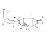
図1はこの実施例1の触媒コンバータの上流側排気管構造を示す一部切欠側面図、図2は図1のA−A線における拡大縦断面図である。 FIG. 1 is a partially cutaway side view showing an upstream side exhaust pipe structure of the catalytic converter of the first embodiment, and FIG. 2 is an enlarged longitudinal sectional view taken along line AA of FIG.
この触媒コンバータの上流側排気管構造は、触媒コンバータ1と、上流側排気管2と、出力側排気管3とを備えている。
The upstream exhaust pipe structure of the catalytic converter includes a
さらに詳述すると、上記触媒コンバータ1は、触媒担体11と、外筒12と、ディフューザ13、14とで構成されている。
More specifically, the
上記触媒担体11は、セラミック又は金属板で多数の孔を有するハニカム状に形成され、その表面にPt、rh、Pd等の金属触媒が担持されている。
The
上記外筒12は、その内部に触媒担体11が圧入されることにより、触媒コンバータの外形を形成するもので、その両端開口縁部にディフューザ13、14の大径開口部側がそれぞれ溶接により接続されている。
The
即ち、このディフューザ13、14は、外筒12を触媒担体11を該触媒担体11より小径の上流側排気管2と出力側排気管3に接続するための介装部材であり、その小径側開口部側に上流側排気管2と出力側排気管3がそれぞれ溶接により接続されている。
That is, the
上記上流側排気管2は、触媒コンバータ1が、エンジンより下方位置に備えられる関係で、その途中に略垂直方向から略水平方向に曲がる曲がり部21が存在している。
The
そして、上流側排気管2における曲がり部21の下流側に整流部4が形成されている。即ち、この整流部4は、上流側排気管2の上面側の一部を所定長さに亘って下方へ押し潰すことにより、略半円状に変形された流路断面部分で構成されている。
And the rectification | straightening
次に、この実施例1の作用・効果を説明する。 Next, operations and effects of the first embodiment will be described.
この実施例1の触媒コンバータの上流側排気管構造では、上述のように、上流側排気管2における曲がり部21の下流側に整流部4が形成されている構成としたことで、曲がり部21を通過して偏流となった排気ガスが整流部4を通過する際に流れの変化を得て整流された状態で触媒コンバータ1に流入されるようになるため、触媒担体11の有効断面積を十分に活用して浄化率の低下を防止すると共に、温度分布差による触媒担体11の割れを防止することができるようになるという効果が得られる。
In the upstream side exhaust pipe structure of the catalytic converter of the first embodiment, as described above, the rectifying
また、触媒担体11として同一密度のセル群で構成される従来品が使用可能であり、かつ、整流部4は上流側排気管2に形成されるものであるため、触媒コンバータ1側に形成する場合に比べ、形成が容易であり、従って、コストアップを大幅に抑制することができるようになる。
Moreover, since the conventional product comprised by the cell group of the same density can be used as the catalyst support |
次に、他の実施例について説明する。この他の実施例の説明にあたっては、前記実施例1と同様の構成部分については図示を省略し、もしくは同一の符号を付けてその説明を省略し、相違点についてのみ説明する。 Next, another embodiment will be described. In the description of the other embodiments, the same components as those of the first embodiment are not shown, or the same reference numerals are given and the description thereof is omitted, and only the differences are described.
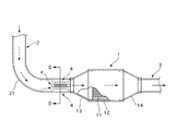
この実施例2は、実施例1における触媒コンバータの上流側排気管構造の変形例を示すものであり、図3(一部切欠側面図)、図4(図3のB−B線における拡大縦断面図)に示すように、整流部4が、上流側排気管2の上面側の一部を側面視で略V字状に下方へ押し潰すことにより、略半円状に変形された流路断面部分で構成されている点で、上記実施例とは相違したものである。
従って、この実施例2においても、曲がり部21を通過して偏流となった排気ガスが整流部4を通過する際に流れの変化を得て整流された状態で触媒コンバータ1に流入されるようになるため上記実施例1と同様の効果が得られる。
The second embodiment shows a modification of the upstream side exhaust pipe structure of the catalytic converter in the first embodiment. FIG. 3 (partially cutaway side view) and FIG. 4 (enlarged longitudinal section along line BB in FIG. 3). As shown in FIG. 2, the flow path deformed into a substantially semicircular shape when the rectifying
Therefore, also in the second embodiment, the exhaust gas that has drifted through the
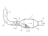
この実施例3は、実施例1における触媒コンバータの上流側排気管構造の変形例を示すものであり、図5(一部切欠側面図)、図6(図5のC−C線における拡大縦断面図)に示すように、整流部4が、上流側排気管2の上下両面側の一部を所定長さに亘って下方へ押し潰すことにより、略横長楕円状に変形された流路断面部分で構成されている点で、上記実施例とは相違したものである。
従って、この実施例3においても、曲がり部21を通過して偏流となった排気ガスが整流部4を通過する際に流れの変化を得て整流された状態で触媒コンバータ1に流入されるようになるため、上記実施例1と同様の効果が得られる。
The third embodiment shows a modification of the upstream side exhaust pipe structure of the catalytic converter in the first embodiment. FIG. 5 (partially cutaway side view) and FIG. 6 (enlarged longitudinal section along the line CC in FIG. 5). As shown in FIG. 2, the
Accordingly, also in the third embodiment, the exhaust gas that has flowed through the
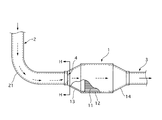
この実施例4は、実施例1における触媒コンバータの上流側排気管構造の変形例を示すものであり、図7(一部切欠側面図)、図8(図7のD−D線における拡大縦断面図)に示すように、整流部4が、上流側排気管2の周方向4カ所を所定長さに亘って下方へ押し潰すことにより、花びら状に変形された流路断面部分で構成されている点で、上記実施例とは相違したものである。
The fourth embodiment shows a modification of the upstream side exhaust pipe structure of the catalytic converter in the first embodiment. FIG. 7 (partially cutaway side view) and FIG. 8 (enlarged longitudinal section along the line DD in FIG. 7). As shown in the plan view), the rectifying
また、整流部4が、上記排気管2の他にしゅう方向複数箇所、斜め下方に潰すことも実施例1とは相違したものである。
Further, the rectifying
従って、この実施例4においても、曲がり部21を通過して偏流となった排気ガスが整流部4を通過する際に流れの変化を得て整流された状態で触媒コンバータ1に流入されるようになるため、上記実施例1と同様の効果が得られる。
Therefore, also in the fourth embodiment, the exhaust gas that has flowed through the
この実施例5は、実施例1における触媒コンバータの上流側排気管構造の変形例を示すものであり、図9(一部切欠側面図)、図10(図9のE−E線における拡大縦断面図)に示すように、整流部4が、上流側排気管2の軸線方向所定間隔のもとに、該上流側排気管2を周方向リング状に下方へ押し潰すことにより、蛇腹状に変形された流路断面部分で構成されている点で、上記実施例とは相違したものである。
従って、この実施例5においても、曲がり部21を通過して偏流となった排気ガスが整流部4を通過する際に流れの変化を得て整流された状態で触媒コンバータ1に流入されるようになるため、上記実施例1と同様の効果が得られる。
The fifth embodiment shows a modification of the upstream side exhaust pipe structure of the catalytic converter in the first embodiment. FIG. 9 (partially cutaway side view) and FIG. 10 (enlarged longitudinal section along line EE in FIG. 9). As shown in FIG. 2, the rectifying
Therefore, also in the fifth embodiment, the exhaust gas that has flowed through the
この実施例6は、実施例1における触媒コンバータの上流側排気管構造の変形例を示すものであり、図11(一部切欠側面図)、図12(図11のF−F線における拡大縦断面図)に示すように、整流部4が、上流側排気管2を軸線方向螺旋状に下方へ押し潰すことにより、内向きに突出する螺旋状の突条が形成された流路断面部分で構成されている点で、上記実施例とは相違したものである。
従って、この実施例6においても、曲がり部21を通過して偏流となった排気ガスが整流部4を通過する際に流れの変化を得て整流された状態で触媒コンバータ1に流入されるようになるため、上記実施例1と同様の効果が得られる。
The sixth embodiment shows a modification of the upstream side exhaust pipe structure of the catalytic converter in the first embodiment. FIG. 11 (partially cutaway side view) and FIG. 12 (enlarged longitudinal section taken along line FF in FIG. 11). As shown in the plan view), the
Therefore, also in the sixth embodiment, the exhaust gas that has flowed through the
この実施例7は、実施例1における触媒コンバータの上流側排気管構造の変形例を示すものであり、図13(一部切欠側面図)、図14(図13のG−G線における拡大縦断面図)に示すように、整流部4が、上流側排気管2の管端開口部の略上半分内側へ折り曲げることにより、略横長楕円状に形成された流路断面部分で構成されている点で、上記実施例とは相違したものである。
従って、この実施例7においても、曲がり部21を通過して偏流となった排気ガスが整流部4を通過する際に流れの変化を得て整流された状態で触媒コンバータ1に流入されるようになるため、上記実施例1と同様の効果が得られる。
The seventh embodiment shows a modification of the upstream side exhaust pipe structure of the catalytic converter in the first embodiment. FIG. 13 (partially cutaway side view) and FIG. 14 (enlarged longitudinal section along line GG in FIG. 13). As shown in FIG. 2, the rectifying
Therefore, also in the seventh embodiment, the exhaust gas that has flowed through the
この実施例8は、実施例1における触媒コンバータの上流側排気管構造の変形例を示すものであり、図15(一部切欠側面図)、図16(図15のH−H線における拡大縦断面図)に示すように、整流部4が、上流側排気管2の管端開口縁部を内側へ絞り込んで縮径された流路断面部分で構成されている点で、上記実施例とは相違したものである。
従って、この実施例8においても、曲がり部21を通過して偏流となった排気ガスが整流部4を通過する際に流れの変化を得て整流された状態で触媒コンバータ1に流入されるようになるため、上記実施例1と同様の効果が得られる。
The eighth embodiment shows a modification of the upstream side exhaust pipe structure of the catalytic converter in the first embodiment. FIG. 15 (partially cutaway side view) and FIG. 16 (enlarged longitudinal section along line HH in FIG. 15). As shown in the plan view), the rectifying
Accordingly, also in the eighth embodiment, the exhaust gas that has flowed through the
この実施例9は、実施例1における触媒コンバータの上流側排気管構造の変形例を示すものであり、図17(一部切欠側面図)、図18(図17のJ−J線における拡大縦断面図)に示すように、整流部4が、上流側排気管2の一部を略球状に膨らませることにより、拡径された流路断面部分で構成されている点で、上記実施例とは相違したものである。
従って、この実施例9においても、曲がり部21を通過して偏流となった排気ガスが整流部4を通過する際に流れの変化を得て整流された状態で触媒コンバータ1に流入されるようになるため、上記実施例1と同様の効果が得られる。
The ninth embodiment shows a modification of the upstream side exhaust pipe structure of the catalytic converter in the first embodiment. FIG. 17 (partially cutaway side view) and FIG. 18 (enlarged longitudinal section along line JJ in FIG. 17). As shown in FIG. 2, the rectifying
Therefore, also in the ninth embodiment, the exhaust gas that has flowed through the
以上本実施例を説明してきたが、本発明は上述の実施例に限られるものではなく、本発明の要旨を逸脱しない範囲の設計変更等があっても、本発明に含まれる。 Although the present embodiment has been described above, the present invention is not limited to the above-described embodiment, and design changes and the like within a scope not departing from the gist of the present invention are included in the present invention.
図1はこの実施例1の触媒コンバータの上流側排気管構造を示す一部切欠側面図、図2は図1のA−A線における拡大縦断面図である。
1 触媒コンバータ
11 触媒担体
12 外筒
13 ディフューザ
14 ディフューザ
2 上流側排気管
21 曲がり部
3 出力側排気管
4 整流部
DESCRIPTION OF
Claims (1)
前記上流側排気管における前記曲がり部の下流側の前記触媒コンバータの流入口付近に整流部が形成されていることを特徴とする触媒コンバータの上流側排気管構造。 The upstream exhaust pipe structure of the catalytic converter having a bent portion in the upstream exhaust pipe of the catalytic converter,
An upstream exhaust pipe structure for a catalytic converter, characterized in that a rectifying section is formed in the vicinity of the inlet of the catalytic converter on the downstream side of the bent section in the upstream exhaust pipe.
Priority Applications (1)
| Application Number | Priority Date | Filing Date | Title |
|---|---|---|---|
| JP2006089933A JP2007263003A (en) | 2006-03-29 | 2006-03-29 | Exhaust pipe structure in upstream side of catalytic converter |
Applications Claiming Priority (1)
| Application Number | Priority Date | Filing Date | Title |
|---|---|---|---|
| JP2006089933A JP2007263003A (en) | 2006-03-29 | 2006-03-29 | Exhaust pipe structure in upstream side of catalytic converter |
Publications (1)
| Publication Number | Publication Date |
|---|---|
| JP2007263003A true JP2007263003A (en) | 2007-10-11 |
Family
ID=38636233
Family Applications (1)
| Application Number | Title | Priority Date | Filing Date |
|---|---|---|---|
| JP2006089933A Pending JP2007263003A (en) | 2006-03-29 | 2006-03-29 | Exhaust pipe structure in upstream side of catalytic converter |
Country Status (1)
| Country | Link |
|---|---|
| JP (1) | JP2007263003A (en) |
Cited By (3)
| Publication number | Priority date | Publication date | Assignee | Title |
|---|---|---|---|---|
| WO2014115461A1 (en) * | 2013-01-25 | 2014-07-31 | フタバ産業株式会社 | Exhaust gas purification device |
| WO2014129014A1 (en) * | 2013-02-20 | 2014-08-28 | 本田技研工業株式会社 | Exhaust purification device |
| WO2017208406A1 (en) * | 2016-06-01 | 2017-12-07 | フタバ産業株式会社 | Exhaust pipe |
-
2006
- 2006-03-29 JP JP2006089933A patent/JP2007263003A/en active Pending
Cited By (8)
| Publication number | Priority date | Publication date | Assignee | Title |
|---|---|---|---|---|
| WO2014115461A1 (en) * | 2013-01-25 | 2014-07-31 | フタバ産業株式会社 | Exhaust gas purification device |
| JP5977375B2 (en) * | 2013-01-25 | 2016-08-24 | フタバ産業株式会社 | Exhaust gas purification device |
| JPWO2014115461A1 (en) * | 2013-01-25 | 2017-01-26 | フタバ産業株式会社 | Exhaust gas purification device |
| WO2014129014A1 (en) * | 2013-02-20 | 2014-08-28 | 本田技研工業株式会社 | Exhaust purification device |
| JP5916940B2 (en) * | 2013-02-20 | 2016-05-11 | 本田技研工業株式会社 | Exhaust purification equipment |
| JPWO2014129014A1 (en) * | 2013-02-20 | 2017-02-02 | 本田技研工業株式会社 | Exhaust purification device |
| WO2017208406A1 (en) * | 2016-06-01 | 2017-12-07 | フタバ産業株式会社 | Exhaust pipe |
| JPWO2017208406A1 (en) * | 2016-06-01 | 2018-07-19 | フタバ産業株式会社 | Exhaust pipe |
Similar Documents
| Publication | Publication Date | Title |
|---|---|---|
| US8327633B2 (en) | Exhaust pipe for vehicle-mounted engine | |
| JP6158506B2 (en) | Exhaust gas purification device | |
| JP2007263003A (en) | Exhaust pipe structure in upstream side of catalytic converter | |
| CN105143629A (en) | Catalytic converter | |
| US11377990B2 (en) | Exhaust pipe | |
| US20160312679A1 (en) | Engine Exhaust System Decomposition Tube | |
| JP2014180606A (en) | Honeycomb structure | |
| US20190178138A1 (en) | Honeycomb Body For Exhaust Gas Aftertreatment | |
| US20160115853A1 (en) | Welding structure of warm-up catalytic converter | |
| CN101124391A (en) | Diverter for catalytic converter | |
| JP4831970B2 (en) | Double pipe tube end connection positioning structure by welding to other members | |
| JP6247541B2 (en) | Multi-pipe once-through boiler | |
| JP2013185498A (en) | Exhaust manifold | |
| JPH11350950A (en) | Exhaust system for internal combustion engine | |
| JP2010144710A (en) | Connection structure for hollow double-pipe | |
| US20150275740A1 (en) | Exhaust Apparatus | |
| TWI586471B (en) | Metallic body of the core plate welding structure | |
| EP3628395B1 (en) | Dinitrifcation apparatus for coal fired boiler | |
| JP2010159719A (en) | Exhaust gas passage structure | |
| JP2018059425A (en) | Double pipe structure and double pipe structure manufacturing method | |
| JP2008240587A (en) | Vehicular muffler | |
| JP6215873B2 (en) | Exhaust gas purification device | |
| JP2019167831A (en) | Exhaust passage structure of internal combustion engine | |
| JP2022114613A (en) | Catalytic converter and method for manufacturing catalytic converter | |
| JP2006009693A (en) | Catalytic converter |