JP2007259301A - Network device and communication system - Google Patents
Network device and communication system Download PDFInfo
- Publication number
- JP2007259301A JP2007259301A JP2006083823A JP2006083823A JP2007259301A JP 2007259301 A JP2007259301 A JP 2007259301A JP 2006083823 A JP2006083823 A JP 2006083823A JP 2006083823 A JP2006083823 A JP 2006083823A JP 2007259301 A JP2007259301 A JP 2007259301A
- Authority
- JP
- Japan
- Prior art keywords
- communication
- name
- communication port
- unit
- controller
- Prior art date
- Legal status (The legal status is an assumption and is not a legal conclusion. Google has not performed a legal analysis and makes no representation as to the accuracy of the status listed.)
- Pending
Links
Images


Landscapes
- Computer And Data Communications (AREA)
- Small-Scale Networks (AREA)
Abstract
Description
本発明は、宅内に設置された複数の通信端末とともに通信システムを構成するネットワーク装置、並びにその通信システムに関するものである。 The present invention relates to a network device that constitutes a communication system together with a plurality of communication terminals installed in a house, and to the communication system.
近年、インターネットの普及に伴ってウイルスやワームなどの不正なプログラムや、DoS(Denial of Services:サービス距離攻撃)と呼ばれる不正なアクセスが急増しており、例えば、インターネットに接続されるパーソナルコンピュータには、ウイルスやワームなどの不正なプログラムを検出する機能(いわゆるウイルスチェック機能)などのセキュリティ機能が必須となっている。また、冷蔵庫やテレビ受像機などの機器にデータ伝送機能を付加して通信ケーブルのような伝送路に各機器を接続し、個々の機器間で伝送路を介したパケット交換を行ったり、あるいは伝送路に接続された外部の通信網(インターネットなど)から各機器を制御するといったことが行われている(例えば、特許文献1参照)。 In recent years, unauthorized programs such as viruses and worms and unauthorized access called DoS (Denial of Services) have been rapidly increasing with the spread of the Internet. For example, personal computers connected to the Internet have Security functions such as a function to detect malicious programs such as viruses and worms (so-called virus check function) are indispensable. In addition, data transmission functions are added to devices such as refrigerators and television receivers, and each device is connected to a transmission line such as a communication cable, and packets are exchanged or transmitted between individual devices via the transmission line. Each device is controlled from an external communication network (such as the Internet) connected to the road (for example, see Patent Document 1).
ところで、コンピュータネットワークのような通信システムにおいては、利用者自らがパケットに対する処理(主にウイルスチェックなどのセキュリティに関する処理)の要否を判断して設定することが一般的に行われているが、上述のような機器を含む通信システムにおいては、セキュリティ機能を有する機器と有しない機器とが混在しており、セキュリティ機能を有しない機器に代わってセキュリティに関する処理を行うネットワーク装置が必要となる。 By the way, in a communication system such as a computer network, it is generally performed by the user himself / herself judging and setting the necessity of processing for packets (mainly security processing such as virus check). In a communication system including the above-described devices, a device having a security function and a device having no security function are mixed, and a network device that performs processing related to security is required in place of a device having no security function.
かかるネットワーク装置は、例えば、通信ケーブルが接続される複数の通信ポートと、通信ポートより通信ケーブルを介してデータ通信を行う通信手段と、通信ポート毎にデータ通信の状況を監視して不正なデータ通信が行われている通信ポートを遮断若しくは制限する通信ポート制御手段と、通信ポート制御手段によって遮断若しくは制限された通信ポートを特定するための特定情報を通信手段よりパーソナルコンピュータなどの通信端末に通知する通知手段とを備えている。すなわち、何れかの通信ポートで不正なデータ通信が行われた場合、ネットワーク装置が当該通信ポートを遮断若しくは制限するとともに当該通信ポートの特定情報を通信端末に通知するから、何れの通信ポートが遮断若しくは制限されたかを前記特定情報によって利用者に知らせることができるのである。
しかしながら、従来のネットワーク装置では通信ポートを特定するための特定情報として単なる番号が使われているため、利用者には通信ポートと当該通信ポートに接続されている通信端末(機器)との対応が判りづらく、利便性が低いという問題があった。 However, since a conventional network device uses a simple number as identification information for identifying a communication port, the user can deal with a communication port and a communication terminal (equipment) connected to the communication port. There was a problem that it was difficult to understand and the convenience was low.
本発明は上記事情に鑑みて為されたものであり、その目的は、通信端末と通信ポートとの対応関係を判りやすくして利便性を向上したネットワーク装置並びに通信システムを提供することにある。 The present invention has been made in view of the above circumstances, and an object of the present invention is to provide a network device and a communication system in which the correspondence relationship between a communication terminal and a communication port is easily understood to improve convenience.
請求項1の発明は、上記目的を達成するために、宅内に設置された複数の通信端末とともに通信システムを構成するネットワーク装置であって、伝送路を介して前記通信端末が接続される複数の通信ポートと、該通信ポートより前記伝送路を介してデータ通信を行う通信手段と、各通信ポートに名称を割り当てる名称割当手段とを備えたことを特徴とする。
In order to achieve the above object, the invention of
請求項2の発明は、請求項1の発明において、操作入力を受け付ける操作入力受付手段を備え、前記名称割当手段は、前記操作入力受付手段で受け付けた操作入力に応じた名称を割り当てることを特徴とする。
The invention of claim 2 is the invention of
請求項3の発明は、請求項1の発明において、前記名称割当手段は、前記通信端末から送信され前記通信手段で受信したデータに応じた名称を割り当てることを特徴とする。 According to a third aspect of the present invention, in the first aspect of the invention, the name assigning means assigns a name corresponding to data transmitted from the communication terminal and received by the communication means.
請求項4の発明は、請求項3の発明において、前記名称割当手段は、前記データを受信した通信ポートに対してのみ当該データに応じた名称を割り当てることを特徴とする。 According to a fourth aspect of the present invention, in the third aspect of the invention, the name assigning means assigns a name corresponding to the data only to the communication port that has received the data.
請求項5の発明は、請求項3又は4の発明において、前記名称割当手段は、前記通信端末の要求に応じて、前記通信ポートに割り当てられている名称並びに当該通信ポートに接続されている前記通信端末の種類を少なくとも含む名称割当情報を前記通信手段に送信させることを特徴とする。
The invention according to
請求項6の発明は、上記目的を達成するために、宅内に設置された複数の通信端末と、請求項3〜5の何れかのネットワーク装置と、宅内に配設され前記ネットワーク装置の通信ポートに前記伝送路たる通信ケーブルを挿抜自在に接続するための1乃至複数の情報コンセントとを備えた通信システムであって、前記情報コンセントは、操作入力を受け付けるとともに当該操作入力に応じたデータを前記ネットワーク装置に送信し、前記名称割当手段は、前記情報コンセントから送信され前記通信手段で受信したデータに応じた名称を割り当てることを特徴とする。
In order to achieve the above object, a sixth aspect of the present invention provides a plurality of communication terminals installed in a home, the network device according to any one of
請求項1の発明によれば、名称割当手段によって任意の名称を通信ポートに割り当てることができるから、通信端末と通信ポートとの対応関係を判りやすくして利便性が向上できる。 According to the first aspect of the present invention, since an arbitrary name can be assigned to the communication port by the name assigning means, the correspondence between the communication terminal and the communication port can be easily understood and the convenience can be improved.
請求項2の発明によれば、ネットワーク装置が備える操作入力受付手段を使って通信ポートの名称を割り当てるため、名称の割当作業が簡単になる。 According to the invention of claim 2, since the name of the communication port is assigned using the operation input receiving means provided in the network device, the name assigning operation is simplified.
請求項3の発明によれば、例えば、キーボードのような操作入力受付手段を具備する通信端末(パーソナルコンピュータ)を使って離れた場所から通信ポートの名称を割り当てることができて名称の割当作業がさらに簡単になる。
According to the invention of
請求項4の発明によれば、名称を割り当てる通信ポートが限定されることにより、誤って意図しない名称が割り当てられるのを防止できる。
According to the invention of
請求項5の発明によれば、通信端末を使って名称を割り当てる際、通信ポートに割り当てられている名称並びに当該通信ポートに接続されている通信端末の種類を少なくとも含む名称割当情報を参照することができて名称の割当作業がさらに簡単になる。
According to the invention of
請求項6の発明によれば、通常、パーソナルコンピュータのような汎用の通信端末は、宅内に配設されている情報コンセントに通信ケーブルを接続することでネットワーク装置の通信ポートに接続されるものであり、かかる情報コンセントを使って離れた場所から通信ポートの名称を割り当てることができて名称の割当作業がさらに簡単になる。 According to the invention of claim 6, a general-purpose communication terminal such as a personal computer is normally connected to a communication port of a network device by connecting a communication cable to an information outlet installed in a house. Yes, it is possible to assign the name of the communication port from a remote location using such an information outlet, and the assignment work of the name is further simplified.
以下、住宅設備の制御並びに監視を行う住宅設備監視制御システムに本発明の技術思想を適用した実施形態について、図面を参照して詳細に説明する。 Hereinafter, an embodiment in which the technical idea of the present invention is applied to a housing equipment monitoring control system that controls and monitors housing equipment will be described in detail with reference to the drawings.
本実施形態の住宅設備監視制御システム(通信システム)は、図2に示すように住宅内に設置されたコントローラC1,C2,C3が住宅設備の制御並びに監視を行う複数(図示例では3つ)のサブシステムSS1,SS2,SS3と、各サブシステムSSnのコントローラCn(n=1,2,3)と伝送路(エンハンスト・カテゴリ5若しくはカテゴリ6のLANケーブル)を介して接続されるネットワーク装置(統合管理装置TM)と、統合管理装置TMにLANケーブルを介して接続される複数(図示例では、2つ)の端末装置(パーソナル・コンピュータPC並びに表示制御装置CV)とを備え、これら複数のコントローラCと統合管理装置TMと端末装置とが汎用の通信プロトコル(TCP/IP、UDP、HTTPなど)を利用した宅内ネットワークを構成している。この宅内ネットワークは、100BASE-TX(IEEE 802.3u)規格に準拠したローカルエリアネットワーク(LAN)であって、通信端末に相当する各サブシステムSSnのコントローラCnや端末装置(パーソナルコンピュータPC並びに表示制御装置CV)が、ネットワーク装置に相当する統合管理装置TMにスター配線で接続されている。さらに統合管理装置TMは、インターネットに接続するための回線の種類(電話回線、CATV回線、光ファイバ回線など)に応じてADSLモデムやケーブルモデムあるいはONU(Optical Network Unit)などのインターネット接続装置MDと通信ケーブル(通常、LANケーブル)によって接続され、インターネット接続装置MDが介在することで宅内ネットワークが外部ネットワークたるインターネットに接続される。
The housing equipment monitoring and control system (communication system) of the present embodiment includes a plurality (three in the illustrated example) in which the controllers C1, C2, and C3 installed in the house control and monitor the housing equipment as shown in FIG. Subsystems SS1, SS2, and SS3, and a controller Cn (n = 1, 2, 3) of each subsystem SSn via a transmission line (enhanced
また、宅内ネットワークには住宅から離れた遠隔地に設置されたセンタ装置(センタサーバ)SVがインターネットを通じて接続されており、後述するようにインターネットに接続可能なノート型のパーソナルコンピュータ、携帯電話機MP、PDA(Personal Digital Assistance)等からなる携帯型の端末装置とセンタ装置SVとの間でインターネットを介したデータ通信を行うことにより、例えば、携帯電話機MPを使って外出先から住宅設備の制御や監視を行うことができる。センタ装置SVは、ネットワーク機能を有する汎用のコンピュータ装置で構成されており、携帯電話機MP等の端末装置からインターネットを通じて送信されるコントローラCn宛のメッセージやコントローラCnから宅内ネットワークに属さない端末装置に宛て送信されるメッセージを中継する機能を有している。但し、上述のようなインターネット接続機能を有する携帯型の端末装置やセンタ装置SVは従来周知であるから、詳細な構成についての図示並びに説明は省略する。 Further, a center device (center server) SV installed at a remote place away from the house is connected to the home network through the Internet, and a notebook personal computer, a mobile phone MP, which can be connected to the Internet, as will be described later. By performing data communication via the Internet between a portable terminal device such as a PDA (Personal Digital Assistance) and the center device SV, for example, control and monitoring of house facilities from the outside using a mobile phone MP It can be performed. The center device SV is composed of a general-purpose computer device having a network function. The center device SV is a message addressed to the controller Cn transmitted from a terminal device such as the mobile phone MP or the like or a terminal device not belonging to the home network from the controller Cn. It has a function to relay a message to be transmitted. However, since the portable terminal device and the center device SV having the Internet connection function as described above are well known in the art, illustration and description of the detailed configuration are omitted.
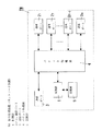
ネットワーク装置である統合管理装置TMは、図1に示すようにそれぞれにLANケーブルを介してサブシステムSSnのコントローラCnが接続される複数の通信ポート2i(i=1,2,…)と、LANケーブルを介してインターネット接続装置MDが接続される通信ポート3と、通信ポート2i,3間の伝送経路を切り換えるとともに通信ポート2i,3間で転送されるパケットの破棄や通信ポート2i又は3の遮断若しくは制限等の処理(以下、パケット処理と呼ぶ。)を実行するパケット処理部4と、CPUを主構成要素としパケット処理部4を制御して伝送経路を切り換えさせる機能(経路切換機能)やパケットに対するウイルスチェックやフィルタリング等を実行する機能(ネットワークセキュリティ機能)、サブシステムの構成管理機能(後述する)等を有する制御部1と、コントローラCnやインターネット接続装置MDのMAC(Media Access Conrol:媒体アクセス制御)アドレスやネットワークアドレス(プライベートのIPアドレス)、各サブシステムSSnに関する制御情報や監視情報を記憶するための記憶部5とを備えている。通信ポート2i,3は、LANケーブルの先端に設けられているRJ−45のモジュラプラグが挿抜自在に接続されるモジュラジャックを具備している。また、パケット処理部4は多数のスイッチ要素を具備し、制御部1の経路切換機能によってスイッチ要素が駆動されることにより任意の1つの通信ポート2i又は3と他の1乃至複数の通信ポート2i又は3との間の伝送経路を切り換えたり、あるいは制御部1のネットワークセキュリティ機能によって異常(例えば、不正なパケットやネットワークに支障を来すほど大量のパケットの流入または流出)が生じている通信ポート2i又は3を遮断若しくは制限するものである。記憶部5は不揮発性メモリからなり、各通信ポート2iに接続されているコントローラCnや端末装置並びに通信ポート3に接続されているインターネット接続装置MDのMACアドレスやネットワークアドレスを各通信ポート2i,3と対応させて記憶している。但し、通信ポート2i,3に接続されているコントローラCnや端末装置並びにインターネット接続装置MDのMACアドレスを取得する方法については従来周知であるから詳細な説明は省略する。また、各コントローラCnや端末装置のネットワークアドレス、すなわち、プライベート(あるいはローカルとも言う。)のIPアドレスについては、制御部1がDHCP(Dynamic Host Configuration Protocol)を用いて自動的に割り当てるようになっている。但し、DHCPを用いたネットワークアドレスの自動割り当てについても従来周知であるから詳細な説明は省略する。
As shown in FIG. 1, the integrated management device TM, which is a network device, includes a plurality of communication ports 2 i (i = 1, 2,...) To which the controller Cn of the subsystem SSn is connected via a LAN cable. The transmission path between the
制御部1は、通信ポート2i,3からパケット処理部4に入ってくるパケットの送信先のアドレス(MACアドレス)を監視しており、例えば、通信ポート3から入ってきたパケットの送信先のアドレスを記憶部5に記憶しているMACアドレスと照合し、送信先のアドレスと一致するMACアドレスのコントローラCnや端末装置(例えば、コントローラC1)が接続されている通信ポート21と通信ポート3との間にのみ伝送経路が形成されるようにパケット処理部4を制御し、形成された伝送経路を介してパケットを通信ポート21に送り出させている(経路切換機能)。また、制御部1では、通信ポート2i,3を通過するパケットを常時監視し、異常なパケットを破棄したり、あるいは上述のようにパケット処理部4を制御して異常が生じている通信ポート2i又は3を遮断若しくは制限させている(ネットワークセキュリティ機能)。さらに、制御部1はUPnP(ユニバーサル・プラグ・アンド・プレイ)のコントロールポイントの機能を実装しており、後述するようにUPnPにおいてデバイスの検出を行うSSDP(Simple Service Discovery Protocol)を利用してUPnPのデバイスに相当する各コントローラCnを自動的に検出するようになっている。
The
ところで、統合管理装置TMは、合成樹脂成形品からなる箱形のハウジング(図示せず)に上述した各部を収納して構成されているが、当該ハウジングは住宅内の壁面に設置されている住宅用分電盤(住宅盤)に収納可能となっている。但し、当該ハウジングの構造は一例であって、必ずしも住宅盤に収納される必要はない。 By the way, the integrated management device TM is configured by housing the above-described parts in a box-shaped housing (not shown) made of a synthetic resin molded product, and the housing is installed on a wall surface in the house. It can be stored in a distribution board (residential board). However, the structure of the housing is an example, and it is not always necessary to be housed in a housing board.
次に、個々のサブシステムSSnについて説明する。 Next, each subsystem SSn will be described.
サブシステムSS1は、照明器具や空調機器(エアコン)並びに電気錠等の住宅設備(設備機器)Xm(m=1,2,…)と、設備機器Xmの制御並びに監視を行うコントローラ(以下、設備機器コントローラと呼ぶ。)C1と、住宅における使用電流を計測する電流計測装置Dとを備えている。ここで、設備機器コントローラC1は、自己の配下にある設備機器X1〜X4の名称並びに動作状態を文字や記号で表示するための多数のウェブページ(ウェブページ群)を保持しており、端末装置からの要求に応じて当該ウェブページ群の中から適切なウェブページを選んで宅内ネットワークを通じて端末装置に提供(配信)する機能(ウェブサーバ機能)を有している。 The sub-system SS1 includes a lighting equipment, an air conditioner (air conditioner), a housing facility (equipment device) Xm (m = 1, 2,...) Such as an electric lock, and a controller (hereinafter, facilities) that controls and monitors the facility device Xm. It is referred to as a device controller.) C1 and a current measuring device D that measures a current used in a house. Here, the equipment device controller C1 holds a large number of web pages (web page group) for displaying the names and operation states of the equipment devices X1 to X4 under its control with characters and symbols, and the terminal device. A function (web server function) that selects (applies to) a terminal device through a home network by selecting an appropriate web page from the web page group in response to a request from the user.
また電流計測装置Dは、住宅用分電盤(住宅盤)に収納されている主幹ブレーカに流れ込む電流を計測し、その計測値(使用電流)が予め決められている上限値を超えた場合、設備機器コントローラC1に機器停止(電源オフ)指令を送信するか、あるいは自己の配下にある設備機器X3又はX4の電源をオフさせて電力の使い過ぎを防止する機能(デマンド制御機能)を有している。但し、必ずしも電流計測装置Dに設備機器X3,X4の制御及び監視機能を持たせる必要はなく、設備機器コントローラC1が上記デマンド制御機能を搭載してもよい。また、電流計測装置Dは必須の構成要件ではなく、電流計測装置Dを含まないサブシステムSS1であっても構わない。 Moreover, the current measuring device D measures the current flowing into the main breaker housed in the residential distribution board (house board), and when the measured value (current used) exceeds a predetermined upper limit value, It has a function (demand control function) to send an equipment stop (power off) command to the equipment controller C1 or to turn off the equipment X3 or X4 under its control to prevent excessive use of power. ing. However, the current measuring device D is not necessarily required to have the control and monitoring functions for the equipment devices X3 and X4, and the equipment device controller C1 may be equipped with the demand control function. Further, the current measuring device D is not an essential constituent element, and may be a subsystem SS1 that does not include the current measuring device D.
また、サブシステムSS2は、図2に示すように住宅内における異常発生を検知する1乃至複数種類のセキュリティ機器Y1,Y2と、各セキュリティ機器Y1,Y2の検知情報を収集するセキュリティ受信器SRと、セキュリティ受信器SRが収集した検知情報を受け取るとともに受け取った当該検知情報を応答メッセージにより宅内ネットワークを通じて伝送するコントローラ(以下、セキュリティコントローラと呼ぶ。)C2とで構成されるセキュリティシステムである。 Further, as shown in FIG. 2, the subsystem SS2 includes one or more types of security devices Y1 and Y2 that detect the occurrence of abnormality in the house, and a security receiver SR that collects detection information of each security device Y1 and Y2. The security system includes a controller (hereinafter referred to as a security controller) C2 that receives detection information collected by the security receiver SR and transmits the received detection information through a home network using a response message.
セキュリティ機器Y1は、例えば、人体から放射される熱線を検出することによる監視領域内への人の侵入検知や、窓に設置されているクレセント錠の施解錠検知、窓の開閉検知等を行う防犯用のセンサを具備し、センサで異常(人の侵入やクレセント錠の解錠等)を検知したときに当該検知情報を無線信号(若しくは有線信号)でセキュリティ受信器SRに送信する機能を有している。また、セキュリティ機器Y2は、煙や熱を検出することによる火災検知や都市ガスあるいはLPガスを検出することによるガス漏れ検知等を行う防災用のセンサを具備し、センサで異常(火災発生やガス漏れ等)を検知したときに当該検知情報を無線信号(若しくは有線信号)でセキュリティ受信器SRに送信する機能を有している。 For example, the security device Y1 is a crime prevention device that detects a human intrusion into a monitoring area by detecting a heat ray radiated from a human body, detects whether a crescent lock installed in a window is unlocked, and detects whether a window is opened or closed. Has a function to transmit the detection information to the security receiver SR as a wireless signal (or wired signal) when an abnormality (intrusion of a person, unlocking of a crescent lock, etc.) is detected by the sensor. ing. The security device Y2 is equipped with a sensor for disaster prevention that detects fire by detecting smoke and heat, and gas leak detection by detecting city gas or LP gas. A function of transmitting the detection information to the security receiver SR by a wireless signal (or a wired signal) when a leak is detected.
セキュリティ受信器SRは、セキュリティ機器Y1,Y2から送信された無線信号(若しくは有線信号)を受信することで検知情報を収集し、さらに当該検知情報に対応した処理、例えば、火災やガス漏れあるいは不審者の侵入等の異常発生を家人に知らせるために警報音を鳴動する処理を行うとともに検知された異常の種類や場所等の検知情報を無線信号(若しくは有線信号)でセキュリティコントローラC2に送信する処理を行う。ここで、セキュリティ機器Y1,Y2には固有の識別符号(ID)が割り当てられており、セキュリティ受信器SRでは当該識別符号によって個々のセキュリティ機器Y1,Y2の検知情報を識別可能となっている。また、セキュリティ受信器SRは、上述のようにセキュリティ機器Y1,Y2から検知情報を収集する警戒状態と検知情報を収集しない非警戒状態の2つの動作状態があり、例えば、ワイヤレス送信機(図示せず)から送信されるワイヤレス信号によって警戒状態と非警戒状態の2つの動作状態が択一的に切り換えられる。但し、ワイヤレス送信機にも固有の識別符号が割り当てられており、予め登録されている識別符号以外の識別符号が割り当てられたワイヤレス送信機では動作状態の切換が行えないようになっている。 The security receiver SR collects detection information by receiving wireless signals (or wired signals) transmitted from the security devices Y1 and Y2, and further processes corresponding to the detection information, for example, fire, gas leakage or suspicious Processing to sound an alarm sound to inform the family of the occurrence of an abnormality such as an intruder, and to transmit detection information such as the type and location of the detected abnormality to the security controller C2 by wireless signal (or wired signal) I do. Here, a unique identification code (ID) is assigned to the security devices Y1 and Y2, and the security receiver SR can identify the detection information of the individual security devices Y1 and Y2 by the identification code. Further, the security receiver SR has two operation states, ie, a warning state in which detection information is collected from the security devices Y1 and Y2 and a non-warning state in which detection information is not collected as described above. For example, a wireless transmitter (not shown) 2) are selectively switched between a warning state and a non-warning state. However, a unique identification code is also assigned to the wireless transmitter, and the wireless transmitter to which an identification code other than the previously registered identification code is assigned cannot switch the operating state.
セキュリティコントローラC2は、セキュリティ受信器SRから受け取った検知情報を応答メッセージとして宅内ネットワーク(あるいは宅内ネットワークと外部ネットワーク)を通じて端末装置に送信する機能(警報機能)や、端末装置から制御要求のメッセージを受け取ったときにセキュリティ受信器SRにコマンド(切換指令)を送信してセキュリティ受信器SRの動作状態(警戒状態又は非警戒状態)を切り換えたり、あるいはセキュリティ受信器SRによる警報音の鳴動を停止させたり、端末装置から監視要求のメッセージを受け取ったときにセキュリティ受信器SRにコマンドを送信してセキュリティ受信器SRの動作状態(警戒状態又は非警戒状態)を通知させるとともに、制御要求や監視要求に対する応答(セキュリティ受信器SRの動作状態や警報音の鳴動状況等)のメッセージを要求メッセージの送信元である端末装置に向けて送信させる機能(制御監視機能)を有する。また、セキュリティコントローラC2は、自己の配下にあるセキュリティ受信器SRの動作状態等を文字や記号で表示するための多数のウェブページ(ウェブページ群)を保持しており、端末装置からの要求に応じて当該ウェブページ群の中から適切なウェブページを選んで宅内ネットワークを通じて端末装置に提供(配信)する機能(ウェブサーバ機能)を有している。 The security controller C2 receives the detection information received from the security receiver SR as a response message to the terminal device through the home network (or home network and external network) (alarm function), and receives a control request message from the terminal device A command (switching command) is sent to the security receiver SR to switch the operating state (warning state or non-warning state) of the security receiver SR, or the alarm sound from the security receiver SR is stopped. When a monitoring request message is received from the terminal device, a command is sent to the security receiver SR to notify the operating state (warning state or non-warning state) of the security receiver SR, and a response to the control request or monitoring request (Receiving security Function to transmit a message towards the terminal device which is the source of the request message vessels sounding status of operating conditions or audible alarm SR, etc.) with a (control monitoring). In addition, the security controller C2 holds a large number of web pages (web page group) for displaying the operating state of the security receiver SR under its control with characters and symbols, and responds to requests from the terminal device. Accordingly, it has a function (web server function) of selecting (appropriating) an appropriate web page from the web page group and providing (distributing) it to the terminal device through the home network.
サブシステムSS3は、図2に示すように住戸外に設置されるカメラ付きドアホン子器(以下、ドアホン子器と略す。)DSと、人体から放射される熱線を検出することで監視領域内への人の侵入を検知するとともに当該侵入検知時に監視領域を撮像するセンサカメラSCと、住戸内に設置されてドアホン子器DSとの間で通話する通話機能並びにドアホン子器DS並びにセンサカメラSCで撮像された画像を表示する機能を有するインターホン親機IMと、インターホン親機IMよりドアホン子器DSやセンサカメラSCで撮像された画像を受け取るとともに受け取った当該画像を外部ネットワークを通じてセンタ装置SVに伝送するコントローラ(以下、画像転送コントローラと呼ぶ。)C3とで構成されるインターホンシステムである。 As shown in FIG. 2, the sub-system SS3 detects a camera-equipped doorphone slave unit (hereinafter abbreviated as a doorphone slave unit) DS installed outside the dwelling unit and a heat ray radiated from the human body to enter the monitoring area. A call function for making a call between the sensor camera SC that detects the intrusion of a person and picks up an image of the monitoring area at the time of the intrusion detection, and the intercom unit DS installed in the dwelling unit, and the intercom unit DS and the sensor camera SC. Interphone master unit IM having a function of displaying a captured image, and receiving an image captured by door phone slave unit DS and sensor camera SC from interphone master unit IM and transmitting the received image to center device SV through an external network Controller (hereinafter referred to as an image transfer controller) C3.
ドアホン子器DSは、通話用のマイクロホン並びにスピーカや来訪者を撮像するためのカメラを具備し、マイクロホンで集音した通話音声を通話線を介してインターホン親機IMに伝送し且つインターホン親機IMから通話線を介して伝送される通話音声をスピーカから鳴動させる通話機能と、呼出釦が押操作されたときに通話線を介してインターホン親機IMに呼出信号を送信する呼出機能と、カメラ(例えば、動画像を出力するCCDカメラ)で撮像された画像を周波数変調して通話音声に多重化することで通話線を介してインターホン親機IMに伝送する画像伝送機能とを有している。また、センサカメラSCは、人体から放射される熱線を検出することで監視領域内への人の侵入を検知する熱線センサや動画像を出力するCCDカメラ等を具備し、信号線を介して監視領域の画像をドアホン子器DSに伝送する機能を有している。なお、ドアホン子器DSに伝送された画像は通話線を介してインターホン親機IMに転送される。 The intercom DS is equipped with a microphone for calling, a speaker and a camera for imaging a visitor, transmits the call voice collected by the microphone to the interphone base unit IM via the telephone line, and interphone base unit IM A call function for ringing the call voice transmitted from the speaker via the call line, a call function for sending a call signal to the intercom base unit IM via the call line when the call button is pressed, and a camera ( For example, it has an image transmission function of transmitting an image captured by a CCD camera (outputting a moving image) to the interphone master unit IM via a communication line by frequency-modulating and multiplexing the image into a call voice. In addition, the sensor camera SC includes a heat ray sensor that detects the intrusion of a person into the monitoring area by detecting a heat ray emitted from the human body, a CCD camera that outputs a moving image, and the like, and is monitored via a signal line. It has a function of transmitting the image of the area to the door phone slave unit DS. In addition, the image transmitted to the door phone slave unit DS is transferred to the interphone master unit IM via the telephone line.
一方、インターホン親機IMは、全体の制御を行うマイコンや音声処理用のDSP、通話用のマイクロホン並びにスピーカや画像表示用の液晶ディスプレイ、画像や通話音声を記録する不揮発性の半導体メモリ等を具備し、呼出信号を受信したときにスピーカから呼出音を鳴動する機能と、呼出音の鳴動中又は鳴動後の一定時間内に応答釦が押操作されたときにドアホン子器DSとの間に通話線を介した通話路を形成して通話音声を授受する通話機能と、通話中にドアホン子器DSで撮像され且つ伝送される画像(通話相手を撮像した画像)を周波数復調して液晶ディスプレイに表示する機能と、通話中以外でドアホン子器DS又はセンサカメラSCで撮像され且つドアホン子器DSから伝送される画像を周波数復調して液晶ディスプレイに表示する機能(画像モニタ機能)と、留守録設定中に呼出信号を受信した場合に通話線を介してドアホン子器DSから伝送される画像並びに通話音声を不揮発性の半導体メモリに記録する機能(留守録機能)と、センサカメラSCで撮像され且つドアホン子器DSより通話線を介して伝送された画像を不揮発性の半導体メモリに記録する機能(センサカメラ録画機能)と、ドアホン子器DSで特定の操作(例えば、呼出釦の長押し)が行われた場合に通常の呼出音と区別可能な通知音で家人の帰宅を通知する機能(帰宅通知機能)とを有している。 On the other hand, the interphone base unit IM includes a microcomputer for controlling the whole, a DSP for voice processing, a microphone for calling, a speaker, a liquid crystal display for image display, a nonvolatile semiconductor memory for recording images and calling voice, and the like. When a call signal is received, a call is made between the speaker and the door phone cordless handset DS when the answer button is pressed during a certain period of time after or during the ringing of the ringing tone. A call function for transferring a call voice by forming a call path via a line, and an image picked up and transmitted by the intercom DS during the call (an image of the call partner) are frequency-demodulated to a liquid crystal display The function to display and the image captured by the doorphone slave unit DS or the sensor camera SC and transmitted from the doorphone slave unit DS when not in a call are frequency-demodulated to the liquid crystal display. A function to display (image monitor function) and a function to record an image and call voice transmitted from the intercom cordless handset DS via a call line in a nonvolatile semiconductor memory when a call signal is received during an answering machine setting ( An answering machine function), a function of recording an image captured by the sensor camera SC and transmitted from the doorphone slave unit DS via a telephone line in a non-volatile semiconductor memory (sensor camera recording function), and a doorphone slave unit DS It has a function (notification function for returning home) of notifying the return of a householder with a notification sound that can be distinguished from a normal ringing sound when a specific operation (for example, long press of a call button) is performed.
而して、来訪者がドアホン子器DSの呼出釦を押操作すると、常時有効である呼出機能によってインターホン親機IMに通話線を介して呼出信号が伝送され、インターホン親機IMにおいてスピーカから呼出音が鳴動されるとともに、通話線を介してインターホン親機IMから電源が供給されることでドアホン子器DSの画像伝送機能が有効になり、ドアホン子器DSのカメラで撮像された画像がインターホン親機IMの液晶ディスプレイに表示される。そして、液晶ディスプレイに表示された画像で来訪者を確認した家人がインターホン親機IMの応答釦を押操作すれば、通話機能によりドアホン子器DSとの間に通話線を介した通話路が形成されてインターホン親機IMとドアホン子器DSとの間においてスピーカとマイクロホンを使った拡声通話(ハンズフリー通話)が可能になるとともに、通話中においてはインターホン親機IMの液晶ディスプレイにドアホン子器DSから伝送される画像を表示させることが可能になる。但し、インターホン親機IMとドアホン子器DSとの間の拡声通話並びに画像伝送は、応答釦が押操作されてから所定時間が経過するか若しくは再度応答釦が押操作されたときに終了する。また、監視領域における不審者の侵入を検知するとセンサカメラSCが撮像した監視領域の画像がドアホン子器DS経由でインターホン親機IMに伝送されて液晶ディスプレイに表示される。但し、上述のような機能を有するインターホン親機IM、ドアホン子器DS、センサカメラSCについては、従来周知であるから詳細な構成についての図示並びに説明を省略する。 Thus, when the visitor presses the call button of the door phone DS, a call signal is transmitted to the interphone base unit IM via the telephone line by the call function that is always effective, and the interphone base unit IM calls from the speaker. When the sound is generated and the power is supplied from the interphone master unit IM via the communication line, the image transmission function of the door phone slave unit DS becomes effective, and the image captured by the camera of the door phone slave unit DS is displayed as the interphone. It is displayed on the liquid crystal display of base unit IM. Then, if a householder who confirms the visitor with the image displayed on the liquid crystal display presses the response button of the interphone master unit IM, a call path is formed between the doorphone slave unit DS and the doorphone cord DS by the call function. As a result, a loudspeaker call (hands-free call) using a speaker and a microphone can be performed between the interphone master unit IM and the door phone slave unit DS. It is possible to display an image transmitted from the network. However, the voice call and the image transmission between the interphone master unit IM and the door phone slave unit DS are ended when a predetermined time elapses after the response button is pressed or when the response button is pressed again. When the intrusion of the suspicious person in the monitoring area is detected, the image of the monitoring area captured by the sensor camera SC is transmitted to the interphone master unit IM via the doorphone slave unit DS and displayed on the liquid crystal display. However, since the interphone master unit IM, the door phone slave unit DS, and the sensor camera SC having the functions as described above are well known in the art, illustration and description of detailed configurations are omitted.
画像転送コントローラC3は、ドアホン子器DS並びにセンサカメラSCからインターホン親機IMに伝送された画像データ及び通話音声データをインターホン親機IMから受け取るとともに受け取ったデータを所定の圧縮方式(例えば、動画像であればMPEG4、静止画像であればJPEG、音声であればMP3など)で圧縮した後に応答メッセージとして宅内ネットワーク及び外部ネットワークを通じてセンタ装置SVに転送する機能(転送機能)と、インターホン親機IMの留守録機能が有効であるときにインターホン親機IMが画像及び通話音声を記録した旨を宅内ネットワーク並びに外部ネットワークを通じてセンタ装置SVに通知する機能(来客通知機能)と、帰宅通知機能によってインターホン親機IMに家人の帰宅が通知されたときに宅内ネットワーク並びに外部ネットワークを通じてセンタ装置SVに帰宅通知の応答メッセージを転送する機能(帰宅通知転送機能)とを有する。また、画像転送コントローラC3は、メモリに記録している画像の一覧等を開示する多数のウェブページ(ウェブページ群)を保持しており、端末装置からの要求に応じて適切なウェブページを選んで宅内ネットワークを通じて端末装置に提供(配信)する機能(ウェブサーバ機能)を有している。 The image transfer controller C3 receives image data and voice data transmitted from the interphone master unit IM from the intercom master unit DS and the sensor camera SC to the interphone master unit IM and receives the received data in a predetermined compression method (for example, a moving image). And MPEG4, JPEG for still images, MP3 for audio, etc., and then a function (transfer function) for transferring a response message to the center device SV through the home network and the external network. A function for notifying the center device SV that the interphone master unit IM has recorded an image and a voice call when the answering machine function is valid (visitor notification function) through the home network and the external network, and a home return notification function, Notification of IM And a function of transferring a response message returned home notifies the center apparatus SV via the home network and an external network (return home notification forwarding function) when. The image transfer controller C3 holds a large number of web pages (web page group) disclosing a list of images recorded in the memory, and selects an appropriate web page in response to a request from the terminal device. The function (web server function) of providing (distributing) to the terminal device through the home network.
次に、表示制御装置CVについて説明する。表示制御装置CVは住宅内の壁面に埋込配設されるものであって、図3に示すようにマイコンを主構成要素とするマイコン部50と、宅内ネットワークのLANケーブルが接続されマイコン部50と宅内ネットワークのインタフェースを行うLANインタフェース部51と、液晶ディスプレイ52a並びにLED(図示せず)とそれらのドライバ回路を有する表示部52と、押釦スイッチや液晶ディスプレイ52aの画面上に配設されるタッチパネルを有して操作入力を受け付ける操作部53と、マイコンで実行するプログラムや種々のデータを記憶するメモリ部54と、スピーカとスピーカの駆動回路を有するスピーカ部55とを備えている。また、図示は省略しているが、商用電源から所望の直流電源を作成してマイコン部50やその他の各部に動作電源を供給するための電源回路も備えている。マイコン部50にはウェブブラウザが実装されており、各コントローラCn等から提供されるウェブページ並びに予めメモリ部54に記憶しているウェブページ(以下、内蔵ウェブページと呼ぶ。)をウェブブラウザで再生して表示部52の液晶ディスプレイ52aに表示するとともに、操作部53のタッチパネルが操作された位置と液晶ディスプレイ52aに表示されているアイコン等との位置関係に応じた操作入力を受け付ける。すなわち、マイコン部50がウェブブラウザ手段であり、操作部53が操作入力受付手段である。また、メモリ部54には予め警報音や音声メッセージのデータが圧縮して格納されており、マイコン部50が必要に応じてメモリ部54から読み出したデータを伸長してスピーカ部55に出力すれば、前記警報音や音声メッセージがスピーカから鳴動される。
Next, the display control device CV will be described. The display control device CV is embedded in a wall surface in a house. As shown in FIG. 3, a
また本実施形態においては、自ら撮像した画像を宅内ネットワーク経由で配信する機能(ウェブサーバ機能)を有した、いわゆるウェブカメラWCがLANケーブルを介して統合管理装置TMに接続されている(図2参照)。かかるウェブカメラWCは従来周知であって、撮像した画像を所定の圧縮方式(例えば、動画像であればMPEG4、静止画像であればJPEGなど)で圧縮してネットワークを通じて配信したり、ネットワークを通じてパンやチルトの遠隔制御が可能である。 In this embodiment, a so-called web camera WC having a function (web server function) for distributing an image captured by itself via a home network is connected to the integrated management apparatus TM via a LAN cable (FIG. 2). reference). Such a web camera WC is well known in the art and compresses a captured image by a predetermined compression method (for example, MPEG4 for a moving image, JPEG for a still image, etc.) and distributes it through a network, or pans through a network. And remote control of tilt.
ところで本実施形態においては、統合管理装置TMにもウェブサーバ機能が搭載されており、各コントローラCnがウェブサーバ機能によって提供するウェブページ群への入り口となるウェブページ(いわゆるポータルサイト)を作成し、宅内ネットワークを通じて住宅内の端末装置(パソコンPCや表示制御装置CV)に提供(配信)している。例えば、表示制御装置CVの液晶ディスプレイ52aには、通常、統合管理装置TMで作成された前記ポータルサイトが表示されている。このポータルサイトでは、各コントローラCnで提供されるウェブコンテンツ(各サブシステムSSnのウェブページ群)へのリンクがアイコンで表示されており、何れかのアイコン上でタッチパネルが操作されれば、当該アイコンで表示されたリンク先のURL(各コントローラCnが保有するウェブページ群のIPアドレス)に対して表示制御装置CVからウェブコンテンツの送信要求メッセージが送信される。そして、送信要求メッセージを受信したコントローラCnが自己の保有するウェブページ群の中から指定されたウェブページを表示制御装置CVに対して送信すれば、前記ポータルサイトに代わって当該コントローラCnのウェブページが液晶ディスプレイ52aに表示される。 By the way, in this embodiment, the integrated management device TM also has a web server function, and each controller Cn creates a web page (so-called portal site) that serves as an entrance to a web page group provided by the web server function. And provided (distributed) to terminal devices (personal computer PC and display control device CV) in the house through the home network. For example, the portal site created by the integrated management device TM is usually displayed on the liquid crystal display 52a of the display control device CV. In this portal site, a link to web content (web page group of each subsystem SSn) provided by each controller Cn is displayed as an icon, and if the touch panel is operated on any of the icons, the icon A web content transmission request message is transmitted from the display control device CV to the link destination URL (the IP address of the web page group held by each controller Cn) displayed in. Then, if the controller Cn that has received the transmission request message transmits a web page designated from among a group of web pages held by itself to the display control device CV, the web page of the controller Cn instead of the portal site. Is displayed on the liquid crystal display 52a.
次に、表示制御装置CVを使って設備機器Xmの制御並びに監視を行う場合の動作を、図4のシーケンス図を参照して説明する。 Next, the operation in the case of controlling and monitoring the equipment device Xm using the display control device CV will be described with reference to the sequence diagram of FIG.
まず、操作部53の操作釦53aが押操作されるとマイコン部50がLANインタフェース部51より統合管理装置TMに対してポータルサイトの送信要求メッセージを送信する(1)。当該メッセージを受け取った統合管理装置TMの制御部1は、サブシステムSS1〜SS3のウェブページ群へのリンクを示すアイコンや個々のサブシステムSS1〜SS3の名称を示す文字等を表示するポータルサイトを予め作成して記憶部5に記憶しており、当該メッセージを受け取ったときに記憶部5からポータルサイトのデータを読み出して送信要求元の表示制御装置CVへ送信する(2)。
First, when the operation button 53a of the
表示制御装置CVでは、統合管理装置TMから受け取ったウェブページのデータ(ファイル)をマイコン部50で実行するウェブブラウザで開くことにより、液晶ディスプレイにポータルサイトを表示する(3)。そして、サブシステムSS1のアイコン上でタッチパネルが操作されれば(4)、当該アイコンで表示されたリンク先のURL(設備機器コントローラC1が保有するウェブページ群のIPアドレス)に対して、前記ウェブブラウザによってウェブページの送信要求メッセージが送信される(5)。そして、送信要求メッセージを受信した設備機器コントローラC1が自己の保有するウェブページのデータを表示制御装置CVに送信すれば(6)、マイコン部50で実行するウェブブラウザで当該データ(ファイル)を開くことによりサブシステムSS1のウェブページが表示部52の液晶ディスプレイに表示される(7)。このウェブページでは、サブシステムSS1に含まれる設備機器X1〜X4の名称と設置場所(例えば、「リビングのエアコン」,「リビングの照明」など)を示した文字、各設備機器X1〜X4の動作状態を示す文字、各設備機器X1〜X4の動作状態を反転させる操作に対応したボタン等が表示され、これらのボタンに各々他のウェブページがリンクしている。従って、ウェブページに表示される情報から各設備機器X1〜X4の動作状態を監視(確認)することができる(8)。
The display control device CV displays the portal site on the liquid crystal display by opening the web page data (file) received from the integrated management device TM with a web browser executed by the microcomputer unit 50 (3). Then, if the touch panel is operated on the icon of the subsystem SS1 (4), the web address is linked to the link destination URL (IP address of the web page group held by the equipment controller C1) displayed by the icon. A web page transmission request message is transmitted by the browser (5). Then, when the equipment controller C1 that has received the transmission request message transmits the data of the web page held by itself to the display control device CV (6), the data (file) is opened by the web browser executed by the
ここで、何れかの設備機器Xmの動作状態を反転させる制御、例えば、現在点灯している照明器具(設備機器X2)を消灯させる制御を行う場合、ウェブページにおいて設備機器X4の動作状態を反転させる操作に対応したボタン上でタッチパネルを操作する(9)。すると、前記ウェブブラウザによって当該ボタンが操作されたことを示すメッセージ、つまり、照明器具(設備機器X2)の消灯制御を要求するメッセージ(要求メッセージ)が宅内ネットワークを通じて設備機器コントローラC1のネットワークアドレス宛に送信される(10)。そして、この要求メッセージを受け取った設備機器コントローラC1が照明器具(設備機器X2)を消灯する(11)。その後、設備機器コントローラC1は照明器具(設備機器X2)の消灯に対応したウェブページのデータを表示制御装置CVに送信し(12)、表示制御装置CVのマイコン部50で実行するウェブブラウザで当該データ(ファイル)を開くことによりサブシステムSS1の他のウェブページが表示部52の液晶ディスプレイ52aに表示される(13)。当該ウェブページでは、照明器具(設備機器X2)の動作状態が点灯から消灯に変更されている。但し、何らかの原因で設備機器Xmの制御に失敗した場合、設備機器コントローラC1が制御に失敗した旨の応答メッセージを作成して表示制御装置CVに送信し、表示制御装置CVの表示部52(液晶ディスプレイ52a)にエラーメッセージ(要求された設備機器Xmの制御に失敗した旨の文字)が表示される。
Here, in the case of performing control for reversing the operating state of any of the equipment devices Xm, for example, control for turning off the lighting equipment (equipment device X2) that is currently lit, the operation state of the equipment device X4 is reversed on the web page. The touch panel is operated on the button corresponding to the operation to be performed (9). Then, a message indicating that the button has been operated by the web browser, that is, a message (request message) for requesting to turn off the lighting device (facility device X2) is sent to the network address of the facility device controller C1 through the home network. It is transmitted (10). Then, the equipment controller C1 that has received this request message turns off the luminaire (facility equipment X2) (11). After that, the equipment controller C1 transmits web page data corresponding to the turn-off of the lighting fixture (facility equipment X2) to the display controller CV (12), and the web browser is executed by the
次に、携帯型の端末装置(例えば、携帯電話機MP)を使って住宅の外から設備機器Xmの制御並びに監視を行う場合の動作を、図10のシーケンス図を参照して説明する。ここで、外部ネットワーク(インターネット)に対して各コントローラCnのウェブサーバ機能がポートを常時開放していると、例えば、悪意を持った侵入者によってシステムに異常を来す虞が高くなるので、本実施形態においては、各コントローラCnのウェブサーバ機能が通常はポートを閉じつつセンタ装置SVに対して定期的にポーリングを行い、携帯型の端末装置から受け取った要求メッセージがセンタ装置SVに保持されていれば、当該要求メッセージの宛先のコントローラCnによるポーリング時にセンタ装置SVから要求メッセージを転送することで宅内ネットワークを保護している。 Next, the operation in the case of controlling and monitoring the equipment device Xm from outside the house using a portable terminal device (for example, the mobile phone MP) will be described with reference to the sequence diagram of FIG. Here, if the web server function of each controller Cn always opens a port to the external network (Internet), for example, there is a high possibility that a malicious intruder will cause an abnormality in the system. In the embodiment, the web server function of each controller Cn normally polls the center device SV while closing the port, and the request message received from the portable terminal device is held in the center device SV. Then, the home network is protected by transferring the request message from the center apparatus SV at the time of polling by the controller Cn that is the destination of the request message.
上述のように各コントローラCnからセンタ装置SVに対して定期的にポーリングが行われ、センタ装置SVに携帯電話機MPからの要求メッセージが保持されていなければ、センタ装置SVからは単に肯定応答(ACK)がコントローラCnに返信されるだけである。ここで、家人が携帯電話機MPを使って要求メッセージ(例えば、照明器具の動作状態の監視要求メッセージ)をセンタ装置SVに送信し(1)、当該監視要求メッセージがセンタ装置SVで保持された後に設備機器コントローラC1からポーリングされると(2)、センタ装置SVは携帯電話機MPから受け取って保持していた前記監視要求メッセージを設備機器コントローラC1に対して送信(転送)する(3)。この監視要求メッセージを受け取った設備機器コントローラC1では、照明器具(設備機器X2)の現在の動作状態(例えば、点灯)を示す監視応答メッセージを作成してセンタ装置SVに返信する(4)。当該監視応答メッセージはセンタ装置SVから携帯電話機MPに転送され(5)、携帯電話機MPの液晶画面にセンサ装置SVから転送された監視応答メッセージが表示されることで照明器具の動作状態(点灯)が確認できる。 As described above, each controller Cn periodically polls the center device SV, and if the center device SV does not hold a request message from the mobile phone MP, the center device SV simply receives an acknowledgment (ACK). ) Is simply returned to the controller Cn. Here, the householder uses the mobile phone MP to send a request message (for example, a monitoring request message for the operating state of the lighting fixture) to the center device SV (1), and after the monitoring request message is held by the center device SV. When polled from the equipment controller C1 (2), the center apparatus SV transmits (transfers) the monitoring request message received and held from the mobile phone MP to the equipment controller C1 (3). The equipment controller C1 that has received this monitoring request message creates a monitoring response message indicating the current operating state (for example, lighting) of the luminaire (facility equipment X2) and sends it back to the center apparatus SV (4). The monitoring response message is transferred from the center device SV to the cellular phone MP (5), and the monitoring response message transferred from the sensor device SV is displayed on the liquid crystal screen of the cellular phone MP, so that the operating state (lighting) of the lighting fixture is displayed. Can be confirmed.
また、家人が携帯電話機MPを使って要求メッセージ(例えば、照明器具を消灯する制御要求メッセージ)をセンタ装置SVに送信し(6)、当該制御要求メッセージがセンタ装置SVで保持された後に設備機器コントローラC1からポーリングされると(7)、センタ装置SVは携帯電話機MPから受け取って保持していた前記制御要求メッセージを設備機器コントローラC1に対して送信(転送)する(8)。この制御要求メッセージを受け取った設備機器コントローラC1が照明器具(設備機器X2)を消灯する(9)。その後、設備機器コントローラC1が照明器具(設備機器X2)を消灯したことを示す制御応答メッセージを作成してセンタ装置SVに返信する(10)。当該制御応答メッセージはセンタ装置SVから携帯電話機MPに転送され(11)、携帯電話機MPの液晶画面にセンサ装置SVから転送された制御応答メッセージが表示されることで照明器具が消灯したことが確認できる。但し、制御要求メッセージを送信してから制御応答メッセージが返信されるまでに相当の時間(例えば、数分間)を要する場合、制御要求メッセージを受け取った旨のメッセージをセンタ装置SVから携帯電話機MPに送信することが望ましい。 Further, the householder transmits a request message (for example, a control request message for turning off the lighting fixture) to the center apparatus SV using the mobile phone MP (6), and the equipment is stored after the control request message is held in the center apparatus SV. When polled from the controller C1 (7), the center apparatus SV transmits (transfers) the control request message received and held from the mobile phone MP to the equipment device controller C1 (8). The equipment controller C1 that has received this control request message turns off the lighting equipment (facility equipment X2) (9). Thereafter, the equipment device controller C1 creates a control response message indicating that the lighting equipment (facility equipment X2) is turned off, and sends it back to the center apparatus SV (10). The control response message is transferred from the center device SV to the mobile phone MP (11), and it is confirmed that the lighting fixture is turned off by displaying the control response message transferred from the sensor device SV on the liquid crystal screen of the mobile phone MP. it can. However, when it takes a considerable time (for example, several minutes) from sending the control request message to returning the control response message, a message indicating that the control request message has been received is sent from the center device SV to the mobile phone MP. It is desirable to send.
次に、セキュリティシステムSS2において、セキュリティコントローラC2がセキュリティ受信器SRから異常発生(例えば、火災やガス漏れの発生あるいは不審者の侵入など)を示す検知情報を取得した場合の動作を、図5のシーケンス図を参照して説明する。 Next, in the security system SS2, the operation when the security controller C2 obtains detection information indicating occurrence of an abnormality (for example, occurrence of fire or gas leakage or intrusion of a suspicious person) from the security receiver SR is shown in FIG. This will be described with reference to a sequence diagram.
何れかのセキュリティ機器Y1,Y2で異常が検出され、セキュリティコントローラC2がセキュリティ受信器SRから異常発生の検知情報を取得すると(1)、セキュリティコントローラC2は当該検知情報を含む応答メッセージ(以下、連携メッセージと呼ぶ。)を作成して宅内ネットワーク内に一斉同報(ブロードキャスト)する(2)とともに、センタ装置SVにも異常発生通報のためのメッセージを送信する(3)。 When an abnormality is detected in any of the security devices Y1 and Y2, and the security controller C2 acquires detection information of the occurrence of the abnormality from the security receiver SR (1), the security controller C2 sends a response message (hereinafter referred to as cooperation) (Referred to as a message) and broadcast (broadcast) in the home network (2), and also send a message to the center device SV to report the occurrence of an abnormality (3).
前記連携メッセージを受け取った表示制御装置CVでは、マイコン部50が受け取った連携メッセージに含まれる検知情報から発生した異常の内容(例えば、火災やガス漏れの発生あるいは不審者の侵入など)を判断し、その内容に応じた警報音(例えば、「火災が発生しました。すぐに避難してください。」あるいは「不審者が侵入しました。」などの音声メッセージ)をスピーカ部55に鳴動させるとともに、異常の内容に応じた警報表示(例えば、「○○で火災が発生しました。」あるいは「××に不審者が侵入しました。」などのメッセージ)を表示部52の液晶ディスプレイ52aに表示させる(4)。
In the display control device CV that has received the cooperation message, the
また、センタ装置SVでは、セキュリティコントローラC2から受け取った異常発生の通報メッセージを、予め登録されている携帯電話機MPのメールアドレスに送信することで異常の発生を外出中の家人に通知する(5)。 In addition, the center device SV notifies the householder who is out of the house by sending the report message of the occurrence of abnormality received from the security controller C2 to the mail address of the mobile phone MP registered in advance (5). .
一方、連携メッセージを受け取った他のコントローラ、すなわち、設備機器コントローラC1と画像転送コントローラC3においては、受け取った連携メッセージに含まれる検知情報から発生した異常の内容を判断し、予め決められているルールに則り、必要であれば異常の内容に応じた制御動作を実行する(6)。例えば、火災が発生している場合に設備機器コントローラC1が照明器具を点灯することで避難し易くしすることが可能である。但し、ガス漏れが発生している場合、設備機器Xmの動作状態が切り換えられると電源のオン又はオフに伴って発生した火花が漏れたガスに引火する虞があるので、設備機器コントローラC1では、仮に制御要求メッセージを受け取っても全ての設備機器Xmについての制御を無効とする。 On the other hand, other controllers that have received the cooperation message, that is, the equipment device controller C1 and the image transfer controller C3, determine the content of the abnormality that has occurred from the detection information included in the received cooperation message, and determine a predetermined rule. Accordingly, if necessary, a control operation corresponding to the content of the abnormality is executed (6). For example, when a fire is occurring, the facility equipment controller C1 can turn on the luminaire to facilitate evacuation. However, if a gas leak has occurred, there is a risk that the spark generated when the power source is turned on or off will ignite the leaked gas when the operating state of the equipment device Xm is switched. Even if a control request message is received, control for all the equipment devices Xm is invalidated.
ところで、統合管理装置TMの制御部1が有するネットワークセキュリティ機能では、パソコンPCやウェブカメラWCのような汎用の通信端末については使用者自らがネットワークセキュリティを実施可能であるから、主に各サブシステムSSnのコントローラCnに対するネットワークセキュリティを実施している。ここで、制御部1におけるネットワークセキュリティ機能について、さらに詳しく説明する。
By the way, in the network security function of the
制御部1は、各コントローラCnによる定期的なポーリングに対して返信されるパケットにパケットフィルタリングを行い、送信元IPアドレスがセンタ装置SVのIPアドレス(グローバルIPアドレス)に一致しないときは当該パケットを破棄することにより、センタ装置SVのなりすましによる不正アクセスを防止している。また、各コントローラCnに対する通信帯域を確保するため、制御部1では、汎用の通信端末(例えば、パソコンPC)が大容量のファイルをダウンロードする場合等に当該通信端末が接続されている通信ポート2iの帯域を制限する。さらに、通信ポート2i,3を通過するブロードキャストパケットやエラーパケットの量が所定値を超える場合、制御部1は異常と判断して該当する通信ポート2i,3を遮断又は制限する。さらに、通信ポート2i,3の遮断や制限を実行した場合、制御部1は、遮断又は制限している通信ポート(例えば、22)に割り当てられている名称と当該通信ポート22の遮断又は制限を実行中であることを知らせるメッセージを作成して表示制御装置CVに送信する。そして、表示制御装置CVにおいては、統合管理装置TMから受け取った前記メッセージを表示部52の液晶ディスプレイに表示して利用者(家人)に通信ポート22の異常を知らせるのである。
The
ここで、通信ポート22を特定するための特定情報として従来例のように単なる番号を使った場合、利用者には通信ポート22と当該通信ポート22に接続されている通信端末(コントローラCnや端末装置)との対応が判りづらく、利便性が低くなってしまうが、本実施形態では各通信ポート2i,3に予め任意の名称を割り当てておくことができるから、通信端末と通信ポート2i,3との対応関係を判りやすくなり、従来例に比べて利便性が向上できるものである。例えば、設備機器コントローラC1が接続されている通信ポート2iに「設備機器コントローラ」という名称を割り当てたり、リビングに設置されたウェブカメラWCが接続されている通信ポート2iに「リビング」という名称を割り当てることができる。なお、上述のような通信ポート2iの異常通知だけでなく、例えば、宅内ネットワークに新たに通信端末が追加された場合に、追加された通信端末の種類(例えば、ウェブカメラWCなど)と当該通信端末が接続された通信ポート2iの名称を統合管理装置TMから表示制御装置CVに送信してもよい。例えば、「子供部屋」という名称が割り当てられている通信ポート2iに新たにウェブカメラWCが接続されたとすると、「子供部屋にウェブカメラが接続されました。」というメッセージが表示制御装置CVで表示される。
Here, when using a simple number as in the conventional example as the specific information for specifying the communication port 2 2, the communication terminal to the user connected to the communication port 2 2 and the communication port 2 2 (controller However, in this embodiment, since arbitrary names can be assigned to the
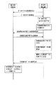
次に、上述のように統合管理装置TMの通信ポート2iに名称を割り当てる動作について、図7のシーケンス図を参照して説明する。 Next, the operation of assigning a name to the communication port 2 i of the integrated management device TM as described above will be described with reference to the sequence diagram of FIG.
まず、操作部53の操作釦53aを押操作してマイコン部50が統合管理装置TMに対してポータルサイトの送信要求メッセージを送信すると(1)、当該メッセージを受け取った統合管理装置TMの制御部1からポータルサイトのデータが表示制御装置CVへ送信される(2)。
First, when the
表示制御装置CVでは、統合管理装置TMから受け取ったウェブページのデータ(ファイル)をマイコン部50で実行するウェブブラウザで開くことにより、液晶ディスプレイにポータルサイトを表示する(3)。そして、ポータルサイトに用意されている名称割当用のアイコン上でタッチパネルが操作(選択)されれば(4)、統合管理装置TMに対して名称割当用ウェブページの送信要求メッセージが送信される(5)。そして、送信要求メッセージを受信した統合管理装置TMの制御部1が名称割当用ウェブページのデータを表示制御装置CVに送信すれば(6)、マイコン部50で実行するウェブブラウザで当該データ(ファイル)を開くことにより名称割当用ウェブページが表示部52の液晶ディスプレイに表示される(7)。
The display control device CV displays the portal site on the liquid crystal display by opening the web page data (file) received from the integrated management device TM with a web browser executed by the microcomputer unit 50 (3). When the touch panel is operated (selected) on the name assignment icon prepared on the portal site (4), a name assignment web page transmission request message is transmitted to the integrated management device TM ( 5). When the
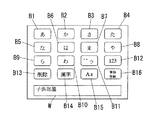
このウェブページでは、既に割り当てられている名称並びに各通信ポート2iに接続されている通信端末(コントローラCnや端末装置など)の種類、さらには各コントローラCnの配下にある住宅設備(設備機器Xmやセキュリティ機器Yn等)の種類と通信ポート2iの対応関係(名称割当情報)が一覧表示されるとともに、名称割当対象の通信ポート2iを選択するためのボタン等が表示され、当該ボタン上でタッチパネルが操作されて何れかの通信ポート(例えば、22)が選択されると(8)、マイコン部50で実行するウェブブラウザでメモリ部54に記憶している名称入力用の内蔵ウェブページを読み出して表示部52の液晶ディスプレイに表示する。この名称入力用内蔵ウェブページでは、操作部53のタッチパネルを使って平仮名や片仮名、英数字等の文字入力を受け付けるためのボタンB1〜B16と入力された文字を表示する入力文字表示領域Wを表示する(図8参照)。例えば、利用者がボタンBk(k=1〜16)上でタッチパネルを操作して「こどもべや」という文字を入力し、さらに「漢字」のボタンB14上でタッチパネルを操作すると、マイコン部50が搭載している日本語入力システムにより「こどもべや」の平仮名が「子供部屋」の漢字に変換される。そして、名称割当のデータ(選択された通信ポート22を示すデータと「子供部屋」の文字列のテキストデータ)が操作部53で入力受付されると(9)、当該名称割当データをマイコン部50がLANインタフェース部51より統合管理装置TMに送信する(10)。
In this web page, the name already assigned and the type of communication terminal (controller Cn, terminal device, etc.) connected to each communication port 2 i , as well as the housing equipment (equipment equipment Xm) subordinate to each controller Cn and as well as the type and correspondence between the communication port 2 i of security equipment Yn, etc.) (name assignment information) is displayed in a list, buttons for selecting a communication port 2 i name assignment object is displayed, on the button When the touch panel is operated to select any communication port (for example, 2 2 ) (8), the name input built-in web page stored in the
一方、統合管理装置TMでは、表示制御装置CVから受け取った名称割当データに基づいて選択された通信ポート22の名称として、名称割当手段たる制御部1が名称割当データに含まれている文字列(「子供部屋」)のテキストデータを割り当てて記憶部5に記憶する(11)。これ以降、通信ポート22で異常が発生した際、制御部1が通信ポート22に割り当てられている名称(「子供部屋」)を記憶部5から読み出し、特定情報として表示制御装置CVに通知するため、通信端末と通信ポート22の対応関係が利用者に判りやすくなる。なお、上述の名称割当処理は表示制御装置CV以外の端末装置、例えば、入力手段(キーボード)と表示手段(ディスプレイ)を有するパソコンPCでも実行可能である。
On the other hand, in the integrated management apparatus TM, as selected communication ports 2 2 name based on the name assigned data received from the display control device CV, string name assigning
また、統合管理装置TMに操作入力受付手段(ディップスイッチやテンキーなど)を設け、この操作入力受付手段で受け付けた名称を制御部1が通信ポート2iの名称に割り当てて記憶部5に記憶するようにしても構わない。この場合、上述のように日本語入力システムを使って任意の文字列を入力することも可能であるが、予め用意した複数の名称候補の中からディップスイッチを使って選択できるようにしても構わない。
Further, the integrated management device TM is provided with operation input receiving means (such as a dip switch and a numeric keypad), and the
あるいは、UPnPのデバイスに相当する通信端末(例えば、ウェブカメラWC等)が通信ポート2iに接続されたとき、コントロールポイントに相当する統合管理装置TMの制御部1が取得するデバイス情報に基づいて、当該通信端末が接続された通信ポート2iに名称を割り当てるようにしても構わない。例えば、リビングに設置されることを想定したウェブカメラWCのデバイス情報に「リビング」というメッセージが含まれている場合、ウェブカメラWCからUPnPによって前記メッセージを受け取った統合管理装置TMの制御部1ではウェブカメラWCが接続された通信ポート2iに「リビング」という名称を割り当てるのである。同様に、サブシステムSSnのコントローラCnがシステムに追加されたときに、UPnPのデバイスに相当するコントローラCnから受け取ったデバイス情報に含まれる機種情報(例えば、「設備機器コントローラ」や「セキュリティコントローラ」などの機種名)に基づいて、統合管理装置TMの制御部1が当該コントローラCnの接続された通信ポート2iの名称としてコントローラCnの機種名を割り当てるようにしてもよい。
Alternatively, based on device information acquired by the
ところで、通信端末には統合管理装置TMの通信ポート2iに接続するLANケーブルが壁裏や天井裏に配線されるもの(コントローラCnの一部や表示制御装置CVなど)と、宅内の壁面に埋込配設されている情報コンセントのモジュラジャックにLANケーブルで接続されるものとがある。かかる情報コンセント100は従来周知であって、図9に示すようにRJ−45のモジュラプラグが挿抜自在に接続されるモジュラジャック101と、引掛形(抜け止め形)コンセント102と、所謂テレビコンセント103並びに電話用のモジュラジャック104とが大角形連用配線器具の取付枠(JIS C8375参照)並びに連用プレート(JIS C8316参照)110を用いて宅内の壁面に埋込配設されてなり、統合管理装置TMの通信ポート2iに接続され且つ壁裏や天井裏に配線されたLANケーブルと、例えば、パソコンPCに接続するLANケーブルとをモジュラジャックMJを介して接続するものである。従って、パソコン(特にノート型のパソコン)PCのように可搬型の端末装置の場合、宅内に幾つか配設されている情報コンセント100の何れに接続することも可能である。そのため、パソコンPCを使って通信ポート2iの名称割当を行う場合、そのパソコンPCが情報コンセント100経由で接続されている通信ポート2iを含む全ての名称を割当可能にすると、意図しない名称が誤って割り当てられてしまう虞がある。
By the way, in the communication terminal, a LAN cable connected to the communication port 2 i of the integrated management device TM is wired behind the wall or the ceiling (a part of the controller Cn, the display control device CV, etc.) and the wall surface in the house. Some are connected to a modular jack of an embedded information outlet by a LAN cable. Such an
そこで、パソコンPCを使って名称割当を行う場合には、統合管理装置TMの制御部1により、名称割当可能な通信ポート2iを当該パソコンPCが接続されている通信ポート2iに限定すれば、上述のように誤って意図しない名称が割り当てられるのを防止できる。具体的には、名称割当用ウェブページにおいて通信ポート2iを選択するためのボタンやアイコンを表示せず、制御部1において、パソコンPCが接続されている通信ポート2iを自動的に名称割当対象に選択すればよい。
Therefore, when assigning names using a personal computer PC, the
なお、情報コンセント100に操作入力受付手段(ディップスイッチやテンキーなど)並びに通信手段(LANインタフェース)を設け、この操作入力受付手段で受け付けた名称のデータを通信手段がモジュラジャック101に接続されているLANケーブルを介して統合管理装置TMに送信し、統合管理装置TMの制御部1において、受け取った名称を当該情報コンセント100が接続されている通信ポート2iの名称に割り当てて記憶部5に記憶するようにしても構わない。
The
TM 統合管理装置(ネットワーク装置)
1 制御部
21〜2n 通信ポート
3 通信ポート
4 パケット処理部
5 記憶部
TM Integrated management device (network device)
1 Control Unit 2 1 to 2 n
Claims (6)
伝送路を介して前記通信端末が接続される複数の通信ポートと、該通信ポートより前記伝送路を介してデータ通信を行う通信手段と、各通信ポートに名称を割り当てる名称割当手段とを備えたことを特徴とするネットワーク装置。 A network device constituting a communication system together with a plurality of communication terminals installed in a house,
A plurality of communication ports to which the communication terminal is connected via a transmission line; a communication unit that performs data communication from the communication port via the transmission line; and a name assignment unit that assigns a name to each communication port. A network device.
前記名称割当手段は、前記操作入力受付手段で受け付けた操作入力に応じた名称を割り当てることを特徴とする請求項1記載のネットワーク装置。 Comprising an operation input receiving means for receiving an operation input;
2. The network device according to claim 1, wherein the name assigning means assigns a name corresponding to the operation input received by the operation input receiving means.
前記情報コンセントは、操作入力を受け付けるとともに当該操作入力に応じたデータを前記ネットワーク装置に送信し、
前記名称割当手段は、前記情報コンセントから送信され前記通信手段で受信したデータに応じた名称を割り当てることを特徴とする通信システム。 A plurality of communication terminals installed in a home, the network device according to any one of claims 3 to 5, and a communication cable serving as a transmission path connected to a communication port of the network device provided in a home so as to be detachable. A communication system comprising one or more information outlets,
The information outlet receives operation input and transmits data corresponding to the operation input to the network device,
The communication system, wherein the name assigning means assigns a name corresponding to data transmitted from the information outlet and received by the communication means.
Priority Applications (1)
| Application Number | Priority Date | Filing Date | Title |
|---|---|---|---|
| JP2006083823A JP2007259301A (en) | 2006-03-24 | 2006-03-24 | Network device and communication system |
Applications Claiming Priority (1)
| Application Number | Priority Date | Filing Date | Title |
|---|---|---|---|
| JP2006083823A JP2007259301A (en) | 2006-03-24 | 2006-03-24 | Network device and communication system |
Publications (1)
| Publication Number | Publication Date |
|---|---|
| JP2007259301A true JP2007259301A (en) | 2007-10-04 |
Family
ID=38633042
Family Applications (1)
| Application Number | Title | Priority Date | Filing Date |
|---|---|---|---|
| JP2006083823A Pending JP2007259301A (en) | 2006-03-24 | 2006-03-24 | Network device and communication system |
Country Status (1)
| Country | Link |
|---|---|
| JP (1) | JP2007259301A (en) |
Cited By (3)
| Publication number | Priority date | Publication date | Assignee | Title |
|---|---|---|---|---|
| JP2009189000A (en) * | 2008-02-04 | 2009-08-20 | Gnst:Kk | Remote management system of video processing device and its method |
| JP2017184087A (en) * | 2016-03-31 | 2017-10-05 | Necプラットフォームズ株式会社 | Network apparatus and control method therefor |
| WO2024004129A1 (en) * | 2022-06-30 | 2024-01-04 | 三菱電機株式会社 | Air conditioning system and outdoor unit |
Citations (9)
| Publication number | Priority date | Publication date | Assignee | Title |
|---|---|---|---|---|
| JPH10200583A (en) * | 1997-01-09 | 1998-07-31 | Toshiba Corp | Network connection device |
| JP2000330883A (en) * | 1999-05-17 | 2000-11-30 | Mitsubishi Electric Corp | Device control system |
| JP2002305469A (en) * | 2001-04-06 | 2002-10-18 | Matsushita Electric Works Ltd | Power line carrier communication system |
| JP2004193966A (en) * | 2002-12-11 | 2004-07-08 | Fuji Electric Systems Co Ltd | Network system, connection configuration information creation method in the same, program, and portable storage medium |
| JP2005110295A (en) * | 2004-11-04 | 2005-04-21 | Asahi Kasei Corp | Power line network |
| JP2005136718A (en) * | 2003-10-30 | 2005-05-26 | Canon Inc | Network access managing method, network access managing device, network service providing method, network service providing system, its program, and storage medium |
| JP2005202493A (en) * | 2004-01-13 | 2005-07-28 | Konica Minolta Business Technologies Inc | Printer driver, print requirement device and port name generation method |
| JP2006019866A (en) * | 2004-06-30 | 2006-01-19 | Fujitsu Ltd | Transmitter |
| JP2006054771A (en) * | 2004-08-16 | 2006-02-23 | Yokogawa Electric Corp | Network hub apparatus |
-
2006
- 2006-03-24 JP JP2006083823A patent/JP2007259301A/en active Pending
Patent Citations (9)
| Publication number | Priority date | Publication date | Assignee | Title |
|---|---|---|---|---|
| JPH10200583A (en) * | 1997-01-09 | 1998-07-31 | Toshiba Corp | Network connection device |
| JP2000330883A (en) * | 1999-05-17 | 2000-11-30 | Mitsubishi Electric Corp | Device control system |
| JP2002305469A (en) * | 2001-04-06 | 2002-10-18 | Matsushita Electric Works Ltd | Power line carrier communication system |
| JP2004193966A (en) * | 2002-12-11 | 2004-07-08 | Fuji Electric Systems Co Ltd | Network system, connection configuration information creation method in the same, program, and portable storage medium |
| JP2005136718A (en) * | 2003-10-30 | 2005-05-26 | Canon Inc | Network access managing method, network access managing device, network service providing method, network service providing system, its program, and storage medium |
| JP2005202493A (en) * | 2004-01-13 | 2005-07-28 | Konica Minolta Business Technologies Inc | Printer driver, print requirement device and port name generation method |
| JP2006019866A (en) * | 2004-06-30 | 2006-01-19 | Fujitsu Ltd | Transmitter |
| JP2006054771A (en) * | 2004-08-16 | 2006-02-23 | Yokogawa Electric Corp | Network hub apparatus |
| JP2005110295A (en) * | 2004-11-04 | 2005-04-21 | Asahi Kasei Corp | Power line network |
Cited By (4)
| Publication number | Priority date | Publication date | Assignee | Title |
|---|---|---|---|---|
| JP2009189000A (en) * | 2008-02-04 | 2009-08-20 | Gnst:Kk | Remote management system of video processing device and its method |
| US8102431B2 (en) | 2008-02-04 | 2012-01-24 | GNST Co., Ltd | System and method for remote management of image processing device |
| JP2017184087A (en) * | 2016-03-31 | 2017-10-05 | Necプラットフォームズ株式会社 | Network apparatus and control method therefor |
| WO2024004129A1 (en) * | 2022-06-30 | 2024-01-04 | 三菱電機株式会社 | Air conditioning system and outdoor unit |
Similar Documents
| Publication | Publication Date | Title |
|---|---|---|
| JP4661632B2 (en) | Housing equipment monitoring and control system | |
| JP4862600B2 (en) | Display device for residential equipment monitoring system | |
| JP2007233734A (en) | Household equipment monitoring control system | |
| JP5049029B2 (en) | Remote monitoring system | |
| JP2007235597A (en) | Household equipment monitoring control system | |
| JP2007233733A (en) | House equipment monitoring control system | |
| JP2007272863A (en) | Housing equipment monitoring system | |
| JP2007259301A (en) | Network device and communication system | |
| JP2007235603A (en) | Household equipment monitoring control system | |
| JP2007233736A (en) | House facility monitoring and control system | |
| JP4674558B2 (en) | Housing equipment monitoring and control system | |
| JP2008172348A (en) | Intercom system | |
| JP2009260837A (en) | Home equipment monitoring control system | |
| JP5010304B2 (en) | Remote monitoring system | |
| JP4826287B2 (en) | Housing equipment monitoring and control system | |
| JP2008205630A (en) | Remote monitoring system | |
| JP2010177933A (en) | Intercom system | |
| JP4687504B2 (en) | Housing equipment monitoring and control system | |
| JP2009278265A (en) | Mobile communication system | |
| JP4826286B2 (en) | Housing equipment monitoring and control system | |
| JP2008211384A (en) | Housing facility monitoring control system | |
| JP4844424B2 (en) | Remote monitoring system | |
| JP2007241449A (en) | Display device for housing equipment monitoring and controlling system | |
| JP2007235600A (en) | Monitor/control system for housing equipment | |
| JP2008199121A (en) | Equipment monitor and control system |
Legal Events
| Date | Code | Title | Description |
|---|---|---|---|
| A621 | Written request for application examination |
Free format text: JAPANESE INTERMEDIATE CODE: A621 Effective date: 20081210 |
|
| RD04 | Notification of resignation of power of attorney |
Free format text: JAPANESE INTERMEDIATE CODE: A7424 Effective date: 20100802 |
|
| A977 | Report on retrieval |
Free format text: JAPANESE INTERMEDIATE CODE: A971007 Effective date: 20110512 |
|
| A131 | Notification of reasons for refusal |
Free format text: JAPANESE INTERMEDIATE CODE: A131 Effective date: 20110809 |
|
| A521 | Written amendment |
Free format text: JAPANESE INTERMEDIATE CODE: A523 Effective date: 20111011 |
|
| A131 | Notification of reasons for refusal |
Free format text: JAPANESE INTERMEDIATE CODE: A131 Effective date: 20111101 |
|
| A711 | Notification of change in applicant |
Free format text: JAPANESE INTERMEDIATE CODE: A712 Effective date: 20120112 |
|
| A02 | Decision of refusal |
Free format text: JAPANESE INTERMEDIATE CODE: A02 Effective date: 20120321 |