JP2007251228A - Voltage-controlled oscillator, operating current adjusting device, and operation current adjustment method of the voltage-controlled oscillator - Google Patents
Voltage-controlled oscillator, operating current adjusting device, and operation current adjustment method of the voltage-controlled oscillator Download PDFInfo
- Publication number
- JP2007251228A JP2007251228A JP2006067545A JP2006067545A JP2007251228A JP 2007251228 A JP2007251228 A JP 2007251228A JP 2006067545 A JP2006067545 A JP 2006067545A JP 2006067545 A JP2006067545 A JP 2006067545A JP 2007251228 A JP2007251228 A JP 2007251228A
- Authority
- JP
- Japan
- Prior art keywords
- operating current
- oscillation frequency
- voltage
- value
- signal
- Prior art date
- Legal status (The legal status is an assumption and is not a legal conclusion. Google has not performed a legal analysis and makes no representation as to the accuracy of the status listed.)
- Pending
Links
- 238000000034 method Methods 0.000 title claims description 21
- 230000010355 oscillation Effects 0.000 claims abstract description 273
- 238000001514 detection method Methods 0.000 claims description 11
- 230000003321 amplification Effects 0.000 claims description 5
- 238000003199 nucleic acid amplification method Methods 0.000 claims description 5
- 238000005259 measurement Methods 0.000 description 14
- 230000003247 decreasing effect Effects 0.000 description 6
- 238000010586 diagram Methods 0.000 description 6
- 238000004519 manufacturing process Methods 0.000 description 6
- 230000007423 decrease Effects 0.000 description 3
- 238000012549 training Methods 0.000 description 2
- 238000013461 design Methods 0.000 description 1
- 239000000284 extract Substances 0.000 description 1
- 238000010295 mobile communication Methods 0.000 description 1
- 239000004065 semiconductor Substances 0.000 description 1
Images
Classifications
-
- H—ELECTRICITY
- H03—ELECTRONIC CIRCUITRY
- H03L—AUTOMATIC CONTROL, STARTING, SYNCHRONISATION OR STABILISATION OF GENERATORS OF ELECTRONIC OSCILLATIONS OR PULSES
- H03L7/00—Automatic control of frequency or phase; Synchronisation
- H03L7/06—Automatic control of frequency or phase; Synchronisation using a reference signal applied to a frequency- or phase-locked loop
- H03L7/08—Details of the phase-locked loop
- H03L7/099—Details of the phase-locked loop concerning mainly the controlled oscillator of the loop
-
- H—ELECTRICITY
- H03—ELECTRONIC CIRCUITRY
- H03B—GENERATION OF OSCILLATIONS, DIRECTLY OR BY FREQUENCY-CHANGING, BY CIRCUITS EMPLOYING ACTIVE ELEMENTS WHICH OPERATE IN A NON-SWITCHING MANNER; GENERATION OF NOISE BY SUCH CIRCUITS
- H03B5/00—Generation of oscillations using amplifier with regenerative feedback from output to input
- H03B5/08—Generation of oscillations using amplifier with regenerative feedback from output to input with frequency-determining element comprising lumped inductance and capacitance
- H03B5/12—Generation of oscillations using amplifier with regenerative feedback from output to input with frequency-determining element comprising lumped inductance and capacitance active element in amplifier being semiconductor device
- H03B5/1206—Generation of oscillations using amplifier with regenerative feedback from output to input with frequency-determining element comprising lumped inductance and capacitance active element in amplifier being semiconductor device using multiple transistors for amplification
- H03B5/1212—Generation of oscillations using amplifier with regenerative feedback from output to input with frequency-determining element comprising lumped inductance and capacitance active element in amplifier being semiconductor device using multiple transistors for amplification the amplifier comprising a pair of transistors, wherein an output terminal of each being connected to an input terminal of the other, e.g. a cross coupled pair
- H03B5/1215—Generation of oscillations using amplifier with regenerative feedback from output to input with frequency-determining element comprising lumped inductance and capacitance active element in amplifier being semiconductor device using multiple transistors for amplification the amplifier comprising a pair of transistors, wherein an output terminal of each being connected to an input terminal of the other, e.g. a cross coupled pair the current source or degeneration circuit being in common to both transistors of the pair, e.g. a cross-coupled long-tailed pair
-
- H—ELECTRICITY
- H03—ELECTRONIC CIRCUITRY
- H03B—GENERATION OF OSCILLATIONS, DIRECTLY OR BY FREQUENCY-CHANGING, BY CIRCUITS EMPLOYING ACTIVE ELEMENTS WHICH OPERATE IN A NON-SWITCHING MANNER; GENERATION OF NOISE BY SUCH CIRCUITS
- H03B5/00—Generation of oscillations using amplifier with regenerative feedback from output to input
- H03B5/08—Generation of oscillations using amplifier with regenerative feedback from output to input with frequency-determining element comprising lumped inductance and capacitance
- H03B5/12—Generation of oscillations using amplifier with regenerative feedback from output to input with frequency-determining element comprising lumped inductance and capacitance active element in amplifier being semiconductor device
- H03B5/1228—Generation of oscillations using amplifier with regenerative feedback from output to input with frequency-determining element comprising lumped inductance and capacitance active element in amplifier being semiconductor device the amplifier comprising one or more field effect transistors
-
- H—ELECTRICITY
- H03—ELECTRONIC CIRCUITRY
- H03B—GENERATION OF OSCILLATIONS, DIRECTLY OR BY FREQUENCY-CHANGING, BY CIRCUITS EMPLOYING ACTIVE ELEMENTS WHICH OPERATE IN A NON-SWITCHING MANNER; GENERATION OF NOISE BY SUCH CIRCUITS
- H03B5/00—Generation of oscillations using amplifier with regenerative feedback from output to input
- H03B5/08—Generation of oscillations using amplifier with regenerative feedback from output to input with frequency-determining element comprising lumped inductance and capacitance
- H03B5/12—Generation of oscillations using amplifier with regenerative feedback from output to input with frequency-determining element comprising lumped inductance and capacitance active element in amplifier being semiconductor device
- H03B5/1237—Generation of oscillations using amplifier with regenerative feedback from output to input with frequency-determining element comprising lumped inductance and capacitance active element in amplifier being semiconductor device comprising means for varying the frequency of the generator
- H03B5/124—Generation of oscillations using amplifier with regenerative feedback from output to input with frequency-determining element comprising lumped inductance and capacitance active element in amplifier being semiconductor device comprising means for varying the frequency of the generator the means comprising a voltage dependent capacitance
- H03B5/1243—Generation of oscillations using amplifier with regenerative feedback from output to input with frequency-determining element comprising lumped inductance and capacitance active element in amplifier being semiconductor device comprising means for varying the frequency of the generator the means comprising a voltage dependent capacitance the means comprising voltage variable capacitance diodes
-
- H—ELECTRICITY
- H03—ELECTRONIC CIRCUITRY
- H03B—GENERATION OF OSCILLATIONS, DIRECTLY OR BY FREQUENCY-CHANGING, BY CIRCUITS EMPLOYING ACTIVE ELEMENTS WHICH OPERATE IN A NON-SWITCHING MANNER; GENERATION OF NOISE BY SUCH CIRCUITS
- H03B5/00—Generation of oscillations using amplifier with regenerative feedback from output to input
- H03B5/08—Generation of oscillations using amplifier with regenerative feedback from output to input with frequency-determining element comprising lumped inductance and capacitance
- H03B5/12—Generation of oscillations using amplifier with regenerative feedback from output to input with frequency-determining element comprising lumped inductance and capacitance active element in amplifier being semiconductor device
- H03B5/1237—Generation of oscillations using amplifier with regenerative feedback from output to input with frequency-determining element comprising lumped inductance and capacitance active element in amplifier being semiconductor device comprising means for varying the frequency of the generator
- H03B5/1293—Generation of oscillations using amplifier with regenerative feedback from output to input with frequency-determining element comprising lumped inductance and capacitance active element in amplifier being semiconductor device comprising means for varying the frequency of the generator having means for achieving a desired tuning characteristic, e.g. linearising the frequency characteristic across the tuning voltage range
-
- H—ELECTRICITY
- H03—ELECTRONIC CIRCUITRY
- H03L—AUTOMATIC CONTROL, STARTING, SYNCHRONISATION OR STABILISATION OF GENERATORS OF ELECTRONIC OSCILLATIONS OR PULSES
- H03L7/00—Automatic control of frequency or phase; Synchronisation
- H03L7/06—Automatic control of frequency or phase; Synchronisation using a reference signal applied to a frequency- or phase-locked loop
- H03L7/16—Indirect frequency synthesis, i.e. generating a desired one of a number of predetermined frequencies using a frequency- or phase-locked loop
- H03L7/18—Indirect frequency synthesis, i.e. generating a desired one of a number of predetermined frequencies using a frequency- or phase-locked loop using a frequency divider or counter in the loop
-
- H—ELECTRICITY
- H03—ELECTRONIC CIRCUITRY
- H03L—AUTOMATIC CONTROL, STARTING, SYNCHRONISATION OR STABILISATION OF GENERATORS OF ELECTRONIC OSCILLATIONS OR PULSES
- H03L2207/00—Indexing scheme relating to automatic control of frequency or phase and to synchronisation
- H03L2207/06—Phase locked loops with a controlled oscillator having at least two frequency control terminals
Landscapes
- Inductance-Capacitance Distribution Constants And Capacitance-Resistance Oscillators (AREA)
- Stabilization Of Oscillater, Synchronisation, Frequency Synthesizers (AREA)
Abstract
Description
本発明は、所望の発振周波数の発振信号を出力する電圧制御発振器、この電圧制御発振器を制御する動作電流調整装置、および、電圧制御発振器の動作電流調整方法に関する。 The present invention relates to a voltage controlled oscillator that outputs an oscillation signal having a desired oscillation frequency, an operating current adjusting device that controls the voltage controlled oscillator, and an operating current adjusting method for the voltage controlled oscillator.
従来、例えば、急速に市場が拡大している移動体通信端末においては、個々の端末にそれぞれ電圧制御発振器(VCO:Voltage Controlled Oscillator)を搭載することが必要とされる。 Conventionally, for example, in a mobile communication terminal whose market is rapidly expanding, it is necessary to mount a voltage controlled oscillator (VCO: Voltage Controlled Oscillator) in each terminal.
この電圧制御発振器の特性としては、その発振周波数、周波数可変範囲とともに発振する周波数の純度を示すパラメータである位相雑音特性が非常に重要である。 As a characteristic of the voltage controlled oscillator, a phase noise characteristic which is a parameter indicating the purity of the oscillation frequency and the frequency variable range together with the oscillation frequency is very important.
一般的な電圧制御発振器の場合、発振周波数に対する位相雑音特性の変化が大きい。これは、共振器での損失が発振周波数により異なることによるものである。また、製造条件によっても位相雑特性が異なる。これは、製造条件により共振器の損失が異なること、電圧制御発振器の増幅回路の特性が異なることや、また、電源回路の特性が異なること等によるものと考えられる。 In the case of a general voltage controlled oscillator, the change in phase noise characteristics with respect to the oscillation frequency is large. This is because the loss in the resonator varies depending on the oscillation frequency. Further, the phase miscellaneous characteristics vary depending on manufacturing conditions. This is considered to be due to the fact that the loss of the resonator differs depending on the manufacturing conditions, the characteristics of the amplifier circuit of the voltage controlled oscillator are different, and the characteristics of the power supply circuit are different.
ここで、上記従来の電圧制御発振器には、例えば、インダクタと可変容量素子とを含みこの可変容量素子に供給される発振周波数制御電圧に応じた発振周波数の発振信号を出力する増幅回路と、この増幅回路に動作電流を供給する電源回路と、を備えるものがある。 The conventional voltage controlled oscillator includes, for example, an amplifying circuit that includes an inductor and a variable capacitance element, and outputs an oscillation signal having an oscillation frequency corresponding to an oscillation frequency control voltage supplied to the variable capacitance element. And a power supply circuit that supplies an operating current to the amplifier circuit.
この電圧制御発振器では、発振周波数制御電圧と同時に電源回路を制御することで、発振周波数に対する位相雑音特性の変化を緩和している。すなわち、共振器の損失特性、位相雑音特性を予め直接測定し、位相雑音特性の変化を緩和するように電圧制御発振器を補償設計するものである(例えば、特許文献1参照。)。 In this voltage controlled oscillator, the change of the phase noise characteristic with respect to the oscillation frequency is mitigated by controlling the power supply circuit simultaneously with the oscillation frequency control voltage. That is, the loss characteristic and phase noise characteristic of the resonator are directly measured in advance, and the voltage controlled oscillator is compensated and designed so as to alleviate the change in the phase noise characteristic (see, for example, Patent Document 1).
しかし、上記従来の電圧制御発振器では、それぞれの電圧制御発振器の製造ばらつきあるいは周囲温度などの使用条件等により共振器の損失特性が異なる場合がある。この場合、予め測定された共振器の損失特性、位相雑音特性に基づいて所望の補償設計を施しても結果的に位相雑音特性が劣化し得るという問題があった。 However, in the above-described conventional voltage controlled oscillators, the loss characteristics of the resonators may differ depending on manufacturing variations of the respective voltage controlled oscillators or usage conditions such as ambient temperature. In this case, there is a problem that the phase noise characteristic can be deteriorated as a result even if a desired compensation design is performed based on the loss characteristic and phase noise characteristic of the resonator measured in advance.
そして、上記位相雑音特性の測定には所定の外部装置が必要である。したがって、例えば、電圧制御発振器を含む半導体集積回路内の回路構成により自動的に位相雑音特性を調整することが困難であるという問題があった。
本発明は、上記課題を解決するものであり、電圧制御発振器の動作電流を自動的に調整し位相雑音特性を向上することが可能な動作電流調整装置を提供することを目的とする。 The present invention solves the above-described problems, and an object of the present invention is to provide an operating current adjusting device capable of automatically adjusting an operating current of a voltage controlled oscillator and improving phase noise characteristics.
本発明に係る電圧制御発振器は、インダクタと可変容量素子とを含み前記可変容量素子に供給される発振周波数制御電圧に応じた発振周波数の発振信号を出力する増幅回路と、前記増幅回路に動作電流を供給する電源回路と、を備え、発振周波数制御電圧を所望の値に固定した状態で前記電源回路から出力される前記動作電流を変化させ、前記発振信号の発振周波数が極大値近傍となる前記動作電流の値を抽出し、この抽出された動作電流の値を前記電源回路から出力される前記動作電流の値に設定することを特徴とする。 A voltage controlled oscillator according to the present invention includes an amplifier that includes an inductor and a variable capacitance element that outputs an oscillation signal having an oscillation frequency corresponding to an oscillation frequency control voltage supplied to the variable capacitance element, and an operating current to the amplification circuit. And the operating current output from the power supply circuit is changed in a state where the oscillation frequency control voltage is fixed to a desired value, so that the oscillation frequency of the oscillation signal is in the vicinity of the maximum value. An operating current value is extracted, and the extracted operating current value is set to the operating current value output from the power supply circuit.
また、本発明に係る動作電流調整装置は、インダクタと可変容量素子とを含み前記可変容量素子に供給される発振周波数制御電圧に応じた周波数の発振信号を出力する増幅回路、前記増幅回路に動作電流を供給する電源回路、を有する電圧制御発振器と、前記発振周波数制御電圧を出力する電圧発生部と、前記発振信号の発振周波数を測定する周波数検出部と、前記電圧発生部が発振周波数制御電圧を制御するための電圧設定信号を出力するとともに、前記周波数検出部で測定された発振周波数に基づいて前記電源回路が動作電流を制御するための動作電流制御信号を出力する制御部と、を備え、前記制御部は、前記電圧設定信号を前記電圧発生部に出力して発振周波数制御電圧を所望の値に固定させるとともに前記動作電流制御信号により前記電源回路から出力される前記動作電流を変化させ、前記周波数検出部で測定された前記発振信号の発振周波数が極大値近傍となる前記動作電流の値を抽出し、前記電源回路から出力される前記動作電流をこの抽出された動作電流の値に設定するように前記動作電流制御信号を出力することを特徴とする。 In addition, the operating current adjusting device according to the present invention includes an inductor and a variable capacitance element, and outputs an oscillation signal having a frequency corresponding to an oscillation frequency control voltage supplied to the variable capacitance element. A voltage-controlled oscillator having a power supply circuit for supplying a current; a voltage generation unit that outputs the oscillation frequency control voltage; a frequency detection unit that measures an oscillation frequency of the oscillation signal; and the voltage generation unit configured as an oscillation frequency control voltage A control unit that outputs a voltage setting signal for controlling the operating current, and outputs an operating current control signal for the power supply circuit to control the operating current based on the oscillation frequency measured by the frequency detecting unit. The control unit outputs the voltage setting signal to the voltage generation unit to fix the oscillation frequency control voltage to a desired value and the operation current control signal. The operating current output from the power supply circuit is changed, and the value of the operating current at which the oscillation frequency of the oscillation signal measured by the frequency detector is near the maximum value is extracted and output from the power supply circuit. The operating current control signal is output so as to set the operating current to the value of the extracted operating current.
また、もう一つの態様の動作電流調整装置は、インダクタと可変容量素子とを含みこの可変容量素子に供給される発振周波数制御電圧に応じた周波数の発振信号を出力する増幅回路、この増幅回路に動作電流を供給する電源回路とを含む電圧制御発振器、前記発振信号をN分の1に分周した信号を出力するN分周器、および、このN分周器の出力信号の発振周波数と基準周波数とを比較し位相差信号を生成する位相比較器、この位相比較器が出力する位相差信号に基づいて前記発振周波数制御電圧を出力するループフィルタ、を有するPLL回路と、前記発振周波数制御電圧を測定する電圧測定部と、前記N分周器を制御するためのN分周設定信号を出力するとともに、前記電圧測定部で測定された発振周波数制御電圧に基づいて前記電源回路が動作電流を制御するための動作電流制御信号を出力する制御部と、を備え、前記制御部は、前記N分周設定信号を前記N分周器に出力し発振周波数を所望の値に固定させるとともに前記動作電流制御信号により前記電源回路から出力される前記動作電流を変化させ、前記電圧測定部で測定された前記発振周波数制御電圧の値が、発振周波数−発振周波数制御電圧特性が正の傾きを持つ電圧制御発振器の場合は極小値近傍、または発振周波数−発振周波数制御電圧特性が負の傾きを持つ電圧制御発振器の場合は極大値近傍、となる前記動作電流の値を抽出し、前記電源回路から出力される前記動作電流をこの抽出された動作電流の値に設定するように前記動作電流制御信号を出力することを特徴とする。 Further, another aspect of the operating current adjusting device includes an amplifier circuit including an inductor and a variable capacitance element that outputs an oscillation signal having a frequency corresponding to an oscillation frequency control voltage supplied to the variable capacitance element. A voltage controlled oscillator including a power supply circuit for supplying an operating current, an N divider for outputting a signal obtained by dividing the oscillation signal by 1 / N, and an oscillation frequency and a reference of an output signal of the N divider A PLL circuit having a phase comparator that compares the frequency and generates a phase difference signal, a loop filter that outputs the oscillation frequency control voltage based on the phase difference signal output from the phase comparator, and the oscillation frequency control voltage A voltage measuring unit for measuring the N frequency dividing setting signal for controlling the N divider, and the power supply circuit based on the oscillation frequency control voltage measured by the voltage measuring unit A control unit that outputs an operating current control signal for controlling the operating current, and the control unit outputs the N division setting signal to the N divider to fix the oscillation frequency to a desired value. In addition, the operating current output from the power supply circuit is changed by the operating current control signal, and the value of the oscillation frequency control voltage measured by the voltage measuring unit is a positive slope of the oscillation frequency-oscillation frequency control voltage characteristic. In the case of a voltage-controlled oscillator having the above, the value of the operating current that is in the vicinity of a minimum value, or in the case of a voltage-controlled oscillator having a negative slope of the oscillation frequency-oscillation frequency control voltage characteristic is extracted, and the power supply The operating current control signal is output so as to set the operating current output from the circuit to the value of the extracted operating current.
本発明に係る電圧制御発振器の動作電流調整方法は、インダクタと可変容量素子とを含み前記可変容量素子に供給される発振周波数制御電圧に応じた発振周波数の発振信号を出力する増幅回路と、この増幅回路に動作電流を供給する電源回路と、を備える電圧制御発振器の動作電流調整方法であって、発振周波数制御電圧を所望の値に固定した状態で前記電源回路から出力される前記動作電流を変化させ、前記発振信号の発振周波数が極大値近傍となる前記動作電流の値を抽出し、前記動作電流の値を前記増幅回路から出力される前動作電流の値に設定することを特徴とする。 An operating current adjusting method for a voltage controlled oscillator according to the present invention includes an amplifier that includes an inductor and a variable capacitance element, and outputs an oscillation signal having an oscillation frequency corresponding to an oscillation frequency control voltage supplied to the variable capacitance element. And a power supply circuit for supplying an operating current to an amplifier circuit, wherein the operating current output from the power supply circuit with the oscillation frequency control voltage fixed to a desired value is provided. A value of the operating current at which the oscillation frequency of the oscillation signal is close to a maximum value is extracted, and the value of the operating current is set to a value of a pre-operating current output from the amplifier circuit. .
本発明の一態様に係る電圧制御発振器、動作電流調整装置、および、電圧制御発振器の動作電流調整方法によれば、電圧制御発振器の位相雑音特性を自動的に最適値に調整することができる。 According to the voltage controlled oscillator, the operating current adjusting device, and the operating current adjusting method of the voltage controlled oscillator according to one aspect of the present invention, the phase noise characteristic of the voltage controlled oscillator can be automatically adjusted to the optimum value.
本発明に係る動作電流調整装置は、例えば、電圧制御発振器の位相雑音を低く安定化するために通常使用前に動作電流の自動調整を行うものである。この自動調整は、測定困難な位相雑音を直接測定する代わりに、発振信号の周波数変化、または、発信周波数制御電圧変化を測定する方法を用いる。 The operating current adjusting device according to the present invention automatically adjusts the operating current before normal use, for example, in order to stabilize the phase noise of the voltage controlled oscillator low. This automatic adjustment uses a method of measuring the frequency change of the oscillation signal or the change of the oscillation frequency control voltage instead of directly measuring the phase noise which is difficult to measure.
以下、本発明に係る実施例について図面を参照しながら説明する。 Embodiments according to the present invention will be described below with reference to the drawings.
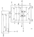
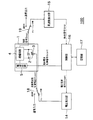
図1は、本発明の実施例1に係る電圧制御発振器の回路構成を示す図である。 1 is a diagram illustrating a circuit configuration of a voltage controlled oscillator according to a first embodiment of the present invention.
図1に示すように、電圧制御発振器1は、インダクタ2と可変容量素子3を含みこの可変容量素子3に供給される発振周波数制御電圧Vcontに応じた発振周波数の発振信号を出力する増幅回路4と、この増幅回路4に動作電流Iccを供給する電源回路5と、を備えている。
As shown in FIG. 1, the voltage controlled
インダクタ2は、可変容量素子3とともに共振器を構成する。
The
可変容量素子3は、例えば、可変容量ダイオード3aと可変容量ダイオード3bとを含む。この可変容量ダイオード3aのアノードは、インダクタ2の一端2aに接続されるとともに、可変容量ダイオード3aのカソードは、可変容量ダイオード3bのカソードに接続される。そして、この可変容量ダイオード3bのアノードは、インダクタ2の他端2bに接続されている。これらの可変容量ダイオード3a、3bの共通接続されたカソードに発振周波数制御電圧端子6から入力される既述の発振周波数制御電圧Vcontが供給される。
The
ここで、増幅回路4は、既述のインダクタ2と、可変容量素子3と、ソースが電源回路5の出力端子5aに接続され、ドレインがインダクタ2の一端2aに接続され、ゲートがインダクタ2の他端2bに接続された第1のp型MOSトランジスタ7と、ソースが第1のp型MOSトランジスタ7のソースに接続され、ゲートが第1のp型MOSトランジスタ7のドレインに接続され、ドレインが第1のp型MOSトランジスタ7のゲートに接続された第2のp型MOSトランジスタ8と、ソースが接地電位に接続され、ドレインがインダクタ2の一端2aに接続され、ゲートがインダクタ2の他端2bに接続された第1のn型MOSトランジスタ9と、ソースが第1のn型MOSトランジスタ9のソースに接続され、ゲートが第1のn型MOSトランジスタ9のドレインに接続され、ドレインが第1のn型MOSトランジスタ9のゲートに接続された第2のn型MOSトランジスタ10とを有する。
Here, the
この増幅回路4は、発振周波数制御電圧Vcontおよび動作電流Iccの入力に基づいて、発振信号Soscを出力端子4a、4bから出力する。
The
電源回路5は、ソースが電源電位Vddに接続され、ドレインが動作電流制御端子11に接続され、ゲートがドレインに接続された第3のp型MOSトランジスタ12と、ソースが第3のp型MOSトランジスタ12のソースに接続され、ドレインが電源回路5の出力端子5aに接続され、ゲートが第3のp型MOSトランジスタ12のゲートに接続された第4のp型MOSトランジスタ13とを有する。
The
これらの第3、第4のp型MOSトランジスタ12、13は、ミラー回路を構成し、動作電流制御端子11に入力された電流とカレントミラーとなる電流を出力端子5aから動作電流Iccとして出力する。
The third and fourth p-
ここで、既述のような構成を有する電圧制御発振器の発振周波数と発振周波数制御電圧との関係について説明する。 Here, the relationship between the oscillation frequency of the voltage controlled oscillator having the configuration as described above and the oscillation frequency control voltage will be described.
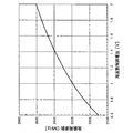
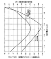
図2は、増幅回路の動作電流を固定した状態の電圧制御発振器の周波数制御特性を示す図である。 FIG. 2 is a diagram illustrating frequency control characteristics of the voltage controlled oscillator in a state where the operating current of the amplifier circuit is fixed.
図2に示すように、発振周波数制御電圧が上昇するのに対応して発振周波数が上昇しており、増幅回路の動作電流を固定した状態においては、測定された範囲では発振周波数が発振周波数制御電圧の単調増加関数となっている。このように、増幅回路の動作電流を固定した状態では、発振周波数制御電圧と発振周波数とは、一対一に対応している。 As shown in FIG. 2, when the oscillation frequency control voltage is increased, the oscillation frequency is increased. When the operating current of the amplifier circuit is fixed, the oscillation frequency is controlled within the measured range. It is a monotonically increasing function of voltage. Thus, in a state where the operating current of the amplifier circuit is fixed, the oscillation frequency control voltage and the oscillation frequency have a one-to-one correspondence.
このように図1の電圧制御発振器1は、発振周波数−発振周波数制御電圧特性が正の傾きを持つ。
As described above, the voltage controlled
なお、図1の可変容量ダイオード(pn接合型バリキャップ)3a、3bについて、容量−印加電圧特性が逆のバリキャップを使う、あるいは、可変容量ダイオード(pn接合型バリキャップ)3a、3bの接合の向きを逆にした場合は、図1の電圧制御発振器1は、発振周波数−発振周波数制御電圧特性が負の傾きを持つ。すなわち、発振周波数制御電圧が上昇するのに対応して発振周波数が下降し、増幅回路の動作電流を固定した状態においては、測定された範囲では発振周波数が発振周波数制御電圧の単調減少関数となる。
Note that the variable capacitance diodes (pn junction type varicaps) 3a and 3b in FIG. 1 use varicaps having opposite capacitance-applied voltage characteristics, or the junctions of the variable capacitance diodes (pn junction type varicaps) 3a and 3b. 1 is reversed, the voltage controlled
このように、周波数が上がったのを戻そうとするときに、発振周波数−発振周波数制御電圧特性が正の傾きの電圧制御発振器1の場合は制御電圧を下げる方向である(図2)が、発振周波数−発振周波数制御電圧特性が負の傾きの電圧制御発振器の場合は制御電圧を上げる方向になる。
As described above, when the frequency is increased, the control voltage is decreased in the case of the voltage controlled
次に、既述のような、インダクタと可変容量素子とを含み可変容量素子に供給される発振周波数制御電圧に応じた発振周波数の発振信号を出力する増幅回路と、この増幅回路に動作電流を供給する電源回路とを備える電圧制御発振器の動作電流と位相雑音の関係および動作電流と発振周波数の関係について説明する。 Next, an amplifier circuit that outputs an oscillation signal having an oscillation frequency corresponding to the oscillation frequency control voltage supplied to the variable capacitance element, including the inductor and the variable capacitance element, as described above, and operating current to the amplification circuit. The relationship between the operating current and the phase noise and the relationship between the operating current and the oscillation frequency of the voltage controlled oscillator including the power supply circuit to be supplied will be described.
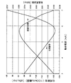
図3は、電圧制御発振器の動作電流と位相雑音の関係および動作電流と発振周波数の関係を示す図である。 FIG. 3 is a diagram showing the relationship between the operating current and the phase noise of the voltage controlled oscillator and the relationship between the operating current and the oscillation frequency.
ここで、従来、電圧制御発振器は制御電圧を入力として共振器の共振周波数を変化させ発振周波数を変化させるものである。しかし、制御電圧を固定した状態で、電圧制御発振器内の増幅回路に印加する電流を変化させると若干ではあるが発振周波数が変化する。このとき、位相雑音特性を同時に観測すると、両者の間には発振周波数が極大となった電流値において、位相雑音が最小となる関係がある。すなわち、発振周波数が極大となった電流値において、最も位相雑音特性が良好となる。 Here, conventionally, the voltage controlled oscillator changes the oscillation frequency by changing the resonance frequency of the resonator with the control voltage as an input. However, if the current applied to the amplifier circuit in the voltage controlled oscillator is changed with the control voltage fixed, the oscillation frequency changes slightly. At this time, when the phase noise characteristics are observed at the same time, there is a relationship between which the phase noise is minimized at the current value at which the oscillation frequency is maximized. That is, the phase noise characteristic is the best at the current value at which the oscillation frequency is maximized.
図3に示すように、動作電流の値が約5.7mAのとき、位相雑音が約-103dBc/Hzの最小値となる。したがって、この動作電流の値において最も位相雑音特性が良好となり最適である。 As shown in FIG. 3, when the value of the operating current is about 5.7 mA, the phase noise becomes the minimum value of about −103 dBc / Hz. Therefore, the phase noise characteristic is the best at the value of this operating current, which is optimal.
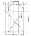
図4は、図3と製造条件の異なる電圧制御発振器の動作電流と位相雑音の関係および動作電流と発振周波数の関係を示す図である。 FIG. 4 is a diagram showing the relationship between the operating current and the phase noise and the relationship between the operating current and the oscillation frequency of the voltage controlled oscillator having different manufacturing conditions from FIG.
図4に示すように、位相雑音特性および発振周波数特性の傾向は図3と同様である。この場合の最適な電流値は約6.3mAとなり、図3の場合とは異なる。 As shown in FIG. 4, the tendency of the phase noise characteristic and the oscillation frequency characteristic is the same as in FIG. The optimum current value in this case is about 6.3 mA, which is different from the case of FIG.
このように、製造条件や制御電圧によって位相雑音特性が良好となる電流値は異なるが、発振周波数が極大となった電流値において位相雑音が最小となる変化の傾向は一定である。 As described above, although the current value at which the phase noise characteristic is good differs depending on the manufacturing conditions and the control voltage, the tendency of the change in which the phase noise is minimized at the current value at which the oscillation frequency is maximized is constant.
ここで、位相雑音特性の測定は大きな外部装置が必要となり、集積回路内で実現することは困難である。しかし、集積回路内部で発振周波数を測定するのは比較的容易に行うことができる。 Here, the measurement of the phase noise characteristic requires a large external device and is difficult to realize in the integrated circuit. However, it is relatively easy to measure the oscillation frequency inside the integrated circuit.
そこで、本実施例では、位相雑音を直接測定する代わりに、この電圧制御発振器の動作電流と位相雑音の関係を利用し、動作電流による発振周波数の変化を観測し、集積回路内で自動調整を行うものである。 Therefore, in this embodiment, instead of directly measuring the phase noise, the relationship between the operating current of the voltage controlled oscillator and the phase noise is used, the change in the oscillation frequency due to the operating current is observed, and the automatic adjustment is performed in the integrated circuit. Is what you do.
次に、上記電圧制御発振器の動作電流と位相雑音との関係を利用して発振信号の位相雑音特性を調整する動作電流調整装置の構成について説明する。 Next, the configuration of the operating current adjusting device that adjusts the phase noise characteristics of the oscillation signal using the relationship between the operating current of the voltage controlled oscillator and the phase noise will be described.
図5は、本発明の実施例1に係る動作電流調整装置の要部構成を示す図である。 FIG. 5 is a diagram illustrating a main configuration of the operating current adjusting apparatus according to the first embodiment of the present invention.
図5に示すように、動作電流調整装置100は、電圧制御発振器1と、発振周波数制御電圧を出力する電圧発生部14と、発振信号の発振周波数を測定する周波数検出部15と、電圧発生部14が発振周波数制御電圧Vcontを制御するための電圧設定信号Svsetを出力するとともに、周波数検出部15で測定された発振周波数に基づいて電源回路5が動作電流Iccを制御するための動作電流制御信号Scontを出力する制御部16と、を備えている。
As shown in FIG. 5, the operating
動作電流調整装置100は、制御部16で抽出された動作電流Iccを記憶する記憶部17を、さらに備える。
The operating
また、動作電流調整装置100は、通常使用モードである第1のモードと自動調整を行うトレーニングモードである第2のモードとを切り替えるスイッチ回路18、19を備えている。
In addition, the operating
ここで、第1のモードでは、スイッチ回路18、19が切り替えられて、PLL(Phase Locked Loop)回路等の外部回路に接続された通常入力、通常出力に電圧制御発振器1が接続される。なお、動作電流制御信号Scontは第2のモードで決定された値が制御部16から入力される。
Here, in the first mode, the
一方、第2のモードでは、スイッチ回路18、19が切り替えられて、電圧発生部14から出力された発振周波数制御電圧Vcontが電圧制御発振器1に入力され、電圧制御発振器1から出力された発振信号Soscが周波数検出部15に入力される。
On the other hand, in the second mode, the
電圧発生部14は、既述のように、制御部16から出力された電圧設定信号Svsetにより、決まった電圧を発生し電圧制御発振器に発振周波数制御電圧Vcontを供給する。
As described above, the
周波数検出部15は、電圧制御発振器1の発振信号Soscを受け取り発振周波数に変換し制御部16に発振周波数の情報を含む検出信号Sfdを出力する。この周波数検出部15は、例えば、発振周波数を測定するためのカウンタ等を内蔵している。
The frequency detector 15 receives the oscillation signal Sosc of the voltage controlled
制御部16は、第2のモードにおいて、電圧設定信号Svsetを電圧発生部14に出力して発振周波数制御電圧Vcontを所望の値に固定させる。さらに、制御部16は、動作電流制御信号Scontにより電源回路5から出力される動作電流Iccを変化させる。そして、制御部16は、周波数検出部15で測定された発振信号Soscの発振周波数が極大値近傍となる動作電流Iccの値を抽出する。そして、制御部16は、電源回路5から出力される動作電流Iccをこの抽出された動作電流Iccの値に設定するように動作電流制御信号Scontを出力する。
In the second mode, the
なお、この第2のモードは、第1のモードとの動作条件の差を小さくするために、できるだけ実使用状態に近い条件で行われるのが好ましい。 The second mode is preferably performed under conditions as close as possible to the actual use state in order to reduce the difference in operating conditions from the first mode.
また、所望の位相雑音特性を得るために、動作電流Iccは、第1のモードで使用する前に、第2のモードで自動調整される。 In order to obtain a desired phase noise characteristic, the operating current Icc is automatically adjusted in the second mode before being used in the first mode.
次に、以上のような構成・機能を有する動作電流調整装置100の動作、すなわち電圧制御発振器1の動作電流調整方法について、フローチャートに沿って以下説明する。ここでは、特に、動作電流調整装置100のスイッチ回路18、19が切り替えられてトレーニングする第2のモードにおける動作について説明する。
Next, the operation of the operating
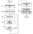
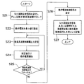
図6は、本発明の実施例1に係る動作電流調整装置の電圧制御発振器の発振信号を調整する動作例を示すフローチャートである。 FIG. 6 is a flowchart illustrating an operation example of adjusting the oscillation signal of the voltage controlled oscillator of the operating current adjusting device according to the first embodiment of the present invention.
図6に示すように、先ず、制御部16は、電圧設定信号Svsetを電圧発生部14に出力し、発振周波数制御電圧Vcontを設定する(ステップS1)。この発振周波数制御電圧Vcontは、通常使用モードである第1のモードで実際に使用する電圧値と同一であることが望ましい。
As shown in FIG. 6, first, the
次に、制御部16は、所望の動作電流制御信号Scontを出力して、電源回路5から出力される動作電流Iccを十分小さい値に設定する(ステップS2)。ここでは、電圧制御発振器の発振出力が継続可能な下限の電流まで小さくしてもよい。
Next, the
次に、制御部16は、周波数検出部15により検出された発振周波数を記憶部17に記憶する(ステップS3)。
Next, the
次に、制御部16は、動作電流制御信号Scontを変化させて、電源回路5から出力される動作電流Iccを所定値だけ増加させる(ステップS4)。
Next, the
次に、制御部16は、ステップS4の動作電流Iccで、周波数検出部15により検出された発振周波数を、ステップS3で記憶された発振周波数と比較する。周波数検出部15により検出された発振周波数が、ステップS3で記憶された発振周波数よりも、増加している場合はステップS3に戻りこの増加した発振周波数を記憶する(ステップS5)。
Next, the
一方、ステップS5において、周波数検出部15により検出された発振周波数が、ステップS3で記憶された発振周波数よりも減少している場合は、制御部16は、この発振周波数が極大値近傍であると判断し、次のステップに進む。
On the other hand, when the oscillation frequency detected by the frequency detection unit 15 is smaller than the oscillation frequency stored in step S3 in step S5, the
以上のステップS1ないしS5により、発振周波数制御電圧Vcontを所望の値に固定した状態で電源回路5から出力される動作電流を変化させる。
Through the above steps S1 to S5, the operating current output from the
ここで、ステップS4の動作電流Iccは、発振周波数が極大となる電流値を越えているので、該所定値だけ減少させた動作電流Iccを位相雑音特性が最適となるものとして設定する(ステップS6)。このとき、通常、動作電流Iccは電流最適値の低い側が安定した位相雑音特性が得られることから、該所望値よりも大きい値だけ減少させてもよい。また、電圧制御発振器1の要求される精度によっては、ステップS4で出力された動作電流Iccを位相雑音特性が最適となるものとして設定してもよい。
Here, since the operating current Icc in step S4 exceeds the current value at which the oscillation frequency is maximized, the operating current Icc reduced by the predetermined value is set so that the phase noise characteristic is optimal (step S6). ). At this time, normally, the operating current Icc may be decreased by a value larger than the desired value because a stable phase noise characteristic can be obtained on the lower current optimum value side. Further, depending on the required accuracy of the voltage controlled
次に、制御部16は、設定された発振周波数制御電圧値Vcontあるいは測定された発振周波数と動作電流制御信号Scontとを対にして記憶部17に記憶する(ステップS7)。
Next, the
以上のステップS6、S7により、発振信号の発振周波数が極大値近傍となる動作電流の値を抽出し、この動作電流の値を増幅回路から出力される動作電流の値に設定する。 Through the above steps S6 and S7, the value of the operating current at which the oscillation frequency of the oscillation signal is near the maximum value is extracted, and the value of the operating current is set to the value of the operating current output from the amplifier circuit.
以上のフローにより、動作電流調整装置100の電圧制御発振器1の発振信号を調整するための動作が完了する。
With the above flow, the operation for adjusting the oscillation signal of the voltage controlled
なお、電圧制御発振器1に入力される発振周波数制御電圧Vcontが複数設定される場合には、ステップS1に戻り、再度異なる発振周波数制御電圧Vcontで上記フローが実施される。制御部16は、通常動作である第1のモードでは、記憶部17に記憶された動作電流制御信号Scontの中から発振周波数制御電圧Vcontあるいは発振周波数に対応する適切な値を読み込み、電圧制御発振器1に動作電流制御信号Scontを出力する。
When a plurality of oscillation frequency control voltages Vcont input to the voltage controlled
これにより、電圧制御発振器1は、通常動作である第1のモードにおいて、位相雑音特性が安定した、発振信号を出力することができる。
Thereby, the voltage controlled
ここで、上述のフローチャートにおいては、動作電流Iccを小さい値(最小値)から増加させて発振周波数の極大値近傍の動作電流Iccを求めているが、動作電流Iccを大きい値(最大値)から減少させて発振周波数の極大値近傍の動作電流Iccを求めてもよい。 Here, in the above flowchart, the operating current Icc is increased from a small value (minimum value) to obtain the operating current Icc near the maximum value of the oscillation frequency, but the operating current Icc is determined from a large value (maximum value). The operating current Icc near the maximum value of the oscillation frequency may be obtained by decreasing the value.
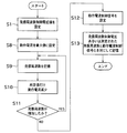
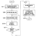
図7は、本発明の実施例1に係る動作電流調整装置の電圧制御発振器の発振信号を調整する他の動作例を示すフローチャートである。 FIG. 7 is a flowchart showing another operation example of adjusting the oscillation signal of the voltage controlled oscillator of the operating current adjusting device according to the first embodiment of the present invention.
図7に示すように、先ず、制御部16は、電圧設定信号Svsetを電圧発生部14に出力し、発振周波数制御電圧Vcontを設定する(ステップS1)。この発振周波数制御電圧Vcontは、通常使用モードである第1のモードで実際に使用する電圧値と同一であることが望ましい。
As shown in FIG. 7, first, the
次に、制御部16は、所望の動作電流制御信号Scontを出力して、電源回路5から出力される動作電流Iccを十分大きい値(最大値)に設定する(ステップS8)。なお、例えば、発振周波数が極大となる動作電流Iccの概略値が認識されている場合は、この値よりも所定値以上大きい値に設定すればよい。
Next, the
次に、制御部16は、周波数検出部15により検出された発振周波数を記憶部17に記憶する(ステップS9)。
Next, the
次に、制御部16は、動作電流制御信号Scontを変化させて、電源回路5から出力される動作電流Iccを該所定値だけ減少させる(ステップS10)。
Next, the
次に、制御部16は、ステップS10の動作電流Iccで、周波数検出部15により検出された発振周波数を、ステップS9で記憶された発振周波数と比較する。周波数検出部15により検出された発振周波数が、ステップS9で記憶された発振周波数よりも増加している場合はステップS9に戻りこの増加した発振周波数を記憶する(ステップ11)。
Next, the
一方、ステップS11において、周波数検出部15により検出された発振周波数が、ステップS9で記憶された発振周波数よりも減少している場合は、制御部16は、この発振周波数が極大値近傍であると判断し、次のステップに進む。
On the other hand, when the oscillation frequency detected by the frequency detection unit 15 is smaller than the oscillation frequency stored in step S9 in step S11, the
以上のステップS1ないしS11により、発振周波数制御電圧Vcontを所望の値に固定した状態で電源回路5から出力される動作電流を変化させる。
Through the above steps S1 to S11, the operating current output from the
ここで、ステップS10の動作電流Iccは、発振周波数が極大となる電流値よりも小さいので、該所定値だけ増加させ、この増加させた動作電流Iccを位相雑音特性が最適となるものとして設定する(ステップS12)。このとき、通常、動作電流Iccは電流最適値の低い側が安定した位相雑音特性が得られることから、該所定値だけ増加させずに、ステップS11で出力された動作電流Iccを位相雑音特性が最適となるものとして設定してもよい。 Here, since the operating current Icc in step S10 is smaller than the current value at which the oscillation frequency is maximized, the operating current Icc is increased by the predetermined value, and the increased operating current Icc is set so that the phase noise characteristic is optimal. (Step S12). At this time, since the operating current Icc usually has a stable phase noise characteristic at the lower current optimum value, the phase noise characteristic of the operating current Icc output in step S11 is optimal without increasing the predetermined value. It may be set as
次に、制御部16は、設定された発振周波数制御電圧値Vcontあるいは測定された発振周波数と動作電流制御信号Scontとを対にして記憶部17に記憶する(ステップS13)。
Next, the
以上のステップS12、S13により、発振信号の発振周波数が極大値近傍となる動作電流の値を抽出し、この動作電流の値を増幅回路から出力される動作電流の値に設定する。 Through the above steps S12 and S13, the value of the operating current at which the oscillation frequency of the oscillation signal is close to the maximum value is extracted, and the value of the operating current is set to the value of the operating current output from the amplifier circuit.
以上のフローにより、動作電流調整装置100の電圧制御発振器1の動作電流を調整するための動作が完了する。
With the above flow, the operation for adjusting the operating current of the voltage controlled
なお、図6、図7のフローチャートに示す動作電流調整装置の動作電流調整方法以外にも、一度、掃引可能な動作電流Iccに対して発振周波数の特性を測定した後、計算により発振周波数の極大値近傍の動作電流Iccを求める方法等が考えられる。 In addition to the operating current adjusting method of the operating current adjusting device shown in the flowcharts of FIGS. 6 and 7, once the oscillation frequency characteristic is measured for the sweepable operating current Icc, the oscillation frequency is maximized by calculation. A method for obtaining the operating current Icc near the value can be considered.
以上のように、本実施例に係る動作電流調整装置によれば、発振周波数制御電圧を所望の値に固定した状態で電源回路から出力される動作電流を変化させ、発振信号の発振周波数が極大値近傍となる動作電流の値を抽出し、この動作電流の値を増幅回路から出力される動作電流の値に設定するので、電圧制御発振器の位相雑音特性を自動的に調整することができる。 As described above, according to the operating current adjusting device according to the present embodiment, the operating current output from the power supply circuit is changed in a state where the oscillation frequency control voltage is fixed to a desired value, and the oscillation frequency of the oscillation signal is maximized. Since the value of the operating current in the vicinity of the value is extracted and this operating current value is set to the value of the operating current output from the amplifier circuit, the phase noise characteristic of the voltage controlled oscillator can be automatically adjusted.
なお、本実施例においては、増幅回路4、電源回路5を構成するトランジスタがMOSトランジスタである場合について説明したが、MOSトランジスタの導電型を逆にした場合についても、各回路構成の極性を逆にすることにより同様に適用できる。
In this embodiment, the transistors constituting the
また、本実施例においては、増幅回路4、電源回路5を構成するトランジスタがMOSトランジスタである場合について説明したが、各回路構成において、バイポーラトランジスタを代替的に用いることもできる。
In the present embodiment, the case where the transistors constituting the
実施例1では、例えば、電圧制御発振器がPLL回路等の外部回路に含まれない構成について述べたが、本実施例では、電圧制御発振器がPLL回路に含まれた構成について述べる。 In the first embodiment, for example, the configuration in which the voltage controlled oscillator is not included in the external circuit such as the PLL circuit has been described, but in the present embodiment, the configuration in which the voltage controlled oscillator is included in the PLL circuit will be described.
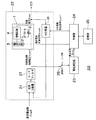
図8は、本発明の一態様である実施例2に係る動作電流調整装置200の要部の構成を示す断面図である。なお、図中、実施例1と同じ符号は、実施例1と同様の構成を示している。
FIG. 8: is sectional drawing which shows the structure of the principal part of the operating
図8に示すように、動作電流調整装置200は、インダクタ2と可変容量素子3とを含みこの可変容量素子3に供給される発振周波数制御電圧Vcontに応じた周波数の発振信号Soscを出力する増幅回路4、この増幅回路4に動作電流Iccを供給する電源回路5とを含む電圧制御発振器1、発振信号SoscをN分の1に分周し信号を出力するN分周器20、および、このN分周器20の出力信号の発振周波数と基準周波数Frefとを比較し位相差信号を生成する位相比較器21、この位相比較器21が出力する位相差信号に基づいて発振周波数制御電圧Vcontを出力するループフィルタ27を有するPLL回路22を備える。
As shown in FIG. 8, the operating
さらに、動作電流調整装置200は、発振周波数制御電圧Vcontを測定する電圧測定部23と、この電圧測定部23で測定された発振周波数制御電圧Vcontに基づいて電源回路5が動作電流Iccを制御するための動作電流制御信号Scontを出力する制御部24とを備える。
Further, in the operating
また、動作電流調整装置200は、抽出された動作電流Iccを記憶する記憶部25をさらに備える。
The operating
N分周器20は、制御部24から入力されるN分周設定信号Sdsetにより制御され、既述のように発振信号SoscをN分の1に分周し信号を出力する。
The
位相比較器21は、出力信号の発振周波数と基準周波数Frefとの位相比較を行ない、位相差をパルス状の位相差信号として生成する。
The
ループフィルタ27は、位相比較器21が出力した位相差信号から交流成分を取り除いて発振周波数制御電圧Vcontを生成し、電圧制御発振器1に入力する。
The
制御部24は、動作電流制御信号Scontにより電源回路5から出力される動作電流Iccを変化させ、電圧測定部23で測定された発振周波数制御電圧Vcontの値が極小値近傍となる動作電流Iccの値を抽出し、電源回路5から出力される動作電流Iccをこの抽出された動作電流Iccの値に設定するように動作電流制御信号Scontを出力する。
The
なお、ここでは上記のように、図1の電圧制御発振器の発振周波数−発振周波数制御電圧特性が正の傾きの場合(図2に示す)は極小値近傍となる動作電流Iccの値を抽出している。一方、電圧制御発振器の発振周波数−発振周波数制御電圧特性が負の傾きをとる場合は極大値近傍となる動作電流Iccの値を抽出する。以下、同様である。 Here, as described above, when the oscillation frequency-oscillation frequency control voltage characteristic of the voltage controlled oscillator of FIG. 1 has a positive slope (shown in FIG. 2), the value of the operating current Icc near the minimum value is extracted. ing. On the other hand, when the oscillation frequency-oscillation frequency control voltage characteristic of the voltage controlled oscillator has a negative slope, the value of the operating current Icc near the maximum value is extracted. The same applies hereinafter.
また、動作電流調整装置200は、通常使用モードである第1のモードと自動調整を行うトレーニングモードである第2のモードとを切り替えるスイッチ回路26を備えている。
In addition, the operating
ここで、第1のモードでは、スイッチ回路26が切り替えられて開放され、発振周波数制御電圧Vcontが電圧測定部23に入力されない。そして、既述のように、電圧制御発振器1の制御電圧入力はループフィルタ27の出力に接続され、電圧制御発振器1の発振信号Soscは、N分周器20や外部回路(図示せず)に接続されており、通常のPLL動作を行う。なお、動作電流制御信号Scontは第2のモードで決定された値が制御部24から入力される。
Here, in the first mode, the
一方、第2のモードでは、スイッチ回路26が切り替えられて、ループフィルタ27から出力された発振周波数制御電圧Vcontが電圧測定部23に入力され、この電圧測定部23で測定された電圧値に応じた検出信号Svdが電圧測定部23から制御部24に入力される。
On the other hand, in the second mode, the
なお、この第2のモードは、第1のモードとの動作条件の差を小さくするために、できるだけ実使用状態に近い条件で行われるのが好ましい。 The second mode is preferably performed under conditions as close as possible to the actual use state in order to reduce the difference in operating conditions from the first mode.
また、所望の位相雑音特性を得るために、動作電流Iccは、第1のモードで使用する前に、第2のモードで自動調整される。 In order to obtain a desired phase noise characteristic, the operating current Icc is automatically adjusted in the second mode before being used in the first mode.
ここで、既述のようなPLL回路に含まれた、インダクタと可変容量素子とを含み可変容量素子に供給される発振周波数制御電圧に応じた発振周波数の発振信号を出力する増幅回路と、この増幅回路に動作電流を供給する電源回路とを備える電圧制御発振器の動作電流と位相雑音の関係および動作電流と発振周波数制御電圧の関係について説明する。 Here, an amplifier circuit included in the PLL circuit as described above, which includes an inductor and a variable capacitance element, outputs an oscillation signal having an oscillation frequency corresponding to an oscillation frequency control voltage supplied to the variable capacitance element, and this The relationship between the operating current and the phase noise of the voltage controlled oscillator including the power supply circuit that supplies the operating current to the amplifier circuit and the relationship between the operating current and the oscillation frequency control voltage will be described.
図9は、電圧制御発振器の動作電流と位相雑音の関係および動作電流と発振周波数制御電圧の関係を示す図である。なお、PLL回路22において発振信号Soscの周波数を2400MHzに固定している。
FIG. 9 is a diagram showing the relationship between the operating current and the phase noise of the voltage controlled oscillator and the relationship between the operating current and the oscillation frequency control voltage. In the
ここで、周波数を固定した状態で、電圧制御発振器1内の増幅回路4に印加する電流を変化させると若干ではあるが発振周波数制御電圧Vcontが変化する。このとき、位相雑音特性を同時に観測すると、両者の間には発振周波数制御電圧Vcontが極小となった電流値において、位相雑音が最小となる関係がある。すなわち、発振周波数制御電圧Vcontが極小となった電流値において、最も位相雑音特性が良好となる。
Here, if the current applied to the
図9に示すように、動作電流の値が約5.2mAのとき、位相雑音が約-103dBc/Hzの最小値となる。したがって、この動作電流の値において最も位相雑音特性が良好となり最適である。 As shown in FIG. 9, when the value of the operating current is about 5.2 mA, the phase noise becomes the minimum value of about −103 dBc / Hz. Therefore, the phase noise characteristic is the best at the value of this operating current, which is optimal.
そこで、本実施例では、位相雑音を直接測定する代わりに、この電圧制御発振器の動作電流と位相雑音の関係を利用し、動作電流による発振周波数制御電圧Vcontの変化を観測し、集積回路内で自動調整を行うものである。 Therefore, in this embodiment, instead of directly measuring the phase noise, the relationship between the operating current of the voltage controlled oscillator and the phase noise is used, and the change of the oscillation frequency control voltage Vcont due to the operating current is observed. Automatic adjustment is performed.
次に、以上のような構成・機能を有する動作電流調整装置200の動作、すなわち電圧制御発振器1の動作電流調整方法について、フローチャートに沿って以下説明する。ここでは、特に、動作電流調整装置200のスイッチ回路26が切り替えられてトレーニングする第2のモードにおける動作について説明する。
Next, the operation of the operating
図10は、本発明の実施例2に係る動作電流調整装置の電圧制御発振器の発振信号を調整する動作例を示すフローチャートである。 FIG. 10 is a flowchart illustrating an operation example of adjusting the oscillation signal of the voltage controlled oscillator of the operating current adjusting device according to the second embodiment of the present invention.
図10に示すように、先ず、制御部24は、N分周設定信号SdsetをN分周器20に出力し、第1のモードで使用する発振周波数にPLL回路22をロックする。(ステップS21)。
As shown in FIG. 10, first, the
次に、制御部24は、所望の動作電流制御信号Scontを出力して、電源回路5から出力される動作電流Iccを十分小さい値に設定する(ステップS22)。ここでは、電圧制御発振器の発振出力が継続可能な下限の電流まで小さくしてもよい。
Next, the
次に、制御部24は、電圧測定部23により測定された発振周波数制御電圧Vcontを記憶部25に記憶する(ステップS23)。
Next, the
次に、制御部24は、動作電流制御信号Scontを変化させて、電源回路5から出力される動作電流Iccを所定値だけ増加させる(ステップS24)。
Next, the
次に、制御部24は、ステップS24の動作電流Iccで、電圧測定部23により測定された発振周波数制御電圧Vcontを、ステップS23で記憶された発振周波数制御電圧Vcontと比較する。電圧測定部23により測定された発振周波数制御電圧Vcontが、ステップS23で記憶された発振周波数制御電圧Vcontよりも、下がっている場合はステップS23に戻りこの下がった発振周波数制御電圧Vcontを記憶する(ステップS25)。
Next, the
一方、ステップS25において、電圧測定部23により測定された発振周波数制御電圧Vcontが、ステップS23で記憶された発振周波数制御電圧Vcontよりも上がっている場合は、制御部24は、この発振周波数制御電圧Vcontが極小値近傍であると判断し、次のステップに進む。
On the other hand, when the oscillation frequency control voltage Vcont measured by the
以上のステップS21ないしS25により、発振周波数を所望の値に固定した状態で電源回路5から出力される動作電流を変化させる。
Through the above steps S21 to S25, the operating current output from the
ここで、ステップS4の動作電流Iccは、発振周波数制御電圧Vcontが極大となる電流値を越えているので、該所定値だけ減少させた動作電流Iccを位相雑音特性が最適となるものとして設定する(ステップS26)。このとき、通常、動作電流Iccは電流最適値の低い側が安定した位相雑音特性が得られることから、該所望値よりも大きい値だけ減少させてもよい。また、電圧制御発振器1の要求される精度によっては、ステップS24で出力された動作電流Iccを位相雑音特性が最適となるものとして設定してもよい。
Here, since the operating current Icc in step S4 exceeds the current value at which the oscillation frequency control voltage Vcont becomes a maximum, the operating current Icc reduced by the predetermined value is set so that the phase noise characteristic is optimal. (Step S26). At this time, normally, the operating current Icc may be decreased by a value larger than the desired value because a stable phase noise characteristic can be obtained on the lower current optimum value side. Further, depending on the accuracy required of the voltage controlled
次に、制御部24は、N分周設定信号Sdsetあるいは期待される発振周波数と設定された動作電流制御信号Scontとを対にして記憶部25に記憶する(ステップS27)。
Next, the
以上のステップS26、S27により、発振信号の発振周波数が極大値近傍となる動作電流の値を抽出し、この動作電流の値を増幅回路から出力される動作電流の値に設定する。 Through the above steps S26 and S27, the value of the operating current at which the oscillation frequency of the oscillation signal is in the vicinity of the maximum value is extracted, and this operating current value is set to the value of the operating current output from the amplifier circuit.
以上のフローにより、動作電流調整装置200の電圧制御発振器1の動作電流を調整するための動作が完了する。
With the above flow, the operation for adjusting the operating current of the voltage controlled
なお、PLL回路22の発振周波数が複数設定される場合には、ステップS21に戻り、再度異なる発振周波数で上記フローが実施される。制御部24は、通常動作である第1のモードでは、記憶部25に記憶されたN分周設定信号Sdsetあるいは発振周波数と設定された動作電流制御信号Scontとの中から発振周波数に対応する適切な値を読み込み、電圧制御発振器1に動作電流制御信号Scontを出力しN分周器20にN分周設定信号Sdsetを出力する。
When a plurality of oscillation frequencies of the
これにより、電圧制御発振器1は、通常動作である第1のモードにおいて、位相雑音特性が安定した、発振信号を出力することができる。
Thereby, the voltage controlled
ここで、上述のフローチャートにおいては、動作電流Iccを小さい値(最小値)から増加させて発振周波数制御電圧Vcontの極小値近傍の動作電流Iccを求めているが、動作電流Iccを大きい値(最大値)から減少させて発振周波数制御電圧Vcontの極小値近傍の動作電流Iccを求めてもよい。 Here, in the above flowchart, the operating current Icc is increased from a small value (minimum value) to obtain the operating current Icc in the vicinity of the minimum value of the oscillation frequency control voltage Vcont. The operating current Icc in the vicinity of the minimum value of the oscillation frequency control voltage Vcont may be obtained by decreasing from the value.
図11は、本発明の実施例2に係る動作電流調整装置の電圧制御発振器の発振信号を調整する他の動作例を示すフローチャートである。 FIG. 11 is a flowchart showing another operation example of adjusting the oscillation signal of the voltage controlled oscillator of the operating current adjusting device according to the second embodiment of the present invention.
図11に示すように、先ず、制御部24は、N分周設定信号SdsetをN分周器20に出力し、第1のモードで使用する発振周波数にPLL回路22をロックする。(ステップS21)。
As shown in FIG. 11, first, the
次に、制御部24は、所望の動作電流制御信号Scontを出力して、電源回路5から出力される動作電流Iccを十分大きい値(最大値)に設定する(ステップS28)。なお、例えば、発振周波数制御電圧Vcontが極小となる動作電流Iccの概略値が認識されている場合は、この値よりも所定値以上大きい値に設定すればよい。
Next, the
次に、制御部24は、電圧測定部23により測定された発振周波数制御電圧Vcontを記憶部25に記憶する(ステップS29)。
Next, the
次に、制御部24は、動作電流制御信号Scontを変化させて、電源回路5から出力される動作電流Iccを所定値だけ減少させる(ステップS210)。
Next, the
次に、制御部24は、ステップS210の動作電流Iccで、電圧測定部23により測定された発振周波数制御電圧Vcontを、ステップS29で記憶された発振周波数制御電圧Vcontと比較する。電圧測定部23により測定された発振周波数制御電圧Vcontが、ステップS29で記憶された発振周波数制御電圧Vcontよりも、下がっている場合はステップS29に戻りこの下がった発振周波数制御電圧Vcontを記憶する(ステップ211)。
Next, the
一方、ステップS211において、電圧測定部23により測定された発振周波数制御電圧Vcontが、ステップS29で記憶された発振周波数制御電圧Vcontよりも上がっている場合は、制御部24は、この発振周波数制御電圧Vcontが極小値近傍であると判断し、次のステップに進む。
On the other hand, when the oscillation frequency control voltage Vcont measured by the
以上のステップS21ないしS211により、発振周波数を所望の値に固定した状態で電源回路5から出力される動作電流を変化させる。
Through the above steps S21 to S211, the operating current output from the
ここで、ステップS210の動作電流Iccは、発振周波数制御電圧Vcontが極小となる電流値よりも小さいので、該所定値だけ増加させ、この増加させた動作電流Iccを位相雑音特性が最適となるものとして設定する(ステップS12)。このとき、通常、動作電流Iccは電流最適値の低い側が安定した位相雑音特性が得られることから、該所定値だけ増加させずに、ステップS211で出力された動作電流Iccを位相雑音特性が最適となるものとして設定してもよい。 Here, since the operating current Icc in step S210 is smaller than the current value at which the oscillation frequency control voltage Vcont is minimized, the operating current Icc is increased by the predetermined value, and the increased operating current Icc is optimized in phase noise characteristics. (Step S12). At this time, since the operating current Icc usually has a stable phase noise characteristic on the side where the optimum current value is low, the operating current Icc output in step S211 is not optimally increased and the phase noise characteristic is optimal. It may be set as
次に、制御部24は、設定されたN分周設定信号Sdsetあるいは期待される発振周波数と動作電流制御信号Scontとを対にして記憶部25に記憶する(ステップS213)。
Next, the
以上のステップS212、S213により、発振周波数制御電圧Vcontが極小値近傍となる動作電流の値を抽出し、この動作電流の値を増幅回路から出力される動作電流の値に設定する。 Through the above steps S212 and S213, the operating current value at which the oscillation frequency control voltage Vcont is near the minimum value is extracted, and this operating current value is set to the operating current value output from the amplifier circuit.
以上のフローにより、動作電流調整装置200の電圧制御発振器1の動作電流を調整するための動作が完了する。
With the above flow, the operation for adjusting the operating current of the voltage controlled
なお、PLL回路22の発振周波数が複数設定される場合には、ステップS21に戻り、再度異なる発振周波数で上記フローが実施される。制御部24は、通常動作である第1のモードでは、記憶部25に記憶されたN分周設定信号Sdsetあるいは発振周波数と設定された動作電流制御信号Scontとの中から発振周波数に対応する適切な値を読み込み、電圧制御発振器1に動作電流制御信号Scontを出力しN分周器20にN分周設定信号Sdsetを出力する。
When a plurality of oscillation frequencies of the
これにより、電圧制御発振器1は、通常動作である第1のモードにおいて、位相雑音特性が安定した、発振信号を出力することができる。
Thereby, the voltage controlled
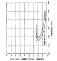
ここで、図12に、実施例1に係る電圧制御発振器の発振周波数と位相雑音の関係を示す。図12に示すように、製造条件が異なっても、良好な位相雑音特性が得られているのがわかる。 FIG. 12 shows the relationship between the oscillation frequency and the phase noise of the voltage controlled oscillator according to the first embodiment. As shown in FIG. 12, it can be seen that good phase noise characteristics are obtained even when the manufacturing conditions are different.
なお、図10、図11のフローチャートに示す動作電流調整装置の動作電流調整方法以外にも、一度、掃引可能な動作電流Iccに対して発振周波数の特性を測定した後、計算により発振周波数制御電圧Vcontの極小値近傍の動作電流Iccを求める方法等が考えられる。 In addition to the operating current adjusting method of the operating current adjusting device shown in the flowcharts of FIGS. 10 and 11, once the oscillation frequency characteristics are measured for the sweepable operating current Icc, the oscillation frequency control voltage is calculated. A method for obtaining the operating current Icc near the minimum value of Vcont can be considered.
以上のように、本実施例に係る動作電流調整装置によれば、発振周波数を所望の値に固定した状態で電源回路から出力される動作電流を変化させ、発振周波数制御電圧が極小値近傍となる動作電流の値を抽出し、この動作電流の値を増幅回路から出力される動作電流の値に設定するので、電圧制御発振器の位相雑音特性を自動的に調整することができる。 As described above, according to the operating current adjusting device according to the present embodiment, the operating current output from the power supply circuit is changed in a state where the oscillation frequency is fixed to a desired value, and the oscillation frequency control voltage is near the minimum value. The operating current value is extracted and the operating current value is set to the operating current value output from the amplifier circuit, so that the phase noise characteristic of the voltage controlled oscillator can be automatically adjusted.
なお、以上各実施例においては、第2のモードを、動作電流調整装置の電源の投入後に、使用周波数の一部または全部において繰り返し行うことにより、より効率的に実施することができる。 In each of the above embodiments, the second mode can be more efficiently implemented by repeatedly performing the second mode at part or all of the operating frequency after the operating current adjusting device is turned on.
また、以上各実施例においては、第2のモードを、使用する周波数が定まった後に、使用周波数の一部または全部において繰り返し行うことにより、より効率的に実施することができる。 In each of the embodiments described above, the second mode can be more efficiently implemented by repeatedly performing the second mode at a part or all of the used frequency after the frequency to be used is determined.
1 電圧制御発振器
2 インダクタ
3 可変容量素子
3a 可変容量ダイオード
3b 可変容量ダイオード
4 増幅回路
4a 出力端子
4b 出力端子
5 電源回路
5a 出力端子
5b 出力端子
6 発振周波数制御電圧端子
7 第1のp型MOSトランジスタ
8 第2のp型MOSトランジスタ
9 第1のn型MOSトランジスタ
10 第2のn型MOSトランジスタ
11 動作電流制御端子
12 第3のp型MOSトランジスタ
13 第4のp型MOSトランジスタ
14 電圧発生部
15 周波数検出部
16 制御部
17 記憶部
18 スイッチ回路
19 スイッチ回路
20 位相比較器
21 N分周器
22 PLL回路
23 電圧測定部
24 制御部
25 記憶部
26 スイッチ回路
27 ループフィルタ
100、200 動作電流調整装置
DESCRIPTION OF
Claims (5)
前記増幅回路に動作電流を供給する電源回路と、を備え、
発振周波数制御電圧を所望の値に固定した状態で前記電源回路から出力される前記動作電流を変化させ、前記発振信号の発振周波数が極大値近傍となる前記動作電流の値を抽出し、この抽出された動作電流の値を前記電源回路から出力される前記動作電流の値に設定する
ことを特徴とする電圧制御発振器。 An amplifier circuit that includes an inductor and a variable capacitance element and outputs an oscillation signal having an oscillation frequency corresponding to an oscillation frequency control voltage supplied to the variable capacitance element;
A power supply circuit for supplying an operating current to the amplifier circuit,
The operating current output from the power supply circuit is changed with the oscillation frequency control voltage fixed at a desired value, and the value of the operating current at which the oscillation frequency of the oscillation signal is close to the maximum value is extracted. A voltage-controlled oscillator, wherein the value of the operating current thus set is set to the value of the operating current output from the power supply circuit.
前記発振周波数制御電圧を出力する電圧発生部と、
前記発振信号の発振周波数を測定する周波数検出部と、
前記電圧発生部が発振周波数制御電圧を制御するための電圧設定信号を出力するとともに、前記周波数検出部で測定された発振周波数に基づいて前記電源回路が動作電流を制御するための動作電流制御信号を出力する制御部と、を備え、
前記制御部は、前記電圧設定信号を前記電圧発生部に出力して発振周波数制御電圧を所望の値に固定させるとともに前記動作電流制御信号により前記電源回路から出力される前記動作電流を変化させ、前記周波数検出部で測定された前記発振信号の発振周波数が極大値近傍となる前記動作電流の値を抽出し、前記電源回路から出力される前記動作電流をこの抽出された動作電流の値に設定するように前記動作電流制御信号を出力する
ことを特徴とする動作電流調整装置。 A voltage-controlled oscillator including an inductor and a variable capacitance element, an amplifier circuit that outputs an oscillation signal having a frequency corresponding to an oscillation frequency control voltage supplied to the variable capacitance element, and a power supply circuit that supplies an operating current to the amplification circuit When,
A voltage generator for outputting the oscillation frequency control voltage;
A frequency detector for measuring the oscillation frequency of the oscillation signal;
The voltage generator outputs a voltage setting signal for controlling the oscillation frequency control voltage, and the operating current control signal for the power supply circuit to control the operating current based on the oscillation frequency measured by the frequency detector And a control unit for outputting
The control unit outputs the voltage setting signal to the voltage generation unit to fix the oscillation frequency control voltage to a desired value and change the operating current output from the power supply circuit by the operating current control signal, The value of the operating current at which the oscillation frequency of the oscillation signal measured by the frequency detection unit is near the maximum value is extracted, and the operating current output from the power supply circuit is set to the value of the extracted operating current. The operating current control device outputs the operating current control signal.
前記発振周波数制御電圧を測定する電圧測定部と、
前記N分周器を制御するためのN分周設定信号を出力するとともに、前記電圧測定部で測定された発振周波数制御電圧に基づいて前記電源回路が動作電流を制御するための動作電流制御信号を出力する制御部と、を備え、
前記制御部は、前記N分周設定信号を前記N分周器に出力し発振周波数を所望の値に固定させるとともに前記動作電流制御信号により前記電源回路から出力される前記動作電流を変化させ、前記電圧測定部で測定された前記発振周波数制御電圧の値が、発振周波数−発振周波数制御電圧特性が正の傾きを持つ電圧制御発振器の場合は極小値近傍、または発振周波数−発振周波数制御電圧特性が負の傾きを持つ電圧制御発振器の場合は極大値近傍、となる前記動作電流の値を抽出し、前記電源回路から出力される前記動作電流をこの抽出された動作電流の値に設定するように前記動作電流制御信号を出力する
ことを特徴とする動作電流調整装置。 A voltage-controlled oscillator that includes an inductor and a variable capacitance element and outputs an oscillation signal having a frequency corresponding to an oscillation frequency control voltage supplied to the variable capacitance element, and a power supply circuit that supplies an operating current to the amplification circuit An N divider that outputs a signal obtained by dividing the oscillation signal by 1 / N, and a phase comparison that generates a phase difference signal by comparing the oscillation frequency of the output signal of the N divider with a reference frequency A PLL circuit having a loop filter that outputs the oscillation frequency control voltage based on a phase difference signal output from the phase comparator;
A voltage measuring unit for measuring the oscillation frequency control voltage;
An N current setting signal for controlling the N frequency divider, and an operating current control signal for controlling the operating current by the power supply circuit based on the oscillation frequency control voltage measured by the voltage measuring unit. And a control unit for outputting
The control unit outputs the N divider setting signal to the N divider and fixes the oscillation frequency to a desired value and changes the operating current output from the power supply circuit by the operating current control signal, The value of the oscillation frequency control voltage measured by the voltage measuring unit is a minimum value in the case of a voltage controlled oscillator having a positive slope of the oscillation frequency-oscillation frequency control voltage characteristic, or the oscillation frequency-oscillation frequency control voltage characteristic. In the case of a voltage controlled oscillator having a negative slope, the value of the operating current that is close to the maximum value is extracted, and the operating current output from the power supply circuit is set to the value of the extracted operating current. The operating current control signal is output to the operating current adjusting device.
発振周波数制御電圧を所望の値に固定した状態で前記電源回路から出力される前記動作電流を変化させ、
前記発振信号の発振周波数が極大値近傍となる前記動作電流の値を抽出し、
前記動作電流の値を前記増幅回路から出力される前動作電流の値に設定する
ことを特徴とする電圧制御発振器の動作電流調整方法。 An amplifier circuit including an inductor and a variable capacitance element that outputs an oscillation signal having an oscillation frequency according to an oscillation frequency control voltage supplied to the variable capacitance element; and a power supply circuit that supplies an operating current to the amplification circuit. A method for adjusting the operating current of a voltage controlled oscillator,
Changing the operating current output from the power supply circuit in a state where the oscillation frequency control voltage is fixed to a desired value,
Extracting the value of the operating current at which the oscillation frequency of the oscillation signal is near the maximum value,
A method for adjusting an operating current of a voltage controlled oscillator, wherein the value of the operating current is set to a value of a pre-operating current output from the amplifier circuit.
Priority Applications (2)
| Application Number | Priority Date | Filing Date | Title |
|---|---|---|---|
| JP2006067545A JP2007251228A (en) | 2006-03-13 | 2006-03-13 | Voltage-controlled oscillator, operating current adjusting device, and operation current adjustment method of the voltage-controlled oscillator |
| US11/684,701 US7586379B2 (en) | 2006-03-13 | 2007-03-12 | Voltage controlled oscillator with operation current adjusting device |
Applications Claiming Priority (1)
| Application Number | Priority Date | Filing Date | Title |
|---|---|---|---|
| JP2006067545A JP2007251228A (en) | 2006-03-13 | 2006-03-13 | Voltage-controlled oscillator, operating current adjusting device, and operation current adjustment method of the voltage-controlled oscillator |
Publications (1)
| Publication Number | Publication Date |
|---|---|
| JP2007251228A true JP2007251228A (en) | 2007-09-27 |
Family
ID=38532741
Family Applications (1)
| Application Number | Title | Priority Date | Filing Date |
|---|---|---|---|
| JP2006067545A Pending JP2007251228A (en) | 2006-03-13 | 2006-03-13 | Voltage-controlled oscillator, operating current adjusting device, and operation current adjustment method of the voltage-controlled oscillator |
Country Status (2)
| Country | Link |
|---|---|
| US (1) | US7586379B2 (en) |
| JP (1) | JP2007251228A (en) |
Cited By (2)
| Publication number | Priority date | Publication date | Assignee | Title |
|---|---|---|---|---|
| JP2009201016A (en) * | 2008-02-25 | 2009-09-03 | Toshiba Corp | Oscillator controller |
| JP2013214798A (en) * | 2012-03-30 | 2013-10-17 | Renesas Electronics Corp | Semiconductor device and variation information acquisition program |
Families Citing this family (7)
| Publication number | Priority date | Publication date | Assignee | Title |
|---|---|---|---|---|
| US8188802B2 (en) * | 2009-05-13 | 2012-05-29 | Qualcomm Incorporated | System and method for efficiently generating an oscillating signal |
| EP2790110A1 (en) * | 2009-05-20 | 2014-10-15 | Chronologic Pty Limited | Precision synchronisation architecture for superspeed Universal Serial BUS devices |
| US9112508B2 (en) * | 2010-06-09 | 2015-08-18 | Broadcom Corporation | Adaptive powered local oscillator generator circuit and related method |
| US8593227B2 (en) | 2011-08-05 | 2013-11-26 | Qualcomm Incorporated | System and method of controlling gain of an oscillator |
| JP2013169041A (en) * | 2012-02-14 | 2013-08-29 | Semiconductor Components Industries Llc | Voltage output circuit |
| US8810330B2 (en) * | 2012-09-14 | 2014-08-19 | Infineon Technologies Ag | DC power supply circuit, oscillator circuit and method for generating a DC power supply signal |
| US9479001B2 (en) * | 2013-08-27 | 2016-10-25 | Nvidia Corporation | Technique for supplying power to a load via voltage control and current control modes of operation |
Family Cites Families (21)
| Publication number | Priority date | Publication date | Assignee | Title |
|---|---|---|---|---|
| US4456890A (en) * | 1982-04-05 | 1984-06-26 | Computer Peripherals Inc. | Data tracking clock recovery system using digitally controlled oscillator |
| US5175884A (en) * | 1990-06-01 | 1992-12-29 | Motorola, Inc. | Voltage controlled oscillator with current control |
| US5128632A (en) * | 1991-05-16 | 1992-07-07 | Motorola, Inc. | Adaptive lock time controller for a frequency synthesizer and method therefor |
| US5757238A (en) * | 1996-08-19 | 1998-05-26 | International Business Machines Corporation | Fast locking variable frequency phase-locked loop |
| JP3760100B2 (en) | 2000-02-25 | 2006-03-29 | 株式会社東芝 | Voltage controlled oscillator |
| US6411171B2 (en) * | 2000-02-25 | 2002-06-25 | Kabushiki Kaisha Toshiba | Voltage controlled oscillator |
| US6650195B1 (en) * | 2001-07-30 | 2003-11-18 | Xilinx, Inc. | Oscillator with differential tunable tank circuit |
| US6680655B2 (en) * | 2001-08-01 | 2004-01-20 | Sige Semiconductor Inc. | Automatic gain control for a voltage controlled oscillator |
| US6653908B1 (en) * | 2001-10-18 | 2003-11-25 | National Semiconductor Corporation | Oscillator circuit with automatic level control for selectively minimizing phase noise |
| DE10209867A1 (en) * | 2002-03-06 | 2003-10-02 | Infineon Technologies Ag | oscillator circuit |
| US6838951B1 (en) * | 2002-06-12 | 2005-01-04 | Rf Micro Devices, Inc. | Frequency synthesizer having VCO bias current compensation |
| DE10302391A1 (en) * | 2003-01-22 | 2004-08-12 | Austriamicrosystems Ag | Oscillator arrangement for frequency modulation |
| JP2004265569A (en) * | 2003-02-12 | 2004-09-24 | Sanyo Electric Co Ltd | Pll circuit |
| JP2004266571A (en) * | 2003-02-28 | 2004-09-24 | Nec Electronics Corp | Voltage-controlled oscillator |
| US6909336B1 (en) * | 2003-09-03 | 2005-06-21 | National Semiconductor Corporation | Discrete-time amplitude control of voltage-controlled oscillator |
| US7230496B2 (en) * | 2004-02-19 | 2007-06-12 | Matsushita Electric Industrial Co., Ltd. | Frequency synthesizer, radio communication system using the synthesizer, and control method of the synthesizer |
| US7307486B2 (en) * | 2004-03-22 | 2007-12-11 | Mobius Microsystems, Inc. | Low-latency start-up for a monolithic clock generator and timing/frequency reference |
| US7061337B2 (en) * | 2004-07-14 | 2006-06-13 | Infineon Technologies Ag | Amplitude control circuit |
| KR100684067B1 (en) * | 2004-08-13 | 2007-02-16 | 삼성전자주식회사 | Voltage- controlled oscillator capable of limiting an operating frequency range and having temperature compensation |
| DE602005005430T2 (en) * | 2004-12-17 | 2009-05-14 | Kabushiki Kaisha Toshiba | Integrated semiconductor circuit arrangement |
| US7289003B2 (en) * | 2005-08-03 | 2007-10-30 | Seiko Epson Corporation | Method and apparatus for amplitude control using dynamic biasing in a voltage controlled oscillator |
-
2006
- 2006-03-13 JP JP2006067545A patent/JP2007251228A/en active Pending
-
2007
- 2007-03-12 US US11/684,701 patent/US7586379B2/en not_active Expired - Fee Related
Cited By (5)
| Publication number | Priority date | Publication date | Assignee | Title |
|---|---|---|---|---|
| JP2009201016A (en) * | 2008-02-25 | 2009-09-03 | Toshiba Corp | Oscillator controller |
| JP4625849B2 (en) * | 2008-02-25 | 2011-02-02 | 株式会社東芝 | Oscillator control device |
| JP2013214798A (en) * | 2012-03-30 | 2013-10-17 | Renesas Electronics Corp | Semiconductor device and variation information acquisition program |
| CN103368564A (en) * | 2012-03-30 | 2013-10-23 | 瑞萨电子株式会社 | Semiconductor device and variation information obtaining program |
| US9094021B2 (en) | 2012-03-30 | 2015-07-28 | Renesas Electronics Corporation | Semiconductor device and variation information obtaining program |
Also Published As
| Publication number | Publication date |
|---|---|
| US7586379B2 (en) | 2009-09-08 |
| US20070222525A1 (en) | 2007-09-27 |
Similar Documents
| Publication | Publication Date | Title |
|---|---|---|
| JP2007251228A (en) | Voltage-controlled oscillator, operating current adjusting device, and operation current adjustment method of the voltage-controlled oscillator | |
| US8095813B2 (en) | Integrated circuit systems having processor-controlled clock signal generators therein that support efficient power management | |
| US7876163B2 (en) | Voltage-controlled oscillator circuit and phase locked loop circuit using the same | |
| US6278338B1 (en) | Crystal oscillator with peak detector amplitude control | |
| US9742354B2 (en) | Voltage controlled oscillator with common mode adjustment start-up | |
| JP5147539B2 (en) | Frequency synthesizer and control method thereof | |
| US20150180486A1 (en) | Apparatus and methods for phase-locked loops with temperature compensated calibration voltage | |
| US8710930B2 (en) | Differential ring oscillator and method for calibrating the differential ring oscillator | |
| JP4471849B2 (en) | PLL frequency synthesizer circuit and frequency tuning method thereof | |
| US20080186066A1 (en) | Phase locked loop and phase locking method | |
| US20150180485A1 (en) | Apparatus and methods for frequency lock enhancement of phase-locked loops | |
| JP2008160677A (en) | Oscillation frequency control circuit | |
| JP4625849B2 (en) | Oscillator control device | |
| KR101208565B1 (en) | Voltage controlled oscillator capable of reducing phase noise and jitter with high startup gain and method thereof | |
| JP2006174455A (en) | Analog-operated and digitally-controlled voltage-controlled oscillation circuit | |
| JP2007158891A (en) | Frequency synthesizer, wireless communication apparatus and control method | |
| EP3010150A1 (en) | Oscillator device | |
| KR20080112813A (en) | Vco using a dynamic inductor | |
| JP2008306331A (en) | Semiconductor integrated circuit device | |
| JP5338148B2 (en) | Semiconductor integrated circuit, temperature change detection method | |
| JP2009182584A (en) | Pll circuit | |
| JP2012199761A (en) | Phase-locked loop and method of controlling the same | |
| JP2013150032A (en) | Temperature compensation type crystal oscillator | |
| JP2013058904A (en) | Phase synchronization circuit and television signal reception circuit | |
| JP2007019565A (en) | Crystal oscillator |