JP2007244732A - Game machine - Google Patents

Game machine Download PDF

Info

Publication number
JP2007244732A
JP2007244732A JP2006074505A JP2006074505A JP2007244732A JP 2007244732 A JP2007244732 A JP 2007244732A JP 2006074505 A JP2006074505 A JP 2006074505A JP 2006074505 A JP2006074505 A JP 2006074505A JP 2007244732 A JP2007244732 A JP 2007244732A
Authority
JP
Japan
Prior art keywords
control device
symbol
display
main control
information
Prior art date
Legal status (The legal status is an assumption and is not a legal conclusion. Google has not performed a legal analysis and makes no representation as to the accuracy of the status listed.)
Withdrawn
Application number
JP2006074505A
Other languages
Japanese (ja)
Other versions
JP2007244732A5 (en
Inventor
Morihiro Sawada
盛弘 澤田
Noriaki Yokoe
範明 横江
Tatsunori Taketomi
辰徳 武臣
Hiromasa Suzuki
浩正 鈴木
Current Assignee (The listed assignees may be inaccurate. Google has not performed a legal analysis and makes no representation or warranty as to the accuracy of the list.)
Sanyo Bussan Co Ltd
Original Assignee
Sanyo Bussan Co Ltd
Priority date (The priority date is an assumption and is not a legal conclusion. Google has not performed a legal analysis and makes no representation as to the accuracy of the date listed.)
Filing date
Publication date
Application filed by Sanyo Bussan Co Ltd filed Critical Sanyo Bussan Co Ltd
Priority to JP2006074505A priority Critical patent/JP2007244732A/en
Publication of JP2007244732A publication Critical patent/JP2007244732A/en
Publication of JP2007244732A5 publication Critical patent/JP2007244732A5/ja
Withdrawn legal-status Critical Current

Links

Images

Landscapes

  • Pinball Game Machines (AREA)
  • Display Devices Of Pinball Game Machines (AREA)

Abstract

<P>PROBLEM TO BE SOLVED: To provide a game machine permitting easy discovery of fraudulence. <P>SOLUTION: The pachinko machine 10 comprises a main control device 261 to execute a lottery for election of a jackpot game state and to control the variable display of a first symbol display device 40, and an outside terminal board 432 for a game board to output the outside output information (e.g. jackpot information) indicating the state of the pachinko machine 10 transmitted from the main control device 261 to a hall computer 440 to monitor the game state of the pachinko machine 10. The main control device 261 has an outside output monitor 430 to display the number of times of output of the jackpot information in a prescribed period of time (on each business day). Accordingly, if the display of the number of times of output of the jackpot information in the outside output monitor 430 does not match the display of the number of times of output of the jackpot information in the pachinko machine 10 tallied up in the hall computer 440, the presence of the fraudulence can be confirmed, and therefore, the fraudulence can be easily discovered. <P>COPYRIGHT: (C)2007,JPO&INPIT

Description

この発明は、パチンコ機等の遊技機に関する。   The present invention relates to a gaming machine such as a pachinko machine.

従来、遊技機の代表例として例えばパチンコ機がある。このパチンコ機は、例えば、遊技盤に設けられた始動口に遊技球が入賞すること(始動入賞)により、遊技盤中の可変表示装置に表示される図柄が変動を開始し、所定時間経過後に停止した図柄の態様が予め定められた大当り図柄であった場合に大当り状態(特別遊技状態)となるものがある。そして、この大当り状態となると大入賞口が所定回数開放するようになっていて、大入賞口に遊技球を入賞させることで、遊技者が大量の出球を獲得できるようになっている。   Conventionally, there is a pachinko machine, for example, as a representative example of a gaming machine. In this pachinko machine, for example, when a game ball wins a start opening provided in the game board (start winning prize), the symbols displayed on the variable display device in the game board start changing, and after a predetermined time has elapsed. There is a case that a big hit state (special game state) is entered when the stopped pattern is a predetermined big hit symbol. When the big hit state is reached, the special winning opening is opened a predetermined number of times, and the player can acquire a large number of outgoing balls by winning the gaming ball at the special winning opening.

このパチンコ機は、例えば、遊技内容を統括制御する主制御装置と、この主制御装置からの指令等に基づいて遊技球の賞球払出を制御する払出制御装置と、主制御装置からの指令等に基づいて音声出力等を制御するサブ制御装置と、主制御装置からの指令等に基づいて図柄の変動表示を制御する表示制御装置とを備えている。   This pachinko machine includes, for example, a main control device that performs overall control of game content, a payout control device that controls prize ball payout based on commands from the main control device, commands from the main control device, etc. And a display control device for controlling the change display of symbols based on commands from the main control device.

また、前記の大当たりの発生の有無は、遊技球が始動口(例えば図柄作動ゲート)を通過するタイミングで決定される。即ち、1カウントずつ定期的に一定の範囲で(例えば、1カウントずつ、2ms毎に、0から200の範囲で)更新される乱数カウンタを備え、遊技球が図柄作動ゲートを通過したときに、そのカウンタの値を読み出して、読み出されたカウンタの値が、例えば「7」などの所定値と一致する場合に、大当たりを発生するようにしている。大当たりが発生すると、主制御装置のコネクタに接続されたケーブルを介して、大当たりコマンドが表示制御装置へ送信される。表示制御装置では、受信された大当たりコマンドに基づいて、可変表示装置の変動表示を制御し、所定の図柄の組み合わせで停止する大当たり表示を現出させるのである。   Further, whether or not the jackpot is generated is determined at a timing when the game ball passes through the starting port (for example, a symbol operation gate). That is, a random number counter that is updated periodically in a certain range by 1 count (for example, by 1 count every 2 ms, in the range of 0 to 200), and when the game ball passes the symbol operation gate, The counter value is read, and when the read counter value matches a predetermined value such as “7”, a big hit is generated. When a jackpot occurs, a jackpot command is transmitted to the display controller via a cable connected to the connector of the main controller. The display control device controls the variable display of the variable display device based on the received jackpot command, and causes the jackpot display to stop at a predetermined symbol combination.

ところが、最近、「ぶら下げ基板」と呼ばれる不正な基板を使用した不正行為が報告されている。この不正行為は、主制御装置とサブ制御装置との間に、不正な基板をぶら下げて(不正な「ぶら下げ基板」を取り付けて)、不当に大当たりを発生させるというものである。具体的には、前記したパチンコ機に設けられる大当たりを決定するための乱数カウンタと同様の働きをするカウンタ(1カウントずつ定期的に一定の範囲で更新されるカウンタ)を「ぶら下げ基板」内に設け、そのカウンタの値をパチンコ機の電源投入に合わせてリセット(0クリア)することにより、「ぶら下げ基板」内で大当たりの発生タイミングを把握するのである。そして、その把握した大当たりの発生タイミングに合わせて、「ぶら下げ基板」内で遊技球の図柄作動ゲート通過信号を不正に生成し、これをパチンコ機の主制御装置へ出力して、不当に大当たりを発生させるというものである。遊技場などでは、この「ぶら下げ基板」を用いた不正行為により、多大な被害を被っているという問題点があった。   Recently, however, there have been reports of fraudulent acts using illegal boards called “hanging boards”. This fraudulent act is that an illegal substrate is hung between the main control device and the sub-control device (an illegal “hanging substrate” is attached), and an unreasonable jackpot is generated. Specifically, a counter (counter that is regularly updated within a certain range in increments of 1 count) in the “hanging board” is operated in the same manner as the random number counter for determining the jackpot provided in the pachinko machine. The counter is reset (cleared to 0) when the pachinko machine is turned on, so that the occurrence timing of the jackpot in the “hanging board” is grasped. And, in accordance with the grasping timing of the jackpot, illegally generate the symbol operation gate passing signal of the game ball in the “hanging board”, and output this to the main controller of the pachinko machine to unjustly hit the jackpot It is to generate. In game halls and the like, there has been a problem that a large amount of damage has been caused by fraudulent acts using this "hanging board".

この「ぶら下げ基板」を用いた不正行為に対して、乱数カウンタの更新の初期値を可変させる可変手段を備えた構成とすることにより対処可能となった。つまり、乱数カウンタの値は、更新手段により更新される。この更新手段による乱数カウンタの更新の初期値は、固定値ではなく、可変手段により可変される値である。よって、パチンコ機の電源投入に合わせて、「ぶら下げ基板」等がその内部の不正なカウンタをリセットしても、その不正なカウンタの値を乱数カウンタの値と一致させることはできない。従って、「ぶら下げ基板」等が大当たりの発生タイミングを把握することを防止することができるのである(例えば、特許文献1参照)。
特開平11−70254号公報(第2−4頁,第5図)
This fraudulent act using the “hanging board” can be dealt with by providing a variable means for changing the initial value of the update of the random number counter. That is, the value of the random number counter is updated by the updating unit. The initial value of the update of the random number counter by the updating means is not a fixed value but a value that is variable by the variable means. Therefore, even if the “hanging board” or the like resets an illegal counter inside the pachinko machine when the power is turned on, the value of the illegal counter cannot match the value of the random number counter. Therefore, it is possible to prevent the “hanging board” or the like from grasping the occurrence timing of the jackpot (see, for example, Patent Document 1).
JP-A-11-70254 (page 2-4, FIG. 5)

しかしながら、このような構成を有する従来例の場合には、次のような問題がある。
すなわち、従来のパチンコ機では、最近、偽の主制御装置を当該パチンコ機に不正に設置し、その偽の主制御装置によりパチンコ機を動作させるという不正行為が行われて、不正行為者が不正な利益を得るという問題がある。
However, the conventional example having such a configuration has the following problems.
That is, in the conventional pachinko machine, a fraudulent act has recently been performed in which a fake main controller is illegally installed in the pachinko machine and the pachinko machine is operated by the fake main controller. There is a problem of obtaining profits.

また、前述した偽の主制御装置は隠れた場所(例えば真正の主制御装置の背後に隠れた場所等)に設置され、偽の主制御装置の存在に気付き難いようにしているだけでなく、真正の主制御装置が他の制御装置と正しく接続されているように見せかけた状態とし、実際には真正の主制御装置と偽の主制御装置との両方に所定入力信号線が不正に分配接続され、真正の主制御装置の出力信号線を不正に切断して偽の主制御装置の出力信号線が副制御装置(例えばサブ制御装置)に接続されているという巧妙な不正行為もあり、検査時に一見しただけでは不正を発見することが困難であるという問題がある。   In addition, the above-described fake main control device is not only installed in a hidden place (for example, a place hidden behind a genuine main control device) so that it is difficult to notice the presence of the fake main control device, It is assumed that the genuine main controller is connected to other controllers correctly. Actually, the specified input signal line is illegally distributed and connected to both the authentic main controller and the false main controller. There is also a tricky act of illegally disconnecting the output signal line of the genuine main controller and connecting the false signal line of the main controller to the sub-control device (for example, sub-control device). Sometimes there is a problem that it is difficult to detect fraud at first glance.

本発明は、このような事情に鑑みてなされたものであって、不正行為を容易に発見できる遊技機を提供することを目的とする。   This invention is made | formed in view of such a situation, Comprising: It aims at providing the gaming machine which can discover an illegal act easily.

この発明は、このような目的を達成するために、次のような構成をとる。
すなわち、請求項1に記載の発明は、
遊技者にとって有利な特別遊技状態の発生の有無を知らせる識別情報変動表示を行う表示手段を備えた遊技機において、
遊技の利益に関する制御を行うものであって前記特別遊技状態の当否抽選を行うとともに前記表示手段の変動表示を制御する主制御手段と、
前記主制御手段から送られてきた、当該遊技機の状態を示す外部出力情報を外部出力する外部出力手段と、
を備え、
前記主制御手段は、所定期間における外部出力情報のうちの所定の情報の出力回数を表示する外部出力情報表示手段を備えている
ことを特徴とするものである。
In order to achieve such an object, the present invention has the following configuration.
That is, the invention described in claim 1
In a gaming machine provided with a display means for performing identification information variation display for notifying the presence or absence of occurrence of a special gaming state advantageous to a player,
A main control means for controlling the profit of the game, performing a lottery determination of the special gaming state, and controlling a change display of the display means;
External output means for externally outputting external output information sent from the main control means and indicating the state of the gaming machine;
With
The main control means includes external output information display means for displaying the number of times of output of predetermined information out of external output information in a predetermined period.

[作用・効果]請求項1に記載の発明によれば、主制御手段は、遊技の利益に関する制御を行うものであって、遊技者にとって有利な特別遊技状態の当否抽選を行うとともに、表示手段の変動表示を制御する。外部出力手段は、主制御手段から送られてきた、当該遊技機の状態を示す外部出力情報を外部出力する。例えば、この外部出力情報を、遊技機遊技状態を監視する状態監視装置に出力する。主制御手段に設けられた外部出力情報表示手段は、所定期間における外部出力情報のうちの所定の情報の出力回数を表示する。   [Operation / Effect] According to the invention described in claim 1, the main control means performs control relating to the profit of the game, and performs a lottery determination of a special gaming state advantageous to the player, and also displays the means. Control the display of fluctuations. The external output means externally outputs external output information sent from the main control means and indicating the state of the gaming machine. For example, the external output information is output to a state monitoring device that monitors the gaming machine gaming state. The external output information display means provided in the main control means displays the number of outputs of the predetermined information of the external output information in the predetermined period.

したがって、不正事案たる「偽の主制御手段が隠れた場所(例えば真正の主制御手段の背後に隠れた場所等)に設置され、偽の主制御手段の存在に気付き難いようにしているだけでなく、真正の主制御手段が他の制御装置と正しく接続されているように見せかけた状態とし、実際には真正の主制御手段と偽の主制御手段との両方に所定入力信号線が不正に分配接続され、真正の主制御手段の出力信号線を不正に切断して偽の主制御手段の出力信号線が副制御手段(例えば表示制御手段)に接続されている状態とする場合」に対して、以下の効果を有する。   Therefore, “fake main control means is installed in a hidden place (for example, a place hidden behind the genuine main control means), which is an illegal case, so that it is difficult to notice the presence of the fake main control means. It is assumed that the genuine main control means is correctly connected to other control devices, and the predetermined input signal line is illegally connected to both the genuine main control means and the false main control means. For a case where the output signal line of the genuine main control means is illegally disconnected and the output signal line of the false main control means is connected to the sub-control means (for example, the display control means) ” Have the following effects.

すなわち、この不正事案の場合では、真正の主制御手段に入力信号が入力されて動作し、正しく動作しているように見えるが、真正の主制御手段の出力側は縁が切られておりその出力指令は表示制御手段などに反映されておらず、実際には隠れた偽の主制御手段からの出力指令で表示制御手段などが動作している。本発明によれば、外部出力情報表示手段は外部出力情報の出力回数を表示するので、外部出力情報表示手段での外部出力情報の出力回数表示と、状態監視装置で集計された当該遊技機の外部出力情報の出力回数表示とが不一致である場合に不正行為有りと確認でき、不正行為を容易に発見できる。   That is, in the case of this fraud case, it appears that the input signal is input to the authentic main control means and operates correctly, but the output side of the authentic main control means is cut off and its edge is cut. The output command is not reflected on the display control means or the like, and the display control means or the like is actually operated by the output command from the hidden false main control means. According to the present invention, since the external output information display means displays the output count of the external output information, the output count display of the external output information on the external output information display means, and the gaming machine counted by the state monitoring device When the output count display of the external output information is inconsistent, it can be confirmed that there is an illegal act, and the illegal act can be easily found.

なお、本明細書中の「識別情報」とは、数字図柄、絵図柄またはそれらを組み合わせた図柄や、発光表示、発色表示などであって、特別遊技状態への移行の成立・不成立を、遊技者に視覚を通じて認識させるための表示情報のことである。   The “identification information” in this specification is a numerical symbol, a graphic symbol or a combination of them, a light emission display, a color display, etc., which indicates whether or not the transition to the special gaming state is established. It is display information to make a person recognize through vision.

なお、本明細書は、次のような遊技機に係る発明も開示している。   The present specification also discloses an invention relating to the following gaming machines.

(1) 遊技者にとって有利な特別遊技状態の発生の有無を知らせる識別情報変動表示を行う表示手段を備えた遊技機において、
遊技の利益に関する制御を行うものであって前記特別遊技状態の当否抽選を行う主制御手段と、
前記主制御手段からの指令に基づいて、所定の識別情報変動表示を前記表示手段に表示させるように制御する副制御手段と、
前記主制御手段から送られてきた、当該遊技機の状態を示す外部出力情報を、当該遊技機遊技状態を監視する状態監視装置に出力する外部出力手段と、
を備え、
前記主制御手段は、所定期間における外部出力情報のうちの所定の情報の出力回数を表示する外部出力情報表示手段を備えている
ことを特徴とするものである。
(1) In a gaming machine provided with a display means for performing identification information variation display for notifying the occurrence of a special gaming state advantageous to a player,
Main control means for controlling the profit of the game and performing the lottery of the special gaming state;
Sub-control means for controlling the display means to display a predetermined identification information variation display based on a command from the main control means;
External output means for outputting external output information sent from the main control means and indicating the state of the gaming machine to a state monitoring device for monitoring the gaming machine gaming state;
With
The main control means includes external output information display means for displaying the number of times of output of predetermined information out of external output information in a predetermined period.

前記(1)に記載の発明によれば、主制御手段は、遊技の利益に関する制御を行うものであって、遊技者にとって有利な特別遊技状態の当否抽選を行う。副制御手段は、主制御手段からの指令に基づいて、特別遊技状態の発生の有無を知らせる所定の識別情報変動表示を表示手段に表示させるように制御する。このように、主制御手段で直接に表示手段を制御する構成ではなく、副制御手段が主制御手段からの指令に基づいて表示手段を変動表示制御する構成であっても、前述の請求項1と同様の作用効果を有する。   According to the invention described in (1) above, the main control means performs control related to the profit of the game, and performs a lottery determination of a special game state that is advantageous to the player. The sub-control unit controls the display unit to display a predetermined identification information variation display that indicates whether or not a special gaming state has occurred, based on a command from the main control unit. Thus, even if the sub-control unit is not configured to directly control the display unit by the main control unit, the sub-control unit is configured to perform variable display control of the display unit based on a command from the main control unit. Has the same effect as

(2) 請求項1に記載の遊技機、または、前記(1)に記載の遊技機において、
前記主制御手段は、所定期間毎の外部出力情報の出力回数の履歴を記憶する履歴記憶手段を備え、
前記外部出力情報表示手段は、所定期間毎に外部出力情報の出力回数を表示する所定期間別表示手段を備えている
ことを特徴とする遊技機。
(2) In the gaming machine according to claim 1, or the gaming machine according to (1),
The main control means includes a history storage means for storing a history of the number of output times of external output information for each predetermined period,
The said external output information display means is provided with the display means classified by predetermined period which displays the output frequency of external output information for every predetermined period. The game machine characterized by the above-mentioned.

前記(2)に記載の発明によれば、主制御手段の履歴記憶手段は、所定期間毎の外部出力情報の出力回数の履歴を記憶する。所定期間別表示手段は、所定期間毎に外部出力情報の出力回数を表示する。したがって、所定期間別表示手段での外部出力情報の出力回数の履歴表示と、状態監視装置で集計された当該遊技機の外部出力情報の出力回数の履歴表示とが不一致である場合に不正行為有りと確認でき、不正行為を容易に発見できる。つまり、現在の出力回数だけでなく、過去の出力回数についても確認できる。   According to the invention described in (2) above, the history storage unit of the main control unit stores the history of the number of times of output of the external output information for each predetermined period. The display unit for each predetermined period displays the number of outputs of the external output information for each predetermined period. Therefore, if there is a discrepancy between the history display of the number of output times of the external output information on the display means for each predetermined period and the history display of the number of output times of the external output information of the gaming machine that has been aggregated by the state monitoring device And can easily detect fraud. That is, not only the current output count but also the past output count can be confirmed.

(3) 前記(2)に記載の遊技機において、
前記履歴記憶手段は、外部出力情報の出力回数情報とそのときの時刻情報と関連させて記憶する情報記憶手段を備え、
前記主制御手段は、前記情報記憶手段の中から所定期間内に属する時刻情報に基づいて所定期間毎の外部出力情報の出力回数を検索収集する収集手段を備え、
前記所定期間別表示手段は、前記収集手段で収集された所定期間毎の外部出力情報の出力回数を表示する
ことを特徴とする遊技機。
(3) In the gaming machine according to (2),
The history storage means includes information storage means for storing the output count information of the external output information in association with the time information at that time,
The main control means comprises a collecting means for searching and collecting the number of outputs of the external output information for each predetermined period based on time information belonging to the predetermined period from the information storage means,
The gaming machine according to claim 1, wherein the display unit for each predetermined period displays the number of times the external output information is collected for each predetermined period collected by the collecting unit.

前記(3)に記載の発明によれば、履歴記憶手段の情報記憶手段は、外部出力情報の出力回数情報とそのときの時刻情報と関連させて記憶する。主制御手段の収集手段は、情報記憶手段の中から所定期間内に属する時刻情報に基づいて所定期間毎の外部出力情報の出力回数を検索収集する。所定期間別表示手段は、収集手段で収集された所定期間毎の外部出力情報の出力回数を表示する。したがって、所定期間別表示手段での外部出力情報の出力回数の履歴表示と、状態監視装置で集計された当該遊技機の外部出力情報の出力回数の履歴表示とが不一致である場合に不正行為有りと確認でき、不正行為を容易に発見できる。つまり、現在の出力回数だけでなく、過去の出力回数についても確認できる。   According to the invention described in (3) above, the information storage means of the history storage means stores the output count information of the external output information in association with the time information at that time. The collecting means of the main control means searches and collects the output count of the external output information for each predetermined period based on the time information belonging to the predetermined period from the information storage means. The display unit for each predetermined period displays the number of outputs of the external output information for each predetermined period collected by the collection unit. Therefore, if there is a discrepancy between the history display of the number of output times of the external output information on the display means for each predetermined period and the history display of the number of output times of the external output information of the gaming machine that has been aggregated by the state monitoring device And can easily detect fraud. That is, not only the current output count but also the past output count can be confirmed.

(4) 請求項1に記載の遊技機、または、前記(1)から(3)のいずれか一つに記載の遊技機において、
前記外部出力情報は、前記当否抽選での当選を示す当選情報を含み、
前記外部出力手段は、当選の発生毎に前記主制御手段から送られてくる前記当選情報を前記状態監視装置に出力し、
前記外部出力情報表示手段は、前記当選回数を表示する
ことを特徴とする遊技機。
(4) In the gaming machine according to claim 1, or the gaming machine according to any one of (1) to (3),
The external output information includes winning information indicating winning in the winning / losing lottery,
The external output means outputs the winning information sent from the main control means to the state monitoring device every time a winning occurs,
The external output information display means displays the number of winning times.

前記(4)に記載の発明によれば、外部出力情報は、当否抽選での当選を示す当選情報を含む。外部出力手段は、当選の発生毎に主制御手段から送られてくる当選情報を状態監視装置に出力する。外部出力情報表示手段は、当選回数を表示する。したがって、外部出力情報表示手段での当選回数表示と、状態監視装置で集計された当該遊技機の当選回数表示とが不一致である場合に不正行為有りと確認でき、不正行為を容易に発見できる。   According to the invention described in (4) above, the external output information includes winning information indicating winning in the winning / not-winning lottery. The external output means outputs the winning information sent from the main control means to the state monitoring device every time a winning occurs. The external output information display means displays the number of wins. Therefore, when the winning number display on the external output information display means and the winning number display of the gaming machine counted by the state monitoring device are inconsistent, it can be confirmed that there is a fraudulent act, and the fraudulent act can be easily found.

(5) 請求項1に記載の遊技機、または、前記(1)から(3)のいずれか一つに記載の遊技機において、
前記外部出力情報は、前記変動表示の確定を示す変動表示確定情報を含み、
前記外部出力手段は、変動表示を確定させる毎に前記主制御手段から送られてくる前記変動表示確定情報を前記状態監視装置に出力し、
前記外部出力情報表示手段は、前記変動表示確定回数を表示する
ことを特徴とする遊技機。
(5) In the gaming machine according to claim 1, or the gaming machine according to any one of (1) to (3),
The external output information includes variable display confirmation information indicating confirmation of the variable display,
The external output means outputs the fluctuation display confirmation information sent from the main control means to the state monitoring device every time the fluctuation display is confirmed.
The external output information display means displays the variable display fixed number of times.

前記(5)に記載の発明によれば、外部出力情報は、変動表示の確定を示す変動表示確定情報を含む。外部出力手段は、変動表示を確定させる毎に主制御手段から送られてくる変動表示確定情報を状態監視装置に出力する。外部出力情報表示手段は、変動表示確定回数を表示する。したがって、外部出力情報表示手段での変動表示確定回数表示と、状態監視装置で集計された当該遊技機の変動表示確定回数表示とが不一致である場合に不正行為有りと確認でき、不正行為を容易に発見できる。   According to the invention described in (5) above, the external output information includes the variable display confirmation information indicating the confirmation of the variable display. The external output means outputs the change display confirmation information sent from the main control means to the state monitoring device every time the change display is fixed. The external output information display means displays the variable display fixed number of times. Therefore, if there is a discrepancy between the variable display confirmation number display on the external output information display means and the variable display confirmation number display of the gaming machine counted by the state monitoring device, it can be confirmed that there is a fraudulent act, and cheating is easy Can be found.

(6) 請求項1に記載の遊技機、または、前記(1)から(3)のいずれか一つに記載の遊技機において、
前記外部出力情報は、前記当否抽選開始の契機となる始動入賞を示す始動入賞情報を含み、
前記外部出力手段は、始動入賞毎に前記主制御手段から送られてくる前記始動入賞情報を前記状態監視装置に出力し、
前記外部出力情報表示手段は、前記始動入賞回数を表示する
ことを特徴とする遊技機。
(6) In the gaming machine according to claim 1, or the gaming machine according to any one of (1) to (3),
The external output information includes start prize information indicating a start prize that triggers the success / failure lottery,
The external output means outputs the start prize information sent from the main control means for each start prize to the state monitoring device,
The external output information display means displays the number of start winnings.

前記(6)に記載の発明によれば、外部出力情報は、当否抽選開始の契機となる始動入賞を示す始動入賞情報を含む。外部出力手段は、始動入賞毎に主制御手段から送られてくる始動入賞情報を状態監視装置に出力する。外部出力情報表示手段は、始動入賞回数を表示する。したがって、外部出力情報表示手段での始動入賞回数表示と、状態監視装置で集計された当該遊技機の始動入賞回数表示とが不一致である場合に不正行為有りと確認でき、不正行為を容易に発見できる。   According to the invention described in (6) above, the external output information includes the start winning information indicating the start winning that triggers the start of the lottery determination. The external output means outputs the start prize information sent from the main control means for each start prize to the state monitoring device. The external output information display means displays the start winning number. Therefore, if there is a discrepancy between the start winning number display on the external output information display means and the start winning number display of the gaming machine counted by the state monitoring device, it can be confirmed that there is a fraudulent act and it is easy to find the fraudulent act it can.

(7) 請求項1に記載の遊技機、または、前記(1)から(3)のいずれか一つに記載の遊技機において、
前記外部出力情報は、識別情報の変動時間短縮中である時短状態を示す時短情報を含み、
前記外部出力手段は、時短状態となる毎に前記主制御手段から送られてくる前記時短情報を前記状態監視装置に出力し、
前記外部出力情報表示手段は、前記時短回数を表示する
ことを特徴とする遊技機。
(7) In the gaming machine according to claim 1, or the gaming machine according to any one of (1) to (3),
The external output information includes time reduction information indicating a time reduction state during which the variation time of identification information is being shortened,
The external output means outputs the time shortening information sent from the main control means to the state monitoring device every time it becomes a time shortening state,
The gaming machine characterized in that the external output information display means displays the number of time reductions.

前記(7)に記載の発明によれば、外部出力情報は、識別情報の変動時間短縮中である時短状態を示す時短情報を含む。外部出力手段は、時短状態となる毎に主制御手段から送られてくる前記時短情報を前記状態監視装置に出力する。外部出力情報表示手段は、前記時短回数を表示する。したがって、外部出力情報表示手段での時短回数表示と、状態監視装置で集計された当該遊技機の時短回数表示とが不一致である場合に不正行為有りと確認でき、不正行為を容易に発見できる。   According to the invention described in (7) above, the external output information includes time reduction information indicating a time reduction state in which the variation time of the identification information is being reduced. The external output means outputs the time reduction information sent from the main control means to the state monitoring device every time the time reduction state is entered. The external output information display means displays the time reduction number. Accordingly, when the time-count display on the external output information display means and the time-count display of the gaming machine counted by the state monitoring device are inconsistent, it can be confirmed that there is an illegal act, and the illegal act can be easily found.

(8) 請求項1に記載の遊技機、または、前記(1)から(3)のいずれか一つに記載の遊技機において、
前記外部出力情報は、前記当否抽選での当選を示す当選情報と、前記変動表示確定を示す変動表示確定情報と、前記当否抽選開始の契機となる始動入賞を示す始動入賞情報と、識別情報の変動時間短縮中である時短状態を示す時短情報とを含み、
前記外部出力手段は、当選の発生毎に前記主制御手段から送られてくる前記当選情報と、変動表示を確定させる毎に前記主制御手段から送られてくる前記変動表示確定情報と、始動入賞毎に前記主制御手段から送られてくる前記始動入賞情報と、時短状態となる毎に前記主制御手段から送られてくる前記時短情報と、を前記状態監視装置に出力し、
前記外部出力情報表示手段は、前記当選回数と前記変動表示確定回数と前記始動入賞回数と前記時短回数とを並列表示する
ことを特徴とする遊技機。
(8) In the gaming machine according to claim 1, or the gaming machine according to any one of (1) to (3),
The external output information includes winning information indicating winning in the winning / losing lottery, variable display confirming information indicating the variable display confirmation, starting winning information indicating start winning that triggers the start of the winning lottery, and identification information Including time reduction information indicating the time reduction state during the fluctuation time reduction,
The external output means receives the winning information sent from the main control means every time a winning occurs, the variable display confirmation information sent from the main control means every time the variable display is confirmed, and a start prize. The start winning information sent from the main control means every time, and the time information sent from the main control means every time the time saving state is output to the state monitoring device,
The gaming machine characterized in that the external output information display means displays the winning number, the variable display fixed number, the start winning number, and the short time number in parallel.

前記(8)に記載の発明によれば、外部出力情報は、当否抽選での当選を示す当選情報と、変動表示確定を示す変動表示確定情報と、当否抽選開始の契機となる始動入賞を示す始動入賞情報と、識別情報の変動時間短縮中である時短状態を示す時短情報とを含む。外部出力手段は、当選の発生毎に主制御手段から送られてくる当選情報と、変動表示を確定させる毎に主制御手段から送られてくる変動表示確定情報と、始動入賞毎に主制御手段から送られてくる始動入賞情報と、時短状態となる毎に主制御手段から送られてくる時短情報と、を状態監視装置に出力する。外部出力情報表示手段は、当選回数と変動表示確定回数と始動入賞回数と時短回数とを並列表示する。したがって、外部出力情報表示手段での当選回数表示と、状態監視装置で集計された当該遊技機の当選回数表示とが不一致である場合や、外部出力情報表示手段での変動表示確定回数表示と、状態監視装置で集計された当該遊技機の変動表示確定回数表示とが不一致である場合や、外部出力情報表示手段での始動入賞回数表示と、状態監視装置で集計された当該遊技機の始動入賞回数表示とが不一致である場合や、外部出力情報表示手段での時短回数表示と、状態監視装置で集計された当該遊技機の時短回数表示とが不一致である場合に不正行為有りと確認でき、不正行為を容易に発見できる。   According to the invention described in the above (8), the external output information indicates winning information indicating winning in the winning / losing lottery, variable display confirming information indicating the variable display confirming, and start winnings that trigger the start of the winning / losing lottery. It includes start winning information and time information indicating a time state during which the variation time of the identification information is being shortened. The external output means includes winning information sent from the main control means for each occurrence of winning, variable display confirmation information sent from the main control means for each confirmation of the variable display, and main control means for each start prize. The start winning information sent from, and the time information sent from the main control means every time the time is shortened are output to the state monitoring device. The external output information display means displays in parallel the number of wins, the number of fixed display confirmations, the number of start winnings, and the number of short times. Therefore, if the winning number display on the external output information display means and the winning number display of the gaming machine counted by the state monitoring device are inconsistent, or the variable display fixed number display on the external output information display means, When there is a discrepancy between the variable display confirmation count display of the gaming machine counted by the state monitoring device, the start winning count display by the external output information display means, and the start winning of the gaming machine counted by the status monitoring device When there is a discrepancy between the number of times displayed, or when the number of times displayed on the external output information display means does not match with the number of times displayed on the gaming machine counted by the state monitoring device, it can be confirmed that there is fraud. Cheating can be easily detected.

(9) 請求項1に記載の遊技機、または、前記(1)から(8)のいずれか一つに記載の遊技機において、
前記遊技機はパチンコ機であることを特徴とする遊技機。
(9) In the gaming machine according to claim 1, or the gaming machine according to any one of (1) to (8),
The gaming machine is a pachinko machine.

前記(9)に記載の遊技機によれば、不正行為を容易に発見できるパチンコ機を提供できる。なお、パチンコ機の基本構成としては操作ハンドルを備え、その操作ハンドルの操作に応じて遊技用媒体としての球を所定の遊技領域に発射し、球が遊技領域内の所定の位置に配設された作動口に入賞(または作動ゲートを通過)することを必要条件として、表示装置において動的表示されている識別情報(図柄等)が所定時間後に確定停止されるものが挙げられる。また、特別遊技状態の発生時には、遊技領域内の所定の位置に配設された可変入賞手段(特定入賞口)が所定の態様で開放されて球を入賞可能とし、その入賞個数に応じた有価価値(景品球のみならず、磁気カードへ書き込まれるデータ等も含む)が付与されるものが挙げられる。   According to the gaming machine described in (9) above, it is possible to provide a pachinko machine that can easily find fraud. The basic configuration of the pachinko machine is provided with an operation handle, and a ball as a game medium is launched into a predetermined game area in accordance with the operation of the operation handle, and the ball is disposed at a predetermined position in the game area. In other words, the identification information (such as symbols) that is dynamically displayed on the display device is determined and stopped after a predetermined time on the condition that a winning (or passing through the operation gate) is required for the operation port. In addition, when a special gaming state occurs, variable winning means (specific winning opening) disposed at a predetermined position in the gaming area is opened in a predetermined manner so that a ball can be won, and a value corresponding to the number of winnings is obtained. Examples include those to which values (including data written on magnetic cards as well as premium balls) are given.

なお、本明細書は、次のような遊技機システムに係る発明も開示している。   The present specification also discloses an invention relating to the following gaming machine system.

(10) 遊技機と、前記遊技機の状態を示す外部出力情報を受信し、当該遊技機の状態を監視する状態監視装置と、を備えた遊技機システムにおいて、
前記遊技機は、
遊技者にとって有利な特別遊技状態の発生の有無を知らせる識別情報変動表示を行う表示手段と、
遊技の利益に関する制御を行うものであって前記特別遊技状態の当否抽選を行うとともに前記表示手段の変動表示を制御する主制御手段と、
前記主制御手段から送られてきた、当該遊技機の状態を示す外部出力情報を、前記状態監視装置に出力する外部出力手段と、
を備え、
前記主制御手段は、外部出力情報の出力回数を表示する外部出力情報表示手段を備え、
前記状態監視装置は、前記遊技機からの外部出力情報を集計表示する集計表示手段を備えている
ことを特徴とする遊技機システム。
(10) In a gaming machine system comprising a gaming machine and a state monitoring device that receives external output information indicating the gaming machine status and monitors the gaming machine status,
The gaming machine is
Display means for performing identification information variation display for notifying the occurrence of a special gaming state advantageous to the player;
A main control means for controlling the profit of the game, performing a lottery determination of the special gaming state, and controlling a change display of the display means;
External output means for sending external output information indicating the state of the gaming machine sent from the main control means to the state monitoring device;
With
The main control means includes external output information display means for displaying the number of outputs of external output information,
The gaming machine system, wherein the state monitoring device includes a totaling display unit that tabulates and displays external output information from the gaming machine.

前記(10)に記載の遊技機によれば、遊技機システムは、遊技機と、この遊技機の状態を示す外部出力情報を受信し、遊技機の状態を監視する状態監視装置とを備えている。遊技機は、主制御手段と表示手段とを備えている。表示手段は、遊技者にとって有利な特別遊技状態の発生の有無を知らせる識別情報変動表示を行う。主制御手段は、遊技の利益に関する制御を行うものであって特別遊技状態の当否抽選を行うとともに表示手段の変動表示を制御する。外部出力手段は、主制御手段から送られてきた、当該遊技機の状態を示す外部出力情報を、状態監視装置に出力する。また、主制御手段の外部出力情報表示手段は、外部出力情報の出力回数を表示する。状態監視装置の集計表示手段は、遊技機からの外部出力情報を集計表示する。   According to the gaming machine described in (10) above, the gaming machine system includes a gaming machine and a state monitoring device that receives external output information indicating the state of the gaming machine and monitors the gaming machine state. Yes. The gaming machine includes main control means and display means. The display means performs an identification information change display for notifying whether or not a special gaming state advantageous to the player has occurred. The main control means controls the profit of the game, performs a lottery determination of the special game state, and controls the change display of the display means. The external output means outputs external output information sent from the main control means and indicating the state of the gaming machine to the state monitoring device. Further, the external output information display means of the main control means displays the number of output times of the external output information. The tabulation display means of the state monitoring device tabulates and displays the external output information from the gaming machine.

したがって、不正事案たる「偽の主制御手段が隠れた場所(例えば真正の主制御手段の背後に隠れた場所等)に設置され、偽の主制御手段の存在に気付き難いようにしているだけでなく、真正の主制御手段が他の制御装置と正しく接続されているように見せかけた状態とし、実際には真正の主制御手段と偽の主制御手段との両方に所定入力信号線が不正に分配接続され、真正の主制御手段の出力信号線を不正に切断して偽の主制御手段の出力信号線が副制御手段(例えば表示制御手段)に接続されている状態とする場合」に対して、以下の効果を有する。   Therefore, “fake main control means is installed in a hidden place (for example, a place hidden behind the genuine main control means), which is an illegal case, so that it is difficult to notice the presence of the fake main control means. It is assumed that the genuine main control means is correctly connected to other control devices, and the predetermined input signal line is illegally connected to both the genuine main control means and the false main control means. For a case where the output signal line of the genuine main control means is illegally disconnected and the output signal line of the false main control means is connected to the sub-control means (for example, the display control means) ” Have the following effects.

すなわち、この不正事案の場合では、真正の主制御手段に入力信号が入力されて動作し、正しく動作しているように見えるが、真正の主制御手段の出力側は縁が切られておりその出力指令は表示制御手段などに反映されておらず、実際には隠れた偽の主制御手段からの出力指令で表示制御手段などが動作している。本発明によれば、外部出力情報表示手段は外部出力情報の出力回数を表示し、状態監視装置の集計表示手段も遊技機からの外部出力情報を集計表示するので、外部出力情報表示手段での外部出力情報の出力回数表示と、状態監視装置の集計表示手段で集計された当該遊技機の外部出力情報の出力回数表示とが不一致である場合に不正行為有りと確認でき、不正行為を容易に発見できる。   That is, in the case of this fraud case, it appears that the input signal is input to the authentic main control means and operates correctly, but the output side of the authentic main control means is cut off and its edge is cut. The output command is not reflected on the display control means or the like, and the display control means or the like is actually operated by the output command from the hidden false main control means. According to the present invention, the external output information display means displays the output count of the external output information, and the total display means of the state monitoring device also displays the external output information from the gaming machine, so that the external output information display means If there is a discrepancy between the output count display of the external output information and the output count display of the external output information of the gaming machine that has been aggregated by the aggregation display means of the state monitoring device, it can be confirmed that there is fraudulent activity, and cheating is easy Can be found.

(11) 遊技機と、前記遊技機の状態を示す外部出力情報を受信し、当該遊技機の状態を監視する状態監視装置と、を備えた遊技機システムにおいて、
前記遊技機は、
遊技者にとって有利な特別遊技状態の発生の有無を知らせる識別情報変動表示を行う表示手段と、
遊技の利益に関する制御を行うものであって前記特別遊技状態の当否抽選を行う主制御手段と、
前記主制御手段からの指令に基づいて、所定の識別情報変動表示を前記表示手段に表示させるように制御する副制御手段と、
前記主制御手段から送られてきた、当該遊技機の状態を示す外部出力情報を、前記状態監視装置に出力する外部出力手段と、
を備え、
前記主制御手段は、外部出力情報の出力回数を表示する外部出力情報表示手段を備え、
前記状態監視装置は、前記遊技機からの外部出力情報を集計表示する集計表示手段を備えている
ことを特徴とする遊技機システム。
(11) In a gaming machine system comprising a gaming machine and a state monitoring device that receives external output information indicating the state of the gaming machine and monitors the state of the gaming machine,
The gaming machine is
Display means for performing identification information variation display for notifying the occurrence of a special gaming state advantageous to the player;
Main control means for controlling the profit of the game and performing the lottery of the special gaming state;
Sub-control means for controlling the display means to display a predetermined identification information variation display based on a command from the main control means;
External output means for sending external output information indicating the state of the gaming machine sent from the main control means to the state monitoring device;
With
The main control means includes external output information display means for displaying the number of outputs of external output information,
The gaming machine system, wherein the state monitoring device includes a totaling display unit that tabulates and displays external output information from the gaming machine.

前記(11)に記載の遊技機によれば、遊技機システムは、遊技機と、この遊技機の状態を示す外部出力情報を受信し、遊技機の状態を監視する状態監視装置とを備えている。遊技機は、主制御手段と副制御手段と表示手段とを備えている。表示手段は、遊技者にとって有利な特別遊技状態の発生の有無を知らせる識別情報変動表示を行う。主制御手段は、遊技の利益に関する制御を行うものであって特別遊技状態の当否抽選を行う。副制御手段は、主制御手段からの指令に基づいて、所定の識別情報変動表示を表示手段に表示させるように制御する。外部出力手段は、主制御手段から送られてきた、当該遊技機の状態を示す外部出力情報を、状態監視装置に出力する。また、主制御手段の外部出力情報表示手段は、外部出力情報の出力回数を表示する。状態監視装置の集計表示手段は、遊技機からの外部出力情報を集計表示する。   According to the gaming machine described in (11) above, the gaming machine system includes a gaming machine and a state monitoring device that receives external output information indicating the state of the gaming machine and monitors the gaming machine state. Yes. The gaming machine includes main control means, sub control means, and display means. The display means performs an identification information change display for notifying whether or not a special gaming state advantageous to the player has occurred. The main control means performs control related to the profit of the game, and performs a lottery determination of the special game state. The sub-control unit controls the display unit to display a predetermined identification information variation display based on a command from the main control unit. The external output means outputs external output information sent from the main control means and indicating the state of the gaming machine to the state monitoring device. Further, the external output information display means of the main control means displays the number of output times of the external output information. The tabulation display means of the state monitoring device tabulates and displays the external output information from the gaming machine.

このように、主制御手段で直接に表示手段を制御する構成ではなく、副制御手段が主制御手段からの指令に基づいて表示手段を変動表示制御する構成であっても、前記(10)と同様の作用効果を有する。   As described above, even if the display means is not directly controlled by the main control means, but the sub-control means is configured to perform variable display control of the display means based on the command from the main control means, the above (10) and It has the same effect.

この発明に係る遊技機によれば、不正事案たる「偽の主制御手段が隠れた場所(例えば真正の主制御手段の背後に隠れた場所等)に設置され、偽の主制御手段の存在に気付き難いようにしているだけでなく、真正の主制御手段が他の制御装置と正しく接続されているように見せかけた状態とし、実際には真正の主制御手段と偽の主制御手段との両方に所定入力信号線が不正に分配接続され、真正の主制御手段の出力信号線を不正に切断して偽の主制御手段の出力信号線が副制御手段(例えば表示制御手段)に接続されている状態とする場合」では、真正の主制御手段に入力信号が入力されて動作し、正しく動作しているように見えるが、真正の主制御手段の出力側は縁が切られておりその出力指令は表示制御手段などに反映されておらず、実際には隠れた偽の主制御手段からの出力指令で表示制御手段などが動作している。したがって、外部出力情報表示手段は外部出力情報の出力回数を表示するので、外部出力情報表示手段での外部出力情報の出力回数表示と、状態監視装置で集計された当該遊技機の外部出力情報の出力回数表示とが不一致である場合に不正行為有りと確認でき、不正行為を容易に発見できる。   According to the gaming machine according to the present invention, the “fake main control means is installed in a hidden place (for example, a place hidden behind the genuine main control means), which is an illegal case. In addition to making it difficult to notice, it is assumed that the true main control means is correctly connected to other control devices, and in fact both the genuine main control means and the false main control means The predetermined input signal line is illegally distributed and connected, the output signal line of the genuine main control means is illegally disconnected, and the output signal line of the false main control means is connected to the sub-control means (for example, display control means). In the case of `` in the state of being present '', the input signal is input to the true main control means and operates, and it seems that it is operating correctly, but the output side of the true main control means is cut off and the output is The command is not reflected in the display control means, etc. A display control means outputs a command from the main control means hidden false is operating in. Therefore, the external output information display means displays the output count of the external output information. Therefore, the external output information output count display by the external output information display means and the external output information of the gaming machine collected by the state monitoring device are displayed. If the output count display does not match, it can be confirmed that there is a fraudulent act, and the fraudulent act can be easily found.

以下、パチンコ遊技機(以下、単に「パチンコ機」という)の各種の実施の形態を、図面に基づいて詳細に説明する。   Hereinafter, various embodiments of a pachinko gaming machine (hereinafter simply referred to as “pachinko machine”) will be described in detail with reference to the drawings.

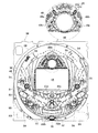
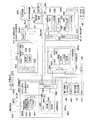
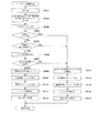
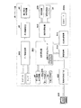
実施例1のパチンコ機を、図面に基づいて詳細に説明する。図1はパチンコ機10の正面図であり、図2は、パチンコ機10の遊技盤30の正面図であり、図3は、パチンコ機10の裏面図である。図4は、パチンコ機10の電気的構成を示すブロック図である。図5は、第3図柄表示装置42の表示内容を示す説明図である。   The pachinko machine of Example 1 is demonstrated in detail based on drawing. 1 is a front view of the pachinko machine 10, FIG. 2 is a front view of the game board 30 of the pachinko machine 10, and FIG. 3 is a back view of the pachinko machine 10. FIG. 4 is a block diagram showing an electrical configuration of the pachinko machine 10. FIG. 5 is an explanatory diagram showing the display contents of the third symbol display device 42.

図1に示すように、パチンコ機10は、当該パチンコ機10の外殻を形成し遊技場(ホール)の遊技島に固定される外枠11と、この外枠11の一側部(例えば正面視での左側部)を開閉軸として外枠11に対して開閉可能に支持された内枠12と、この内枠12の一側部(例えば正面視での左側部)を開閉軸として内枠12に対して開閉自在に取り付けられる前面枠セット14とを備えている。   As shown in FIG. 1, the pachinko machine 10 includes an outer frame 11 that forms an outer shell of the pachinko machine 10 and is fixed to a game island of a game hall (hole), and one side portion (for example, a front surface) of the outer frame 11. An inner frame 12 supported so as to be openable and closable with respect to the outer frame 11 with the left-hand side as viewed as an opening / closing axis, and an inner frame with one side portion (for example, the left-hand side as viewed from the front) of the inner frame 12 as an opening / closing axis. And a front frame set 14 that can be freely opened and closed.

外枠11は、木製の板材により全体として正面視で矩形状に構成され、小ネジ等の離脱可能な締結具により各板材が組み付けられている。本実施の形態では、例えば、外枠11の上下方向の外寸は809mm(内寸771mm)、左右方向の外寸は518mm(内寸480mm)となっている。なお、外枠11は樹脂やアルミニウム等の軽金属などにより構成されていてもよい。   The outer frame 11 is formed in a rectangular shape as a whole by a wooden plate material, and each plate material is assembled by a detachable fastener such as a machine screw. In the present embodiment, for example, the outer dimension of the outer frame 11 is 809 mm (inner dimension 771 mm), and the outer dimension in the left and right direction is 518 mm (inner dimension 480 mm). The outer frame 11 may be made of a light metal such as resin or aluminum.

図1に示すように、内枠12は、大別すると、その最下部に取り付けられた下皿ユニット13と、この下皿ユニット13よりも上側の範囲で内枠12の左側の上下方向の開閉軸を軸心にして開閉自在に取り付けられた前面枠セット14と、外形が矩形状の樹脂ベース(図示省略)に着脱自在に取り付けられる遊技盤30(図2参照)とを備えている。   As shown in FIG. 1, the inner frame 12 can be broadly divided into a lower tray unit 13 attached to the lowermost portion thereof, and a vertical opening on the left side of the inner frame 12 in a range above the lower tray unit 13. A front frame set 14 that is attached to be openable and closable around an axis is provided, and a game board 30 (see FIG. 2) that is detachably attached to a resin base (not shown) whose outer shape is rectangular.

図1に示すように、下皿ユニット13は、内枠12に対してネジ等の締結具により固定されている。この下皿ユニット13の前面側には、下皿15と球抜きレバー17と遊技球発射ハンドル18と音出力口24が設けられている。球受皿としての下皿15は、下皿ユニット13のほぼ中央部に設けられており、排出口16より排出された遊技球が下皿15内に貯留可能になっている。球抜きレバー17は、下皿15内の遊技球を抜くためのものであり、この球抜きレバー17を図1で左側に移動させることにより、下皿15の底面の所定箇所が開口され、下皿15内に貯留された遊技球を下皿15の底面の開口部分を通して下方向外部に抜くことができる。遊技球発射ハンドル18は、下皿15よりも右方で手前側に突出して配設されている。遊技者による遊技球発射ハンドル18の操作に応じて、遊技球発射装置38によって遊技球が後述する遊技盤30の方へ打ち込まれるようになっている。遊技球発射装置38は、例えば、遊技球発射ハンドル18と発射装置229(図4参照)などで構成されている。音出力口24は、下皿ユニット13内あるいは背面に設けられたスピーカからの音を出力するための出力口である。   As shown in FIG. 1, the lower plate unit 13 is fixed to the inner frame 12 by a fastener such as a screw. On the front side of the lower plate unit 13, a lower plate 15, a ball removal lever 17, a game ball launching handle 18, and a sound output port 24 are provided. The lower tray 15 as a ball receiving tray is provided at the substantially central portion of the lower tray unit 13, and the game balls discharged from the discharge port 16 can be stored in the lower tray 15. The ball removal lever 17 is for removing a game ball in the lower plate 15. By moving the ball removal lever 17 to the left in FIG. 1, a predetermined position on the bottom surface of the lower plate 15 is opened, The game balls stored in the dish 15 can be pulled out downward through the opening on the bottom surface of the lower dish 15. The game ball launching handle 18 is disposed so as to protrude to the front side on the right side of the lower plate 15. In accordance with the operation of the game ball launching handle 18 by the player, the game ball launching device 38 drives the game ball toward a game board 30 described later. The game ball launching device 38 includes, for example, a game ball launching handle 18 and a launching device 229 (see FIG. 4). The sound output port 24 is an output port for outputting sound from a speaker provided in the lower plate unit 13 or on the back surface.

また、前面枠セット14は、図1に示すように、内枠12に対して開閉可能に取り付けられており、内枠12と同様、パチンコ機10の正面からみて左側に上下に延びる開閉軸を軸心にして前方側に開放できるようになっている。   As shown in FIG. 1, the front frame set 14 is attached to the inner frame 12 so as to be openable and closable. Like the inner frame 12, the front frame set 14 has an open / close shaft extending vertically to the left when viewed from the front of the pachinko machine 10. It can be opened to the front side with an axial center.

図1に示すように、前面枠セット14の下部(上述の下皿15の上方位置)には、遊技球の受皿としての上皿19が一体的に設けられている。ここで、上皿19は、遊技球を一旦貯留し、一列に整列させながら遊技球発射装置38の方へ導出するための球受皿である。また、前面枠セット14には、遊技盤30の遊技領域30a(図2参照)のほとんどを外部から視認することができるよう略楕円形状の窓部101が形成されている。詳しくは、窓部101は、その左右側の略中央部が、上下側に比べて比較的緩やかに湾曲した形状となっている略楕円形状で中央が空洞とした枠体であり、その枠体の空洞部分に略楕円形状のガラス板137が取り付けられたものである。このガラス板137は二重ガラス構造としている。なお、窓部101の前記略中央部が直線状になるようにし、ガラス板137もその形状に合わせるようにしてもよい。また、ガラス板137は、ガラスに限定されず、所定の強度がある透明板であればその材質などは問わない。   As shown in FIG. 1, an upper plate 19 as a receiving tray for game balls is integrally provided at the lower portion of the front frame set 14 (above the lower plate 15). Here, the upper plate 19 is a ball receiving tray for temporarily storing the game balls and guiding them to the game ball launching device 38 while aligning them in a line. The front frame set 14 is formed with a substantially elliptical window 101 so that most of the game area 30a (see FIG. 2) of the game board 30 can be viewed from the outside. Specifically, the window portion 101 is a substantially oval shape whose substantially central portion on the left and right sides is curved relatively gently as compared with the upper and lower sides, and has a hollow in the center. A substantially elliptical glass plate 137 is attached to the hollow portion. This glass plate 137 has a double glass structure. The substantially central portion of the window 101 may be linear, and the glass plate 137 may be matched to the shape. The glass plate 137 is not limited to glass, and any material may be used as long as it is a transparent plate having a predetermined strength.

また、前面枠セット14は、図1に示すように、上皿19の左下側の箇所に、遊技者による操作指示(例えば、押下指示)を受ける枠ボタン20(演出ボタン)を備えている。図4に示すように、枠ボタン20はサブ制御装置262に接続されている。例えば、所定の操作有効条件成立時には、当該枠ボタン20の操作が有効となり、枠ボタン20を押下するなどにより、第3図柄表示装置42の画面表示が変化したり、出力音を変更したり、ランプ表示を変更したりするなど、遊技者が遊技に積極的に参加できるようになっている。   Further, as shown in FIG. 1, the front frame set 14 includes a frame button 20 (production button) that receives an operation instruction (for example, a pressing instruction) by a player at a location on the lower left side of the upper plate 19. As shown in FIG. 4, the frame button 20 is connected to the sub-control device 262. For example, when a predetermined operation valid condition is established, the operation of the frame button 20 becomes valid, and the screen display of the third symbol display device 42 is changed, the output sound is changed by pressing the frame button 20, etc. The player can actively participate in the game, such as changing the lamp display.

加えて、前面枠セット14は、その前面側で窓部101の周囲(例えばコーナー部分)に各種ランプ等の発光手段が設けられている。これら発光手段は、大当たり時や所定のリーチ時等における遊技状態の変化に応じて点灯、点滅のように発光態様が変更制御され遊技中の演出効果を高める役割を果たすものである。例えば、窓部101の周縁には、LED等の発光手段を内蔵した環状電飾部102が左右対称に設けられ、該環状電飾部102の中央であってパチンコ機10の最上部には、同じくLED等の発光手段を内蔵した中央電飾部103が設けられている。本パチンコ機10では、中央電飾部103が大当たりランプとして機能し、大当たり時に点灯や点滅を行うことにより、大当たり中であることを報知する。その他、中央電飾部103の左右側方には、賞球払出し中に点灯する賞球ランプ105と所定のエラー時に点灯するエラー表示ランプ106とが設けられている。また、環状電飾部102の下端部に隣接するようにして、内枠12表面や遊技盤30表面等の一部を視認できるよう透明樹脂からなる小窓107が設けられている。この小窓107の所定箇所を平面状としているので、遊技盤30の右下隅部に貼り付けられた証紙などを、小窓107の当該平面状箇所から機械で好適に読み取ることができる。   In addition, the front frame set 14 is provided with light emitting means such as various lamps around the window portion 101 (for example, a corner portion) on the front side. These light emitting means play a role of enhancing the effect of the game during the game by changing and controlling the light emission mode such as lighting and blinking according to the change of the game state at the time of big hit or predetermined reach. For example, at the periphery of the window portion 101, an annular illumination portion 102 containing a light emitting means such as an LED is provided symmetrically, and at the center of the annular illumination portion 102 and at the top of the pachinko machine 10, Similarly, a central illumination unit 103 having a built-in light emitting means such as an LED is provided. In the pachinko machine 10, the central illumination unit 103 functions as a jackpot lamp, and lights and blinks when the jackpot is informed that the jackpot is being hit. In addition, on the left and right sides of the central illumination unit 103, there are provided a prize ball lamp 105 that is lit during the payout of a prize ball and an error display lamp 106 that is lit when a predetermined error occurs. Further, a small window 107 made of a transparent resin is provided so as to be adjacent to the lower end portion of the annular illumination portion 102 so that a part of the inner frame 12 surface, the game board 30 surface, or the like can be visually recognized. Since the predetermined portion of the small window 107 is flat, the certificate paper or the like attached to the lower right corner of the game board 30 can be suitably read from the flat portion of the small window 107 by a machine.

また、窓部101の下方には貸球操作部120が配設されており、貸球操作部120には球貸しボタン121と、返却ボタン122と、度数表示部123とが設けられている。パチンコ機10の側方に配置された図示しないカードユニット(球貸しユニット)に紙幣やカード等を投入した状態で貸球操作部120が操作されると、その操作に応じて遊技球の貸出が行われる。球貸しボタン121は、カード等(記録媒体)に記録された情報に基づいて貸出球を得るために操作されるものであり、カード等に残額が存在する限りにおいて貸出球が上皿19に供給される。返却ボタン122は、カードユニットに挿入されたカード等の返却を求める際に操作される。度数表示部123はカード等の残額情報を表示するものである。なお、カードユニットを介さずに球貸し装置等から上皿に遊技球が直接貸し出されるパチンコ機、いわゆる現金機では貸球操作部120が不要となる。故に、貸球操作部120の設置部分に、飾りシール等が付されるようになっている。これにより、カードユニットを用いたパチンコ機と現金機との貸球操作部の共通化が図れる。   In addition, a ball lending operation unit 120 is disposed below the window unit 101, and the ball lending operation unit 120 is provided with a ball lending button 121, a return button 122, and a frequency display unit 123. When the ball lending operation unit 120 is operated with a bill or a card inserted in a card unit (ball lending unit) (not shown) arranged on the side of the pachinko machine 10, a game ball is lent according to the operation. Done. The ball lending button 121 is operated to obtain a lending ball based on information recorded on a card or the like (recording medium), and the lending ball is supplied to the upper plate 19 as long as there is a remaining amount on the card or the like. Is done. The return button 122 is operated when requesting the return of a card or the like inserted into the card unit. The frequency display unit 123 displays remaining amount information such as a card. It should be noted that the ball rental operation unit 120 is not necessary for a pachinko machine in which game balls are lent directly to the upper plate from a ball lending device or the like without using a card unit, that is, a so-called cash machine. Therefore, a decorative seal or the like is attached to the installation portion of the ball rental operation unit 120. Thereby, the common use of the lending operation unit of the pachinko machine using the card unit and the cash machine can be achieved.

遊技盤30は、図2に示すように、四角形状の合板よりなり、その周縁部が内枠12の樹脂ベース(図示省略)の裏側に当接した状態で取着されており、この遊技盤30の前面側の略中央部分たる遊技領域30aが樹脂ベースの略円形状の図1に示した窓部101(ガラス板137)を通じて内枠12の前面側に露出した状態となっている。   As shown in FIG. 2, the game board 30 is made of a rectangular plywood, and its peripheral portion is attached in contact with the back side of a resin base (not shown) of the inner frame 12. A gaming area 30a, which is a substantially central portion on the front side of the front side 30, is exposed to the front side of the inner frame 12 through the resin-based substantially circular window portion 101 (glass plate 137) shown in FIG.

次に、図2を用いて遊技盤30の構成を説明する。遊技盤30は、一般入賞口31、可変入賞装置32、第1の始動口33a,33b(例えば作動チャッカ)、第2の始動口34(例えばスルーゲート)、可変表示装置ユニット35等を備えている。これらの一般入賞口31、可変入賞装置32、第1の始動口33a,33b(例えば作動チャッカ)、第2の始動口34(例えばスルーゲート)、可変表示装置ユニット35等は、遊技盤30における、ルータ加工によって形成された各貫通穴にそれぞれに配設され、遊技盤30前面側から木ネジ等により取り付けられている。前述の一般入賞口31、可変入賞装置32および第1の始動口33a,33bに遊技球が入球し、当該入球が後述する検出スイッチ(入賞口スイッチ、カウントスイッチ、作動口スイッチ)で検出され、この検出スイッチの出力に基づいて、上皿19(または下皿15)へ所定数の賞品球が払い出される。なお、前述したように、上部側の第1の始動口33aには作動口スイッチ(通過検出スイッチ)が設けられ、この第1の始動口33aへの入球をその作動口スイッチにより検出されるようになっている。また、下部側の第1の始動口33bにも作動口スイッチ(通過検出スイッチ)が設けられ、この第1の始動口33bへの入球をその作動口スイッチにより検出されるようになっている。すなわち、上部側の第1の始動口33aへの遊技球の入球または下部側の第1の始動口33bへの遊技球の入球のどちらの場合にも、それが始動入賞であることに変わりは無い。なお、上部側の第1の始動口33aと下部側の第1の始動口33bとは、図2示すように、単一の始動入賞装置33で構成されている。   Next, the configuration of the game board 30 will be described with reference to FIG. The game board 30 includes a general winning port 31, a variable winning device 32, first starting ports 33a and 33b (for example, operation chucker), a second starting port 34 (for example, a through gate), a variable display unit 35, and the like. Yes. These general winning port 31, variable winning device 32, first starting ports 33a and 33b (for example, operation chucker), second starting port 34 (for example, through gate), variable display unit 35, etc. Each of the through holes formed by router processing is disposed in each through hole, and is attached from the front side of the game board 30 with a wood screw or the like. A game ball enters the aforementioned general winning port 31, variable winning device 32, and first start ports 33a and 33b, and the detected balls are detected by detection switches (winning port switch, count switch, operation port switch) described later. Based on the output of the detection switch, a predetermined number of prize balls are paid out to the upper plate 19 (or the lower plate 15). As described above, the first start port 33a on the upper side is provided with an operation port switch (passage detection switch), and a ball entering the first start port 33a is detected by the operation port switch. It is like that. Further, the first start port 33b on the lower side is also provided with an operation port switch (passage detection switch), and the ball entering the first start port 33b is detected by the operation port switch. . That is, in either case of entering a game ball into the first start port 33a on the upper side or entering a game ball into the first start port 33b on the lower side, it is a start prize. There is no change. The upper first start port 33a and the lower first start port 33b are constituted by a single start winning device 33 as shown in FIG.

その他に、図2に示すように、遊技盤30にはアウト口36が設けられており、各種入賞装置等に入球しなかった遊技球はこのアウト口36を通って図示しない球排出路の方へと案内されるようになっている。遊技盤30には、遊技球の落下方向を適宜分散、調整等するために多数の釘が植設されているとともに、風車37等の各種部材(役物)が配設されている。   In addition, as shown in FIG. 2, the game board 30 is provided with an out port 36, and game balls that have not entered the various winning devices or the like pass through the out port 36 in a ball discharge path (not shown). You will be guided to the direction. A number of nails are planted on the game board 30 in order to appropriately disperse and adjust the falling direction of the game balls, and various members (acts) such as the windmill 37 are arranged.

可変表示装置ユニット35は、第1の始動口33a,33bへの入賞をトリガとして、識別情報としての第1図柄(例えば特別図柄)を変動表示する第1図柄表示装置40と、第2の始動口34の通過をトリガとして、第2図柄(例えば普通図柄)を変動表示する第2図柄表示装置41と、第1の始動口33a,33bへの入賞をトリガとして、第3図柄(例えば装飾図柄)を変動表示する第3図柄表示装置42とを備えている。   The variable display device unit 35 includes a first symbol display device 40 for variably displaying a first symbol (for example, a special symbol) as identification information, triggered by winning in the first start ports 33a and 33b, and a second start. With the passage of the mouth 34 as a trigger, the second symbol display device 41 that variably displays the second symbol (for example, a normal symbol) and the winning of the first start ports 33a and 33b as a trigger, the third symbol (for example, a decorative symbol) ) In a variable manner.

第1図柄表示装置40は、例えば、複数個(本実施例では2個)の2色発光タイプのLED(発光ダイオード)40a,40bと、このLED40a,40bでの変動表示の保留数を示す保留ランプ40cとを備えている。このLED40a,40bは、例えば、赤色と青色に発光可能なものである。第1図柄表示装置40は、各LED40a,40bの発光色を交互に変更させることで、第1図柄(本実施例では各LED40a,40bの発光色態様)の変動表示状態を発生させ、例えば、両方のLED40a,40bが赤色発光状態で停止すると確変大当り(特定当り)を示し、両方のLED40a,40bが青色発光状態で停止すると通常大当り(非特定当り)を示し、両方のLED40a,40bが互いに異なる色の発光状態で停止すると外れを示す。   The first symbol display device 40 includes, for example, a plurality (two in this embodiment) of two-color light emitting type LEDs (light emitting diodes) 40a and 40b, and a hold indicating the number of hold of the variable display on the LEDs 40a and 40b. And a lamp 40c. The LEDs 40a and 40b can emit light in red and blue, for example. The first symbol display device 40 generates a variable display state of the first symbol (in this embodiment, the emission color mode of each LED 40a, 40b) by alternately changing the emission color of each LED 40a, 40b, for example, When both LEDs 40a and 40b stop in a red light emitting state, a probable big hit (specific hit) is indicated, and when both LEDs 40a and 40b stop in a blue light emitting state, a normal big hit (non-specific hit) is indicated, and both LEDs 40a and 40b are mutually connected. When it stops in the light emission state of a different color, it will show off.

なお、この第1図柄表示装置40として、少なくとも3色以上の発光が可能なタイプの単一のLEDを採用してもよく、各色の発光を交互などに行うようにすることで、第1図柄の変動表示状態を発生させ、LEDが第1の色の発光状態で停止すると確変大当り(特定当り)を示し、LEDが第2の色の発光状態で停止すると通常大当り(非特定当り)を示し、LEDが第3の色の発光状態で停止すると外れを示すようにしてもよい。なお、上述した第1図柄表示装置40が本発明における識別情報変動表示手段に相当する。   In addition, as this 1st symbol display apparatus 40, you may employ | adopt the single LED of the type which can light-emit at least 3 colors or more, and by performing light emission of each color alternately, the 1st symbol is displayed. When the LED stops in the light emission state of the first color, it shows a probable big hit (specific hit), and when the LED stops in the light emission state of the second color, it usually shows a big hit (non-specific hit) When the LED stops in the light emission state of the third color, it may be indicated that the LED has come off. The first symbol display device 40 described above corresponds to the identification information fluctuation display means in the present invention.

第2図柄表示装置41は、第2図柄用としての例えば「○」が描かれた表示部41aと、第2図柄用としての例えば「×」が描かれた表示部41bと、保留ランプ41cとを有し、遊技球が第2の始動口34を通過する毎に例えば表示部41a,41bによる表示図柄(普通図柄)が変動し、その変動表示が所定図柄で停止した場合に下部側の第1の始動口33bが所定時間だけ作動状態となる(開放される)よう構成されている。遊技球が第2の始動口34を通過した回数は最大4回まで保留され、その保留回数が保留ランプ41cにて点灯表示されるようになっている。なお、表示部41a,41bは、その内部にLED(発光ダイオード)を有しており、このLEDの発光(あるいはランプの点灯)を切り換えることにより変動表示される構成としている。なお、上述した第2図柄表示装置41が本発明における普通識別情報変動表示手段に相当する。   The second symbol display device 41 includes, for example, a display unit 41a on which “○” is drawn for the second symbol, a display unit 41b on which “x” is drawn for the second symbol, and a holding lamp 41c. When the game ball passes through the second starting port 34, for example, the display symbols (ordinary symbols) displayed by the display units 41a and 41b change, and when the change display stops at a predetermined symbol, the lower side One start port 33b is configured to be in an activated state (opened) for a predetermined time. The number of times that the game ball has passed through the second start port 34 is held up to a maximum of 4 times, and the number of times the game ball is held is lit on the hold lamp 41c. The display units 41a and 41b have LEDs (light emitting diodes) inside thereof, and are configured to be variably displayed by switching the light emission of the LEDs (or lighting of the lamps). The second symbol display device 41 described above corresponds to the normal identification information fluctuation display means in the present invention.

第3図柄表示装置42は、例えば液晶表示装置で構成されており、後述する表示制御装置45により表示内容が制御される。第3図柄表示装置42には、例えば後述する図5に示すように、左、中及び右の3つの装飾図柄列L,M,Rが表示される。各装飾図柄列L,M,Rは複数の装飾図柄によって構成されており、これら装飾図柄が装飾図柄列L,M,R毎にスクロールされるようにして第3図柄表示装置42に可変表示されるようになっている。なお本実施の形態では、第3図柄表示装置42(液晶表示装置)は、例えば、9.3インチサイズの大型の液晶ディスプレイを備える。可変表示装置ユニット35には、第3図柄表示装置42を囲むようにしてセンターフレーム47が配設されている。なお、上述した第3図柄表示装置42が本発明における装飾識別情報(図柄)変動表示手段に相当し、上述した表示制御装置45が本発明における表示制御手段に相当する。   The 3rd symbol display apparatus 42 is comprised, for example with the liquid crystal display device, and the display content is controlled by the display control apparatus 45 mentioned later. On the third symbol display device 42, for example, as shown in FIG. 5 described later, three decorative symbol rows L, M, and R on the left, middle, and right are displayed. Each of the decorative symbol rows L, M, R is composed of a plurality of decorative symbols, and these decorative symbols are variably displayed on the third symbol display device 42 so as to be scrolled for each of the decorative symbol rows L, M, R. It has become so. In the present embodiment, the third symbol display device 42 (liquid crystal display device) includes, for example, a large 9.3 inch size liquid crystal display. The variable display device unit 35 is provided with a center frame 47 so as to surround the third symbol display device 42. The above-described third symbol display device 42 corresponds to decoration identification information (design) variation display means in the present invention, and the above-described display control device 45 corresponds to display control means in the present invention.

図2に示すように、可変入賞装置32は、通常は遊技球が入賞できない又は入賞し難い閉状態になっており、大当たりの際に遊技球が入賞しやすい開状態と通常の閉状態とに繰り返し作動されるものである。このように、大当たりの際に可変入賞装置32が開状態と通常の閉状態とに繰り返し作動される状態は、特別遊技状態(例えば、大当り状態)と呼ばれ、可変入賞装置32に多数の遊技球が入球(入賞)し、その入賞に対して大量の遊技球が賞球払い出しされることから、遊技者にとって有利な遊技状態となっている。   As shown in FIG. 2, the variable winning device 32 is normally in a closed state in which a game ball cannot be won or difficult to win, and is in an open state in which a game ball is easy to win in the case of a big win and a normal closed state. It is operated repeatedly. As described above, a state in which the variable winning device 32 is repeatedly operated in an open state and a normal closed state in the case of a big win is called a special game state (for example, a big win state). Since the ball enters (wins) and a lot of game balls are paid out for the winning, the game state is advantageous to the player.

より詳しくは、第1の始動口33a,33bに対し遊技球が入賞すると第1図柄表示装置40の2個のLED40a,40bが変動表示され、その変動停止後のLED40a,40bの表示が予め設定した発光態様の組合せとなった場合に特別遊技状態が発生する。例えば、両方のLED40a,40bが赤色発光状態で停止するという発光態様の場合には、確変大当り(特定当り)の特別遊技状態に当選したことを示し、両方のLED40a,40bが青色発光状態で停止するという発光態様の場合には、通常大当り(非特定当り)の特別遊技状態に当選したことを示し、両方のLED40a,40bが互いに異なる色の発光状態で停止するという発光態様の場合には外れ(特別遊技状態に落選したこと)を示す。   More specifically, when a game ball wins the first start opening 33a, 33b, the two LEDs 40a, 40b of the first symbol display device 40 are displayed in a variable manner, and the display of the LEDs 40a, 40b after the change stop is preset. The special gaming state occurs when the combination of the light emission modes is achieved. For example, in the case of a light emitting mode in which both LEDs 40a and 40b are stopped in a red light emitting state, it indicates that a special gaming state with a probable big hit (specific hit) is won, and both LEDs 40a and 40b are stopped in a blue light emitting state. In the case of the light-emitting mode, it means that the special game state of the big hit (non-specific hit) is normally won, and in the case of the light-emitting mode in which both LEDs 40a and 40b are stopped in the light-emitting states of different colors. (You have lost the special game state).

そして、可変入賞装置32は、その大入賞口32aが所定の開放状態となり、遊技球が入賞しやすい状態(大当たり状態)になるよう構成されている。具体的には、当該開放状態についての所定時間の経過又は所定個数の入賞を1ラウンドとして、可変入賞装置32の大入賞口32aが所定回数(ラウンド数)繰り返し開放される。遊技球が第1の始動口33a,33bを通過した回数は最大4回まで保留され、その保留回数が保留ランプ40cにて点灯表示されるようになっている。なお、保留ランプ40cは、第3図柄表示装置42の表示画面の一部で保留表示等される構成等であっても良い。   The variable winning device 32 is configured such that the large winning opening 32a is in a predetermined open state, and the game ball is likely to win (a big hit state). Specifically, the special winning opening 32a of the variable winning device 32 is repeatedly opened a predetermined number of times (the number of rounds) with the passage of a predetermined time or a predetermined number of winnings in the open state as one round. The number of times that the game ball has passed through the first start ports 33a and 33b is held up to a maximum of 4 times, and the number of times that the game ball is held is lit and displayed by the hold lamp 40c. Note that the hold lamp 40c may be configured such that a hold display is performed on a part of the display screen of the third symbol display device 42.

また、遊技盤30には、図2に示すように、遊技球発射装置38(図3参照)から発射された遊技球を遊技盤30上部へ案内するためのレールユニット50が取り付けられており、遊技球発射ハンドル18の回動操作に伴い発射された遊技球はレールユニット50の後述する球案内通路49を通じて所定の遊技領域30aに案内されるようになっている。レールユニット50はリング状をなす樹脂成型品(例えば、フッ素樹脂が添加されて成形されたもの)にて構成されており、内外二重に一体形成された内レール51と外レール52とを有する。内レール51は上方の約1/4ほどを除いて略円環状に形成され、一部(主に左側部)が内レール51に向かい合うようにして外レール52が形成されている。かかる場合、内レール51と外レール52とにより誘導レールが構成され、これら各レール51,52が所定間隔を隔てて並行する部分(向かって左側の部分)により球案内通路49が形成されている。なお、球案内通路49は、遊技盤30との当接面を有した溝状、すなわち手前側を開放した溝状に形成されている。   Further, as shown in FIG. 2, a rail unit 50 for guiding the game ball launched from the game ball launcher 38 (see FIG. 3) to the upper part of the game board 30 is attached to the game board 30. A game ball launched in accordance with the turning operation of the game ball launch handle 18 is guided to a predetermined game area 30a through a ball guide passage 49 (to be described later) of the rail unit 50. The rail unit 50 is formed of a ring-shaped resin molded product (for example, a molded product added with fluororesin), and has an inner rail 51 and an outer rail 52 that are integrally formed in an inner and outer double. . The inner rail 51 is formed in a substantially annular shape except for about 1/4 of the upper part, and the outer rail 52 is formed so that a part (mainly the left side) faces the inner rail 51. In such a case, a guide rail is constituted by the inner rail 51 and the outer rail 52, and a ball guide passage 49 is formed by a portion (the left portion toward the left) where the rails 51 and 52 are parallel to each other at a predetermined interval. . The ball guide passage 49 is formed in a groove shape having a contact surface with the game board 30, that is, a groove shape in which the front side is opened.

内レール51の先端部分(図2の左上部)には戻り球防止部材53が取着されている。これにより、一旦、内レール51及び外レール52間の球案内通路49から遊技盤30の上部へと案内された遊技球が再度球案内通路49内に戻ってしまうといった事態が防止されるようになっている。また、外レール52には、遊技球の最大飛翔部分に対応する位置(図2の右上部:外レール52の先端部に相当する部位)に返しゴム54が取着されている。従って、所定以上の勢いで発射された遊技球は、返しゴム54に当たって跳ね返されるようになっている。外レール52の内側面には、遊技球の飛翔をより滑らかなものとするべく、つまり遊技球の摩擦抵抗を少なくするべく、長尺状をなすステンレス製の金属帯としての摺動プレート55が取着されている。   A return ball preventing member 53 is attached to the tip portion of the inner rail 51 (the upper left portion in FIG. 2). This prevents a situation in which the game ball once guided from the ball guide passage 49 between the inner rail 51 and the outer rail 52 to the upper portion of the game board 30 returns to the ball guide passage 49 again. It has become. Further, a return rubber 54 is attached to the outer rail 52 at a position corresponding to the maximum flight portion of the game ball (upper right portion in FIG. 2: a portion corresponding to the tip portion of the outer rail 52). Therefore, the game ball fired at a predetermined momentum or more hits the return rubber 54 and is bounced back. On the inner surface of the outer rail 52, there is a sliding plate 55 as a long metal strip made of stainless steel to make the flight of the game ball smoother, that is, to reduce the frictional resistance of the game ball. It is attached.

また、レールユニット50の外周部には、正面視した状態で周囲外方へ張り出した円弧状のフランジ56が形成されている。フランジ56は、遊技盤30に対する取付面を構成する。レールユニット50が遊技盤30に取り付けられる際には、遊技盤30上にフランジ56が当接され、その状態で、当該フランジ56に形成された複数の透孔にネジ等が挿通されて遊技盤30に対するレールユニット50の締結がなされるようになっている。   Further, an arc-shaped flange 56 is formed on the outer peripheral portion of the rail unit 50 so as to project outward from the periphery when viewed from the front. The flange 56 constitutes a mounting surface for the game board 30. When the rail unit 50 is attached to the game board 30, the flange 56 is brought into contact with the game board 30, and in this state, screws or the like are inserted into a plurality of through holes formed in the flange 56. The rail unit 50 is fastened to 30.

さらに本実施の形態では、正面から見てレールユニット50の上下左右の各端部は略直線状に(平坦に)形成されている。つまり、レールユニット50の上下左右の各端部においてはフランジ56が切り落とされ、パチンコ機10における有限の領域にてレール径の拡張、すなわち遊技盤30上の遊技領域30aの拡張が図られるようになっている。   Furthermore, in the present embodiment, the top, bottom, left, and right ends of the rail unit 50 are formed in a substantially straight line (flat) when viewed from the front. That is, the flange 56 is cut off at each of the upper, lower, left and right ends of the rail unit 50 so that the rail diameter can be expanded in a limited area in the pachinko machine 10, that is, the game area 30a on the game board 30 can be expanded. It has become.

内レール51及び外レール52間の球案内通路49の入口には、当該球案内通路49の一部を閉鎖するようにして凸部57が形成されている。この凸部57は、内レール51からレールユニット50下端部にかけて略鉛直方向に設けられ、遊技領域30aまで至らず球案内通路49内を逆流してくるファール球を内枠12に設けられたファール球通路(図示省略)に導くための役目をなす。なお、遊技盤30の右下隅部及び左下隅部は、証紙(例えば製造番号が記載されている)等のシール(図2のS1,S2)やプレートを貼着するためのスペースとなっており、この貼着スペースを確保するために、フランジ56に切欠58,59が形成されている。遊技盤30の右下隅部や左下隅部に、証紙等のシール(図2のS1,S2)を貼着することで、遊技盤30と証紙との一義性を持たせることができる。   A convex portion 57 is formed at the entrance of the ball guide passage 49 between the inner rail 51 and the outer rail 52 so as to close a part of the ball guide passage 49. The convex portion 57 is provided in a substantially vertical direction from the inner rail 51 to the lower end portion of the rail unit 50, and a foul ball that does not reach the game area 30 a and flows backward in the ball guide passage 49 is provided on the inner frame 12. It plays a role of guiding to a ball passage (not shown). Note that the lower right corner and the lower left corner of the game board 30 are spaces for attaching stickers (eg, S1 and S2 in FIG. 2) and plates such as certificate stamps (for example, serial numbers are described). In order to secure this adhering space, notches 58 and 59 are formed in the flange 56. By sticking a sticker such as a certificate (S1, S2 in FIG. 2) to the lower right corner or the lower left corner of the game board 30, the game board 30 and the certificate can be uniquely defined.

次に、遊技盤30の遊技領域30aについて説明する。遊技領域30aは、図2に示すように、レールユニット50の内周部(内外レール)により略円形状に区画形成されており、特に本実施の形態では、遊技盤30の盤面上に区画される当該遊技領域30aが従来よりもはるかに大きく構成されている。本実施の形態では、外レール52の最上部地点から遊技盤30下部までの間の距離は445mm(従来品よりも58mm長い)、外レール52の極左位置から内レール51の極右位置までの間の距離は435mm(従来品よりも50mm長い)となっている。また、内レール51の極左位置から内レール51の極右位置までの間の距離は418mmとなっている。   Next, the game area 30a of the game board 30 will be described. As shown in FIG. 2, the game area 30 a is partitioned into a substantially circular shape by the inner peripheral portion (inner and outer rails) of the rail unit 50. In particular, in the present embodiment, the game area 30 a is partitioned on the board surface of the game board 30. The game area 30a is configured to be much larger than before. In the present embodiment, the distance between the uppermost point of the outer rail 52 and the lower part of the game board 30 is 445 mm (58 mm longer than the conventional product), and is from the extreme left position of the outer rail 52 to the extreme right position of the inner rail 51. The distance is 435 mm (50 mm longer than the conventional product). The distance from the extreme left position of the inner rail 51 to the extreme right position of the inner rail 51 is 418 mm.

本実施の形態では、遊技領域30aを、パチンコ機10の正面から見て、内レール51及び外レール52によって囲まれる領域のうち、内外レール51,52の並行部分である誘導レールの領域を除いた領域としている。従って、遊技領域30aと言った場合には誘導レール部分は含まないため、遊技領域30aの向かって左側限界位置は外レール52によってではなく内レール51によって特定される。同様に、遊技領域30aの向かって右側限界位置は内レール51によって特定される。また、遊技領域30aの下側限界位置は遊技盤30の下端位置によって特定される。また、遊技領域30aの上側限界位置は外レール52によって特定される。   In the present embodiment, the game area 30a is viewed from the front of the pachinko machine 10, and the area of the guide rail that is a parallel part of the inner and outer rails 51 and 52 is excluded from the area surrounded by the inner rail 51 and the outer rail 52. As an area. Accordingly, when the game area 30 a is referred to, the guide rail portion is not included, and therefore the left limit position toward the game area 30 a is specified by the inner rail 51, not by the outer rail 52. Similarly, the right limit position toward the game area 30 a is specified by the inner rail 51. Further, the lower limit position of the game area 30 a is specified by the lower end position of the game board 30. The upper limit position of the game area 30 a is specified by the outer rail 52.

従って、本実施の形態では、遊技領域30aの幅(左右方向の最大幅)は、418mmであり、遊技領域30aの高さ(上下方向の最大幅)は、445mmである。   Therefore, in the present embodiment, the width (maximum width in the left-right direction) of the game area 30a is 418 mm, and the height (maximum width in the vertical direction) of the game area 30a is 445 mm.

なお、詳しい図面の開示は省略するが、遊技球発射装置38には、前面枠セット14側の球出口(上皿19の最下流部より通じる球出口)から遊技球が1つずつ供給される。   Although detailed disclosure of the drawings is omitted, game balls are supplied to the game ball launcher 38 one by one from the ball outlet on the front frame set 14 side (the ball outlet leading from the most downstream portion of the upper plate 19). .

次に、パチンコ機10の背面の構成について説明する。図3に示すように、パチンコ機10は、その背面(実際には内枠12及び遊技盤30の背面)において、各種制御基板が上下左右に並べられるようにして又は前後に重ねられるようにして配置されており、さらに、遊技球を供給するための遊技球供給装置(払出機構部352)や樹脂製の保護カバー等が取り付けられている。本実施の形態では、各種制御基板を2つの取付台に分けて搭載して2つの制御基板ユニットを構成し、それら制御基板ユニットを個別に内枠12又は遊技盤30の裏面に装着するようにしている。この場合、後述する図4に示した主制御装置261とサブ制御装置262とを一方の取付台(図示省略)に搭載してユニット化すると共に、後述する図4に示した払出制御装置311、発射制御装置312及び電源装置313を他方の取付台(図示省略)に搭載してユニット化している。ここでは便宜上、前者のユニットを「第1制御基板ユニット201」と称し、後者のユニットを「第2制御基板ユニット202」と称することとする。   Next, the configuration of the back surface of the pachinko machine 10 will be described. As shown in FIG. 3, the pachinko machine 10 is configured such that various control boards are arranged vertically or horizontally on the back surface (actually the back surface of the inner frame 12 and the game board 30) or stacked in front and back. Further, a game ball supply device (payout mechanism portion 352) for supplying game balls, a protective cover made of resin, and the like are attached. In this embodiment, various control boards are divided into two mounting bases to form two control board units, and these control board units are individually attached to the inner frame 12 or the back of the game board 30. ing. In this case, the main controller 261 and the sub controller 262 shown in FIG. 4 to be described later are mounted on one mounting base (not shown) to form a unit, and the payout controller 311 shown in FIG. 4 to be described later. The launch control device 312 and the power supply device 313 are mounted on the other mounting base (not shown) to form a unit. Here, for convenience, the former unit is referred to as “first control board unit 201”, and the latter unit is referred to as “second control board unit 202”.

また、払出機構部352及び保護カバーも1ユニットとして一体化されており、一般に樹脂部分を裏パックと称することもあるため、ここではそのユニットを「裏パックユニット203」と称する。各ユニット201〜203の詳細な構成については後述する。   Further, since the dispensing mechanism 352 and the protective cover are also integrated as one unit, and the resin portion is generally referred to as a back pack, the unit is referred to as a “back pack unit 203” here. The detailed configuration of each unit 201 to 203 will be described later.

第1制御基板ユニット201、第2制御基板ユニット202及び裏パックユニット203は、ユニット単位で何ら工具等を用いずに着脱できるよう構成されており、さらにこれに加え、一部に支軸部を設けて内枠12又は遊技盤30の裏面に対して開閉できる構成となっている。これは、各ユニット201〜203やその他構成が前後に重ねて配置されても、隠れた構成等を容易に確認することを可能とするための工夫でもある。   The first control board unit 201, the second control board unit 202, and the back pack unit 203 are configured so that they can be attached and detached without using any tools or the like in units of units. It is provided and can be opened and closed with respect to the inner frame 12 or the back surface of the game board 30. This is also a device for making it possible to easily check a hidden configuration or the like even if the units 201 to 203 and other configurations are arranged one behind the other.

また、遊技盤30の裏面には、各種入賞口などの遊技球の通過を検出するための入賞感知機構などが設けられている。具体的には、遊技盤30表側の一般入賞口31に対応する位置には入賞口スイッチが設けられ、可変入賞装置32にはカウントスイッチが設けられている。カウントスイッチは入賞球をカウントするスイッチである。また、第1の始動口33a,33bに対応する位置には作動口スイッチがそれぞれ設けられ、第1の始動口33a,33bへの遊技球の入球を当該作動口スイッチで検出される。第2の始動口34に対応する位置にはゲートスイッチが設けられ、第2の始動口34への遊技球の通過を当該作動口スイッチで検出される。ている。なお、上述した作動口スイッチが本発明における入賞検出手段に相当する。   In addition, on the back surface of the game board 30, a winning detection mechanism for detecting the passage of game balls such as various winning holes is provided. Specifically, a prize opening switch is provided at a position corresponding to the general prize opening 31 on the front side of the game board 30, and the variable prize winning device 32 is provided with a count switch. The count switch is a switch for counting winning balls. In addition, operation port switches are provided at positions corresponding to the first start ports 33a and 33b, respectively, and the entry of game balls into the first start ports 33a and 33b is detected by the operation port switches. A gate switch is provided at a position corresponding to the second starting port 34, and the passage of the game ball to the second starting port 34 is detected by the operating port switch. ing. The operating port switch described above corresponds to the winning detection means in the present invention.

入賞口スイッチ及びゲートスイッチは、図示しない電気配線を通じて盤面接続基板(図示省略)に接続され、さらにこの盤面接続基板が後述する主制御装置261内の主制御基板261a(図4参照)に接続されている。また、カウントスイッチは大入賞口中継端子基板(図示省略)に接続され、さらにこの大入賞口中継端子基板(図示省略)がやはり主制御基板261aに接続されている。これに対し、作動口スイッチは中継基板を介さずに直接に主制御基板261aに接続されている。   The prize opening switch and the gate switch are connected to a board connection board (not shown) through electrical wiring (not shown), and this board connection board is further connected to a main control board 261a (see FIG. 4) in a main controller 261 described later. ing. Further, the count switch is connected to a large winning opening relay terminal board (not shown), and this large winning opening relay terminal board (not shown) is also connected to the main control board 261a. On the other hand, the operation port switch is directly connected to the main control board 261a without going through the relay board.

その他図示は省略するが、可変入賞装置32には、大入賞口32aを開放するための大入賞口ソレノイドが設けられ、下部側の第1の始動口33bには、電動役物を開放するための作動口ソレノイドが設けられている。   Although not shown in the drawings, the variable prize winning device 32 is provided with a big prize opening solenoid for opening the big prize opening 32a, and the lower first start opening 33b is used for opening the electric accessory. Is provided.

上記入賞感知機構にて各々検出された検出結果は、後述する主制御装置261内の主制御基板261aに取り込まれ、該主制御基板261aよりその都度の入賞状況に応じた払出指令(遊技球の払出個数)が払出制御基板311aに送信される。そして、該払出制御基板311aの出力により所定数の遊技球の払出が実施される。かかる場合、各種入賞口に入賞した遊技球を入賞球処理装置に一旦集め、その入賞球処理装置で入賞球の存在を1つずつ順番に確認した上で払出を行う従来方式(いわゆる証拠球方式)とは異なり、本実施の形態のパチンコ機10では、各種入賞口毎に遊技球の入賞を電気的に感知して払出が直ちに行われる(すなわち、本パチンコ機10では入賞球処理装置を廃止している)。故に、払い出す遊技球が多量にあっても、その払出をいち早く実施することが可能となる。但し、本発明に従来の「証拠球方式」を適用してもよい。   The detection results detected by the winning detection mechanism are taken into a main control board 261a in a main control device 261, which will be described later, and the main control board 261a issues a payout command (a game ball of each game ball) according to the winning situation each time. The number of payouts) is transmitted to the payout control board 311a. Then, a predetermined number of game balls are paid out by the output of the payout control board 311a. In such a case, a conventional method (so-called evidence ball method) in which game balls won in various winning openings are once collected in a winning ball processing device and paid out after the winning ball processing device confirms the presence of winning balls one by one in order. Unlike the above, in the pachinko machine 10 according to the present embodiment, the winning of a game ball is electrically detected for each winning opening and the payout is immediately made (that is, the winning ball processing apparatus is abolished in the pachinko machine 10). is doing). Therefore, even if there are a lot of game balls to be paid out, the payout can be carried out quickly. However, the conventional “evidence ball system” may be applied to the present invention.

第1制御基板ユニット201は略L字状をなす取付台(図示省略)を有し、この取付台に主制御装置261とサブ制御装置262とが搭載されている。ここで、主制御装置261は、図4に示すように、主たる制御を司るCPU501と、遊技プログラムを記憶したROM502と、遊技の進行に応じた必要なデータを記憶するRAM503と、各種機器との連絡をとる入出力ポート505と、各種抽選の際に用いられる乱数発生器(図示省略)と、時間計数や同期を図る場合などに使用されるクロックパルス発生回路(図示省略)などを含む主制御基板261aを具備しており、この主制御基板261aが透明樹脂材料等よりなる基板ボックス263(被包手段)に収容(例えば内包)されて構成されている。なお、基板ボックス263は、略直方体形状のボックスベース(図示省略)と該ボックスベースの開口部を覆うボックスカバー(図示省略)とを備えている。これらボックスベースとボックスカバーとは封印ユニット(図示省略)によって開封不能に連結され、これにより基板ボックス263が封印されている。   The first control board unit 201 has a substantially L-shaped mounting base (not shown), and the main control device 261 and the sub control device 262 are mounted on the mounting base. Here, as shown in FIG. 4, the main control device 261 includes a CPU 501 that performs main control, a ROM 502 that stores a game program, a RAM 503 that stores necessary data according to the progress of the game, and various devices. Main control including an input / output port 505 for communication, a random number generator (not shown) used in various lotteries, a clock pulse generation circuit (not shown) used for time counting and synchronization, etc. The main control board 261a is accommodated (for example, included) in a board box 263 (encapsulating means) made of a transparent resin material or the like. The substrate box 263 includes a substantially rectangular parallelepiped box base (not shown) and a box cover (not shown) that covers the opening of the box base. The box base and the box cover are connected to each other so as not to be opened by a sealing unit (not shown), whereby the substrate box 263 is sealed.

封印手段としての封印ユニットはボックスベース(図示省略)とボックスカバー(図示省略)とを開封不能に連結する構成であれば任意の構成が適用できるが、本実施例では、例えば5つの封印部材が連結された構成となっており、この封印部材の長孔に係止爪を挿入することでボックスベースとボックスカバーとが開封不能に連結されるようになっている。封印ユニットによる封印処理は、その封印後の不正な開封を防止し、また万一不正開封が行われてもそのような事態を早期に且つ容易に発見可能とするものであって、一旦開封した後でも再度開封・封印処理を行うこと自体は可能である。すなわち、封印ユニット(図示省略)を構成する5つの封印部材のうち、少なくとも一つの封印部材の長孔に係止爪を挿入することにより封印処理が行われる。そして、収容した主制御基板261aの不具合などにより基板ボックス263を開封する場合には、係止爪が挿入された封印部材と他の封印部材との連結を切断する。その後、再度封印処理する場合は他の封印部材の長孔に係止爪を挿入する。基板ボックス263の開封を行った旨の履歴を当該基板ボックス263に残しておけば、基板ボックス263を見ることで不正な開封が行われた旨が容易に発見できる。   Any configuration can be applied to the sealing unit as the sealing means as long as it connects the box base (not shown) and the box cover (not shown) in an unopenable manner. In this embodiment, for example, five sealing members are used. The box base and the box cover are connected so that they cannot be opened by inserting a locking claw into the long hole of the sealing member. Sealing processing by the sealing unit prevents unauthorized opening after the sealing, and makes it possible to detect such a situation quickly and easily even if unauthorized opening is performed. Even after that, it is possible to perform the opening / sealing process again. That is, the sealing process is performed by inserting the locking claw into the long hole of at least one sealing member among the five sealing members constituting the sealing unit (not shown). And when opening the board | substrate box 263 by the malfunction of the accommodated main control board | substrate 261a etc., the connection of the sealing member in which the latching claw was inserted, and another sealing member is cut | disconnected. Thereafter, when the sealing process is performed again, the locking claws are inserted into the long holes of the other sealing members. If the history of opening the substrate box 263 is left in the substrate box 263, it can be easily found that the unauthorized opening has been performed by looking at the substrate box 263.

また、サブ制御装置262は、例えば主制御装置261内の主制御基板261aからの指示に従い音声やランプ表示の制御や表示制御装置45の制御を司るCPU551や、その他ROM552、RAM553、バスライン554及び入出力ポート555等を含むサブ制御基板262aを具備しており、このサブ制御基板262aが透明樹脂材料等よりなる基板ボックス(図示省略)に収容されて構成されている。サブ制御装置262上には電源中継基板(図示省略)が搭載されており、後述する電源基板より供給される電源がこの電源中継基板(図示省略)を介してサブ制御装置262および表示制御装置45に出力されるようになっている。   Further, the sub control device 262, for example, in accordance with an instruction from the main control board 261a in the main control device 261, controls the voice and lamp display and the control of the display control device 45, the other ROM 552, RAM 553, bus line 554, A sub-control board 262a including an input / output port 555 and the like is provided, and the sub-control board 262a is housed in a board box (not shown) made of a transparent resin material or the like. A power supply relay board (not shown) is mounted on the sub-control device 262, and power supplied from a power supply board described later is supplied to the sub-control device 262 and the display control device 45 via the power supply relay board (not shown). Is output.

第2制御基板ユニット202は横長形状をなす取付台(図示省略)を有し、この取付台に払出制御装置311、発射制御装置312、電源装置313及びカードユニット接続基板(図示省略)が搭載されている。払出制御装置311は制御の中枢をなすCPUや、その他ROM、RAM、各種ポート等を含む制御基板を具備しており、発射制御装置312は発射制御基板を具備しており、電源装置313は電源制御基板を具備している。払出制御装置311の払出制御基板311aは、賞品球や貸出球の払出を制御する。また、発射制御装置312の発射制御基板により、遊技者による遊技球発射ハンドル18の操作に従い発射装置229(図4参照)の制御が行われ、電源装置313の電源基板により、各種制御装置等で要する所定の電源電圧が生成され出力される。本実施例の発射装置229は、発射ソレノイド(図示省略)への通電/非通電に従って進退自在な発射槌部(図示省略)で遊技球を打ちつけて発射させるソレノイド式発射部品を採用しているが、それ以外の発射装置229としては、発射モータの駆動に従って動作する発射杵で遊技球を打ちつけて発射させる機械式発射部品や、電磁場を発生させることで遊技球を発射させる電磁式発射部品など種々のタイプのものが採用できる。カードユニット接続基板(図示省略)は、パチンコ機前面の貸球操作部120(図1参照)及び図示しないカードユニットに電気的に接続され、遊技者による球貸し操作の指令を取り込んでそれを払出制御装置311に出力するものである。なお、カードユニットを介さずに球貸し装置等から上皿19に遊技球が直接貸し出される現金機では、カードユニット接続基板314は不要である。   The second control board unit 202 has a horizontally long mounting base (not shown) on which a payout control device 311, a firing control device 312, a power supply device 313 and a card unit connection board (not shown) are mounted. ing. The payout control device 311 includes a control board including a central control CPU, a ROM, a RAM, various ports, and the like. The launch control device 312 includes a launch control board. The power supply device 313 includes a power supply. A control board is provided. The payout control board 311a of the payout control device 311 controls payout of prize balls and rental balls. In addition, the launch control board of the launch control apparatus 312 controls the launch apparatus 229 (see FIG. 4) in accordance with the operation of the game ball launch handle 18 by the player. The required power supply voltage required is generated and output. The launching device 229 of this embodiment employs a solenoid-type launching component that strikes and launches a game ball with a launching rod (not shown) that can advance and retreat according to energization / non-energization of a launching solenoid (not shown). As other launching devices 229, there are various types such as a mechanical launching part that strikes and launches a game ball with a launcher that operates according to the driving of a launching motor, and an electromagnetic launching part that launches a game ball by generating an electromagnetic field. Can be used. The card unit connection board (not shown) is electrically connected to the ball lending operation unit 120 (see FIG. 1) on the front surface of the pachinko machine and a card unit (not shown), and takes in and issues a ball lending operation command by the player. This is output to the control device 311. Note that the card unit connection board 314 is unnecessary in a cash machine in which game balls are lent directly to the upper plate 19 from a ball lending device or the like without using a card unit.

上記払出制御装置311、発射制御装置312、電源装置313及びカードユニット接続基板(図示省略)は、透明樹脂材料等よりなる基板ボックス(図示省略)にそれぞれ収容されて構成されている。特に、払出制御装置311では、前述した主制御装置261と同様、基板ボックス(被包手段)を構成するボックスベース(図示省略)とボックスカバー(図示省略)とが封印ユニット(封印手段)によって開封不能に連結され、これにより基板ボックス263が封印されている。   The payout control device 311, the firing control device 312, the power supply device 313 and the card unit connection board (not shown) are respectively housed and configured in a substrate box (not shown) made of a transparent resin material or the like. In particular, in the dispensing control device 311, similarly to the main control device 261 described above, a box base (not shown) and a box cover (not shown) constituting the substrate box (encapsulating means) are opened by a sealing unit (sealing means). The substrate box 263 is sealed by being impossiblely connected.

払出制御装置311には状態復帰スイッチ(図示省略)が設けられている。例えば、払出モータ部の球詰まり等、払出エラーの発生時において状態復帰スイッチ(図示省略)が押下されると、払出モータ358a(図4参照)がゆっくり正回転され、球詰まりの解消(正常状態への復帰)が図られるようになっている。   The payout control device 311 is provided with a state return switch (not shown). For example, when a state return switch (not shown) is pressed when a payout error occurs, such as a ball jam in the payout motor unit, the payout motor 358a (see FIG. 4) slowly rotates forward to eliminate the ball jam (normal state). (Return to).

また、電源監視基板261bにはRAM消去スイッチ323が設けられている。本パチンコ機10はバックアップ機能を有しており、万一停電が発生した際でも停電時の状態を保持し、停電からの復帰(復電)の際には停電時の状態に復帰できるようになっている。従って、通常手順で(例えばホールの営業終了時に)電源遮断すると電源遮断前の状態が記憶保持されることから、電源投入時に初期状態に戻したい場合には、RAM消去スイッチ323を押しながら電源を投入することとしている。   Further, a RAM erase switch 323 is provided on the power supply monitoring board 261b. This pachinko machine 10 has a backup function, so that even if a power failure occurs, it maintains the state at the time of a power failure, and can be restored to the state at the time of a power failure when returning from a power failure (power recovery) It has become. Therefore, if the power is turned off in the normal procedure (for example, when the hall is closed), the state before the power is turned off is stored. If you want to return to the initial state when the power is turned on, turn on the power while holding down the RAM erase switch 323. We are going to throw it in.

次に、裏パックユニット203の構成を説明する。裏パックユニット203は、図3に示すように、樹脂成形された裏パック351と遊技球の払出機構部352とを一体化したものである。   Next, the configuration of the back pack unit 203 will be described. As shown in FIG. 3, the back pack unit 203 is a unit in which a back pack 351 formed of resin and a payout mechanism portion 352 for a game ball are integrated.

裏パックユニット203は、その最上部に上方に開口したタンク355が設けられており、このタンク355には遊技ホールの島設備(遊技島設備)から供給される遊技球が逐次補給される。タンク355の下方には、例えば横方向2列の球通路を有し下流側に向けて緩やかに下り傾斜するタンクレール356が連結され、さらにタンクレール356の下流側には縦向きにケースレール357が連結されている。ケースレール357の最下流部には、払出装置358が設けられ、払出モータ358a等の所定の電気的構成により必要個数の遊技球の払出が適宜行われる。そして、払出装置358より払い出された遊技球は払出通路(図示省略)等を通じて前記上皿19に供給される。   The back pack unit 203 is provided with a tank 355 that opens upward at the top, and the tank 355 is sequentially replenished with game balls supplied from the island equipment (game island equipment) of the game hall. Below the tank 355 is connected, for example, a tank rail 356 that has two rows of spherical passages in the horizontal direction and gently descends and inclines toward the downstream side. Further, a case rail 357 is installed on the downstream side of the tank rail 356 in the vertical direction. Are connected. A payout device 358 is provided at the most downstream portion of the case rail 357, and a required number of game balls are paid out appropriately according to a predetermined electrical configuration such as a payout motor 358a. The game balls paid out from the payout device 358 are supplied to the upper plate 19 through a payout passage (not shown).

また、タンクレール356には、当該タンクレール356に振動を付加するためのバイブレータ360が設けられている。例えば、バイブレータ360が例えば2本のネジでタンクレール356に締結されて取り付けられるようになっている。さらに、バイブレータ360は、タンクレール356に面接触するのではなく、当該2本のネジの部分で接触するようになっており、バイブレータ360による振動がより効果的にタンクレール356に伝わるようになっている。従って、仮にタンクレール356付近で球詰まりが生じた際、バイブレータ360が駆動されることで球詰まりが解消されるようになっている。   The tank rail 356 is provided with a vibrator 360 for applying vibration to the tank rail 356. For example, the vibrator 360 is fastened and attached to the tank rail 356 with, for example, two screws. Further, the vibrator 360 is not in surface contact with the tank rail 356 but is in contact with the two screw portions, so that the vibration by the vibrator 360 is more effectively transmitted to the tank rail 356. ing. Therefore, if a clogged ball occurs near the tank rail 356, the clogged ball is eliminated by driving the vibrator 360.

払出機構部352には、払出制御装置311から払出装置358への払出指令の信号を中継する払出中継基板(図示省略)が設置されると共に、外部より主電源を取り込むための電源スイッチ基板382が設置されている。電源スイッチ基板382には、電圧変換器を介して例えば交流24Vの主電源が供給され、電源スイッチ382aの切替操作により電源ON又は電源OFFとされるようになっている。   The payout mechanism 352 is provided with a payout relay board (not shown) for relaying a payout command signal from the payout control device 311 to the payout device 358, and a power switch board 382 for taking in the main power from outside. is set up. The power switch board 382 is supplied with, for example, AC 24V main power via a voltage converter, and is turned on or off by switching the power switch 382a.

タンク355から払出通路(図示省略)に至るまでの払出機構部352は何れも導電性を有する樹脂材料(例えば導電性ポリカーボネート樹脂)にて成形され、その一部にてアースされている。これにより、遊技球の帯電によるノイズの発生が抑制されるようになっている。   Each of the dispensing mechanisms 352 from the tank 355 to the dispensing passage (not shown) is formed of a conductive resin material (for example, conductive polycarbonate resin) and grounded at a part thereof. Thereby, generation | occurrence | production of the noise by charging of a game ball is suppressed.

なお、図3に示すように、内枠12の右上側には、内枠12が外枠11に対して開かれたことを検出する内枠開検出スイッチ388が設けられている。内枠12が開かれると、内枠開検出スイッチ388からホール内(パチンコ店内)用コンピュータへ出力されるようになっている。   As shown in FIG. 3, an inner frame open detection switch 388 for detecting that the inner frame 12 is opened with respect to the outer frame 11 is provided on the upper right side of the inner frame 12. When the inner frame 12 is opened, it is outputted from the inner frame open detection switch 388 to the computer for the hall (in the pachinko parlor).

次に、本パチンコ機10の電気的構成について、図4を用いて説明する。本パチンコ機10は、主制御装置261と、払出制御装置311と、発射制御装置312と、サブ制御装置262と、表示制御装置45と、電源装置313などを備えている。以下に、これらの装置を個別に詳細に説明する。   Next, the electrical configuration of the pachinko machine 10 will be described with reference to FIG. The pachinko machine 10 includes a main control device 261, a payout control device 311, a launch control device 312, a sub control device 262, a display control device 45, a power supply device 313, and the like. In the following, these devices will be described in detail individually.

パチンコ機10の主制御装置261には、演算装置である1チップマイコンとしてのCPU501が搭載されている。CPU501には、該CPU501により実行される各種の制御プログラムや固定値データを記憶したROM502と、そのROM502内に記憶される制御プログラムの実行に際して各種のデータ等を一時的に記憶するためのメモリであるRAM503と、割込回路やタイマ回路、データ送受信回路などの各種回路が内蔵されている。   The main control device 261 of the pachinko machine 10 is equipped with a CPU 501 as a one-chip microcomputer that is an arithmetic device. The CPU 501 includes a ROM 502 that stores various control programs executed by the CPU 501 and fixed value data, and a memory that temporarily stores various data when the control program stored in the ROM 502 is executed. A RAM 503 and various circuits such as an interrupt circuit, a timer circuit, and a data transmission / reception circuit are incorporated.

RAM503は、パチンコ機10の電源のオフ後においても電源装置313からバックアップ電圧が供給されてデータが保持(バックアップ)できる構成となっており、RAM503には、各種のデータ等を一時的に記憶するためのメモリやエリアを備えている。   The RAM 503 has a configuration in which data can be retained (backed up) by being supplied with a backup voltage from the power supply device 313 even after the pachinko machine 10 is turned off. The RAM 503 temporarily stores various data and the like. It has a memory and area.

つまり、停電などの発生により電源が切断された場合において、主制御装置261のCPU501は、通常処理を最後までを実行するので、RAM503は、電源切断時(停電発生時を含む。以下同様)のカウンタ用バッファや保留球格納エリアの内容を記憶保持するだけでよく、電源の再入時にパチンコ機10の状態を電源切断前の状態に復帰させることができる。具体的には、電源切断時(停電発生時を含む。以下同様)における通常処理の途中の遊技情報についての各レジスタやI/O等の値を記憶しておくための専用のバックアップエリアをRAM503に設ける必要がない。なお、CPU501のNMI端子(ノンマスカブル割込端子)には、停電等の発生による電源断時に、後述する停電監視回路542から出力される停電信号S1が入力されるように構成されており、停電の発生により、停電処理(NMI割込み処理)が即座に実行される。   That is, when the power is cut off due to the occurrence of a power failure or the like, the CPU 501 of the main control device 261 executes the normal processing up to the end, so that the RAM 503 is when the power is turned off (including when a power failure occurs, and so on). It is only necessary to store and hold the contents of the counter buffer and the holding ball storage area, and the state of the pachinko machine 10 can be restored to the state before the power is turned off when the power is turned on again. Specifically, the RAM 503 has a dedicated backup area for storing values of registers, I / O, and the like for game information during normal processing when the power is turned off (including when a power failure occurs). There is no need to provide it. The N501 terminal (non-maskable interrupt terminal) of the CPU 501 is configured to receive a power failure signal S1 output from a power failure monitoring circuit 542, which will be described later, when a power failure occurs due to the occurrence of a power failure or the like. Due to the occurrence, the power failure process (NMI interrupt process) is immediately executed.

かかるROM502及びRAM503を内蔵したCPU501には、アドレスバス及びデータバスで構成されるバスライン504を介して入出力ポート505が接続されている。入出力ポート505には、後述するRAM消去スイッチ回路543、払出制御装置311、発射制御装置312、サブ制御装置262、第1図柄表示装置40、第2図柄表示装置41や、その他図示しないスイッチ群などが接続されている。また、主制御装置261は、第1図柄表示装置40における第1図柄の変動表示と、第2図柄表示装置41における第2図柄の変動表示とを制御する機能を備えている。   An input / output port 505 is connected to the CPU 501 incorporating the ROM 502 and RAM 503 via a bus line 504 including an address bus and a data bus. The input / output port 505 includes a RAM erasing switch circuit 543, a payout control device 311, a firing control device 312, a sub control device 262, a first symbol display device 40, a second symbol display device 41, and other switches not shown. Etc. are connected. The main controller 261 also has a function of controlling the first symbol variation display on the first symbol display device 40 and the second symbol variation display on the second symbol display device 41.

また、払出制御装置311は、払出モータ358aにより賞球や貸し球の払出制御を行うものである。演算装置であるCPU511は、そのCPU511により実行される制御プログラムや固定値データ等を記憶したROM512と、ワークメモリ等として使用されるRAM513とを備えている。   The payout control device 311 controls payout of prize balls and rental balls by a payout motor 358a. The CPU 511 that is an arithmetic unit includes a ROM 512 that stores a control program executed by the CPU 511, fixed value data, and the like, and a RAM 513 that is used as a work memory or the like.

払出制御装置311のRAM513は、前述した主制御装置261のRAM503と同様に、パチンコ機10の電源のオフ後においても電源装置313からバックアップ電圧が供給されてデータが保持(バックアップ)できる構成となっており、RAM513には、各種のデータ等を一時的に記憶するためのメモリやエリアを備えている。   The RAM 513 of the payout control device 311 is configured to hold (backup) data by supplying a backup voltage from the power supply device 313 even after the pachinko machine 10 is turned off, like the RAM 503 of the main control device 261 described above. The RAM 513 includes a memory and an area for temporarily storing various data.

RAM513は、停電などの発生により電源が切断された場合において、電源の再入時にパチンコ機10の状態を電源切断前の状態に復帰させるべく、電源切断時の状態に関する情報を記憶保持する。つまり、このRAM513の記憶保持は、NMI割込み処理(図13参照)と払出制御処理の後半部分のステップS1015,S1016(図15参照)とによって電源切断時に実行され、逆にRAM513の記憶情報の復帰は、電源入時の復電処理において実行される。   The RAM 513 stores and holds information related to the state when the power is turned off in order to return the state of the pachinko machine 10 to the state before the power is turned off when the power is turned off due to a power failure or the like. In other words, the storage of the RAM 513 is executed when the power is turned off by the NMI interrupt process (see FIG. 13) and steps S1015 and S1016 (see FIG. 15) in the latter half of the payout control process. Is executed in the power recovery process when the power is turned on.

かかるROM512及びRAM513を内蔵したCPU511には、アドレスバス及びデータバスで構成されるバスライン514を介して入出力ポート515が接続されている。入出力ポート515には、主制御装置261、発射制御装置312、払出モータ358aなどがそれぞれ接続されている。   An input / output port 515 is connected to the CPU 511 incorporating the ROM 512 and the RAM 513 through a bus line 514 including an address bus and a data bus. Main controller 261, launch controller 312 and payout motor 358a are connected to input / output port 515, respectively.

図4に示すように、発射制御装置312は、発射装置229による遊技球の発射を許可又は禁止するものであり、発射装置229は、所定条件が整っている場合に駆動が許可される。具体的には、発射制御装置312は、払出制御装置311からのカードユニット接続信号S4(前述したカードユニットがパチンコ機10に接続されている場合に出力される信号である)と、遊技者が遊技球発射ハンドル18をタッチしている場合に出力されるタッチ検出信号S5と、遊技球発射ハンドル18に設けられている、発射を停止させるための発射停止スイッチ18aが操作されていない場合に出力される発射維持信号S6との全てが入力されていることを条件に、発射許可信号S7を主制御装置261に出力する。   As shown in FIG. 4, the launch control device 312 permits or prohibits the launch of the game ball by the launch device 229, and the launch device 229 is permitted to drive when a predetermined condition is met. Specifically, the launch control device 312 receives a card unit connection signal S4 from the payout control device 311 (a signal output when the card unit described above is connected to the pachinko machine 10), and the player Touch detection signal S5 output when the game ball launch handle 18 is touched and output when the launch stop switch 18a provided on the game ball launch handle 18 for stopping the launch is not operated. The firing permission signal S7 is output to the main controller 261 on condition that all of the fired maintenance signals S6 to be performed are inputted.

すなわち、発射許可信号S7がON(ハイレベル)である期間は発射許可状態であり、発射許可信号S7がOFF(ローレベル)である期間は発射不許可状態である。つまり、主制御装置261は、入力される発射許可信号S7がON(ハイレベル)である期間において、遊技球を発射する発射ソレノイド(図示省略)の制御を行う発射制御信号S8(パルス信号)と、発射レール401に遊技球を送る球送りソレノイドの制御を行う球送り制御信号S9(パルス信号)とを、発射制御装置312に所定の繰り返し周期で繰り返し出力する。発射制御装置312は、発射制御信号S8及び球送り制御信号S9に基づいて発射装置229を駆動制御し、遊技球発射ハンドル18の操作量に応じた強度で遊技球が発射される。逆に、主制御装置261は、入力される発射許可信号S7がOFF(ローレベル)である期間においては、発射制御信号S8及び球送り制御信号S9を発射制御装置312に出力せず、発射装置229によって遊技球が発射されることはない。   That is, the period during which the firing permission signal S7 is ON (high level) is a firing permission state, and the period during which the firing permission signal S7 is OFF (low level) is a firing non-permission state. That is, the main control device 261 has a firing control signal S8 (pulse signal) for controlling a launching solenoid (not shown) that launches a game ball during a period when the input firing permission signal S7 is ON (high level). The ball feed control signal S9 (pulse signal) for controlling the ball feed solenoid that sends the game ball to the launch rail 401 is repeatedly output to the launch control device 312 at a predetermined repetition period. The launch control device 312 drives and controls the launch device 229 based on the launch control signal S8 and the ball feed control signal S9, and a game ball is launched with an intensity corresponding to the amount of operation of the game ball launch handle 18. On the contrary, the main control device 261 does not output the firing control signal S8 and the ball feed control signal S9 to the firing control device 312 during the period when the input firing permission signal S7 is OFF (low level). The game ball is not fired by 229.

表示制御装置45は、第3図柄表示装置42における第3図柄(装飾図柄)の変動表示を制御するものである。この表示制御装置45は、CPU521と、ROM(プログラムROM)522と、ワークRAM523と、ビデオRAM524と、キャラクタROM525と、画像コントローラ526と、入力ポート527と、出力ポート529と、バスライン530,531とを備えている。入力ポート527の入力にはサブ制御装置262の出力が接続され、入力ポート527には、CPU521、ROM522、ワークRAM523、画像コントローラ526が接続されている。また、画像コントローラ526にはバスライン531を介して出力ポート529が接続されており、その出力ポート529の出力には液晶表示装置である第3図柄表示装置42が接続されている。   The display control device 45 controls the variable display of the third symbol (decorative symbol) on the third symbol display device 42. The display control device 45 includes a CPU 521, a ROM (program ROM) 522, a work RAM 523, a video RAM 524, a character ROM 525, an image controller 526, an input port 527, an output port 529, and bus lines 530 and 531. And. The input of the input port 527 is connected to the output of the sub-control device 262, and the CPU 521, ROM 522, work RAM 523, and image controller 526 are connected to the input port 527. Further, an output port 529 is connected to the image controller 526 via a bus line 531, and a third symbol display device 42 which is a liquid crystal display device is connected to an output of the output port 529.

表示制御装置45のCPU521は、主制御装置261からの各種コマンドがサブ制御装置262で編集等されて送信される各種コマンドに基づいて、第3図柄表示装置42での装飾図柄表示を制御する。ROM522は、そのCPU521により実行される各種の制御プログラムや固定値データを記憶するためのメモリであり、ワークRAM523は、CPU521による各種プログラムの実行時に使用されるワークデータやフラグを一時的に記憶するためのメモリである。   The CPU 521 of the display control device 45 controls the decorative symbol display on the third symbol display device 42 based on the various commands transmitted by editing the various commands from the main control device 261 by the sub-control device 262. The ROM 522 is a memory for storing various control programs executed by the CPU 521 and fixed value data, and the work RAM 523 temporarily stores work data and flags used when the CPU 521 executes various programs. It is a memory for.

ビデオRAM524は、第3図柄表示装置42に表示される表示データを記憶するためのメモリであり、このビデオRAM524の内容を書き替えることにより、第3図柄表示装置42の表示内容が変更される。キャラクタROM525は、第3図柄表示装置42に表示される装飾図柄などのキャラクタデータを記憶するためのメモリである。画像コントローラ526は、CPU521、ビデオRAM524、出力ポート529のそれぞれのタイミングを調整してデータの読み書きに介在すると共に、ビデオRAM524に記憶される表示データを、キャラクタROM525から所定のタイミングで読み出して第3図柄表示装置42に表示させるものである。   The video RAM 524 is a memory for storing display data displayed on the third symbol display device 42, and the display contents of the third symbol display device 42 are changed by rewriting the contents of the video RAM 524. The character ROM 525 is a memory for storing character data such as decorative symbols displayed on the third symbol display device 42. The image controller 526 adjusts the timings of the CPU 521, the video RAM 524, and the output port 529 to intervene in reading and writing data, and reads display data stored in the video RAM 524 from the character ROM 525 at a predetermined timing. It is displayed on the symbol display device 42.

また、電源装置313は、パチンコ機10の各部に電力を供給するための電源部541とを備えている。電源部541は、図示しない電源経路を通じて、主制御装置261や払出制御装置311等に対して各々に必要な動作電源を供給する。その概要としては、電源部541は、外部より供給される交流24ボルト電源を取り込み、各種スイッチやモータ等を駆動するための+12V電源、ロジック用の+5V電源、RAMバックアップ用のバックアップ電源などを生成し、これら+12V電源、+5V電源及びバックアップ電源を主制御装置261や払出制御装置311等に対して供給する。なお、発射制御装置312に対しては払出制御装置311を介して動作電源(+12V電源、+5V電源等)が供給される。   In addition, the power supply device 313 includes a power supply unit 541 for supplying power to each unit of the pachinko machine 10. The power supply unit 541 supplies necessary operation power to the main control device 261, the payout control device 311 and the like through a power supply path (not shown). As its outline, the power supply unit 541 takes in an AC 24 volt power supply supplied from the outside, and generates a + 12V power supply for driving various switches and motors, a + 5V power supply for logic, a backup power supply for RAM backup, and the like. Then, these + 12V power supply, + 5V power supply and backup power supply are supplied to the main control device 261, the payout control device 311 and the like. Note that operation power (+12 V power, +5 V power, etc.) is supplied to the launch control device 312 via the payout control device 311.

図4に示すように、主制御装置261は、透明樹脂材料等よりなる基板ボックス263内に、主制御基板261aと、この主制御基板261aとは別体の電源監視基板261bとを備えている。電源監視基板261bは、停電等による電源遮断を監視する停電監視回路542と、RAM消去スイッチ323に接続されてなるRAM消去スイッチ回路543とを備えている。   As shown in FIG. 4, the main controller 261 includes a main control board 261a and a power supply monitoring board 261b separate from the main control board 261a in a board box 263 made of a transparent resin material or the like. . The power monitoring board 261b includes a power failure monitoring circuit 542 that monitors power interruption due to a power failure or the like, and a RAM erase switch circuit 543 connected to the RAM erase switch 323.

停電監視回路542は、停電等の発生による電源断時に、主制御装置261のCPU501及び払出制御装置311のCPU511の各NMI端子へ停電信号S1を出力するための回路である。停電監視回路542は、電源部541で交流24ボルトの電圧を監視し、この電圧が24ボルト未満になった時間が例えば20ミリ秒を超えた場合に停電(電源断)の発生と判断して、停電信号S1を主制御装置261及び払出制御装置311へ出力する。この停電信号S1の出力によって、主制御装置261及び払出制御装置311は、停電の発生を認識し、停電時処理(NMI割込み処理)を実行する。   The power failure monitoring circuit 542 is a circuit for outputting a power failure signal S1 to each NMI terminal of the CPU 501 of the main control device 261 and the CPU 511 of the payout control device 311 when the power is cut off due to the occurrence of a power failure or the like. The power failure monitoring circuit 542 monitors the voltage of AC 24 volts with the power supply unit 541 and determines that a power failure (power failure) has occurred when the time when this voltage has become less than 24 volts exceeds, for example, 20 milliseconds. The power failure signal S1 is output to the main controller 261 and the payout controller 311. Based on the output of the power failure signal S1, the main control device 261 and the payout control device 311 recognize the occurrence of a power failure and execute a power failure process (NMI interrupt process).

なお、電源部541は、電源部541で監視している交流5ボルトが5ボルト未満となった時間が20ミリ秒を越えた後においても、かかる停電時処理の実行に充分な時間の間、制御系の駆動電圧である5ボルトの出力を正常値に維持するように構成されている。よって、主制御装置261及び払出制御装置311は、停電時処理を正常に実行し完了することができる。   In addition, even after the time when the AC 5 volts monitored by the power supply unit 541 becomes less than 5 volts exceeds 20 milliseconds, the power supply unit 541 has a sufficient time to execute the power failure process. The control system is configured to maintain the output of 5 volts, which is the drive voltage of the control system, at a normal value. Therefore, the main control device 261 and the payout control device 311 can normally execute and complete the power failure process.

RAM消去スイッチ回路543は、RAM消去スイッチ323のスイッチ信号を取り込み、そのスイッチ323の状態に応じて主制御装置261のRAM503及び払出制御装置311のRAM513のバックアップデータをクリアするための回路である。RAM消去スイッチ323が押下された際、RAM消去スイッチ回路543は、RAM消去信号S2を主制御基板261aに出力する。RAM消去スイッチ323が押下された状態でパチンコ機10の電源が投入されると(停電解消による電源入を含む)、主制御装置261においてRAM503のデータがクリアされ、払出制御装置311は主制御装置261からの初期化コマンドを受けるとRAM513のデータがクリアされる。   The RAM erase switch circuit 543 is a circuit for taking in the switch signal of the RAM erase switch 323 and clearing backup data in the RAM 503 of the main controller 261 and the RAM 513 of the payout controller 311 in accordance with the state of the switch 323. When the RAM erase switch 323 is pressed, the RAM erase switch circuit 543 outputs a RAM erase signal S2 to the main control board 261a. When the power of the pachinko machine 10 is turned on with the RAM erase switch 323 pressed (including power-on due to power failure cancellation), the data in the RAM 503 is cleared in the main controller 261, and the payout controller 311 is in the main controller. When the initialization command from H.261 is received, the data in RAM 513 is cleared.

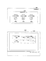
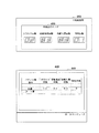
ところで、第3図柄表示装置42(液晶表示装置)には、図5に示すように、左・中・右の3つの装飾図柄列L,M,Rが設定されており、装飾図柄列L,M,R毎に上装飾図柄、中装飾図柄、下装飾図柄の3個ずつの装飾図柄が変動表示される。本実施の形態では、一連の図柄は、「0」〜「9」の数字を各々付した主装飾図柄SZと、菱形状の絵図柄からなる副装飾図柄FZとにより構成されており、数字の昇順又は降順に主装飾図柄SZが表示されると共に各主装飾図柄SZの間に副装飾図柄FZが配されて一連の装飾図柄列L,M,Rが構成されている。そして、周期性を持って主装飾図柄SZと副装飾図柄FZが上から下へと変動表示されるようになっている。   By the way, in the third symbol display device 42 (liquid crystal display device), as shown in FIG. 5, three decorative symbol rows L, M, and R of left, middle, and right are set. For each of M and R, three decorative symbols, an upper decorative symbol, a middle decorative symbol, and a lower decorative symbol, are variably displayed. In the present embodiment, the series of symbols is composed of a main decorative symbol SZ with numbers “0” to “9” and a sub-decorative symbol FZ consisting of rhombus-shaped symbols. A main decorative symbol SZ is displayed in ascending or descending order, and a sub decorative symbol FZ is arranged between the main decorative symbols SZ to form a series of decorative symbol sequences L, M, and R. Then, the main decorative symbol SZ and the sub decorative symbol FZ are displayed in a variably displayed manner from top to bottom with periodicity.

かかる場合、左装飾図柄列Lにおいては、上記一連の装飾図柄が降順(すなわち、主装飾図柄SZの番号が減る順)に表示され、中装飾図柄列M及び右装飾図柄列Rにおいては、同じく上記一連の装飾図柄が昇順(すなわち、主装飾図柄SZの番号が増える順)に表示される。そして、左装飾図柄列L→右装飾図柄列R→中装飾図柄列Mの順に変動表示が停止し、その停止時に第3図柄表示装置42上の5つの有効ライン、すなわち上ラインL1、中ラインL2、下ラインL3、右上がりラインL4、左上がりラインL5の何れかで主装飾図柄SZが大当たり図柄の組合せ(本実施の形態では、同一の主装飾図柄SZの組合せ)で揃えば大当たりとして特別遊技動画が表示されるようになっている。   In this case, in the left decorative design row L, the above-mentioned series of decorative designs are displayed in descending order (that is, in the order of decreasing the number of the main decorative design SZ), and in the middle decorative design row M and the right decorative design row R, the same The series of decorative symbols is displayed in ascending order (that is, in order of increasing the number of the main decorative symbols SZ). Then, the variable display stops in the order of the left decorative symbol row L → the right decorative symbol row R → the middle decorative symbol row M, and at the time of the stop, five effective lines on the third symbol display device 42, that is, the upper line L1, the middle line If the main decorative symbol SZ is a jackpot symbol combination (in this embodiment, the same main decorative symbol SZ combination) in any of L2, the lower line L3, the right rising line L4, and the left rising line L5, it is special as a big hit A game video is displayed.

次に、上記の如く構成されたパチンコ機10の動作について説明する。   Next, the operation of the pachinko machine 10 configured as described above will be described.

本実施の形態では、主制御装置261内のCPU501は、役物作動に係る乱数と、遊技の用に供するその他の乱数とを用いて、第1図柄表示装置40の抽選(大当たり抽選:第1図柄の大当たり抽選)や図柄表示の設定や、第2図柄表示装置41の抽選(第2図柄の当たり抽選)や図柄表示の設定や、第3図柄表示装置42の装飾図柄(第3図柄)の変動表示に関する抽選やその設定を行うこととしている。   In the present embodiment, the CPU 501 in the main control device 261 uses the random number relating to the actuating action and other random numbers used for the game to draw the first symbol display device 40 (lottery lottery: first Symbol jackpot lottery), symbol display settings, lottery drawing of the second symbol display device 41 (second symbol hitting lottery), symbol display settings, and decorative symbols (third symbol) of the third symbol display device 42 A lottery and setting related to variable display will be performed.

具体的には、本実施例のパチンコ機10では、役物作動に係る乱数として、図6に示すように、第1図柄表示装置40の大当たりの抽選に使用する大当たり乱数カウンタC1と、第1図柄表示装置40の大当たり図柄の選択に使用する大当たり図柄カウンタC2と、大当たり乱数カウンタC1の初期値設定に使用する初期値乱数カウンタCINI1と、第2図柄表示装置41の当たりの抽選に使用する第2図柄乱数カウンタC4と、第2図柄乱数カウンタC4の初期値設定に使用する初期値第2図柄乱数カウンタCINI2と、を用いている。   Specifically, in the pachinko machine 10 according to the present embodiment, as shown in FIG. 6, as a random number related to the operation of the accessory, a jackpot random number counter C <b> 1 used for the jackpot lottery of the first symbol display device 40, The jackpot symbol counter C2 used to select the jackpot symbol of the symbol display device 40, the initial value random number counter CINI1 used to set the initial value of the jackpot random number counter C1, and the second symbol used to win the second symbol display device 41. A 2 symbol random number counter C4 and an initial value second symbol random number counter CINI2 used for setting an initial value of the second symbol random number counter C4 are used.

また、このパチンコ機10では、遊技の用に供するその他の乱数として、図6に示すように、第3図柄表示装置42の装飾図柄の変動パターン選択に際して大まかにその変動パターンの種類を特定するための停止パターンの選択に使用する停止パターン選択カウンタC3と、第3図柄表示装置42の装飾図柄の変動パターン選択に使用する変動種別カウンタCS1,CS2,CS3と、第2図柄表示装置41の外れ図柄選択に使用する第2図柄外れ図柄カウンタC5と、を用いている。上述した各カウンタは、CPU501で実行されるプログラムにより構成されている。   Further, in this pachinko machine 10, as other random numbers used for the game, as shown in FIG. 6, when the variation pattern of the decoration symbol of the third symbol display device 42 is selected, the type of the variation pattern is roughly specified. Stop pattern selection counter C3 used for selection of the stop pattern of the symbol, variation type counters CS1, CS2, CS3 used for variation pattern selection of the decorative symbol of the third symbol display device 42, and outlier symbol of the second symbol display device 41 A second off-design symbol counter C5 used for selection is used. Each counter described above is constituted by a program executed by the CPU 501.

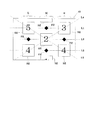
例えば、「停止パターン0」は複数種類の完全外れ変動パターンからなる完全外れ変動パターン群を示すものであり、「停止パターン1」は複数種類の前後外れリーチ変動パターンからなる前後外れリーチ変動パターン群を示すものであり、「停止パターン2」は複数種類の前後外れ以外リーチ変動パターンからなる前後外れ以外リーチ変動パターン群を示すものであり、「停止パターン3」は複数種類の通常大当たり変動パターンからなる通常大当たり変動パターン群を示すものであり、「停止パターン4」は複数種類の確変大当たり変動パターンからなる確変大当たり変動パターン群を示すものである。   For example, “stop pattern 0” indicates a complete deviation variation pattern group including a plurality of types of complete deviation variation patterns, and “stop pattern 1” indicates a front / rear deviation variation pattern group including a plurality of types of front / rear deviation variation patterns. “Stop pattern 2” indicates a reach variation pattern group other than front / rear out of reach variation patterns consisting of a plurality of types of reach variation patterns other than front / rear out, and “Stop pattern 3” indicates a plurality of types of normal jackpot variation patterns. In this case, “stop pattern 4” represents a probability variation jackpot variation pattern group composed of a plurality of types of probability variation jackpot variation patterns.

これら全てのカウンタC1〜C5,CINI1〜CINI2,CS1〜CS3は、その更新の都度、前回値に「1」が加算され(以下、「更新」という)、最大値に達した後「0」に戻るループカウンタとなっている。各カウンタは定期的に更新され、その更新値が図6に示すRAM503の所定領域に設定されたカウンタ用バッファに適宜それぞれ格納される。また、RAM503には、1つの実行エリアと4つの保留エリア(保留第1〜第4エリア)とからなる保留球格納エリアが設けられており、これらの各エリアには、第1の始動口33a,33bへの遊技球の入賞履歴に合わせて、大当たり乱数カウンタC1、大当たり図柄カウンタC2及び停止パターン選択カウンタC3の各値が時系列的に格納されるようになっている。   All of these counters C1 to C5, CINI1 to CINI2, and CS1 to CS3 are incremented by “1” (hereinafter referred to as “update”) every time they are updated, and then set to “0” after reaching the maximum value. It is a return loop counter. Each counter is periodically updated, and the updated value is appropriately stored in a counter buffer set in a predetermined area of the RAM 503 shown in FIG. The RAM 503 is provided with a holding ball storage area including one execution area and four holding areas (holding first to fourth areas). Each of these areas has a first start port 33a. , 33b, the values of the jackpot random number counter C1, the jackpot symbol counter C2, and the stop pattern selection counter C3 are stored in time series in accordance with the winning history of the game balls.

上述した各カウンタについて図6を用いて以下に詳細に説明する。大当たり乱数カウンタC1は、例えば「0」〜「738」の範囲内で順に1ずつ加算され、最大値(つまり「738」)に達した後「0」に戻る構成となっている。特に大当たり乱数カウンタC1が1周した場合、その時点の初期値乱数カウンタCINI1の値が当該大当たり乱数カウンタC1の初期値として読み込まれる。なお、初期値乱数カウンタCINI1は、大当たり乱数カウンタC1と同様のループカウンタであり(値=0〜738)、後述するタイマ割込み(図11参照)毎に1回更新されるとともに、後述する通常処理(図8参照)の残余時間内で繰り返し更新される。大当たり乱数カウンタC1は定期的に(本実施の形態では後述するタイマ割込み(図11参照)毎に1回)更新され、遊技球が第1の始動口33a,33bに入賞したタイミングでRAM503の保留球格納エリアに格納される。   Each counter described above will be described in detail below with reference to FIG. The jackpot random number counter C1 is, for example, incremented by 1 within a range of “0” to “738”, and returns to “0” after reaching the maximum value (ie, “738”). In particular, when the jackpot random number counter C1 makes one round, the value of the initial value random number counter CINI1 at that time is read as the initial value of the jackpot random number counter C1. The initial value random number counter CINI1 is a loop counter similar to the big hit random number counter C1 (value = 0 to 738), and is updated once every timer interrupt (see FIG. 11) described later, and a normal process described later. It is repeatedly updated within the remaining time (see FIG. 8). The jackpot random number counter C1 is periodically updated (once every timer interrupt (see FIG. 11) described later in this embodiment), and the RAM 503 is held at the timing when the game ball wins the first start port 33a, 33b. Stored in the ball storage area.

大当たり乱数カウンタC1の当り値、つまり、大当たりとなる乱数の値の数は、低確率時と高確率時とで2種類設定されており、低確率時に大当たりとなる乱数の値の個数は2個で、その値は「350,700」であり、高確率時に大当たりとなる乱数の値の個数は14個で、その値は 「50,101,160,209,257,310,361,418,480,517,578,635,677,730」である。なお、高確率時とは、例えば予め定められた確率変動図柄によって大当たりになり、付加価値としてその後の大当たり確率がアップした状態、いわゆる「確変」の時をいい、通常時(低確率時)とはそのような確変状態でない時をいう。   The hit value of the jackpot random number counter C1, that is, the number of random number values that are jackpots is set at low probability and high probability, and the number of random number values that are jackpots at low probability is two The value is “350,700”, the number of random numbers that are jackpots at high probability is 14, and the values are “50, 101, 160, 209, 257, 310, 361, 418, 480”. , 517, 578, 635, 677, 730 ". Note that the high probability means, for example, a state where the jackpot is determined by a predetermined probability variation pattern and the subsequent jackpot probability is increased as added value, that is, a so-called “probability change”. Means the time when it is not such a probable state.

大当たり図柄カウンタC2は、大当たりの際における、第1図柄表示装置40(2個のLED40a,40bからなる)の変動停止時の図柄(本実施例では2個のLED40a,40bの変動表示後の最終発光状態)を決定するものである。本実施例では、大当たり図柄カウンタC2は、例えば「0」〜「4」の範囲内で順に1ずつ加算され、最大値(つまり「4」)に達した後「0」に戻る構成となっている。大当たり図柄カウンタC2は、前述の大当たり乱数カウンタC1の場合と同様に、定期的に(後述するタイマ割込み(図11参照)毎に1回)更新され、遊技球が第1の始動口33a,33bに入賞したタイミングでRAM503の保留球格納エリアに格納される。なお、前述の大当たり乱数カウンタC1が当りで、かつ、大当たり図柄カウンタC2の値が「0」,「4」の場合には、第1図柄表示装置40の両方のLED40a,40bが青色発光状態で停止し、低確率時大当たり、いわゆる通常大当り(非特定当り)を示す。また、前述の大当たり乱数カウンタC1が当りで、かつ、大当たり図柄カウンタC2の値が「1」〜「3」の場合には、第1図柄表示装置40の両方のLED40a,40bが赤色発光状態で停止し、高確率時大当たり、いわゆる確変大当り(特定当り)を示す。なお、大当たり乱数カウンタC1が外れの場合には、大当たり図柄カウンタC2の値に関わらず、第1図柄表示装置40の両方のLED40a,40bが互いに異なる色の発光状態で停止し、外れを示す。   The jackpot symbol counter C2 is a symbol when the first symbol display device 40 (comprising two LEDs 40a and 40b) stops changing in the case of a jackpot (in the present embodiment, the final display after the variation display of the two LEDs 40a and 40b). Light emission state). In this embodiment, the jackpot symbol counter C2 is incremented one by one within a range of “0” to “4”, for example, and reaches a maximum value (ie, “4”) and then returns to “0”. Yes. The jackpot symbol counter C2 is updated periodically (once every timer interrupt (see FIG. 11) described later) as in the case of the jackpot random number counter C1 described above, and the game balls are first started 33a, 33b. Is stored in the reserved ball storage area of the RAM 503 at the timing of winning. When the jackpot random number counter C1 is a win and the values of the jackpot symbol counter C2 are “0” and “4”, both LEDs 40a and 40b of the first symbol display device 40 are in a blue light emitting state. Stops and shows a big hit at low probability, a so-called normal big hit (non-specific hit). When the jackpot random number counter C1 is a win and the value of the jackpot symbol counter C2 is "1" to "3", both LEDs 40a and 40b of the first symbol display device 40 are in a red light emitting state. It stops and shows a big hit at high probability, a so-called probable big hit (specific hit). When the jackpot random number counter C1 is off, regardless of the value of the jackpot symbol counter C2, both the LEDs 40a and 40b of the first symbol display device 40 are stopped in the light emission states of different colors to indicate a disconnection.

また、停止パターン選択カウンタC3は、例えば「0」〜「238」の範囲内で順に1ずつ加算され、最大値(つまり238)に達した後「0」に戻る構成となっている。本実施の形態では、停止パターン選択カウンタC3によって、第3図柄表示装置42での装飾図柄のリーチ発生した後最終停止装飾図柄がリーチ装飾図柄の前後に1つだけずれて停止する「前後外れリーチ」と、同じくリーチ発生した後最終停止装飾図柄がリーチ装飾図柄の前後以外で停止する「前後外れ以外リーチ」と、リーチ発生しない「完全外れ」とを抽選することとしている。例えば、C3=0〜201が完全外れに該当し、C3=202〜208が前後外れリーチに該当し、C3=209〜238が前後外れ以外リーチに該当する。なお、停止パターン選択カウンタC3の抽選(リーチの抽通)内容は、パチンコ機10が低確率時であるか高確率であるか、第1図柄表示装置40の変動時間短縮機能が未作動であるか作動であるか、第1図柄の変動開始時の作動保留球数が何個であるか等に応じて各々個別に設定されるものであっても良い。停止パターン選択カウンタC3は、定期的に(後述するタイマ割込み(図11参照)毎に1回)更新され、遊技球が第1の始動口33a,33bに入賞したタイミングでRAM503の保留球格納エリアに格納される。   Further, the stop pattern selection counter C3 is, for example, incremented one by one within a range of “0” to “238”, and returns to “0” after reaching the maximum value (that is, 238). In the present embodiment, the stop pattern selection counter C3 causes the last stop decorative symbol to stop by one shift before and after the reach decorative symbol after the reach of the decorative symbol on the third symbol display device 42 occurs. "Leach other than front-rear detachment" where the final stop decorative symbol stops other than before and after the reach decorative symbol after the reach has occurred, and "completely disengagement" where the reach does not occur. For example, C3 = 0 to 201 corresponds to complete detachment, C3 = 202 to 208 corresponds to anteroposterior reach, and C3 = 209 to 238 corresponds to reach other than anteroposterior detachment. In addition, the lottery (reach lottery) content of the stop pattern selection counter C3 indicates whether the pachinko machine 10 has a low probability or a high probability, or the variable time reduction function of the first symbol display device 40 has not been activated. It may be set individually depending on whether the number is the number of the operation suspending balls at the start of the variation of the first symbol. The stop pattern selection counter C3 is updated periodically (once for each timer interrupt (see FIG. 11) described later), and the reserved ball storage area of the RAM 503 at the timing when the game ball wins the first start port 33a, 33b. Stored in

また、3つの変動種別カウンタCS1〜CS3のうち、変動種別カウンタCS1は、例えば「0〜198」の範囲内で順に1ずつ加算され、最大値(つまり「198」)に達した後「0」に戻る構成となっており、変動種別カウンタCS2は、例えば「0〜240」の範囲内で順に1ずつ加算され、最大値(つまり「240」)に達した後「0」に戻る構成となっており、変動種別カウンタCS3は、例えば「0〜162」の範囲内で順に1ずつ加算され、最大値(つまり「162」)に達した後「0」に戻る構成となっている。以下の説明では、変動種別カウンタCS1を「第1変動種別カウンタ」、変動種別カウンタCS2を「第2変動種別カウンタ」、変動種別カウンタCS3を「第3変動種別カウンタ」とも適宜に呼ぶこととする。   Of the three variation type counters CS1 to CS3, the variation type counter CS1 is incremented one by one in the range of “0 to 198”, for example, and reaches “0” after reaching the maximum value (ie, “198”). For example, the variation type counter CS2 is incremented one by one within a range of “0 to 240”, for example, and reaches a maximum value (that is, “240”) and then returns to “0”. For example, the variation type counter CS3 is sequentially incremented by 1 within a range of “0 to 162”, and reaches a maximum value (that is, “162”) and then returns to “0”. In the following description, the variation type counter CS1 is also referred to as “first variation type counter”, the variation type counter CS2 is also referred to as “second variation type counter”, and the variation type counter CS3 is also referred to as “third variation type counter” as appropriate. .

第1変動種別カウンタCS1によって、いわゆるノーマルリーチ、スーパーリーチ、プレミアムリーチ等のように装飾図柄(第3図柄)のリーチ種別や、完全外れの種別など、大まかな装飾図柄の変動パターン群が決定される。ここでは、例えば、停止パターン選択カウンタC3が「停止パターン1」を示す値(つまり、前後外れリーチ変動パターン群を示す値)のものであったとし、前後外れリーチ変動パターン群の中でも第1変動種別カウンタCS1によってノーマルリーチ群(種類の異なる複数個のノーマルリーチからなる)の変動パターンが決定されたとする。   The first variation type counter CS1 determines a rough decorative pattern variation pattern group, such as a reach type of a decorative symbol (third symbol), such as a normal reach, a super reach, a premium reach, or a completely unacceptable type. . Here, for example, it is assumed that the stop pattern selection counter C3 has a value indicating “stop pattern 1” (that is, a value indicating the front / rear out of reach reach variation pattern group), and the first variation among the front / rear out of reach reach variation pattern group. It is assumed that the variation pattern of the normal reach group (consisting of a plurality of different normal reach types) is determined by the type counter CS1.

続いて、このように第1変動種別カウンタCS1で決定された変動パターン群の中からさらに一の変動パターンが、第2変動種別カウンタCS2によって決定される。ここでは、例えばノーマルリーチ群の中から一の種類のノーマルリーチが第2変動種別カウンタCS2によって決定されたとする。なお、種類の異なる複数個のノーマルリーチとしては、リーチ発生後に最終停止装飾図柄(本実施の形態では例えば中装飾図柄)が停止するまでの経過時間が異なる等の違いを持たせることで実現することが挙げられる。   Subsequently, one more variation pattern is determined by the second variation type counter CS2 from the variation pattern group determined by the first variation type counter CS1 in this way. Here, for example, it is assumed that one type of normal reach from the normal reach group is determined by the second variation type counter CS2. Note that a plurality of different types of normal reach can be realized by giving different differences such as the elapsed time until the final stop decorative symbol (for example, the middle decorative symbol in this embodiment) stops after the occurrence of reach. Is mentioned.

さらに続いて、このように第2変動種別カウンタCS2で決定された一の変動パターンにおいて変動時間加算を何れの時間とするかが、第3変動種別カウンタCS3によって決定される。例えば、この加算時間としては、第3図柄表示装置42での中装飾図柄列の装飾図柄(第3図柄)が滑り停止するなどの場合には、当該中装飾図柄列の装飾図柄が滑りその後に停止表示されるまでの時間である附加時間が挙げられる。このように、変動種別カウンタCS1〜CS3によって、より細かな装飾図柄変動態様を決定することができる。つまり、これらの変動種別カウンタCS1〜CS3を組み合わせることで、変動パターンの多種多様化を容易に実現できる。   Subsequently, the third variation type counter CS3 determines which time the variation time is added in one variation pattern determined by the second variation type counter CS2. For example, as the addition time, when the decorative symbol (third symbol) of the middle decorative symbol row stops on the third symbol display device 42, the decorative symbol of the middle decorative symbol row slips after that. Additional time, which is the time until stop display is given. In this way, the decoration pattern variation mode can be determined more finely by the variation type counters CS1 to CS3. In other words, a variety of variation patterns can be easily realized by combining these variation type counters CS1 to CS3.

なお、第1変動種別カウンタCS1だけで図柄変動態様を決定したり、第1変動種別カウンタCS1と第2変動種別カウンタCS2だけで図柄変動態様を決定したり、第1変動種別カウンタCS1と停止図柄との組み合わせで同じく図柄変動態様を決定したり、第1変動種別カウンタCS1および第2変動種別カウンタCS2と停止図柄との組み合わせで同じく図柄変動態様を決定したりすることも可能である。   Note that the symbol variation mode is determined only by the first variation type counter CS1, the symbol variation mode is determined only by the first variation type counter CS1 and the second variation type counter CS2, or the first variation type counter CS1 and the stop symbol. It is also possible to determine the symbol variation mode in the same manner as described above, or to determine the symbol variation mode in the combination of the first variation type counter CS1 and the second variation type counter CS2 and the stop symbol.

変動種別カウンタCS1〜CS3は、後述する通常処理が1回実行される毎に1回更新され、当該通常処理内の残余時間内でも繰り返し更新される。そして、第1図柄表示装置40による第1図柄の変動開始時における変動パターン決定に際して変動種別カウンタCS1〜CS3のバッファ値が取得される。したがって、図6に示すように、変動種別カウンタCS1〜CS3は、第1図柄表示装置40による第1図柄の変動開始時に取得することとしているので、保留球格納エリアに保存しておく必要はなく、カウンタ用バッファに逐次更新記憶しておくだけでよい。   The variation type counters CS <b> 1 to CS <b> 3 are updated once every time a normal process to be described later is executed once, and are repeatedly updated even within the remaining time in the normal process. Then, the buffer values of the variation type counters CS1 to CS3 are acquired when the variation pattern is determined when the variation of the first symbol is started by the first symbol display device 40. Therefore, as shown in FIG. 6, since the variation type counters CS1 to CS3 are acquired at the start of the first symbol variation by the first symbol display device 40, it is not necessary to store them in the reserved ball storage area. It is only necessary to sequentially update and store the data in the counter buffer.

なお、上述した各カウンタの大きさや範囲は一例にすぎず任意に変更できる。但し、大当たり乱数カウンタC1、停止パターン選択カウンタC3、変動種別カウンタCS1〜CS3の大きさは何れも異なる素数とし、いかなる場合にも同期しない数値としておくのが望ましい。   In addition, the magnitude | size and range of each counter mentioned above are only examples, and can be changed arbitrarily. However, the big hit random number counter C1, the stop pattern selection counter C3, and the variation type counters CS1 to CS3 are all different prime numbers, and it is desirable that they are numerical values that are not synchronized in any case.

また、図6に示すように、第2図柄表示装置41の第2図柄の抽選には、第2図柄乱数カウンタC4が用いられる。第2図柄乱数カウンタC4は、例えば「0」〜「250」の範囲内で順に1ずつ加算され、最大値(つまり250)に達した後「0」に戻るループカウンタとして構成されている。第2図柄乱数カウンタC4は、定期的に(後述するタイマ割込み(図11参照)毎に1回)更新され、遊技球が左右何れかの第2の始動口34を通過した時に取得される。当選することとなる乱数の値の数は149個あり、その範囲は「5〜153」である。   Further, as shown in FIG. 6, the second symbol random number counter C4 is used for the lottery of the second symbol of the second symbol display device 41. The second symbol random number counter C4 is configured, for example, as a loop counter that is incremented by 1 in the range of “0” to “250” and returns to “0” after reaching the maximum value (that is, 250). The second symbol random number counter C4 is updated periodically (once for each timer interruption (see FIG. 11) described later), and is acquired when the game ball passes through the second start port 34 on either the left or right side. The number of random number values to be won is 149, and the range is “5 to 153”.

特に、第2図柄乱数カウンタC4が1周した場合、その時点の初期値第2図柄乱数カウンタCINI2の値が当該第2図柄乱数カウンタC4の初期値として読み込まれる。なお、初期値第2図柄乱数カウンタCINI2は、第2図柄乱数カウンタC4と同様のループカウンタであり(値=0〜250)、後述するタイマ割込み(図11参照)毎に1回更新されるとともに、後述する通常処理(図8参照)の残余時間内で繰り返し更新される。第2図柄乱数カウンタC4は定期的に(本実施の形態では後述するタイマ割込み(図11参照)毎に1回)更新され、遊技球が第2の始動口34を通過したタイミングでRAM503の第2図柄保留格納エリアに格納される。   In particular, when the second symbol random number counter C4 makes one round, the initial value of the second symbol random number counter CINI2 at that time is read as the initial value of the second symbol random number counter C4. The initial value second symbol random number counter CINI2 is a loop counter similar to the second symbol random number counter C4 (value = 0 to 250) and is updated once every timer interrupt (see FIG. 11) described later. These are repeatedly updated within the remaining time of normal processing (see FIG. 8) described later. The second symbol random number counter C4 is updated periodically (once every timer interrupt (see FIG. 11) described later in the present embodiment), and the second time of the game ball passes through the second start port 34, the second of the RAM 503 2 Stored in the symbol hold storage area.

つまり、RAM503には、保留球格納エリアとは別のエリアたる第2図柄保留格納エリアも有しており、1つの第2図柄用の実行エリアと4つの第2図柄用の保留エリア(第2図柄用保留第1〜第4エリア)とからなる第2図柄保留格納エリアが設けられており、これらの各エリアには、第2の始動口34への遊技球の入賞履歴に合わせて、第2図柄乱数カウンタC4の各値が時系列的に格納されるようになっている。   That is, the RAM 503 also has a second symbol holding storage area which is an area different from the holding ball storage area, and includes one execution area for the second symbol and four holding areas for the second symbol (second A second symbol holding storage area comprising symbol holding first to fourth areas) is provided, and in each of these areas, in accordance with the winning history of game balls to the second starting port 34, the second symbol holding storage area is provided. Each value of the 2 symbol random number counter C4 is stored in time series.

また、第2図柄外れ図柄カウンタC5は、後述する図8での通常処理の第2図柄制御処理が1回実行される毎に1回更新され、その値がカウンタ用バッファの第2図柄外れ図柄バッファに更新取得され、第2図柄乱数カウンタC4の第2図柄保留球格納エリアへの記憶の際に、この第2図柄外れ図柄バッファに更新取得された第2図柄外れ図柄カウンタC5も第2図柄保留球格納エリアに記憶される。したがって、図6に示すように、第2図柄乱数カウンタC4の値が落選の場合には、第2図柄保留球格納エリアの第2図柄外れ図柄カウンタC5の値に基づいて、「×」が描かれた表示部41bの点灯表示される。なお、第2図柄外れ図柄カウンタC5を備えず、第2図柄乱数カウンタC4のみに基づいて第2図柄変動表示結果を行うようにしてもよい。つまり、第2図柄乱数カウンタC4が当選なら「○」が描かれた表示部41aを点灯表示し、落選なら「×」が描かれた表示部41bの点灯表示するごとくである。   Further, the second symbol out-of-symbol counter C5 is updated once every time the second symbol control process of the normal process in FIG. 8 described later is executed once, and the value thereof is updated in the second symbol out-of-symbol of the counter buffer. When the second symbol random number counter C4 stores and updates the second symbol random number counter C4 in the second symbol holding ball storage area, the second symbol outlier symbol counter C5 updated and acquired in the second symbol outlier symbol buffer is also the second symbol. Stored in the holding ball storage area. Therefore, as shown in FIG. 6, when the value of the second symbol random number counter C4 is lost, “x” is drawn based on the value of the second symbol off symbol counter C5 in the second symbol holding ball storage area. The displayed display portion 41b is lit up. The second symbol variation display result may be performed based only on the second symbol random number counter C4 without providing the second symbol outlier symbol counter C5. That is, if the second symbol random number counter C4 is won, the display unit 41a on which “O” is drawn is lit up, and if it is lost, the display unit 41b on which “x” is drawn is lit up.

次いで、主制御装置261内のCPU501により実行される各制御処理を図7〜図17のフローチャートを参照しながら説明する。かかるCPU501の処理としては大別して、電源投入に伴い起動されるメイン処理と、定期的に(本実施の形態では2msec周期で)起動されるタイマ割込み処理と、NMI端子(ノンマスカブル端子)への停電信号の入力により起動されるNMI割込み処理とがあり、説明の便宜上ここでは、先ずタイマ割込み処理とNMI割込み処理とを説明し、その後でメイン処理を説明する。   Next, each control process executed by the CPU 501 in the main controller 261 will be described with reference to the flowcharts of FIGS. The processing of the CPU 501 is broadly divided into main processing that is started when the power is turned on, timer interrupt processing that is started periodically (in this embodiment, at a cycle of 2 msec), and power failure to the NMI terminal (non-maskable terminal). There is an NMI interrupt process activated by the input of a signal. For convenience of explanation, the timer interrupt process and the NMI interrupt process are described first, and then the main process is described.

図11は、タイマ割込み処理を示すフローチャートであり、本処理は主制御装置261のCPU501により例えば2msec毎に実行される。   FIG. 11 is a flowchart showing timer interrupt processing. This processing is executed by the CPU 501 of the main control device 261 every 2 msec, for example.

図11において、先ずステップS601では、各種入賞スイッチの読み込み処理を実行する。すなわち、主制御装置261に接続されている各種スイッチ(但し、RAM消去スイッチ323を除く)の状態を読み込むと共に、当該スイッチの状態を判定して検出情報(入賞検知情報)を保存する。   In FIG. 11, first, in step S601, various winning switch reading processes are executed. That is, the state of various switches (except for the RAM erase switch 323) connected to the main controller 261 is read, and the state of the switch is determined and the detection information (winning detection information) is stored.

その後、ステップS602では、初期値乱数カウンタCINI1と初期値第2図柄乱数カウンタCINI2との更新を実行する。具体的には、初期値乱数カウンタCINI1を1インクリメントすると共に、そのカウンタ値が最大値(本実施の形態では「738」)に達した際「0」にクリアし、初期値第2図柄乱数カウンタCINI2を1インクリメントすると共に、そのカウンタ値が最大値(本実施の形態では「250」)に達した後の1インクリメントの際に「0」にクリアする。そして、初期値乱数カウンタCINI1の更新値を、RAM503の該当するバッファ領域に格納する(図6参照)。   Thereafter, in step S602, the initial value random number counter CINI1 and the initial value second symbol random number counter CINI2 are updated. Specifically, the initial value random number counter CINI1 is incremented by 1 and cleared to “0” when the counter value reaches the maximum value (“738” in the present embodiment). While CINI2 is incremented by 1, it is cleared to “0” at the time of increment of 1 after the counter value reaches the maximum value (“250” in this embodiment). Then, the updated value of the initial value random number counter CINI1 is stored in the corresponding buffer area of the RAM 503 (see FIG. 6).

また、図11に示すように、続くステップS603では、大当たり乱数カウンタC1、大当たり図柄カウンタC2及び停止パターン選択カウンタC3の更新を実行する。具体的には、大当たり乱数カウンタC1、大当たり図柄カウンタC2及び停止パターン選択カウンタC3をそれぞれ1インクリメントすると共に、それらのカウンタ値が最大値(本実施の形態ではそれぞれ、「738」,「4」,「250」)に達した後の1インクリメントの際にそれぞれ「0」にクリアする。そして、各カウンタC1〜C3の更新値を、RAM503の該当するバッファ領域に格納する(図6参照)。   Further, as shown in FIG. 11, in the subsequent step S603, the big hit random number counter C1, the big hit symbol counter C2, and the stop pattern selection counter C3 are updated. Specifically, the jackpot random number counter C1, the jackpot symbol counter C2 and the stop pattern selection counter C3 are each incremented by 1 and their counter values are the maximum values (in this embodiment, “738”, “4”, In the case of 1 increment after reaching “250”), each is cleared to “0”. Then, the updated values of the counters C1 to C3 are stored in the corresponding buffer area of the RAM 503 (see FIG. 6).

その後、図11に示すように、ステップS604では、第1の始動口33a,33bへの入賞に伴う始動入賞処理を実行する。この始動入賞処理を図12のフローチャートにより説明すると、ステップS701では、遊技球が第1の始動口33a,33bに入賞したか否かを作動口スイッチの検出情報により判別する。遊技球が第1の始動口33a,33bに入賞したと判別されると、続くステップS702では、第1図柄表示装置40の作動保留球数Nが上限値(本実施の形態では4)未満であるか否かを判別する。第1の始動口33a,33bへの入賞があり、かつ作動保留球数N<4であることを条件にステップS703に進み、作動保留球数Nを1インクリメントする。   After that, as shown in FIG. 11, in step S604, a start winning process is performed in accordance with winning in the first start ports 33a and 33b. This start winning process will be described with reference to the flowchart of FIG. 12. In step S701, whether or not the game ball has won the first start opening 33a, 33b is determined based on the detection information of the operation opening switch. When it is determined that the game ball has won the first start opening 33a, 33b, in the subsequent step S702, the number N of operation reservation balls of the first symbol display device 40 is less than the upper limit value (4 in the present embodiment). It is determined whether or not there is. The process proceeds to step S703 on the condition that there is a winning at the first start ports 33a and 33b and the number N of actuated balls is less than 4, and the number N of actuated balls is incremented by one.

また、続くステップS704では、第1図柄の当落に関わる乱数を取得する。具体的には、前記ステップS603で更新した大当たり乱数カウンタC1、大当たり図柄カウンタC2及び停止パターン選択カウンタC3の各値を、図6に示したRAM503の保留球格納エリアの空き記憶エリアのうちの最初のエリアに格納する。   In subsequent step S704, a random number related to the winning of the first symbol is acquired. Specifically, the values of the jackpot random number counter C1, the jackpot symbol counter C2 and the stop pattern selection counter C3 updated in step S603 are used as the first of the free storage areas in the reserved ball storage area of the RAM 503 shown in FIG. Store in the area.

また、図11に示すように、続くステップS605では、発射制御処理を実行する。具体的には、発射制御処理では、主制御装置261のCPU501は、図4に示すように、発射制御装置312からの発射許可信号S7がONである場合に、発射制御信号S8及び球送り制御信号S9を発射制御装置312に出力し、発射装置229による遊技球発射制御が行われる。このように発射制御処理をした後、CPU501は本タイマ割込処理を一旦終了する。   Further, as shown in FIG. 11, in the subsequent step S605, a firing control process is executed. Specifically, in the launch control process, the CPU 501 of the main control device 261, as shown in FIG. 4, when the launch permission signal S7 from the launch control device 312 is ON, the launch control signal S8 and the ball feed control. The signal S9 is output to the launch control device 312, and the game ball launch control by the launch device 229 is performed. After performing the firing control process in this way, the CPU 501 once ends this timer interrupt process.

図13は、NMI割込み処理を示すフローチャートであり、本処理は、主制御装置261のCPU501により停電の発生等によるパチンコ機10の電源断時に実行される。このNMI割込みにより、電源断時の主制御装置261の状態がRAM503のバックアップエリアに記憶される。   FIG. 13 is a flowchart showing the NMI interrupt process. This process is executed by the CPU 501 of the main controller 261 when the power of the pachinko machine 10 is cut off due to the occurrence of a power failure or the like. By this NMI interruption, the state of the main controller 261 at the time of power-off is stored in the backup area of the RAM 503.

すなわち、停電の発生等によりパチンコ機10の電源が遮断されると、停電信号S1が停電監視回路542から主制御装置261内のCPU501のNMI端子に出力される。すると、CPU501は実行中の制御を中断して図13のNMI割込み処理を開始する。図13のNMI割込み処理は、主制御装置261のROM502に記憶されている。停電信号S1が出力された後所定時間は、主制御装置261の処理が実行可能となるように電源部541から電源供給がなされており、この所定時間内にNMI割込み処理が実行される。   That is, when the power of the pachinko machine 10 is cut off due to the occurrence of a power failure or the like, the power failure signal S1 is output from the power failure monitoring circuit 542 to the NMI terminal of the CPU 501 in the main controller 261. Then, the CPU 501 interrupts the control being executed and starts the NMI interrupt process of FIG. The NMI interrupt process in FIG. 13 is stored in the ROM 502 of the main controller 261. For a predetermined time after the power failure signal S1 is output, power is supplied from the power supply unit 541 so that the processing of the main controller 261 can be executed, and the NMI interrupt processing is executed within the predetermined time.

図13のNMI割込み処理において、ステップS801では、電源断の発生情報をバックアップエリアに設定する。本実施例では、電源断の発生情報のフラグを立ててバックアップエリアに記憶させる。   In the NMI interrupt process of FIG. 13, in step S801, information on occurrence of power interruption is set in the backup area. In this embodiment, a power off occurrence information flag is set and stored in the backup area.

次に、メイン処理について説明する。
図7は、主制御装置261内のCPU501により実行されるメイン処理の一例を示すフローチャートであり、このメイン処理は電源投入時のリセットに伴い起動される。
Next, the main process will be described.
FIG. 7 is a flowchart showing an example of a main process executed by the CPU 501 in the main control device 261. This main process is started upon a reset at power-on.

先ず、ステップS101では、主制御装置261のCPU501は、電源投入に伴う初期設定処理を実行する。具体的には、スタックポインタに予め決められた所定値を設定する。また、ステップS102では、主制御装置261のCPU501は、サブ側の制御装置(サブ制御装置262、払出制御装置311等)が動作可能な状態になるのを待つために例えば1秒程度、ウエイト処理を実行する。続くステップS103では、主制御装置261のCPU501は、RAMアクセスを許可する。   First, in step S101, the CPU 501 of the main control device 261 executes an initial setting process associated with power-on. Specifically, a predetermined value set in advance for the stack pointer is set. In step S102, the CPU 501 of the main control device 261 waits for, for example, about 1 second in order to wait for the sub-side control devices (sub-control device 262, payout control device 311, etc.) to become operable. Execute. In the subsequent step S103, the CPU 501 of the main control device 261 permits RAM access.

その後、CPU501内のRAM503に関してデータバックアップの処理を実行する。つまり、ステップS104では、主制御装置261のCPU501は、電源監視基板261bに設けたRAM消去スイッチ323が押下(ON)されているか否かを判別し、オフであればステップS105に進み、オンであればステップS113に進む。続くステップS105では、主制御装置261のCPU501は、RAM503のバックアップエリアに電源断の発生情報が設定されているか否か(電源断の発生情報のフラグが立っているか否か)を判別する。また、ステップS106では、主制御装置261のCPU501は、RAM判定値を算出し、続くステップS107では、主制御装置261のCPU501は、そのRAM判定値が電源断時に保存したRAM判定値と一致するか否か、すなわちバックアップの有効性を判別する。RAM判定値は、例えばRAM503の作業領域アドレスにおけるチェックサム値である。なお、RAM503の所定のエリアに書き込まれたキーワードが正しく保存されているか否かによりバックアップの有効性を判断することも可能である。   Thereafter, data backup processing is executed for the RAM 503 in the CPU 501. That is, in step S104, the CPU 501 of the main controller 261 determines whether or not the RAM erase switch 323 provided on the power monitoring board 261b is pressed (ON). If there is, the process proceeds to step S113. In the subsequent step S105, the CPU 501 of the main control device 261 determines whether or not power-off occurrence information is set in the backup area of the RAM 503 (whether or not a power-off occurrence information flag is set). In step S106, the CPU 501 of the main control device 261 calculates a RAM determination value. In the subsequent step S107, the CPU 501 of the main control device 261 matches the RAM determination value stored when the power is turned off. Whether the backup is valid. The RAM determination value is a checksum value at a work area address of the RAM 503, for example. Note that it is possible to determine the effectiveness of backup based on whether or not the keywords written in a predetermined area of the RAM 503 are correctly stored.

上述したように、本パチンコ機10では、例えばホールの営業開始時など、電源投入時に初期状態に戻したい場合にはRAM消去スイッチ323を押しながら電源が投入される。従って、RAM消去スイッチ323がONされていれば、RAM503の初期化処理(ステップS113等)に移行する。また、電源断の発生情報が設定されていない場合や、RAM判定値(チェックサム値等)によりバックアップの異常が確認された場合も同様に、使用RAM領域をクリアおよびRAM503の初期化処理(ステップS113等)に移行する。つまり、ステップS113では、主制御装置261のCPU501は、RAM503の使用領域を「0」にクリアし、RAM503の初期化処理を実行する。   As described above, the pachinko machine 10 is turned on while pressing the RAM erase switch 323 when it is desired to return to the initial state when the power is turned on, for example, when the hall starts business. Therefore, if the RAM erase switch 323 is turned on, the process proceeds to the initialization process of the RAM 503 (step S113 and the like). Similarly, when the information on occurrence of power interruption is not set, or when a backup abnormality is confirmed by the RAM determination value (checksum value or the like), the used RAM area is cleared and the initialization process of the RAM 503 (step S113). That is, in step S113, the CPU 501 of the main control device 261 clears the use area of the RAM 503 to “0” and executes the initialization process of the RAM 503.

続くステップS114では、主制御装置261のCPU501は、払出初期化コマンドを送信する。このように、払出初期化コマンドは、主制御装置261が初期化された時に払出制御装置311に出力される。   In subsequent step S114, CPU 501 of main controller 261 transmits a payout initialization command. Thus, the payout initialization command is output to the payout control device 311 when the main control device 261 is initialized.

また、ステップS115では、主制御装置261のCPU501は、電源投入時のコマンドをサブ制御基板262aに送信する。この電源投入時のコマンドは、パチンコ機の機種を判別するためのコマンドを含むものであり、サブ制御基板262aや表示制御装置45などのサブ側で当該コマンド内容に基づいて機種を判別することができるようになっている。   In step S115, the CPU 501 of the main control device 261 transmits a power-on command to the sub control board 262a. This power-on command includes a command for determining the model of the pachinko machine, and it is possible to determine the model based on the contents of the command on the sub side such as the sub control board 262a and the display control device 45. It can be done.

また、ステップS116では、主制御装置261のCPU501は、CTC(Counter/Timer Circuit)の初期設定を実行する。ステップS117では、主制御装置261のCPU501は、割込み許可を設定し、後述する通常処理(図8参照)に移行する。   In step S116, the CPU 501 of the main control device 261 executes initial setting of a CTC (Counter / Timer Circuit). In step S117, the CPU 501 of the main control device 261 sets interrupt permission, and proceeds to normal processing (see FIG. 8) described later.

一方、RAM消去スイッチ323が押されていない場合には、電源断の発生情報が設定されていること、及びRAM判定値(チェックサム値等)が正常であることを条件に、復電時の処理(電源断復旧時の処理)を実行する。つまり、ステップS108では、電源断の発生情報をクリアする。ステップS109では、主制御装置261のCPU501は、払出復帰コマンドを払出制御装置311に送信し、払出制御開始を払出制御装置311に指示する。詳細は後述するが、払出制御装置311は、主制御装置261から払出復帰コマンドを受信すると、復帰し、払出制御を開始する。   On the other hand, if the RAM erase switch 323 has not been pressed, the power-off occurrence information is set, and the RAM judgment value (checksum value, etc.) is normal. Execute the process (process when power is restored). That is, in step S108, the information on occurrence of power interruption is cleared. In step S109, the CPU 501 of the main control device 261 transmits a payout return command to the payout control device 311 and instructs the payout control device 311 to start payout control. As will be described in detail later, when the payout control device 311 receives a payout return command from the main control device 261, the payout control device 311 returns and starts payout control.

ステップS110では、主制御装置261のCPU501は、サブ側の制御装置を電源断時の遊技状態に複帰させるためのコマンドを送信し、ステップS111では、主制御装置261のCPU501は、CTC(Counter/Timer Circuit)の初期設定を実行する。さらに、ステップS112では、割込み許可を設定し、それから後述する通常処理(図8参照)に移行する。例えば、通常処理の途中で電源断が発生したとしても、当該通常処理の最後のステップ(図8に示す「RAMアクセス禁止」のステップ)まで実行してから電源断状態となるので、復電後は通常処理の最初のステップたるステップS201から実行されることになる。   In step S110, the CPU 501 of the main control device 261 transmits a command for causing the sub-side control device to return to the gaming state when the power is cut off. In step S111, the CPU 501 of the main control device 261 receives the CTC (Counter / Timer Circuit) initial settings. Further, in step S112, the interrupt permission is set, and then the process proceeds to a normal process (see FIG. 8) described later. For example, even if the power interruption occurs during the normal processing, the power is turned off after executing the last step of the normal processing (the “RAM access prohibited” step shown in FIG. 8). Is executed from step S201, which is the first step of normal processing.

次に、通常処理の流れを図8のフローチャートを参照しながら説明する。この通常処理では遊技の主要な処理が実行される。その概要として、ステップS201〜S207の処理が4msec周期の定期処理として実行され、その残余時間でステップS210,S211のカウンタ更新処理が実行される構成となっている。   Next, the flow of normal processing will be described with reference to the flowchart of FIG. In this normal process, the main process of the game is executed. As an outline, the processing of steps S201 to S207 is executed as a periodic processing with a period of 4 msec, and the counter update processing of steps S210 and S211 is executed with the remaining time.

図8において、先ずステップS201では、主制御装置261のCPU501は、前回の処理で更新されたコマンド等の出力データをサブ側の各制御装置に送信するという外部出力処理を行う。具体的には、入賞検知情報の有無を判別し、入賞検知情報があれば払出制御装置311に対して獲得遊技球数に対応する賞球払出コマンドを送信する。また、第1図柄表示装置40の第1図柄変動表示(2個のLED40a,40bの変動表示)に連動して第3図柄表示装置42による装飾図柄(第3図柄)の変動表示も行われるのであるが、第1図柄表示装置40の第1図柄の変動表示に際して変動パターン指定コマンド、装飾図柄指定コマンド、全停止コマンド(確定コマンド)等を外部出力処理においてサブ制御装置262に送信する。   In FIG. 8, first, in step S <b> 201, the CPU 501 of the main control device 261 performs an external output process of transmitting output data such as a command updated in the previous process to each control device on the sub side. Specifically, the presence / absence of winning detection information is determined, and if there is winning detection information, a winning ball payout command corresponding to the number of acquired game balls is transmitted to the payout control device 311. In addition, since the first symbol display of the first symbol display device 40 (variation display of the two LEDs 40a and 40b) is linked with the third symbol display device 42, the decorative symbol (third symbol) is also displayed. However, when the first symbol display device 40 displays the variation of the first symbol, a variation pattern designation command, a decoration symbol designation command, an all stop command (confirmation command), etc. are transmitted to the sub-control device 262 in the external output process.

なお、このパチンコ機10では、第1図柄の変動開始時において、変動パターン指定コマンド→演出コマンド(変動時間の変更等を指定するためのコマンド)→装飾図柄指定コマンドの順で通常処理の外部出力処理の都度所定個数(例えば3つ)ずつ(すなわち、4msec毎に3つずつ)コマンドが送出され、変動時間経過のタイミングで全停止コマンドが送出されるようになっている。また、第1図柄の変動開始後において、変動パターン指定コマンド→演出コマンド→装飾図柄指定コマンドの順で通常処理の外部出力処理の都度所定個数(例えば3つ)ずつ(すなわち、4msec毎に3つずつ)コマンドが送出され、変動時間経過のタイミングで全停止コマンドが送出されるようにしてもよい。   In this pachinko machine 10, external output of normal processing in the order of variation pattern designation command → production command (command for designating change of variation time) → decoration symbol designation command at the start of variation of the first symbol Each time a process is performed, commands are sent at a predetermined number (for example, three) (that is, every three for every 4 msec), and a stop command is sent at the timing of the change time. Further, after the first symbol variation starts, a predetermined number (for example, three) each time the external output processing of the normal processing is performed in the order of variation pattern designation command → effect command → decorative symbol designation command (ie, three every 4 msec). Command), and a stop command may be sent at the timing when the fluctuation time elapses.

変動パターン指定コマンドは、第3図柄表示装置42で変動表示される装飾図柄(第3図柄)の変動パターンを指定するためのコマンドである。変動パターン指定コマンドは、主制御装置261からサブ制御装置262に送信され、サブ制御装置262から表示制御装置45に送信される。表示制御装置45は、送信されてきた変動パターン指定コマンドに基づいて、装飾図柄の変動パターンを表示実行するように第3図柄表示装置42を制御する。   The variation pattern designation command is a command for designating a variation pattern of a decorative symbol (third symbol) that is variably displayed on the third symbol display device 42. The variation pattern designation command is transmitted from the main control device 261 to the sub-control device 262, and is transmitted from the sub-control device 262 to the display control device 45. The display control device 45 controls the third symbol display device 42 to display and execute the decorative symbol variation pattern based on the transmitted variation pattern designation command.

装飾図柄指定コマンドは、第3図柄表示装置42での装飾図柄(第3図柄)の変動表示演出が、確変大当り(特定当り)、通常大当り(非特定当り)、外れの何れとなるかを指定するためのコマンドである。装飾図柄指定コマンドは、主制御装置261からサブ制御装置262に送信され、サブ制御装置262から表示制御装置45に送信される。表示制御装置45は、装飾図柄の変動パターンの表示結果を、送信されてきた装飾図柄指定コマンドに応じた結果(確変大当り(特定当り)、通常大当り(非特定当り)あるいは外れ)となるように第3図柄表示装置42を表示制御する。   The decorative symbol designation command designates whether the variation display effect of the decorative symbol (third symbol) on the third symbol display device 42 is a probable big hit (specific hit), a normal big hit (non-specific hit), or off. It is a command to do. The decoration symbol designation command is transmitted from the main control device 261 to the sub-control device 262, and is transmitted from the sub-control device 262 to the display control device 45. The display control device 45 displays the display result of the decorative symbol variation pattern as a result (probability big hit (specific hit), normal big hit (non-specific hit) or off) according to the received decorative symbol designation command. Display control of the 3rd symbol display apparatus 42 is carried out.

全停止コマンドは、第3図柄表示装置42で変動表示される装飾図柄(第3図柄)の変動パターンの停止を指示するためのコマンドである。全停止コマンドは、主制御装置261からサブ制御装置262に送信され、サブ制御装置262から表示制御装置45に送信される。表示制御装置45は、送信されてきた全停止コマンドに基づいて、装飾図柄の変動パターンを停止表示するように第3図柄表示装置42を制御する。   The all stop command is a command for instructing to stop the variation pattern of the decorative symbol (third symbol) displayed in a variable manner on the third symbol display device 42. The all stop command is transmitted from the main control device 261 to the sub control device 262, and is transmitted from the sub control device 262 to the display control device 45. The display control device 45 controls the third symbol display device 42 so as to stop and display the decorative symbol variation pattern based on the transmitted all stop command.

また、主制御装置261のCPU501は、通常処理の外部出力処理(ステップS201)にて、変動パターン指定コマンドと演出コマンド(変動時間の変更等を指定するためのコマンド)とをサブ制御装置262に送信することがある。つまり、変動種別カウンタCS3の値に基づいて変動時間加算(前述した装飾図柄の滑り演出による附加時間)を何れの時間とするかが決定され、このような加算時間を適切にサブ制御装置262に指示するために、演出コマンドが用いられるのである。したがって、第1図柄の変動開始後において、変動パターン指定コマンド→演出コマンド→装飾図柄指定コマンドの順で通常処理の外部出力処理の都度所定個数(例えば3つ)ずつ(すなわち、4msec毎に3つずつ)コマンドが送出され、変動時間経過のタイミングで全停止コマンドが送出されることがある。   In addition, the CPU 501 of the main control device 261 sends a change pattern designation command and an effect command (command for designating change of change time) to the sub-control device 262 in the external output process (step S201) of the normal process. May be sent. That is, based on the value of the variation type counter CS3, it is determined which time the variation time addition (addition time due to the above-described decorative design slip effect) is to be used, and such an addition time is appropriately set in the sub-control device 262. An effect command is used to instruct. Therefore, after the first symbol variation starts, a predetermined number (for example, three) each time the external output processing of the normal processing is performed in the order of variation pattern designation command → effect command → decorative symbol designation command (ie, three every 4 msec). Command), and a stop command may be sent when the fluctuation time has elapsed.

次に、ステップS202では、主制御装置261のCPU501は、変動種別カウンタCS1〜CS3の更新を実行する。具体的には、変動種別カウンタCS1〜CS3をそれぞれ1インクリメントすると共に、それらのカウンタ値が最大値(本実施の形態では198,240,162)に達した後の1インクリメントの際にそれぞれ「0」にクリアする。そして、変動種別カウンタCS1〜CS3の更新値を、RAM503の該当する図6に示すバッファ領域に格納する。   Next, in step S202, the CPU 501 of the main controller 261 updates the variation type counters CS1 to CS3. Specifically, each of the variation type counters CS1 to CS3 is incremented by 1, and each counter value reaches “0” (198, 240, 162 in the present embodiment) and is incremented by “0”. To clear. Then, the update values of the variation type counters CS1 to CS3 are stored in the corresponding buffer area shown in FIG.

続く図8のステップS203では、主制御装置261のCPU501は、払出制御装置311より受信した賞球計数信号や払出異常信号や下皿満タン信号を読み込む。その後、ステップS204では、第1図柄表示装置40による第1図柄の変動表示を行うための第1図柄変動処理を実行する。この第1図柄変動処理により、大当たり判定や第1図柄の変動パターンの設定などが行われる。但し、第1図柄変動処理の詳細は後述する。   In the subsequent step S203 of FIG. 8, the CPU 501 of the main control device 261 reads the prize ball counting signal, the payout abnormality signal, and the lower dish full signal received from the payout control device 311. Thereafter, in step S204, a first symbol variation process for performing variation display of the first symbol by the first symbol display device 40 is executed. By this first symbol variation process, jackpot determination, variation setting of the first symbol, and the like are performed. The details of the first symbol variation process will be described later.

その後、ステップS205では、主制御装置261のCPU501は、大当たり状態である場合において可変入賞装置32の大入賞口32aを開放又は閉鎖するための大入賞口開閉処理を実行する。すなわち、大当たり状態のラウンド毎に大入賞口32aを開放し、そのラウンド毎に、大入賞口32aの最大開放時間が経過したか、又は大入賞口32aに遊技球が規定数だけ入賞したかを判定する。そして、これら何れかの条件が成立するとそのラウンドにおける大入賞口32aの開放を止めて閉鎖し、残りのラウンドがある場合には、大入賞口32aの開放を残りラウンド数繰り返し実行する。   Thereafter, in step S205, the CPU 501 of the main control device 261 executes a big prize opening / closing process for opening or closing the big prize opening 32a of the variable prize winning device 32 in the case of the big hit state. That is, the big winning opening 32a is opened for each round in the big hit state, and whether the maximum opening time of the big winning opening 32a has passed for each round, or whether a predetermined number of game balls have been won in the big winning opening 32a. judge. When any of these conditions is satisfied, the special winning opening 32a is stopped and closed during the round, and when there are remaining rounds, the special winning opening 32a is opened repeatedly for the remaining number of rounds.

また、ステップS206では、主制御装置261のCPU501は、第2図柄表示装置41による第2図柄の表示制御を実行する。簡単に説明すると、遊技球が第2の始動口34を通過したことを条件に、その都度の第2図柄乱数カウンタC4が取得されると共に第2図柄表示装置41の表示部41a,41bにて第2図柄の変動表示が実施される。そして、第2図柄乱数カウンタC4の値により第2図柄の抽選が実施され、第2図柄の当たり状態になると、主制御装置261のCPU501は、ステップS207に示すように、下部側の第1の始動口33bを所定時間開放するという第1の始動口33bの開放処理を行う。なお説明は省略したが、第2図柄乱数カウンタC4も、大当たり乱数カウンタC1、大当たり図柄カウンタC2及び停止パターン選択カウンタC3と同様に、図11に示すタイマ割込処理にて更新されるようになっている。   In step S206, the CPU 501 of the main control device 261 executes display control of the second symbol by the second symbol display device 41. Briefly, on the condition that the game ball has passed through the second starting port 34, the second symbol random number counter C4 is acquired and the display units 41a and 41b of the second symbol display device 41 each time. Variation display of the second symbol is performed. Then, when the second symbol lottery is carried out based on the value of the second symbol random number counter C4 and the second symbol wins, the CPU 501 of the main control device 261, as shown in step S207, displays the first symbol on the lower side. An opening process of the first start port 33b is performed in which the start port 33b is opened for a predetermined time. Although the explanation is omitted, the second symbol random number counter C4 is also updated by the timer interruption process shown in FIG. 11, like the jackpot random number counter C1, the jackpot symbol counter C2, and the stop pattern selection counter C3. ing.

また、ステップS208では、主制御装置261のCPU501は、RAM503のバックアップエリアに電源断の発生情報が設定されているか否か(電源断の発生情報のフラグが立っているか否か)を判別する。電源断の発生情報が設定されていない場合には、ステップS209に進み、電源断の発生情報が設定されている場合には、ステップS212に進む。   In step S208, the CPU 501 of the main control device 261 determines whether or not power-off occurrence information is set in the backup area of the RAM 503 (whether or not a power-off occurrence information flag is set). If the information on occurrence of power interruption is not set, the process proceeds to step S209, and if the occurrence information of power interruption is set, the process proceeds to step S212.

その後、ステップS209では、次の通常処理の実行タイミングに至ったか否か、すなわち前回の通常処理の開始から所定時間(本実施の形態では4msec)が経過したか否かを判別する。そして、次の通常処理の実行タイミングに至るまでの残余時間内において、初期値乱数カウンタCINI1、初期値第2図柄乱数カウンタCINI2及び変動種別カウンタCS1〜CS3の更新を繰り返し実行する(ステップS210,S211)。つまり、ステップS210では、初期値乱数カウンタCINI1及び初期値第2図柄乱数カウンタCINI2の更新を実行する。具体的には、初期値乱数カウンタCINI1を1インクリメントすると共に、そのカウンタ値が最大値(本実施の形態では「738」)に達した後の1インクリメントの際に「0」にクリアする。そして、初期値乱数カウンタCINI1の更新値を、RAM503の該当するバッファ領域に格納する。これと同様に、初期値第2図柄乱数カウンタCINI2を1インクリメントすると共に、そのカウンタ値が最大値(本実施の形態では「250」)に達した後の1インクリメントの際に「0」にクリアする。そして、初期値第2図柄乱数カウンタCINI2の更新値を、RAM503の該当するバッファ領域に格納する。   Thereafter, in step S209, it is determined whether or not the next normal process execution timing has been reached, that is, whether or not a predetermined time (4 msec in the present embodiment) has elapsed since the start of the previous normal process. Then, the update of the initial value random number counter CINI1, the initial value second symbol random number counter CINI2, and the variation type counters CS1 to CS3 is repeatedly executed within the remaining time until the execution timing of the next normal processing (steps S210 and S211). ). That is, in step S210, the initial value random number counter CINI1 and the initial value second symbol random number counter CINI2 are updated. Specifically, the initial value random number counter CINI1 is incremented by 1, and is cleared to “0” at the time of increment of 1 after the counter value reaches the maximum value (“738” in the present embodiment). Then, the updated value of the initial value random number counter CINI1 is stored in the corresponding buffer area of the RAM 503. Similarly, the initial value second symbol random number counter CINI2 is incremented by 1 and cleared to “0” when incremented by 1 after the counter value reaches the maximum value (“250” in the present embodiment). To do. Then, the updated value of the initial value second symbol random number counter CINI2 is stored in the corresponding buffer area of the RAM 503.

また、ステップS211では、変動種別カウンタCS1〜CS3の更新を実行する(前記ステップS202と同様)。具体的には、変動種別カウンタCS1〜CS3を1インクリメントすると共に、それらのカウンタ値が最大値(本実施の形態では「198」,「240」,「162」)に達した後の1インクリメントの際にそれぞれ「0」にクリアする。そして、変動種別カウンタCS1〜CS3の更新値を、RAM503の該当するバッファ領域に格納する。   In step S211, the variation type counters CS1 to CS3 are updated (same as step S202). Specifically, the variation type counters CS1 to CS3 are incremented by 1, and the increment value of the increments after reaching the maximum value (“198”, “240”, “162” in the present embodiment) is increased. Each time it is cleared to "0". Then, the updated values of the variation type counters CS1 to CS3 are stored in the corresponding buffer area of the RAM 503.

ここで、ステップS201〜S207の各処理の実行時間は遊技の状態に応じて変化するため、次の通常処理の実行タイミングに至るまでの残余時間は一定でなく変動する。故に、かかる残余時間を使用して初期値乱数カウンタCINI1,初期値第2図柄乱数カウンタCINI2の更新を繰り返し実行することにより、初期値乱数カウンタCINI1(すなわち、大当たり乱数カウンタC1の初期値)及び初期値第2図柄乱数カウンタCINI2(すなわち、第2図柄乱数カウンタC4の初期値)をランダムに更新することができるようになる。   Here, since the execution time of each process of steps S201 to S207 changes according to the state of the game, the remaining time until the execution timing of the next normal process is not constant and varies. Therefore, by repeatedly executing the initial value random number counter CINI1 and the initial value second symbol random number counter CINI2 using the remaining time, the initial value random number counter CINI1 (that is, the initial value of the big hit random number counter C1) and the initial value The value second symbol random number counter CINI2 (that is, the initial value of the second symbol random number counter C4) can be updated at random.

また、ステップS208において、電源断の発生情報が設定されていて、ステップS212に進んだ場合には、主制御装置261のCPU501は、割込み禁止を設定する。続いて、ステップS213では、主制御装置261のCPU501は、電源が速断されたことを示す電源断通知コマンドを他の制御装置に対して送信する。続いて、ステップS214では、主制御装置261のCPU501は、制御信号の出力を停止する。続いて、ステップS215では、主制御装置261のCPU501は、RAM判定値を算出し、バックアップエリアに保存する。RAM判定値は、例えば、RAM503の作業領域アドレスにおけるチェックサム値である。続いて、ステップS216では、主制御装置261のCPU501は、RAMアクセスを禁止する。その後は、電源が完全に遮断して処理が実行できなくなるのに備え、無限ループに入る。   In step S208, if the information on occurrence of power interruption is set, and the process proceeds to step S212, the CPU 501 of the main control device 261 sets interrupt inhibition. Subsequently, in step S213, the CPU 501 of the main control device 261 transmits a power-off notification command indicating that the power has been quickly turned off to another control device. Subsequently, in step S214, the CPU 501 of the main controller 261 stops outputting the control signal. Subsequently, in step S215, the CPU 501 of the main controller 261 calculates a RAM determination value and stores it in the backup area. The RAM determination value is, for example, a checksum value at the work area address of the RAM 503. Subsequently, in step S216, the CPU 501 of the main controller 261 prohibits RAM access. After that, an infinite loop is entered in preparation for the case where the power supply is completely shut down and processing cannot be executed.

次に、前記ステップS205の第1図柄変動処理を図9のフローチャートを参照して説明する。   Next, the first symbol variation process of step S205 will be described with reference to the flowchart of FIG.

図9において、ステップS401では、主制御装置261のCPU501は、今現在大当たり中であるか否かを判別する。なお、大当たり中には、大当たりの際に第3図柄表示装置42で表示される特別遊技の最中と特別遊技終了後の所定時間の最中とが含まれる。続くステップS402では、主制御装置261のCPU501は、第1図柄表示装置40による第1図柄の変動表示中であるか否かを判別する。そして、大当たり中でなくさらに第1図柄の変動表示中でもない場合、ステップS403に進み、主制御装置261のCPU501は、第1図柄表示装置40の作動保留球数Nが「0」よりも大きいか否かを判別する。このとき、大当たり中であるか、又は作動保留球数Nが「0」である場合、そのまま本処理を終了する。   In FIG. 9, in step S401, the CPU 501 of the main control device 261 determines whether or not it is currently a big hit. The jackpot includes a special game displayed on the third symbol display device 42 and a predetermined time after the special game is ended. In the subsequent step S402, the CPU 501 of the main control device 261 determines whether or not the first symbol display device 40 is currently displaying the variation of the first symbol. If it is not a big hit and the first symbol variation is not being displayed, the process proceeds to step S403, where the CPU 501 of the main control device 261 determines whether the number N of active suspension balls of the first symbol display device 40 is greater than “0”. Determine whether or not. At this time, if it is a big hit or if the number N of active suspension balls is “0”, the present process is terminated as it is.

また、大当たり中、第1図柄の変動表示中の何れでもなく且つ作動保留球数N>0であれば、ステップS404に進む。ステップS404では、主制御装置261のCPU501は、作動保留球数Nを「1」減算する。ステップS405では、保留球格納エリアに格納されたデータをシフトさせる処理を実行する。このデータシフト処理は、保留球格納エリアの保留第1〜第4エリアに格納されているデータを実行エリア側に順にシフトさせる処理であって、保留第1エリア→実行エリア、保留第2エリア→保留第1エリア、保留第3エリア→保留第2ユリア、保留第4エリア→保留第3エリアといった具合に各エリア内のデータがシフトされる。   Further, if it is neither a big hit nor a change display of the first symbol, and if the number of operation hold balls N> 0, the process proceeds to step S404. In step S <b> 404, the CPU 501 of the main control device 261 subtracts “1” from the number N of pending operation balls. In step S405, a process for shifting the data stored in the reserved ball storage area is executed. This data shift process is a process of sequentially shifting the data stored in the reserved first to fourth areas of the reserved ball storage area to the execution area side, and the reserved first area → execution area, reserved second area → The data in each area is shifted, such as the hold first area, the hold third area → the hold second urea, the hold fourth area → the hold third area.

その後、ステップS406では、主制御装置261のCPU501は、変動開始処理を実行する。ここで、図10のフローチャートを用いて変動開始処理を詳細に説明すると、ステップS501では、主制御装置261のCPU501は、保留球格納エリアの実行エリアに格納されている大当たり乱数カウンタC1の値に基づいて大当たりか否かを判別する。具体的には、大当たりか否かは大当たり乱数カウンタC1の値とその時々のモード(確変状態であるのか通常状態であるのか)との関係に基づいて判別され、前述した通り通常の低確率時には大当たり乱数カウンタC1の数値「0」〜「738」のうち「350,700」が当たり値(2個)であり、高確率時には「50,101,160,209,257,310,361,418,480,517,578,635,677,730」が当たり値(14個)である。   Thereafter, in step S406, the CPU 501 of the main control device 261 executes a change start process. Here, the variation start process will be described in detail with reference to the flowchart of FIG. 10. In step S501, the CPU 501 of the main controller 261 sets the value of the jackpot random number counter C1 stored in the execution area of the reserved ball storage area. It is determined whether or not it is a big hit based on. Specifically, whether or not it is a big hit is determined based on the relationship between the value of the big hit random number counter C1 and the mode at that time (whether it is a probabilistic variation state or a normal state). Of the numerical values “0” to “738” of the jackpot random number counter C1, “350,700” is the winning value (two), and “50, 101, 160, 209, 257, 310, 361, 418, "480, 517, 578, 635, 677, 730" is the winning value (14).

主制御装置261のCPU501は、大当たりであると判別した場合、ステップS502では、保留球格納エリアの実行エリアに格納されている大当たり図柄カウンタC2の値に対応する大当たり図柄、すなわち、第1図柄表示装置40の2個のLED40a,40bで表示される、確変大当り(特定当り)としての両LED40a,40bを赤色点灯表示または通常大当り(非特定当り)としての両LED40a,40bを青色点灯表示の何れかとする停止図柄(停止表示)を求める。つまり、大当たり図柄カウンタC2の値と図柄との対応関係を表すテーブル(図示省略)に基づいて、大当たり図柄カウンタC2の値に対応する大当たり図柄(「特定当り図柄」または「非特定当り図柄」)を求める。   If the CPU 501 of the main control device 261 determines that it is a big hit, in step S502, the big hit symbol corresponding to the value of the big hit symbol counter C2 stored in the execution area of the reserved ball storage area, that is, the first symbol display. Either the LED 40a, 40b as a probable big hit (specific hit) displayed on the two LEDs 40a, 40b of the device 40 is displayed in red or the LED 40a, 40b as a normal big hit (non-specific hit) is displayed in blue. Find the stop symbol (stop display). That is, based on a table (not shown) indicating the correspondence between the value of the jackpot symbol counter C2 and the symbol, the jackpot symbol corresponding to the value of the jackpot symbol counter C2 ("specific hit symbol" or "non-specific hit symbol") Ask for.

次に、ステップS503では、主制御装置261のCPU501は、大当たり時における変動パターン(大当たり演出パターン)を決定する。具体的には、主制御装置261のCPU501は、停止パターン選択カウンタC3を用いることなく、RAM503のカウンタ用バッファに格納されている大当たり図柄カウンタC2の値及び変動種別カウンタCS1,CS2の値をその順に確認し、変動パターンを決定する。   Next, in step S503, the CPU 501 of the main control device 261 determines a variation pattern (a jackpot effect pattern) at the time of the jackpot. Specifically, the CPU 501 of the main control device 261 uses the value of the jackpot symbol counter C2 and the values of the variation type counters CS1 and CS2 stored in the counter buffer of the RAM 503 without using the stop pattern selection counter C3. Check in order and determine the variation pattern.

つまり、大当たり図柄カウンタC2の値に基づいて、第3図柄表示装置42での装飾図柄を通常大当り(非特定当り)の「停止パターン3」で表示するのか、又は第3図柄表示装置42での装飾図柄を確変大当り(特定当り)の「停止パターン4」で表示するのかを決定する。このように決定した「停止パターン3」または「停止パターン4」の種別をさらに第1変動種別カウンタCS1の値に基づいて決定する。つまり、ノーマルリーチ、スーパーリーチ、プレミアムリーチ等のように装飾図柄(第3図柄)のリーチ種別など、大まかな装飾図柄の変動パターン群を決定する。続いて、このように決定した大まかな装飾図柄の変動パターン群の中から、第2変動種別カウンタCS2の値に基づいて、一の変動パターンを決定する。例えば、第2変動種別カウンタCS2の値に基づいて、リーチ発生後に最終停止装飾図柄(本実施の形態では中装飾図柄)が停止するまでの経過時間を所定時間にする等、より細かな装飾図柄変動態様を決定する。なお、大当たりの場合における次の各関係、つまり、大当たり図柄カウンタC2の数値と停止パターンとの関係、第1変動種別カウンタCS1の数値と変動パターンとの関係、第2変動種別カウンタCS2の数値と停止図柄時間との関係は、それぞれに大当たり用のテーブル等により予め規定されている。   That is, based on the value of the jackpot symbol counter C2, whether the decorative symbol on the third symbol display device 42 is displayed as the “stop pattern 3” of the normal jackpot (non-specific hit), or on the third symbol display device 42 It is determined whether or not the decorative symbol is displayed with “stop pattern 4” of the probable big hit (specific hit). The type of “stop pattern 3” or “stop pattern 4” thus determined is further determined based on the value of the first variation type counter CS1. That is, a rough decorative pattern variation pattern group such as a reach type of a decorative symbol (third symbol) such as normal reach, super reach, premium reach, or the like is determined. Subsequently, one variation pattern is determined based on the value of the second variation type counter CS2 from the group of variation patterns of the rough decorative design determined as described above. For example, based on the value of the second variation type counter CS2, a finer decorative pattern such as a predetermined time is set for the elapsed time until the final stop decorative pattern (in this embodiment, the middle decorative pattern) stops after the reach occurs. The variation mode is determined. The following relations in the case of jackpot, that is, the relation between the numerical value of the jackpot symbol counter C2 and the stop pattern, the relation between the numerical value of the first fluctuation type counter CS1 and the fluctuation pattern, the numerical value of the second fluctuation type counter CS2 The relationship with the stop symbol time is defined in advance by a jackpot table or the like.

一方、ステップS501で大当たりではないと判別された場合には、ステップS504において、主制御装置261のCPU501は、外れ図柄、すなわち第1図柄表示装置40の2個のLED40a,40bにて色違いで停止表示させるという停止図柄に設定する。   On the other hand, if it is determined in step S501 that the game is not a big hit, in step S504, the CPU 501 of the main control device 261 uses different colors in the two symbols 40a and 40b of the out symbol, that is, the first symbol display device 40. Set the stop symbol to stop display.

次に、ステップS505では、主制御装置261のCPU501は、外れ時における変動パターン(外れ演出パターン)を決定し、当該外れ変動パターンを変動パターン指定コマンドに設定する。具体的には、主制御装置261のCPU501は、RAM503の保留球格納エリアの実行エリアに格納されている停止パターン選択カウンタC3及び変動種別カウンタCS1,CS2の値をその順に確認し、変動パターンを決定する。   Next, in step S505, the CPU 501 of the main control device 261 determines a fluctuation pattern (outage effect pattern) at the time of deviation, and sets the deviation fluctuation pattern as a fluctuation pattern designation command. Specifically, the CPU 501 of the main controller 261 checks the values of the stop pattern selection counter C3 and the variation type counters CS1 and CS2 stored in the execution area of the reserved ball storage area of the RAM 503 in that order, and displays the variation pattern. decide.

つまり、停止パターン選択カウンタC3の値に基づいて、第3図柄表示装置42での装飾図柄のリーチ発生した後最終停止装飾図柄がリーチ装飾図柄の前後に1つだけずれて停止する「前後外れリーチ」である「停止パターン1」と、同じくリーチ発生した後最終停止装飾図柄がリーチ装飾図柄の前後以外で停止する「前後外れ以外リーチ」である「停止パターン2」と、リーチ発生しない「完全外れ」である「停止パターン0」との何れの停止パターンにするかを決定する。例えば、この決定した停止パターンが例えば前後外れリーチとなる「停止パターン1」である場合には、第1変動種別カウンタCS1の値に基づいて、前後外れリーチ変動パターン群の中からノーマルリーチ、スーパーリーチ等のような装飾図柄(第3図柄)のリーチ種別が特定された変動パターンが決定されるなど、大まかな装飾図柄の変動パターン群を決定する。なおここではノーマルリーチが決定されたとする。続いて、このように決定した大まかな装飾図柄のノーマルリーチ変動パターン群の中から、第2変動種別カウンタCS2の値に基づいて、さらに一の変動パターンを決定する。例えば、第2変動種別カウンタCS2の値に基づいて、リーチ発生後に最終停止装飾図柄(本実施の形態では中装飾図柄)が停止するまでの経過時間を所定時間にする等、より細かな装飾図柄変動態様を決定する。なお、外れの場合における次の各関係、つまり、停止パターン選択カウンタC3の数値と停止パターンとの関係、第1変動種別カウンタCS1の数値と変動パターンとの関係、第2変動種別カウンタCS2の数値と停止図柄時間との関係は、それぞれに外れ用のテーブル等により予め規定されている。   That is, based on the value of the stop pattern selection counter C3, after the reach of the decorative symbol on the third symbol display device 42 occurs, the final stop decorative symbol is shifted by one before and after the reach decorative symbol and stops. "Stop pattern 1", which is the same as the "stop pattern 2", which is the "reach other than front-rear disengagement" where the final stop decorative pattern stops other than before and after the reach decorative pattern, "Stop pattern 0" which is "" is determined. For example, when the determined stop pattern is “stop pattern 1” that is, for example, a front / rear out of reach reach, normal reach, super reach from the front / rear out of reach reach variation pattern group based on the value of the first variation type counter CS1. A variation pattern group of rough decorative symbols is determined, for example, a variation pattern in which the reach type of the decorative symbol (third symbol) such as is specified is determined. Here, it is assumed that normal reach is determined. Subsequently, one variation pattern is further determined based on the value of the second variation type counter CS2 from the normal reach variation pattern group of the rough decorative design determined as described above. For example, based on the value of the second variation type counter CS2, a finer decorative pattern such as a predetermined time is set for the elapsed time until the final stop decorative pattern (in this embodiment, the middle decorative pattern) stops after the reach occurs. The variation mode is determined. It should be noted that the following relationships in the case of deviation, that is, the relationship between the numerical value of the stop pattern selection counter C3 and the stop pattern, the relationship between the numerical value of the first variation type counter CS1 and the variation pattern, and the numerical value of the second variation type counter CS2 And the stop symbol time are defined in advance by a table for detachment.

本実施の形態では、上述の外れ用のテーブルのうちの一つとしては、例えば、低確率時で、第1図柄表示装置40の変動時間短縮機能の状態で、第1図柄の変動開始時の当該第1図柄の作動保留数が「0」の場合に採用されるものがあり、停止パターン選択カウンタC3の値が「0〜201」の場合にはリーチなし(完全外れ)に該当し、「202〜208」が前後外れリーチに該当し、「209〜238」が前後外れ以外リーチに該当するものが挙げられる。   In the present embodiment, as one of the above-mentioned tables for detachment, for example, at the time of low probability, in the state of the variable time shortening function of the first symbol display device 40, when the first symbol variation starts. Some are used when the number of pending operations of the first symbol is “0”. When the value of the stop pattern selection counter C3 is “0 to 201”, it corresponds to no reach (completely missed), and “ 202-208 "corresponds to the front / rear reach, and" 209-238 "corresponds to the reach other than the front / rear reach.

続いて、ステップS506では、主制御装置261のCPU501は、演出時間加算の決定、つまり、ステップS503で決定された大当たり変動パターンまたはステップS505で決定された外れ変動パターンの演出時間の加算の決定を行う。より具体的には、変動種別カウンタCS3の値に基づいて、第3図柄表示装置42での中装飾図柄列の装飾図柄(第3図柄)が滑り停止するなどによる演出時間の増加(当該中装飾図柄列の装飾図柄が滑りそれが停止表示されるまでの時間の増加)を含む変動パターンが決定される。   Subsequently, in step S506, the CPU 501 of the main control device 261 determines the effect time addition, that is, the effect of adding the effect time of the jackpot variation pattern determined in step S503 or the off-variation pattern determined in step S505. Do. More specifically, on the basis of the value of the variation type counter CS3, an increase in the production time due to the sliding stop of the decorative symbol (third symbol) of the middle decorative symbol sequence on the third symbol display device 42 (the middle ornament) A variation pattern including an increase in time until the decorative symbol of the symbol row slides and is stopped and displayed is determined.

また、ステップS507では、主制御装置261のCPU501は、ステップS503で決定された大当たり変動パターンに対応する変動パターン指定コマンド、または、ステップS505で決定された外れ変動パターンに対応する変動パターン指定コマンドを設定する。   In step S507, the CPU 501 of the main controller 261 receives a variation pattern designation command corresponding to the jackpot variation pattern determined in step S503 or a variation pattern designation command corresponding to the outlier variation pattern determined in step S505. Set.

続いて、ステップS508では、主制御装置261のCPU501は、ステップS502,S503を経てきた場合には、ステップS502で決定された第1図柄表示装置40の大当たり図柄(「特定当り図柄」または「非特定当り図柄」)に対応する装飾図柄指定コマンドを設定し、ステップS504,S505を経てきた場合には、ステップS504で決定された第1図柄表示装置40の外れ図柄に対応する装飾図柄指定コマンドを設定する。   Subsequently, in step S508, when the CPU 501 of the main control device 261 has passed through steps S502 and S503, the jackpot symbol (“specific hit symbol” or “non-specific symbol” of the first symbol display device 40 determined in step S502 is determined. If the decorative symbol designation command corresponding to “specific symbol” is set and steps S504 and S505 are performed, the decorative symbol designation command corresponding to the out symbol of the first symbol display device 40 determined in step S504 is set. Set.

続いて、ステップS509では、主制御装置261のCPU501は、ステップS506で決定された演出時間加算に対応する演出時間加算指定コマンドを設定し、本処理を終了する。   Subsequently, in step S509, the CPU 501 of the main control device 261 sets an effect time addition designation command corresponding to the effect time addition determined in step S506, and ends this process.

図9の説明に戻り、ステップS402がYES、すなわち第1図柄の変動表示中である場合には、ステップS407に進み、主制御装置261のCPU501は、第1図柄の変動時間が経過したか否かを判別する。この第1図柄の変動時間は、図10を用いて前述したように決定された変動パターン及び演出時間加算に基づいて決められており、つまり、第1図柄の変動パターンに応じて当該第1図柄の変動時間が決められており、この変動時間が経過した時にステップS407が肯定判別される。変動時間が経過していなければステップS408に進み、変動時間が経過していればステップS409に進む。   Returning to the description of FIG. 9, when step S402 is YES, that is, when the first symbol variation display is being performed, the process proceeds to step S407, and the CPU 501 of the main control device 261 determines whether or not the first symbol variation time has elapsed. Is determined. The variation time of the first symbol is determined based on the variation pattern and the effect time addition determined as described above with reference to FIG. 10, that is, the first symbol according to the variation pattern of the first symbol. The variation time is determined, and when this variation time has elapsed, an affirmative determination is made in step S407. If the variation time has not elapsed, the process proceeds to step S408, and if the variation time has elapsed, the process proceeds to step S409.

そして、ステップS408では、主制御装置261のCPU501は、第1図柄表示装置40での第1図柄の変動表示を更新する。つまり、第1図柄表示装置40の2個のLED40a,40bの変動表示を継続し、本処理を終了する。   In step S408, the CPU 501 of the main control device 261 updates the first symbol variation display on the first symbol display device 40. That is, the variable display of the two LEDs 40a and 40b of the first symbol display device 40 is continued, and this process is terminated.

一方、ステップS409では、主制御装置261のCPU501は、第1図柄の変動表示を停止し、第1図柄の停止図柄を表示図柄へ設定する。つまり、図10のステップS502で大当たり図柄(確変大当り)に決定された場合には、第1図柄表示装置40の2個のLED40a,40bの変動表示後に、この両LED40a,40bを赤色点灯表示し、確変大当り(特定当り)を示し、図10のステップS502で大当たり図柄(通常大当り)に決定された場合には、第1図柄表示装置40の2個のLED40a,40bの変動表示後に、この両LED40a,40bを青色点灯表示し、通常大当り(非特定当り)を示し、図10のステップS504で外れ図柄に決定された場合には、第1図柄表示装置40の2個のLED40a,40bの変動表示後に、この両LED40a,40bを色違いで点灯表示し、外れを示す。   On the other hand, in step S409, the CPU 501 of the main control device 261 stops the first symbol variation display and sets the first symbol stop symbol to the display symbol. In other words, when the big win symbol (probable big hit) is determined in step S502 of FIG. 10, after the two LEDs 40a and 40b of the first symbol display device 40 are displayed in a variable manner, both the LEDs 40a and 40b are displayed in red. 10 shows a probable big hit (specific hit), and when the big win symbol (normal big hit) is determined in step S502 of FIG. 10, both of these two LEDs 40a, 40b of the first symbol display device 40 are displayed after the fluctuation display. When the LEDs 40a and 40b are lit blue and indicate a normal big hit (non-specific hit) and are determined to be out of place in step S504 of FIG. 10, the fluctuations of the two LEDs 40a and 40b of the first symbol display device 40 are changed. After the display, both the LEDs 40a and 40b are lit in different colors to indicate a disconnection.

続いて、ステップS410では、主制御装置261のCPU501は、第3図柄表示装置42で変動表示される装飾図柄(第3図柄)の変動パターンの停止を指示するための全停止コマンドを設定し、その後本処理を終了する。   Subsequently, in step S410, the CPU 501 of the main control device 261 sets an all stop command for instructing to stop the variation pattern of the decorative symbol (third symbol) that is variably displayed on the third symbol display device 42, Thereafter, this process is terminated.

次に、払出制御装置311内のCPU511により実行される払出制御について説明する。図14は、払出制御装置311のメイン処理を示すフローチャートであり、このメイン処理は電源投入時のリセットに伴い起動される。   Next, payout control executed by the CPU 511 in the payout control device 311 will be described. FIG. 14 is a flowchart showing the main process of the payout control apparatus 311. This main process is started upon reset when the power is turned on.

先ず、ステップS901では、電源投入に伴う初期設定処理を実行する。具体的には、払出制御装置311のCPU511は、スタックアドレスと割込みモードを設定する。また、ステップS902では、払出制御装置311のCPU511はRAMアクセスを許可し、ステップS903では、払出制御装置311のCPU511は外部割込みベクタの設定を行う。   First, in step S901, an initial setting process associated with power-on is executed. Specifically, the CPU 511 of the payout control device 311 sets a stack address and an interrupt mode. In step S902, the CPU 511 of the payout control device 311 permits RAM access, and in step S903, the CPU 511 of the payout control device 311 sets an external interrupt vector.

その後、ステップS904では、払出制御装置311のCPU511は、RAM513のバックアップエリアに電源断の発生情報が設定されているか否かを判別する。また、ステップS905では、払出制御装置311のCPU511は、RAM判定値を算出し、続くステップS906では、そのRAM判定値が電源断時に保存したRAM判定値と一致するか否か、すなわちバックアップの有効性を判別する。RAM判定値は、例えばRAM513の作業領域アドレスにおけるチェックサム値である。なお、RAM513の所定のエリアに書き込まれたキーワードが正しく保存されているか否かによりバックアップの有効性を判断することも可能である。   Thereafter, in step S <b> 904, the CPU 511 of the payout control device 311 determines whether power-off occurrence information is set in the backup area of the RAM 513. In step S905, the CPU 511 of the payout control device 311 calculates a RAM determination value, and in the subsequent step S906, whether or not the RAM determination value matches the RAM determination value stored when the power is turned off, that is, the backup is valid. Determine gender. The RAM determination value is, for example, a checksum value at a work area address in the RAM 513. Note that it is possible to determine the effectiveness of backup based on whether or not the keywords written in a predetermined area of the RAM 513 are correctly stored.

続いて、ステップS907では、払出制御装置311のCPU511は、復電時のRAM513の初期設定を行う。具体的には、主制御装置261が初期化されるとこの主制御装置261から払出初期化コマンドが払出制御装置311に送信され、払出制御装置311のCPU511は、主制御装置261からの払出初期化コマンドを受けると、このステップS907で復電時のRAM513の初期設定を行う。つまり、RAM領域の初期化を行い、遊技球の払出しの制御を開始する。   Subsequently, in step S907, the CPU 511 of the payout control device 311 performs initial setting of the RAM 513 at the time of power recovery. Specifically, when the main control device 261 is initialized, a payout initialization command is transmitted from the main control device 261 to the payout control device 311, and the CPU 511 of the payout control device 311 starts payout from the main control device 261. When the reset command is received, initialization of the RAM 513 at the time of power recovery is performed in step S907. That is, the RAM area is initialized, and the control of game ball payout is started.

したがって、電源投入時にRAM消去スイッチ323が押下(ON)されている場合には、主制御装置261が初期化されるとともに、この主制御装置261から払出制御装置311に払出初期化コマンドが送信されることになり、払出制御装置311のCPU511は、主制御装置261からの払出初期化コマンドに基づいて、RAM513の初期化処理が行われる。   Therefore, when the RAM erase switch 323 is pressed (ON) when the power is turned on, the main controller 261 is initialized and a payout initialization command is transmitted from the main controller 261 to the payout controller 311. Accordingly, the CPU 511 of the payout control device 311 performs initialization processing of the RAM 513 based on the payout initialization command from the main control device 261.

続いて、ステップS908では、払出制御装置311のCPU511は、当該CPU511の周辺デバイスの初期設定を行う。具体的には、CPU周辺デバイスとは、CTC(Counter/Timer Circuit)と呼ばれるタイマ制御デバイスであり、このCTCを所定値に設定してタイマ割込みを2ミリ秒(ms)毎に発生させる。   Subsequently, in step S908, the CPU 511 of the payout control device 311 performs initial setting of peripheral devices of the CPU 511. Specifically, the CPU peripheral device is a timer control device called a CTC (Counter / Timer Circuit). This CTC is set to a predetermined value and a timer interrupt is generated every 2 milliseconds (ms).

続いて、ステップS909では、払出制御装置311のCPU511は、割込み許可設定し、後述する払出制御処理に移行する。   Subsequently, in step S909, the CPU 511 of the payout control apparatus 311 sets an interrupt permission, and proceeds to a payout control process described later.

一方、ステップS904にて電源断の発生情報が設定されていない場合や、ステップS906にてRAM判定値(チェックサム値等)によりバックアップの異常が確認された場合も同様に、払出制御装置311のCPU511はRAM513の全領域を「0」にクリア(ステップS910)し、初期化処理を行う(ステップS911)。   On the other hand, when the occurrence information of the power cut-off is not set in step S904 or when a backup abnormality is confirmed by the RAM determination value (checksum value or the like) in step S906, the payout control device 311 also The CPU 511 clears the entire area of the RAM 513 to “0” (step S910), and performs initialization processing (step S911).

次に、払出制御処理の流れを図15のフローチャートを参照しながら説明する。   Next, the flow of the payout control process will be described with reference to the flowchart of FIG.

図15において、ステップS1001では、払出制御装置311のCPU511は、主制御装置261からのコマンドを取得し記憶する。ここで、この記憶するコマンドとしては、15種類の賞球コマンド(1個〜15個の払出しを指示するための15種類の賞球コマンド)や、払出制御装置311への払出制御開始を指示するための払出復帰コマンドや、払出制御装置311への払出初期化を指示するための払出初期化コマンドの合わせて17種類のコマンドが挙げられる。   In FIG. 15, in step S <b> 1001, the CPU 511 of the payout control device 311 acquires and stores a command from the main control device 261. Here, as the commands to be stored, 15 types of prize ball commands (15 types of prize ball commands for instructing 1 to 15 payouts) and the start of payout control to the payout control device 311 are instructed. There are 17 types of commands including a payout return command for payout and a payout initialization command for instructing payout initialization to the payout control device 311.

ステップS1002では、払出制御装置311のCPU511は、払出許可を受信済みか否かを判別する。つまり、払出復帰コマンドや賞球コマンドを受けたか否かを判別する。また、ステップS1003では、払出制御装置311のCPU511は、状態復帰スイッチ(図示省略)をチェックして、状態復帰動作開始と判定した場合に状態復帰動作を実行する。   In step S1002, the CPU 511 of the payout control device 311 determines whether or not the payout permission has been received. That is, it is determined whether or not a payout return command or a prize ball command is received. In step S1003, the CPU 511 of the payout control device 311 checks the state return switch (not shown) and executes the state return operation when it is determined that the state return operation is started.

その後、ステップS1004では、払出制御装置311のCPU511は、下皿15の状態の変化に応じて下皿満タン状態又は下皿満タン解除状態の設定を実行する。すなわち、下皿満タンスイッチの検出信号により下皿15の満タン状態を判別し、下皿満タンになった時、下皿満タン状態の設定を実行し、下皿満タンでなくなった時、下皿満タン解除状態の設定を実行する。   Thereafter, in step S <b> 1004, the CPU 511 of the payout control device 311 executes setting of the lower pan full tank state or the lower pan full tank release state according to the change in the state of the lower pan 15. That is, when the lower pan 15 is detected based on the detection signal of the lower pan full switch, when the lower pan is full, the lower pan full state is set, and when the lower pan full is not reached , Set the lower pan full release state.

また、ステップS1005では、払出制御装置311のCPU511は、タンク球の状態の変化に応じてタンク球無し状態又はタンク球無し解除状態の設定を実行する。すなわち、タンク球無しスイッチの検出信号によりタンク球無し状態を判別し、タンク球無しになった時、タンク球無し状態の設定を実行し、タンク球無しでなくなった時、タンク球無し解除状態の設定を実行する。   In step S1005, the CPU 511 of the payout control device 311 executes setting of a tank ball absence state or a tank ball absence release state according to a change in the state of the tank ball. In other words, the tank ball no switch state is determined based on the detection signal of the tank ball no switch, and when there is no tank ball, the setting of the tank ball no state is executed. Perform configuration.

その後、ステップS1006では、払出制御装置311のCPU511は、報知する状態の有無を判別し、報知する状態が有る場合には払出制御装置311に設けた7セグメントLEDにより報知する。   Thereafter, in step S1006, the CPU 511 of the payout control device 311 determines the presence / absence of a notification state, and notifies the 7-segment LED provided in the payout control device 311 if there is a notification state.

ステップS1007〜S1009では、賞球払出の処理を実行する。この場合、賞球の払出不可状態でなく、且つ前記ステップS1001で記憶した総賞球個数が「0」でなければ(ステップS1007,S1008が共にNO)、ステップS1009に進み、賞球制御処理(後述する図16)を開始する。また、賞球の払出不可状態、又は総賞球個数が0であれば(ステップS1007,S1008の何れかがYES)、貸球払出の処理に移行する。   In steps S1007 to S1009, prize ball payout processing is executed. In this case, if the prize ball is not paid out and the total number of prize balls stored in step S1001 is not “0” (both NO in steps S1007 and S1008), the process proceeds to step S1009 and a prize ball control process ( FIG. 16 described later is started. Further, if the prize ball cannot be paid out or the total number of prize balls is 0 (YES in any of steps S1007 and S1008), the process proceeds to a lending payout process.

その後、ステップS1010〜S1012では、貸球払出の処理を実行する。この場合、貸球の払出不可状態でなく、且つカードユニットからの貸球払出要求を受信していれば(ステップS1010がNO、S1011がYES)、ステップS1012に進み、貸球制御処理(後述する図17)を開始する。また、貸球の払出不可状態、又は貸球払出要求を受信していなければ(ステップS1010がYES又はS1011がNO)、後続のバイブモータ制御(ステップS1013)を実行する。   Thereafter, in steps S1010 to S1012, a rental ball payout process is executed. In this case, if it is not possible to pay out the rent and if a rent-out request from the card unit has been received (NO in step S1010, YES in S1011), the process proceeds to step S1012 and a renting control process (described later). FIG. 17) is started. Further, if a rental ball cannot be paid out or a rental ball payout request has not been received (YES in step S1010 or NO in S1011), subsequent vibrator motor control (step S1013) is executed.

ステップS1013では、払出制御装置311のCPU511は、バイブレータ360(図3参照)の制御(バイブモータ制御)を実行する。その後、ステップS1014では、払出制御装置311のCPU511は、停電発生か否かを判別する。停電発生であればステップS1015に進み、そうでなければステップS1001に戻る。ステップS1015では、払出制御装置311のCPU511は、電源断の発生情報を設定し、ステップS1016では、RAM判定値を作成する。その後は、電源が完全に遮断して処理が実行できなくなるのに備え、無限ループに入る。   In step S1013, the CPU 511 of the payout control device 311 executes control (vibration motor control) of the vibrator 360 (see FIG. 3). Thereafter, in step S1014, the CPU 511 of the payout control device 311 determines whether or not a power failure has occurred. If a power failure has occurred, the process proceeds to step S1015; otherwise, the process returns to step S1001. In step S1015, the CPU 511 of the payout control device 311 sets information on occurrence of power interruption, and creates a RAM determination value in step S1016. After that, an infinite loop is entered in preparation for the case where the power supply is completely shut down and processing cannot be executed.

ここで、図16に示す賞球制御処理において、ステップS1101では、払出モータ358aを駆動させて賞球の払出を実行する。続くステップS1102では、払出モータ358aの回転が正常であるかを払出回転センサの検出結果により判別する。払出モータ358aの回転が正常でなければ、ステップS1103に進み、払出モータ358aを駆動させてリトライ処理を実行すると共に払出モータ358aの停止処理を実行し、その後、図15の払出制御処理に戻る。   Here, in the prize ball control process shown in FIG. 16, in step S1101, the payout motor 358a is driven to execute the prize ball payout. In subsequent step S1102, whether the rotation of the dispensing motor 358a is normal is determined based on the detection result of the dispensing rotation sensor. If the rotation of the payout motor 358a is not normal, the process advances to step S1103 to drive the payout motor 358a to execute a retry process and execute a stop process of the payout motor 358a, and then return to the payout control process in FIG.

また、払出モータ358aの回転が正常であれば、ステップS1104に進み、遊技球のカウントが正常に行われているか否かを払出カウントスイッチの検出結果により判別する。遊技球のカウントが正常でなければ、ステップS1105に進み、払出モータ358aを駆動させてリトライ処理を実行すると共に払出モータ358aの停止処理を実行し、その後、図15の払出制御処理に戻る。   If the rotation of the payout motor 358a is normal, the process proceeds to step S1104, and whether or not the game ball is normally counted is determined based on the detection result of the payout count switch. If the game ball count is not normal, the process advances to step S1105 to drive the payout motor 358a to execute a retry process and execute a stop process of the payout motor 358a, and then returns to the payout control process of FIG.

さらに、遊技球のカウントが正常であれば、ステップS1106に進み、払出カウントスイッチによる遊技球のカウント数が総賞球個数に達して払出が完了したか否かを判別する。払出が完了していれば、ステップS1107で払出モータ358aの停止処理を実行し、その後、図15の払出制御処理に戻る。   Further, if the game ball count is normal, the process proceeds to step S1106, and it is determined whether or not the game ball count by the payout count switch has reached the total number of prize balls and the payout has been completed. If the payout has been completed, a stop process of the payout motor 358a is executed in step S1107, and then the process returns to the payout control process of FIG.

また、図17に示す貸球制御処理において、ステップS1201では、払出モータ358aを駆動させて貸球の払出を実行する。続くステップS1202では、払出モータ358aの回転が正常であるかを払出回転センサの検出結果により判別する。払出モータ358aの回転が正常でなければ、ステップS1203に進み、払出モータ358aを駆動させてリトライ処理を実行すると共に払出モータ358aの停止処理を実行し、その後、図15の払出制御処理に戻る。   In the ball lending control process shown in FIG. 17, in step S1201, the payout motor 358a is driven to pay out a lending ball. In the subsequent step S1202, it is determined from the detection result of the dispensing rotation sensor whether the rotation of the dispensing motor 358a is normal. If the rotation of the payout motor 358a is not normal, the process advances to step S1203 to drive the payout motor 358a to execute a retry process and stop the payout motor 358a, and then return to the payout control process in FIG.

また、払出モータ358aの回転が正常であれば、ステップS1204に進み、遊技球のカウントが正常に行われているか否かを払出カウントスイッチの検出結果により判別する。遊技球のカウントが正常でなければ、ステップS1205に進み、払出モータ358aを駆動させてリトライ処理を実行すると共に払出モータ358aの停止処理を実行し、その後、図15の払出制御処理に戻る。   If the rotation of the payout motor 358a is normal, the process advances to step S1204 to determine whether or not the game ball is normally counted based on the detection result of the payout count switch. If the game ball count is not normal, the process advances to step S1205 to drive the payout motor 358a to execute a retry process and execute a stop process of the payout motor 358a, and then return to the payout control process of FIG.

さらに、遊技球のカウントが正常であれば、ステップS1206に進み、払出カウントスイッチによる遊技球のカウント数が所定の貸球個数(25個)に達して払出が完了したか否かを判別する。払出が完了していれば、ステップS1207で払出モータ358aの停止処理を実行し、その後、図15の払出制御処理に戻る。   If the game ball count is normal, the process proceeds to step S1206, where it is determined whether or not the game ball count by the payout count switch has reached a predetermined number of rented balls (25) and the payout is completed. If the payout has been completed, a stop process of the payout motor 358a is executed in step S1207, and then the process returns to the payout control process of FIG.

なお、上記のNMI割込み処理は払出制御装置311でも同様に実行され、かかるNMI割込みにより、停電の発生等による電源断時の払出制御装置311の状態がRAM513のバックアップエリアに記憶される。停電信号S1が出力された後所定時間は、払出制御装置311の処理が実行可能となるように電源部541から電源供給がなされるのも同様である。すなわち、停電の発生等によりパチンコ機10の電源が遮断されると、停電信号S1が停電監視回路542から払出制御装置311内のCPU511のNMI端子に出力され、CPU511は実行中の制御を中断して図13のNMI割込み処理を開始する。その内容は図13で説明した通りである。   The NMI interrupt process is similarly executed in the payout control device 311, and the state of the payout control device 311 when the power is cut off due to the occurrence of a power failure or the like is stored in the backup area of the RAM 513 by the NMI interrupt. Similarly, the power is supplied from the power supply unit 541 so that the processing of the payout control device 311 can be executed for a predetermined time after the power failure signal S1 is output. That is, when the power of the pachinko machine 10 is cut off due to the occurrence of a power failure or the like, the power failure signal S1 is output from the power failure monitoring circuit 542 to the NMI terminal of the CPU 511 in the payout control device 311 and the CPU 511 interrupts the control being executed. The NMI interrupt process of FIG. 13 is started. The contents are as described in FIG.

次に、サブ制御装置262のメイン処理と通常処理とについて図18及び図19を用いて説明する。図18は、サブ制御装置262のCPU551により実行されるメイン処理の一例を示すフローチャートであり、このメイン処理は電源投入時のリセットに伴い起動される。図19は、サブ制御装置262のCPU551により実行される通常処理の一例を示すフローチャートである。   Next, the main process and the normal process of the sub-control device 262 will be described with reference to FIGS. FIG. 18 is a flowchart showing an example of a main process executed by the CPU 551 of the sub-control device 262, and this main process is started upon reset when the power is turned on. FIG. 19 is a flowchart illustrating an example of normal processing executed by the CPU 551 of the sub-control device 262.

先ず、ステップS1301では、サブ制御装置262のCPU551は、電源投入に伴う初期設定処理を実行する。具体的には、ポートの設定(ポートI/O切り替えおよび初期値出力)と、タイマの設定(1ミリ秒インターバルタイマ、液晶コマンドストローブ出力タイマ)と、割込み設定(サブコマンドストローブ割込み)とを行う。   First, in step S1301, the CPU 551 of the sub-control device 262 executes an initial setting process associated with power-on. Specifically, port setting (port I / O switching and initial value output), timer setting (1 millisecond interval timer, liquid crystal command strobe output timer), and interrupt setting (subcommand strobe interrupt) are performed. .

また、ステップS1302では、サブ制御装置262のCPU551は、電源断処理が未完了か否かを判別する。具体的には、パチンコ機10の前面枠セット14の各種ランプ(環状電飾部102や中央電飾部103等)が全消灯しており、かつ、スピーカが消音状態となっているか否かを判別する。そして、電源断処理が未完了であればステップS1304に進み、そうでなければステップS1303に進む。   In step S1302, the CPU 551 of the sub-control device 262 determines whether the power-off process is incomplete. Specifically, it is determined whether various lamps (annular illumination unit 102, central illumination unit 103, etc.) of front frame set 14 of pachinko machine 10 are all turned off and the speaker is in a mute state. Determine. If the power-off process is not completed, the process proceeds to step S1304. Otherwise, the process proceeds to step S1303.

続いて、ステップS1303では、サブ制御装置262のCPU551は、サブ制御装置262のRAMが破壊されているか否かを判別し、破壊されていればステップS1304に進み、そうでなければステップS1307に進む。ステップS1304では、サブ制御装置262のCPU551は、サブ制御装置262のRAM領域読み書きチェックを行う。そして、ステップS1305では、サブ制御装置262のCPU551は、サブ制御装置262のRAMは正常か否かを判別する。サブ制御装置262のRAMが正常であればステップS1306に進み、異常であればステップS1311に進む。ステップS1306では、サブ制御装置262のCPU551は、RAM553のエリア毎にRAM破壊チェック用のデータを書き込み、その読み出し異常があれば破壊されていると判別するためのRAM破壊チェックデータの設定を行う。   Subsequently, in step S1303, the CPU 551 of the sub-control device 262 determines whether or not the RAM of the sub-control device 262 is destroyed. If it is destroyed, the process proceeds to step S1304. Otherwise, the process proceeds to step S1307. . In step S1304, the CPU 551 of the sub control device 262 performs a RAM area read / write check of the sub control device 262. In step S1305, the CPU 551 of the sub control device 262 determines whether or not the RAM of the sub control device 262 is normal. If the RAM of the sub-control device 262 is normal, the process proceeds to step S1306, and if abnormal, the process proceeds to step S1311. In step S1306, the CPU 551 of the sub-control device 262 writes RAM destruction check data for each area of the RAM 553, and sets RAM destruction check data for determining that there is destruction if there is a reading abnormality.

そして、ステップS1307では、サブ制御装置262のCPU551は、電源断後の電源投入であるのか否かを判別する。電源断後の電源投入であればステップS1308に進み、そうでなければステップS1309に進む。   In step S1307, the CPU 551 of the sub-control device 262 determines whether the power is turned on after the power is turned off. If the power is turned on after the power is turned off, the process proceeds to step S1308; otherwise, the process proceeds to step S1309.

ステップS1308では、サブ制御装置262のCPU551は、未処理化RAM領域以外のRAM領域をクリアする。具体的には、未処理化RAM領域は、データをクリアするとシステム上問題となる情報を保存する領域であり、RAM領域破壊時以外は残したい情報のエリアのことである。例えば、サブコマンド受信バッファや電源投入情報などが挙げられる。主制御装置261が電源断して、サブ制御装置262がリセットした場合(主制御装置261から電源断通知コマンドを受信した場合)に、未処理化RAM領域以外のRAM領域をクリアする。   In step S1308, the CPU 551 of the sub control device 262 clears the RAM area other than the unprocessed RAM area. Specifically, the unprocessed RAM area is an area for storing information that causes a problem in the system when the data is cleared, and is an area of information that is desired to remain except when the RAM area is destroyed. For example, a subcommand reception buffer and power-on information can be mentioned. When the main control device 261 is turned off and the sub control device 262 is reset (when a power-off notification command is received from the main control device 261), the RAM area other than the unprocessed RAM area is cleared.

ステップS1309では、サブ制御装置262のCPU551は、割込み許可を設定する。ステップS1310では、サブ制御装置262のCPU551は、サブ制御装置262のRAMの初期値設定を行い、図19に示す通常処理に移行する。   In step S1309, the CPU 551 of the sub-control device 262 sets interrupt permission. In step S1310, the CPU 551 of the sub-control device 262 sets the initial value of the RAM of the sub-control device 262, and proceeds to the normal process shown in FIG.

なお、ステップS1311では、サブ制御装置262のCPU551は、RAM異常報知を行い、無限ループに入る。例えば、所定のランプを無条件で点灯させるなどの報知を行うことが挙げられる。   In step S1311, the CPU 551 of the sub-control device 262 notifies the RAM abnormality and enters an infinite loop. For example, notification such as turning on a predetermined lamp unconditionally can be given.

図19に示すように、ステップS1401では、サブ制御装置262のCPU551は、通常処理開始時から1ms以上経過したか否かを判別する。1ms以上経過していれば、ステップS1402に進み、経過していなければステップS1410に進む。   As shown in FIG. 19, in step S1401, the CPU 551 of the sub-control device 262 determines whether or not 1 ms has elapsed since the start of normal processing. If 1 ms or longer has elapsed, the process proceeds to step S1402, and if not, the process proceeds to step S1410.

ステップS1402では、サブ制御装置262のCPU551は、ランプ出力処理を行う。具体的には、第3図柄表示装置42での装飾図柄(第3図柄)の変動パターン演出に合わせたランプ出力を行う。   In step S1402, the CPU 551 of the sub control device 262 performs lamp output processing. Specifically, lamp output is performed in accordance with the variation pattern effect of the decorative symbol (third symbol) on the third symbol display device 42.

ステップS1403では、サブ制御装置262のCPU551は、電源投入報知を行う。具体的には、電源投入コマンドによる30秒間の報知を行う。   In step S1403, the CPU 551 of the sub control device 262 performs power-on notification. Specifically, notification for 30 seconds is performed by a power-on command.

ステップS1404では、サブ制御装置262のCPU551は、客待ち演出を行う。具体的には、タイトル/静止画の切り替えを行う。つまり、いわゆるデモ画面表示を行う。   In step S1404, the CPU 551 of the sub-control device 262 performs a customer waiting effect. Specifically, the title / still image is switched. That is, a so-called demonstration screen display is performed.

ステップS1405では、サブ制御装置262のCPU551は、第1図柄変動の保留個数表示更新処理を行う。具体的には、この保留個数表示更新処理は、第1図柄表示装置40の保留ランプ40cに対応した表示を第3図柄表示装置42でも行うための処理であるため、第1図柄表示装置40の保留ランプ40cのみで表示するパチンコ機の場合には本処理は不要となる。   In step S1405, the CPU 551 of the sub-control device 262 performs the number-of-holds display update process for the first symbol variation. Specifically, since the number-of-holds display update process is a process for performing the display corresponding to the hold lamp 40c of the first symbol display device 40 also on the third symbol display device 42, the update of the first symbol display device 40 is performed. In the case of a pachinko machine that displays only with the holding lamp 40c, this processing is not necessary.

ステップS1406では、サブ制御装置262のCPU551は、枠ボタン入力監視・演出処理を行う。具体的には、この枠ボタン入力監視・演出処理は、遊技者が押下可能な枠ボタン20を備えたパチンコ機において、枠ボタン20の押下による機種別の演出を行うためのものである。したがって、このような枠ボタン20を備えないパチンコ機においては、本処理は不要である。   In step S1406, the CPU 551 of the sub-control device 262 performs frame button input monitoring / effect processing. Specifically, this frame button input monitoring / production process is for performing a machine-specific production by pressing the frame button 20 in a pachinko machine having the frame button 20 that can be pressed by the player. Therefore, in a pachinko machine that does not include such a frame button 20, this process is unnecessary.

ステップS1407では、サブ制御装置262のCPU551は、ランプ編集処理を行う。具体的には、第3図柄表示装置42での装飾図柄の変動パターン演出に対応(同期)したランプ点灯パターンを編集するという処理を行う。   In step S1407, the CPU 551 of the sub-control device 262 performs lamp editing processing. Specifically, a process of editing the lamp lighting pattern corresponding to (synchronized with) the decorative pattern variation pattern effect on the third symbol display device 42 is performed.

ステップS1408では、サブ制御装置262のCPU551は、音編集・出力処理を行う。具体的には、第3図柄表示装置42での装飾図柄の変動パターン演出に対応(同期)した音を鳴動させるという処理を行う。   In step S1408, the CPU 551 of the sub-control device 262 performs sound editing / output processing. Specifically, processing is performed to sound a sound corresponding to (synchronized with) the decorative pattern variation pattern effect on the third symbol display device 42.

ステップS1409では、サブ制御装置262のCPU551は、液晶演出実行管理処理を行う。具体的には、ランプと音声と液晶演出(第3図柄表示装置42での装飾図柄の変動パターン演出)とを同期させる時間管理等を行う。   In step S1409, the CPU 551 of the sub-control device 262 performs a liquid crystal effect execution management process. Specifically, time management is performed to synchronize the lamp, sound, and liquid crystal effect (decorative pattern effect pattern effect on the third symbol display device 42).

ステップS1410では、サブ制御装置262のCPU551は、第3図柄表示装置42で行うべき装飾図柄の変動パターンおよび音声ランプの演出を決定するための乱数の値を更新する処理を行う。具体的には、この乱数は例えば「0」〜「32767」の値をとるものであって、上限値「37268」に達すると「0」に戻るものが挙げられる。   In step S1410, the CPU 551 of the sub-control device 262 performs processing for updating the decorative symbol variation pattern to be performed by the third symbol display device 42 and the random number value for determining the sound lamp effect. Specifically, for example, this random number takes a value of “0” to “32767” and returns to “0” when the upper limit value “37268” is reached.

ステップS1411では、サブ制御装置262のCPU551は、主制御装置261からコマンドを受信した場合に、各コマンドに対応した処理を行う。   In step S1411, when the CPU 551 of the sub control device 262 receives a command from the main control device 261, the CPU 551 performs processing corresponding to each command.

具体的には、サブ制御装置262のCPU551は、主制御装置261からの変動パターン指定コマンドを受信した場合に、この変動パターン指定コマンドをコマンド変換して表示制御装置45に送信する。なお、変動パターン指定コマンドをそのままスルー出力するようにしてもよい。また、サブ制御装置262のCPU551は、主制御装置261からの装飾特別図柄指定コマンドを受信した場合に、この装飾特別図柄指定コマンドと予告演出コマンドとを表示制御装置45に送信する。この予告コマンドとしては、予告としての例えば魚群の出現の有無が挙げられる。また、サブ制御装置262のCPU551は、主制御装置261からの全停止コマンド(確定コマンド)を受信した場合に、この全停止コマンドをそのまま表示制御装置45に送信する。   Specifically, when the CPU 551 of the sub-control device 262 receives a variation pattern designation command from the main control device 261, the CPU 551 converts the variation pattern designation command into a command and transmits it to the display control device 45. Note that the variation pattern designation command may be output as it is. In addition, when the CPU 551 of the sub-control device 262 receives the special decoration designating command from the main control device 261, the CPU 551 transmits the special decoration designating command and the notice effect command to the display control device 45. The notice command includes, for example, the presence or absence of the appearance of a school of fish as a notice. Further, when the CPU 551 of the sub-control device 262 receives a total stop command (confirmation command) from the main control device 261, the CPU 551 transmits the total stop command to the display control device 45 as it is.

ステップS1412では、サブ制御装置262のCPU551は、サブ制御装置262のRAMが破壊されているか否かを判別する。RAM破壊されていなければステップS1401に戻り、破壊されていれば無限ループに入る。   In step S1412, the CPU 551 of the sub control device 262 determines whether or not the RAM of the sub control device 262 is destroyed. If the RAM is not destroyed, the process returns to step S1401, and if the RAM is destroyed, an infinite loop is entered.

なお、表示制御装置45では、サブ制御装置262からの各コマンド(変動パターン指定コマンド、装飾特別図柄指定コマンド、予告演出コマンド、全停止コマンド)に基づいて、第3図柄表示装置42で行うべき装飾図柄の変動パターンの画像生成制御を行う。具体的には、表示制御装置45は、第3図柄表示装置42での装飾図柄変動パターンについての画像生成処理を実行し、例えばフレームレート30(1秒間に30枚の画像)で画像生成し、それらの生成画像をビデオRAM524(例えばフレームバッファ)に記憶し、それを適宜に第3図柄表示装置42に表示するようにすることで、第3図柄表示装置42での装飾図柄変動表示が実現されている。   In the display control device 45, the decoration to be performed by the third symbol display device 42 based on each command (variation pattern designation command, decoration special symbol designation command, notice effect command, all stop command) from the sub-control device 262. Image generation control of the pattern variation pattern is performed. Specifically, the display control device 45 executes image generation processing for the decorative symbol variation pattern in the third symbol display device 42, for example, generates an image at a frame rate of 30 (30 images per second), By storing these generated images in the video RAM 524 (for example, a frame buffer) and displaying them appropriately on the third symbol display device 42, the decorative symbol variation display on the third symbol display device 42 is realized. ing.

次に、本発明のパチンコ機10のさらなる特徴部分の構成について、図20〜図24を用いて説明する。図20は、実施例1のパチンコ機10についての要部の電気的構成を示すブロック図である。図21は実施例1の主制御装置261の要部構成などを示すブロック図である。図22は、正常接続の場合の外部出力モニタ430およびホールコンピュータ440の表示内容を示す図である。図23は、不正に偽の主制御装置490が組み込まれた場合の電気的構成を示すブロック図である。図24は、不正接続の場合の外部出力モニタ430およびホールコンピュータ440の表示内容を示す図である。   Next, the structure of the further characteristic part of the pachinko machine 10 of this invention is demonstrated using FIGS. 20-24. FIG. 20 is a block diagram illustrating an electrical configuration of a main part of the pachinko machine 10 according to the first embodiment. FIG. 21 is a block diagram illustrating a main configuration of the main controller 261 according to the first embodiment. FIG. 22 is a diagram illustrating display contents of the external output monitor 430 and the hall computer 440 in a normal connection. FIG. 23 is a block diagram showing an electrical configuration when a false main controller 490 is illegally incorporated. FIG. 24 is a diagram showing display contents of the external output monitor 430 and the hall computer 440 in the case of unauthorized connection.

前述したように、パチンコ機10は、図20に示すように、主制御装置261とサブ制御装置262と表示制御装置45と第3図柄表示装置42と第1図柄表示装置40と第1の始動口33a,33bと可変入賞装置32とを備えている。なお、第3図柄表示装置42は、図5に示すように、遊技者にとって有利な特別遊技状態の発生の有無を知らせる第3図柄(識別情報:本実施例1では装飾図柄)の変動表示を行うものである。   As described above, the pachinko machine 10 includes the main control device 261, the sub control device 262, the display control device 45, the third symbol display device 42, the first symbol display device 40, and the first start as shown in FIG. The mouths 33a and 33b and the variable winning device 32 are provided. In addition, as shown in FIG. 5, the 3rd symbol display apparatus 42 displays the variable display of the 3rd symbol (identification information: a decoration symbol in the present Example 1) which notifies the presence or absence of generation | occurrence | production of the special gaming state advantageous for a player. Is what you do.

主制御装置261は、遊技の利益に関する制御を所定の制御プログラムに従って行うものであって特別遊技状態の当否抽選を行うものであり、具体的には前述のメイン処理(図7参照)や通常処理(図8参照)やタイマ割込み処理(図11参照)やNMI割り込み処理(図13参照)を行う。   The main control device 261 performs control related to the profit of the game in accordance with a predetermined control program, and performs the lottery determination of the special game state. Specifically, the main control device 261 includes the main process (see FIG. 7) and the normal process described above. (See FIG. 8), timer interrupt processing (see FIG. 11), and NMI interrupt processing (see FIG. 13).

サブ制御装置262は、図20に示すように、主制御装置261からの指令(コマンド:変動パターン指定コマンド、装飾図柄指定コマンド、確定コマンドなど)に基づいて、所定の装飾図柄(第3図柄)の変動表示を第3図柄表示装置42に表示させるように表示制御装置45を制御する。また、サブ制御装置262は、図20に示すように、主制御装置261からの指令に基づいて、遊技内容に応じた音声などをスピーカから出力するように制御したり、遊技内容や遊技状態に応じて各種ランプ(図1に示した環状電飾部102,中央電飾部103,賞球ランプ105,エラー表示ランプ106)を点灯制御したりしている。   As shown in FIG. 20, the sub-control device 262, based on commands from the main control device 261 (commands: variation pattern designation command, decoration symbol designation command, confirmation command, etc.), a predetermined decoration symbol (third symbol) The display control device 45 is controlled to display the fluctuation display on the third symbol display device 42. Further, as shown in FIG. 20, the sub-control device 262 performs control so as to output sound or the like corresponding to the game content from the speaker based on a command from the main control device 261, or sets the game content or game state. In response to this, various lamps (the annular illumination part 102, the central illumination part 103, the prize ball lamp 105, the error display lamp 106 shown in FIG. 1) are controlled to be lit.

さらに、パチンコ機10は、図20に示すように、遊技者による遊技球の発射操作を受ける遊技球発射ハンドル18と、遊技球の発射を制御する発射制御装置312と、遊技球を発射する発射装置229とを備えている。   Further, as shown in FIG. 20, the pachinko machine 10 has a game ball launch handle 18 that receives a game ball launch operation by the player, a launch control device 312 that controls the launch of the game ball, and a launch that launches the game ball. Device 229.

発射装置229は、図2に示した遊技盤30の遊技領域30aに遊技球を発射するものであり、具体的には、遊技球を発射する発射ソレノイド(図示省略)と、この発射ソレノイドに遊技球を1個ずつ供給する球送りソレノイド(図示省略)とを備えている。   The launching device 229 launches a game ball to the game area 30a of the game board 30 shown in FIG. 2, and specifically, a launch solenoid (not shown) for launching the game ball and a game to the launch solenoid And a ball feed solenoid (not shown) for supplying the balls one by one.

また、このパチンコ機10は、図20に示すように、主制御装置261やサブ制御装置262や発射制御装置312など各種の制御部品などに電源電圧を供給する電源装置313と、遊技球の払い出しを制御する払出制御装置311と、遊技球を払い出す払出モータ358aとを備えている。   In addition, as shown in FIG. 20, the pachinko machine 10 includes a power supply device 313 that supplies power supply voltage to various control components such as the main control device 261, the sub control device 262, and the launch control device 312; A payout control device 311 for controlling the payout, and a payout motor 358a for paying out the game ball.

ここで、図21を用いて、主制御装置261の要部構成について説明する。   Here, a configuration of main parts of the main controller 261 will be described with reference to FIG.

主制御装置261は、図21に示すように、当否抽選部400と変動パターン決定部410と指令出力部420とを備えている。   As shown in FIG. 21, the main control device 261 includes a success / failure lottery unit 400, a variation pattern determination unit 410, and a command output unit 420.

当否抽選部400は、第1の始動口33a,33bへの遊技球の入賞(変動開始条件成立)に基づいて、特別遊技状態(大当たり状態)の発生の当否抽選を行うものである。   The success / failure lottery unit 400 performs the success / failure lottery of the occurrence of a special gaming state (a big hit state) based on winning of a game ball to the first start ports 33a and 33b (change start condition establishment).

具体的には、当否抽選部400は、図21に示すように、始値(本実施例では前述した「0」)から終値(本実施例では前述した「738」)までの複数個(739個)の第1乱数値(大当たり乱数カウンタC1の値)をその大きさ順に一つずつ更新発生させ、終値(「738」)に至ると初期値の戻ってそれを繰り返す第1乱数発生部402(図6に示す大当たり乱数カウンタC1)と、第1の始動口33a,33bへの遊技球の入賞を検出した際における第1乱数発生部402(大当たり乱数カウンタC1)での乱数値(第1乱数)を記憶する第1乱数記憶部404(図6に示すRAM503の一部)と、この第1乱数記憶部404(RAM503)に記憶された大当たり乱数カウンタC1の値が当り値であるか否かを判定する第1乱数判定部406とを備えている。   Specifically, as shown in FIG. 21, the success / failure lottery section 400 includes a plurality (739) of the opening price (“0” described above in this embodiment) to the closing price (“738” described above in this embodiment). First random number values (the value of the jackpot random number counter C1) are updated one by one in the order of their magnitude, and when the final value ("738") is reached, the initial value is returned and repeated. (A jackpot random number counter C1 shown in FIG. 6) and a random number value (first number in the first jackpot random number counter C1) when the winning of the game ball to the first start ports 33a and 33b is detected A random number) is stored in the first random number storage unit 404 (part of the RAM 503 shown in FIG. 6), and whether the value of the jackpot random number counter C1 stored in the first random number storage unit 404 (RAM 503) is a winning value. First random number to determine And a tough 406.

変動パターン決定部410は、変動表示時間の異なる複数種類の変動パターンの中から、当否抽選部400での当否抽選結果を踏まえた一の変動パターンを決定するものである。   The variation pattern determination unit 410 determines one variation pattern based on the result of the lottery determination by the success / failure lottery unit 400 from a plurality of types of variation patterns having different variation display times.

なお、この複数種類の変動パターンは、大当たり変動パターンと外れ変動パターンとに大別される。   Note that the plurality of types of variation patterns are roughly classified into jackpot variation patterns and outlier variation patterns.

まず、大当たり変動パターンは、プレミアムリーチパターン、スペシャルリーチパターン、スーパーリーチパターン、ノーマルリーチパターンのいずれかを経て大当たり図柄表示で確定されるという各種の変動パターンが挙げられる。つまり、大当たりプレミアムリーチ変動パターン、大当たりスペシャルリーチ変動パターン、大当たりスーパーリーチ変動パターン、大当たりノーマルリーチ変動パターンが挙げられる。   First, the jackpot variation pattern includes various variation patterns in which the jackpot symbol display is confirmed through one of a premium reach pattern, a special reach pattern, a super reach pattern, and a normal reach pattern. That is, the jackpot premium reach fluctuation pattern, the jackpot special reach fluctuation pattern, the jackpot super reach fluctuation pattern, and the jackpot normal reach fluctuation pattern.

また、外れ変動パターンは、スペシャルリーチパターン、スーパーリーチパターン、ノーマルリーチパターンのいずれかを経て外れ図柄表示で確定される変動パターンや、リーチにもならずに外れ図柄表示で確定される変動パターンが挙げられる。つまり、外れスペシャルリーチ変動パターン、外れスーパーリーチ変動パターン、外れノーマルリーチ変動パターン、単なる外れ変動パターンが挙げられる。   In addition, the detachment variation pattern includes a variation pattern that is confirmed by the detachment symbol display through one of the special reach pattern, the super reach pattern, or the normal reach pattern, or a variation pattern that is confirmed by the detachment symbol display without being reached. It is done. That is, there are a detachment special reach fluctuation pattern, a detachment super reach fluctuation pattern, a detachment normal reach fluctuation pattern, and a mere detachment fluctuation pattern.

また、プレミアムリーチ変動パターン、スペシャルリーチ変動パターン、スーパーリーチ変動パターン、ノーマルリーチ変動パターン、単なる外れ変動パターンの順に、変動表示時間が短くなっている。また、プレミアムリーチ変動パターン、スペシャルリーチ変動パターン、スーパーリーチ変動パターン、ノーマルリーチ変動パターンについては、大当たり、外れのどちらも変動時間は同じである。   In addition, the variation display time is shortened in the order of the premium reach variation pattern, the special reach variation pattern, the super reach variation pattern, the normal reach variation pattern, and the simple deviation variation pattern. The premium reach fluctuation pattern, the special reach fluctuation pattern, the super reach fluctuation pattern, and the normal reach fluctuation pattern have the same fluctuation time in both jackpot and out.

変動パターン決定部410は、図21に示すように、始値から終値までの複数個の第2乱数値を大きさ順に一つずつ更新発生させ、終値に至ると始値の戻ってそれを繰り返す第2乱数発生部412と、第1の始動口33a,33bでの入賞の際や変動処理実行の際における第2乱数発生部412での第2乱数を記憶する第2乱数記憶部414(図6に示すRAM503の一部)と、この第2乱数記憶部414に記憶された第2乱数に基づいて変動パターンを判定する第2乱数判定部416とを備えている。   As shown in FIG. 21, the fluctuation pattern determination unit 410 updates and generates a plurality of second random numbers from the opening price to the closing price one by one in order of magnitude, and when the closing price is reached, the opening price is returned and repeated. The second random number generation unit 412 and a second random number storage unit 414 for storing the second random number in the second random number generation unit 412 at the time of winning at the first start ports 33a and 33b or executing the variation process (see FIG. 6) and a second random number determination unit 416 that determines a variation pattern based on the second random number stored in the second random number storage unit 414.

具体的には、第2乱数発生部412は、停止パターン選択カウンタC3と変動種別カウンタCS1〜CS3とからなるものである。つまり、停止パターン選択カウンタC3は、始値「0」から終値「238」までの複数個(239個)の停止パターン選択カウンタC3の値をその大きさ順に一つずつ更新発生させ、終値「238」に至ると始値「0」の戻ってそれを繰り返すものである。変動種別カウンタCS1は、始値「0」から終値「198」までの複数個(199個)の変動種別カウンタCS1の値をその大きさ順に一つずつ更新発生させ、終値「198」に至ると始値「0」の戻ってそれを繰り返すものである。変動種別カウンタCS2は、始値「0」から終値「240」までの複数個(241個)の変動種別カウンタCS2の値をその大きさ順に一つずつ更新発生させ、終値「240」に至ると始値「0」の戻ってそれを繰り返すものである。変動種別カウンタCS3は、始値「0」から終値「162」までの複数個(163個)の変動種別カウンタCS3の値をその大きさ順に一つずつ更新発生させ、終値「162」に至ると始値「0」の戻ってそれを繰り返すものである。なお、第2乱数発生部412を単一の乱数カウンタで構成するようにしてもよい。   Specifically, the second random number generator 412 includes a stop pattern selection counter C3 and variation type counters CS1 to CS3. That is, the stop pattern selection counter C3 updates and generates a plurality of (239) stop pattern selection counters C3 from the start value “0” to the end value “238” one by one in the order of their magnitudes. ”, The opening price“ 0 ”is returned and it is repeated. The fluctuation type counter CS1 updates and generates a plurality (199 pieces) of fluctuation type counters CS1 from the opening price “0” to the closing price “198” one by one in the order of the magnitude, and reaches the closing price “198”. The opening price “0” is returned and repeated. The variation type counter CS2 updates and generates a plurality (241 pieces) of variation type counters CS2 from the opening value “0” to the closing value “240” one by one in the order of the magnitude, and when the closing value “240” is reached. The opening price “0” is returned and repeated. The variation type counter CS3 updates and generates a plurality (163 pieces) of variation type counters CS3 from the opening value “0” to the closing value “162” one by one in the order of the magnitude, and reaches the closing value “162”. The opening price “0” is returned and repeated. The second random number generator 412 may be configured with a single random number counter.

そして、第2乱数記憶部414(図6に示すRAM503の一部)は、第1の始動口33a,33bでの入賞の際に停止パターン選択カウンタC3の値を記憶するとともに、変動種別カウンタCS1〜CS3が更新されるごとにその更新後の値を上書き記憶するものである。   The second random number storage unit 414 (a part of the RAM 503 shown in FIG. 6) stores the value of the stop pattern selection counter C3 at the time of winning at the first start ports 33a and 33b and the variation type counter CS1. Each time .about.CS3 is updated, the updated value is overwritten and stored.

第2乱数判定部416は、第2乱数記憶部414(図6に示すRAM503の一部)に記憶された停止パターン選択カウンタC3の値と、第2乱数記憶部414(図6に示すRAM503のカウンタ用バッファの一部)に逐次更新記憶されている変動種別カウンタCS1〜CS3の各値(第1図柄表示装置40による第1図柄の変動開始を実行する際に図6に示すカウンタ用バッファに記憶されている各値)とに基づいて、対応する一の変動パターンを特定(決定)する。   The second random number determination unit 416 includes the value of the stop pattern selection counter C3 stored in the second random number storage unit 414 (part of the RAM 503 illustrated in FIG. 6) and the second random number storage unit 414 (the RAM 503 illustrated in FIG. 6). Each value of the variation type counters CS1 to CS3 that are sequentially updated and stored in a part of the counter buffer (when the first symbol change start by the first symbol display device 40 is executed, the counter buffer shown in FIG. A corresponding variation pattern is identified (determined) based on each stored value).

指令出力部420は、変動パターン決定部410で決定された変動パターンを示す変動パターン指令(変動パターン指定コマンド)をサブ制御装置262に出力するとともに、その変動表示終了の際に変動確定指令(確定コマンド)をサブ制御装置262に出力するものである。   The command output unit 420 outputs a variation pattern command (variation pattern designation command) indicating the variation pattern determined by the variation pattern determination unit 410 to the sub-control device 262, and at the end of the variation display, a variation confirmation command (confirmation). Command) to the sub-control device 262.

さらに、主制御装置261は、始値(本実施例では前述した「0」)から終値(本実施例では前述した「738」)までの複数個(739個)の第3乱数値(初期値乱数カウンタCINI1の値)をその大きさ順に一つずつ更新発生させた値を第1乱数発生部402(大当たり乱数カウンタC1)での前述の初期値とし、終値「738」に至ると始値「0」の戻ってそれを繰り返す、第1乱数発生部402とは別の図示省略した初期値乱数発生部(初期値乱数カウンタCINI1)を備えている。   Further, the main controller 261 has a plurality (739) of third random number values (initial values) from the opening price (“0” described above in this embodiment) to the closing price (“738” described above in this embodiment). The value obtained by updating the random number counter CINI1) one by one in the order of its magnitude is used as the above-described initial value in the first random number generator 402 (big hit random number counter C1). When the final value “738” is reached, the starting value “ An initial value random number generator (initial value random number counter CINI1) (not shown) is provided, which is different from the first random number generator 402 and returns to “0” and repeats it.

主制御装置261は、図7に示すメイン処理後に、図8に示すように、遊技者に遊技を提供し得る通常の遊技状態に関する処理であって一定時間に設定された第1処理(図8に示す通常処理)を、例えば4ms毎に繰返し実行するようになっている。   After the main process shown in FIG. 7, the main control device 261 is a process related to a normal gaming state in which a game can be provided to the player as shown in FIG. The normal processing shown in FIG. 5 is repeatedly executed every 4 ms, for example.

図8に示すように、第1処理(通常処理)は、当否抽選部400による当否抽選(図10に示すステップS501)および変動パターン決定部410による変動パターン決定(図10に示すステップS503,S505)を含む処理ルーチン(ステップS201からS209)と、この処理ルーチン後に残余時間がある場合に実行される、前記当否抽選に用いる初期値乱数発生部408(初期値乱数カウンタCINI1)での第3乱数値(初期値乱数カウンタCINI1の値)と第2乱数発生部412(変動種別カウンタCS1〜CS3)での第2乱数値(変動種別カウンタCS1〜CS3の各値)との少なくとも一方を更新する残余処理ルーチン(ステップS210,S211)とを備えている。   As shown in FIG. 8, the first process (normal process) includes a success / failure lottery (step S501 shown in FIG. 10) by the success / failure lottery unit 400 and a variation pattern determination by the variation pattern determination unit 410 (steps S503 and S505 shown in FIG. 10). ) And a third routine in the initial value random number generator 408 (initial value random number counter CINI1) used for the success / failure lottery executed when there is a remaining time after the processing routine (steps S201 to S209) Residue for updating at least one of a numerical value (value of initial value random number counter CINI1) and second random number values (variation type counters CS1 to CS3) in second random number generation unit 412 (variation type counters CS1 to CS3) And processing routines (steps S210 and S211).

また、主制御装置261は、図21に示すように、第1図柄の変動表示の停止時間(第3図柄の変動表示の停止時間も同じ)を計時する変動停止時間カウンタ418(タイムカウンタ)を備えている。つまり、主制御装置261は、前述したように一の変動パターンを決定しており、この変動パターンによる変動時間を記憶テーブル(図示省略)から知り得る構造となっており、変動停止時間カウンタ418(タイムカウンタ)がその変動パターンの変動開始と同時にカウントを始め、記憶テーブル(図示省略)から知った(特定された)終了時刻を示すカウント値になると、確定コマンドをサブ制御装置262に出力する構成となっている。   Further, as shown in FIG. 21, main controller 261 includes a variable stop time counter 418 (time counter) for measuring the stop time of the variable display of the first symbol (the same as the stop time of the variable display of the third symbol). I have. That is, the main controller 261 determines one fluctuation pattern as described above, and has a structure in which the fluctuation time due to this fluctuation pattern can be known from a storage table (not shown), and the fluctuation stop time counter 418 ( The time counter) starts counting simultaneously with the start of fluctuation of the fluctuation pattern, and outputs a confirmation command to the sub-control device 262 when the count value indicates the end time known (specified) from the storage table (not shown). It has become.

また、主制御装置261は、図20に示すように、第1図柄表示装置40を制御しており、第1図柄の変動表示を制御している。なお、第1図柄の変動表示の開始と同時に第3図柄の変動表示も開始され、第1図柄の変動表示確定と同時に第3図柄の変動表示も確定されるのが一般的である。   Further, as shown in FIG. 20, the main control device 261 controls the first symbol display device 40 and controls the variable display of the first symbol. In general, the variation display of the third symbol is started simultaneously with the start of the variation display of the first symbol, and the variation display of the third symbol is generally confirmed simultaneously with the confirmation of the variation display of the first symbol.

また、パチンコ機10が複数台設置される遊技場(遊技店)には、図21に示すようにこれらのパチンコ機10の遊技状態をそれぞれ監視するホールコンピュータ440が設置されている。   In addition, a hall computer (440) in which a plurality of pachinko machines 10 are installed is provided with hall computers 440 for monitoring the game states of these pachinko machines 10 as shown in FIG.

さらに、本実施例のパチンコ機10は、図21に示すように、主制御装置261から送られてきた、当該パチンコ機10の状態を示す外部出力情報を、ホールコンピュータ440に出力する盤用外部端子板432を備えている。   Furthermore, as shown in FIG. 21, the pachinko machine 10 of the present embodiment outputs external output information indicating the state of the pachinko machine 10 sent from the main controller 261 to the hall computer 440. A terminal plate 432 is provided.

この外部出力情報としては、特別遊技状態の当選を示す情報であってパチンコ機10が特別遊技状態中(大当たり中)に出力する大当たり情報(接点出力)と、第1図柄(第3図柄であってもよい)の変動が停止するごとに出力する図柄確定情報(接点出力)と、第1の始動口33a,33bに入賞するごとに出力する始動口入賞情報(接点出力)と、図柄の変動時間短縮中に出力する時短状態情報(接点出力)とが挙げられる。   The external output information includes information indicating the winning of the special gaming state, the jackpot information (contact output) output by the pachinko machine 10 during the special gaming state (big hit), and the first symbol (third symbol). The symbol confirmation information (contact output) that is output every time the fluctuation of the symbol is stopped, the start opening prize information (contact output) that is output every time the first start opening 33a, 33b is won, and the fluctuation of the pattern. The time-short state information (contact output) that is output during time reduction can be mentioned.

さらに、主制御装置261は、図20,図21に示すように、所定期間(例えば、遊技場の営業開始時から営業終了までの期間)における外部出力情報のうちで大当たり情報の出力回数を表示する外部出力モニタ430とを備えている。   Further, as shown in FIGS. 20 and 21, main controller 261 displays the number of output of jackpot information among external output information in a predetermined period (for example, a period from the start of business of the game hall to the end of business). And an external output monitor 430.

外部出力モニタ430は、図20,図21に示すように、主制御装置261で特別遊技状態の当選回数を発光表示による報知を行うものであり、本実施例では例えば7セグメントLED表示器を採用している。   As shown in FIG. 20 and FIG. 21, the external output monitor 430 notifies the number of wins in the special game state by the main controller 261 by light emission display. In this embodiment, for example, a 7 segment LED display is adopted. is doing.

また、主制御装置261は、図21に示すように、所定期間毎(本実施例では営業日毎)の外部出力情報のうちで大当たり情報の出力回数の履歴を記憶する履歴記憶部422を備えている。履歴記憶部422は、図21に示すように、外部出力情報のうちで大当たり情報の出力回数情報とそのときの時刻情報と関連させて記憶する情報記憶部424を備えている。   Further, as shown in FIG. 21, main controller 261 includes a history storage unit 422 that stores a history of the number of output times of jackpot information among external output information for each predetermined period (in this embodiment, every business day). Yes. As shown in FIG. 21, the history storage unit 422 includes an information storage unit 424 that stores the jackpot information in association with the output count information of the jackpot information and the time information at that time.

また、主制御装置261は、図21に示すように、情報記憶部424の中から所定期間(営業日)内に属する時刻情報に基づいて所定期間毎(営業日毎)の外部出力情報のうちで大当たり情報の出力回数を検索収集する収集部426を備えている。   Further, as shown in FIG. 21, the main control device 261 includes the external output information for each predetermined period (for each business day) based on the time information belonging to the predetermined period (business day) from the information storage unit 424. A collection unit 426 that retrieves and collects the number of output times of the jackpot information is provided.

また、外部出力モニタ430は、図21,図22に示すように、所定期間毎(本実施例では営業日毎、詳細には例えば本日、昨日、一昨日ごと)に大当たり情報の出力回数を表示する所定期間別表示部434を備えている。例えば、所定期間別表示部434は、図21,図22に示すように、収集部426で収集された所定期間毎(本日、昨日、一昨日ごと)の大当たり情報の出力回数を表示するものとしている。   Further, as shown in FIGS. 21 and 22, the external output monitor 430 is a predetermined display that displays the number of output of jackpot information every predetermined period (in this embodiment, every business day, specifically, for example, today, yesterday, and yesterday). A period-specific display unit 434 is provided. For example, as shown in FIGS. 21 and 22, the display unit 434 for each predetermined period displays the number of output of jackpot information for each predetermined period (today, yesterday, and yesterday) collected by the collection unit 426. .

具体的には、指令出力部420からの出力指令(大当たりを示す変動パターン指定コマンド)は、サブ制御装置262に出力されるとともに、情報記憶部424にも記憶されるし、盤用外部端子板432からホールコンピュータ440に接点出力される。つまり、大当たりを示す変動パターン指定コマンドは大当たり情報でもあることから、大当たり情報がその時刻情報とともに情報記憶部424に記憶される。収集部426は、営業日ごとの大当たり情報を情報記憶部424から検索収集し、その結果が外部出力モニタ430に営業日毎に回数表示される。   Specifically, an output command from the command output unit 420 (a variation pattern designation command indicating a big hit) is output to the sub-control device 262 and is also stored in the information storage unit 424, and the board external terminal board The contact point is output from 432 to the hall computer 440. That is, since the variation pattern designation command indicating the jackpot is also jackpot information, the jackpot information is stored in the information storage unit 424 together with the time information. The collection unit 426 searches and collects jackpot information for each business day from the information storage unit 424, and the result is displayed on the external output monitor 430 for each business day.

また、主制御装置261は、その外部出力モニタ430が当該パチンコ機10の例えば裏面側から視認可能なように配置されている。つまり、このパチンコ機10を裏面視した状態、つまり、外枠11に対して内枠12を片開き状態にし、この内枠12を裏面視した状態において、主制御装置261の外部出力モニタ430が見える状態となっている。   Further, the main control device 261 is arranged so that the external output monitor 430 is visible from, for example, the back side of the pachinko machine 10. That is, when the pachinko machine 10 is viewed from the back, that is, when the inner frame 12 is in a single-opened state with respect to the outer frame 11 and the inner frame 12 is viewed from the back, the external output monitor 430 of the main controller 261 is It is visible.

また、ホールコンピュータ440は、図22に示すように、パチンコ機10からの外部出力情報(大当たり情報と図柄確定情報と始動口入賞情報と時短状態情報とのうちで少なくとも大当たり情報)を集計表示する集計表示部442を備えている。本実施例では、図22に示すように、ホールコンピュータ440の表示画面において各営業日の大当たり情報の発生回数を表示する構成(機能)で集計表示部442を実現している。なお、前述してきたようにパチンコ機10とホールコンピュータ440とからなる遊技機システム(図20,図21参照)が構築されている。   Further, as shown in FIG. 22, the hall computer 440 tabulates and displays external output information (at least jackpot information among jackpot information, symbol confirmation information, start opening prize information, and short-time state information) from the pachinko machine 10. A total display unit 442 is provided. In this embodiment, as shown in FIG. 22, the total display unit 442 is realized with a configuration (function) that displays the number of occurrences of jackpot information for each business day on the display screen of the hall computer 440. As described above, a gaming machine system (see FIGS. 20 and 21) including the pachinko machine 10 and the hall computer 440 is constructed.

なお、上述した第1図柄表示装置40,第3図柄表示装置42が本発明における表示手段に相当し、上述した主制御装置261が本発明における主制御手段に相当し、上述したサブ制御装置262が本発明における副制御手段に相当し、上述した盤用外部端子板432が本発明における外部出力手段に相当し、上述したホールコンピュータ440が本発明における状態漢詩装置に相当し、上述した外部出力モニタ430が本発明における外部出力情報表示手段に相当し、上述した履歴記憶部422が本発明における履歴記憶手段に相当し、上述した所定期間別表示部434が本発明における所定期間別表示手段に相当し、上述した情報記憶部424が本発明における情報記憶手段に相当し、上述した収集部426が本発明における収集手段に相当し、上述した集計表示部442が本発明における集計表示手段に相当する。   The first symbol display device 40 and the third symbol display device 42 described above correspond to the display means in the present invention, the main control device 261 described above corresponds to the main control means in the present invention, and the sub control device 262 described above. Corresponds to the sub-control means in the present invention, the above-described external terminal board 432 for the board corresponds to the external output means in the present invention, and the above-mentioned hall computer 440 corresponds to the state Chinese poetry apparatus in the present invention. The monitor 430 corresponds to the external output information display means in the present invention, the above-described history storage unit 422 corresponds to the history storage means in the present invention, and the above-described display unit for each predetermined period 434 serves as the display unit for each predetermined period in the present invention. The information storage unit 424 described above corresponds to the information storage unit in the present invention, and the collection unit 426 described above corresponds to the collection unit in the present invention. Those, and aggregate the display unit 442 described above corresponds to a summary display means in the present invention.

ここで、真正の主制御装置261が正しくパチンコ機10に設置(接続)されている場合における、主制御装置261での外部出力モニタ430と、ホールコンピュータ440での集計表示部442とについて説明する。   Here, the external output monitor 430 in the main controller 261 and the total display unit 442 in the hall computer 440 when the genuine main controller 261 is correctly installed (connected) in the pachinko machine 10 will be described. .

前述したように真正の主制御装置261は、図21に示すように、始動入賞信号が入力される(第1の始動口33a,33bに遊技球が入賞しその検出信号が入力される)と、当否抽選部400で当否抽選され、変動パターン決定部410で変動パターンが決定され、その決定された変動パターンに対応する変動パターン指定コマンドを決定し、サブ制御装置262に出力する。   As described above, the genuine main control device 261 receives a start winning signal as shown in FIG. 21 (a game ball wins a first start port 33a, 33b and a detection signal thereof is input). The winner / lottery unit 400 determines whether or not the winner / lottery unit 400 determines whether or not the variation pattern determining unit 410 determines the variation pattern. The variation pattern designation command corresponding to the determined variation pattern is determined and output to the sub-control device 262.

例えば、大当たりを示す変動パターン指定コマンドであった場合には、主制御装置261内の情報記憶部424に大当たり情報とその時刻情報とが関連して記憶されるし、盤用外部端子板432からホールコンピュータ440に大当たり情報が接点出力される。   For example, in the case of a variation pattern designation command indicating a jackpot, the jackpot information and its time information are stored in association with each other in the information storage unit 424 in the main controller 261, and from the panel external terminal board 432 The jackpot information is output to the hall computer 440 as a contact.

収集部426は、図21に示すように、営業日ごとの大当たり情報を情報記憶部424から検索収集し、その結果が例えば図22に示すように外部出力モニタ430に営業日毎に回数表示される。なお、図22に示すように、外部出力モニタ430の3個の所定期間別表示部434には、「一昨日の大当たり回数」が「2」、「昨日の大当たり回数」が「6」、「本日の大当たり回数」が「3」とそれぞれ表示されており、このパチンコ機10は遊技場(遊技店)でのパチンコ機番号がN番であるものとする。   As shown in FIG. 21, the collection unit 426 searches and collects jackpot information for each business day from the information storage unit 424, and the result is displayed on the external output monitor 430 for each business day as shown in FIG. . Note that, as shown in FIG. 22, the display unit 434 for each predetermined period of the external output monitor 430 has “2” yesterday's jackpot count “2”, “Yesterday jackpot count” “6”, “Today's It is assumed that the number of jackpots of “3” is displayed as “3”, and that the pachinko machine 10 has a pachinko machine number N at the amusement hall (amusement store).

また、ホールコンピュータ440での集計表示部442においても、図22に示すように、前記のN番のパチンコ機10での大当たり回数が営業日ごとに分けて表示されており、具体的には、「一昨日の大当たり回数」が「2」、「昨日の大当たり回数」が「6」、「本日の大当たり回数」が「3」とそれぞれ表示されている。   Also, in the total display section 442 in the hall computer 440, as shown in FIG. 22, the number of jackpots in the Nth pachinko machine 10 is displayed separately for each business day. “Yesterday's jackpot number” is displayed as “2”, “Yesterday's jackpot number” as “6”, and “Today's jackpot number” as “3”.

このように、主制御装置261の外部出力モニタ430での大当たり回数と、ホールコンピュータ440での集計表示部442での大当たり回数とが、いずれの営業日においても一致しており、外部出力モニタ430と集計表示部442との表示が一致していることで、真正の主制御装置261が正規に(不正無しで)接続されていることを確認できる。   Thus, the number of jackpots on the external output monitor 430 of the main control device 261 and the number of jackpots on the total display unit 442 on the hall computer 440 are the same on any business day, and the external output monitor 430 And the total display section 442 match, it can be confirmed that the authentic main control device 261 is properly connected (without fraud).

ここで、図23に示す不正行為があった場合の動作について説明する。この不正行為とは、図23に示すように、偽の主制御装置490が隠れた場所(例えば真正の主制御装置261の背後に隠れた場所等)に設置され、偽の主制御装置490の存在に気付き難いようにしているだけでなく、真正の主制御装置261が他の制御装置(サブ制御装置262や払出制御装置311や発射制御装置312)や第1図柄表示装置40などと正しく接続されているように見せかけた状態とし、実際には真正の主制御装置261と偽の主制御装置490との両方に第1の始動口33a,33bの検出入力信号線が不正に分配接続され、真正の主制御装置261の出力信号線を不正に切断して偽の主制御装置490の出力信号線が他の制御装置(サブ制御装置262や払出制御装置311や発射制御装置312)に正しく接続されているように接続ケーブルを引きまわして見せかけた状態とする場合のことである。   Here, the operation when there is an illegal act shown in FIG. 23 will be described. As shown in FIG. 23, this fraudulent act is set up in a place where the fake main controller 490 is hidden (for example, a place hidden behind the authentic main controller 261). Not only is it difficult to notice the existence, but the authentic main control device 261 is correctly connected to other control devices (the sub control device 262, the payout control device 311 and the launch control device 312), the first symbol display device 40, and the like. The detection input signal lines of the first start ports 33a and 33b are illegally distributed and connected to both the genuine main controller 261 and the fake main controller 490. The output signal line of the genuine main control device 261 is illegally disconnected, and the output signal line of the false main control device 490 is correctly connected to other control devices (sub-control device 262, payout control device 311 and launch control device 312). It is that in the case of which a state of spurious turn pull the connecting cable as.

具体的には、偽の主制御装置490は、図23に黒線矢印で示すように、サブ制御装置262や発射制御装置312や払出制御装置311や電源装置313や第1図柄表示装置40や第1の始動口33a,33bや可変入賞装置32と不正に接続されている。なお、図23に示すように、真正の主制御装置261は電源装置313と接続されており、一応電源が投入された状態であることから、電源のオンオフを見ただけでは他のサブ制御装置262や発射制御装置312などと縁切り状態となっていることがわからない。また、真正の主制御装置261は第1の始動口33a,33bとも不正分配されて接続されており、始動入賞が検出される状態でもあり、内部的に各種の処理を実行しているだけで、真正の主制御装置261の処理内容がサブ制御基板262などに反映されない状態となっている。   Specifically, the fake main control device 490 is, as shown by the black arrow in FIG. 23, the sub control device 262, the launch control device 312, the payout control device 311, the power supply device 313, the first symbol display device 40, The first start ports 33a and 33b and the variable winning device 32 are illegally connected. As shown in FIG. 23, the authentic main control device 261 is connected to the power supply device 313 and is in a state where the power supply is turned on. 262, the launch control device 312 and the like are not clear. The authentic main control device 261 is also illegally distributed and connected to the first start ports 33a and 33b, and is also in a state where a start winning is detected, and only executes various processes internally. The processing content of the genuine main control device 261 is not reflected on the sub-control board 262 or the like.

本実施例1のパチンコ機10では、図23に示す不正行為を一見して発見(確認)することができる。つまり、図23に示すように、第1の始動口33a,33bに遊技球が入賞すると、その始動入賞信号が真正の主制御装置261および偽の主制御装置490の両方に入力されている。真正の主制御装置261は、図23に示すように、始動入賞に基づいて当否抽選部400で当否抽選され、変動パターン決定部410で変動パターンが決定され、その決定された変動パターンに対応する変動パターン指定コマンドを決定するが、真正の主制御装置261の出力側は縁が切られているので、これらのコマンドは後段のサブ制御装置262や第1図柄表示装置40などに反映されないという不正状態となっている。   The pachinko machine 10 according to the first embodiment can detect (confirm) an illegal act shown in FIG. 23 at a glance. That is, as shown in FIG. 23, when a game ball wins the first start opening 33a, 33b, the start winning signal is input to both the genuine main controller 261 and the fake main controller 490. As shown in FIG. 23, the authentic main control device 261 is selected by the winning / not-lotting unit 400 based on the start winning prize, the variation pattern determining unit 410 determines the variation pattern, and corresponds to the determined variation pattern. The variation pattern designation command is determined, but since the edge of the output of the genuine main control device 261 is cut off, these commands are not reflected in the sub control device 262, the first symbol display device 40, etc. It is in a state.

もし真正の主制御装置261に入力させていない状態の不正行為であった場合には、真正の主制御装置261が始動入賞に基づいて全く動作していないことから不正を発見できる。   If the fraudulent act is not input to the authentic main control device 261, the authentic main control device 261 is not operating at all on the basis of the start winning, so that the fraud can be detected.

これに対して、偽の主制御装置490では、当否抽選および変動パターン決定が行われるが、ここでの当否抽選は不正行為者によって当選し易くなっていたり、不正行為者によって意図的に当選発生させることができたりすることから、不正に特別遊技状態(大当り状態)が発生し、その大当たり状態発生ごとに偽の主制御装置490から盤用外部端子板432を介してホールコンピュータ440へ大当たり情報が接点出力される。   On the other hand, the false main control device 490 performs a lottery determination and a change pattern determination, but the winner lottery here is easy to be won by a fraudster or intentionally generated by a fraudster. Because of this, a special gaming state (big hit state) occurs illegally, and every time the big hit state occurs, jackpot information is sent from the fake main controller 490 to the hall computer 440 via the board external terminal board 432. Is output as a contact.

もし偽の主制御装置490からホールコンピュータ440へ大当たり情報が接点出力されないとした不正行為の場合には、この不正行為のあったパチンコ機20が大当たり状態となっているにもかかわらず、ホールコンピュータ440では大当り状態となっていないことから不正を発見できる。   In the case of a fraudulent act in which the jackpot information is not output from the fake main controller 490 to the hall computer 440, the hall computer is in spite of the fact that the pachinko machine 20 having the fraudulent act is in a jackpot state. In 440, since it is not a big hit state, fraud can be found.

つまり、真正の主制御装置261の外部出力モニタ430での大当たり回数と、ホールコンピュータ440での集計表示部442での大当たり回数とが、不一致となっており、不正行為を容易に確認することができる。例えば図24に示すように、真正の主制御装置261の外部出力モニタ430での所定期間別表示部434は、「一昨日の大当たり回数」が「2」、「昨日の大当たり回数」が「6」、「本日の大当たり回数」が「3」とそれぞれ表示されているのに対して、ホールコンピュータ440での集計表示部442は、「一昨日の大当たり回数」が「2」、「昨日の大当たり回数」が「8」、「本日の大当たり回数」が「5」とそれぞれ表示され、昨日の大当たり回数から両者が不一致となっていることがわかり、昨日および本日において不正状態となっていることが確認できる。   In other words, the number of jackpots on the external output monitor 430 of the genuine main control device 261 and the number of jackpots on the total display unit 442 on the hall computer 440 are inconsistent, and it is possible to easily confirm fraud. it can. For example, as shown in FIG. 24, the display unit 434 for each predetermined period in the external output monitor 430 of the authentic main controller 261 indicates that “the number of hits on yesterday” is “2” and the number of hits on yesterday is “6”. , “Today's jackpot number” is displayed as “3”, whereas the total display section 442 of the hall computer 440 displays “Yesterday's jackpot number” as “2” and “Yesterday's jackpot number”. Is displayed as "8" and "Today's jackpot number" is "5", and it can be seen from the yesterday's jackpot number that there is a discrepancy between the two, and it can be confirmed that there is an unauthorized state yesterday and today. .

上述したように、パチンコ機10によれば、遊技者にとって有利な特別遊技状態(大当たり状態)の発生の有無を知らせる第1図柄の変動表示を行う第1図柄表示装置40と、遊技の利益に関する制御を行うものであって特別遊技状態の当否抽選を行うとともに第1図柄表示装置40の変動表示を制御する主制御装置261と、主制御装置261から送られてきた、当該パチンコ機10の状態を示す外部出力情報(例えば大当たり情報)を、当該パチンコ機10の遊技状態を監視するホールコンピュータ440に出力する盤用外部端子板432とを備え、主制御装置261は、所定期間(例えば、各営業日)における大当たり情報の出力回数を表示する外部出力モニタ430とを備えている。   As described above, according to the pachinko machine 10, the first symbol display device 40 that performs variable display of the first symbol that informs the presence or absence of occurrence of a special gaming state (big win state) advantageous to the player, and the profit of the game The main control device 261 that controls and controls the variation display of the first symbol display device 40 and the state of the pachinko machine 10 sent from the main control device 261. External control board 432 that outputs external output information (for example, jackpot information) indicating to the hall computer 440 that monitors the gaming state of the pachinko machine 10, and the main controller 261 has a predetermined period (for example, each And an external output monitor 430 for displaying the number of output of jackpot information on a business day).

したがって、不正事案たる「偽の主制御装置490が隠れた場所(例えば真正の主制御装置261の背後に隠れた場所等)に設置され、偽の主制御装置490の存在に気付き難いようにしているだけでなく、真正の主制御装置261が他の制御装置(サブ制御装置262など)と正しく接続されているように見せかけた状態とし、実際には真正の主制御装置261と偽の主制御装置490との両方に所定入力信号線(例えば第1の始動口33a,33b)が不正に分配接続され、真正の主制御装置261の出力信号線を不正に切断して偽の主制御装置490の出力信号線がサブ制御装置262に接続されている状態とする場合」に対して、以下の効果を有する。   Therefore, it is set up in a place where the fake main controller 490 is a hidden case (for example, a place hidden behind the genuine main controller 261), so that it is difficult to notice the presence of the fake main controller 490. In addition, it is assumed that the genuine main control device 261 appears to be correctly connected to another control device (such as the sub-control device 262), and in fact, the genuine main control device 261 and the false main control. A predetermined input signal line (for example, the first start ports 33a and 33b) is illegally distributed and connected to both of the devices 490, and the output signal line of the genuine main control device 261 is illegally disconnected to false the main control device 490. When the output signal line is connected to the sub-control device 262, the following effects are obtained.

すなわち、この不正事案の場合では、真正の主制御装置261に始動入賞検出信号が入力されて動作し、正しく動作しているように見えるが、真正の主制御装置261の出力側は縁が切られておりその出力指令はサブ制御装置262などに反映されておらず、実際には隠れた偽の主制御装置490からの出力指令でサブ制御装置262などが動作している。本実施例によれば、外部出力モニタ430での外部出力情報(大当たり情報)の出力回数表示と、ホールコンピュータ440で集計された当該パチンコ機10の外部出力情報(大当たり情報)の出力回数表示とが不一致である場合に不正行為有りと確認でき、不正行為を容易に発見できる。   In other words, in the case of this fraud case, the authentic main control device 261 is input with the start winning detection signal to operate and appears to be operating correctly, but the output side of the authentic main control device 261 is cut off. The output command is not reflected on the sub-control device 262 or the like, and the sub-control device 262 or the like is actually operated by the output command from the hidden false main control device 490. According to the present embodiment, the output count display of the external output information (big hit information) on the external output monitor 430, and the output count display of the external output information (big hit information) of the pachinko machine 10 counted by the hall computer 440, If they do not match, it can be confirmed that there is fraudulent activity, and fraudulent activity can be easily detected.

また、主制御装置261は、所定期間毎(営業日毎)の外部出力情報(大当たり情報)の出力回数の履歴を記憶する履歴記憶部422を備え、外部出力モニタ430は、所定期間毎(営業日毎)に外部出力情報(大当たり情報)の出力回数を表示する所定期間別表示部434を備えているので、所定期間別表示部434での大当たり情報の出力回数の履歴表示と、ホールコンピュータ440で集計された当該パチンコ機10の大当たり情報の出力回数の履歴表示とが不一致である場合に不正行為有りと確認でき、不正行為を容易に発見できる。つまり、現在の出力回数だけでなく、過去の出力回数についても確認できる。   The main control device 261 includes a history storage unit 422 that stores a history of the number of times of output of the external output information (big hit information) every predetermined period (every business day), and the external output monitor 430 has a predetermined period (every business day). ) Is provided with a display unit 434 for each predetermined period for displaying the number of output times of the external output information (bonus information), so that the history display of the number of output of the jackpot information on the display unit 434 for each predetermined period and the hall computer 440 If the history display of the number of output of the jackpot information of the pachinko machine 10 is inconsistent, it can be confirmed that there is a fraudulent act, and the fraudulent act can be easily found. That is, not only the current output count but also the past output count can be confirmed.

また、履歴記憶部422は、大当たり情報の出力回数情報とそのときの時刻情報と関連させて記憶する情報記憶部424備え、主制御装置261は、情報記憶部424の中から所定期間(ある営業日)内に属する時刻情報に基づいて所定期間毎(営業日毎)の大当たり情報の出力回数を検索収集する収集部426を備え、所定期間別表示部434は、収集部426で収集された所定期間毎(営業日毎)の大当たり情報の出力回数を表示するので、所定期間別表示部434での大当たり情報の出力回数の履歴表示と、ホールコンピュータ440で集計された当該パチンコ機10の大当たり情報の出力回数の履歴表示とが不一致である場合に不正行為有りと確認でき、不正行為を容易に発見できる。つまり、現在の出力回数だけでなく、過去の出力回数についても確認できる。   In addition, the history storage unit 422 includes an information storage unit 424 that stores the output information of the jackpot information in association with the time information at that time, and the main control device 261 has a predetermined period (a certain sales period) from the information storage unit 424. And a collection unit 426 that searches and collects the number of outputs of jackpot information every predetermined period (every business day) based on time information belonging to the day), and the display unit 434 for each predetermined period is a predetermined period collected by the collection unit 426 Since the number of output of jackpot information for each (business day) is displayed, the history display of the number of output of jackpot information on the display unit 434 for each predetermined period, and the output of jackpot information of the pachinko machine 10 counted by the hall computer 440 If the history display does not match, it can be confirmed that there is fraudulent activity, and fraudulent activity can be easily found. That is, not only the current output count but also the past output count can be confirmed.

次に、実施例2のパチンコ機10について図25,図26を用いて説明する。図25は、実施例2の主制御装置261の要部構成などを示すブロック図である。図26は、不正接続の場合の外部出力モニタ430およびホールコンピュータ440の表示内容を示す図である。   Next, the pachinko machine 10 according to the second embodiment will be described with reference to FIGS. FIG. 25 is a block diagram illustrating a main configuration of the main controller 261 according to the second embodiment. FIG. 26 is a diagram showing display contents of the external output monitor 430 and the hall computer 440 in the case of unauthorized connection.

前述した実施例1では、主制御装置261の外部出力モニタ430とホールコンピュータ440の集計表示部442とは、外部出力情報としての大当たり情報の回数を営業日毎に表示するものとしていたが、本実施例2では、大当たり情報以外にも、第1図柄(第3図柄であってもよい)の変動が停止するごとに出力する図柄確定情報(接点出力)と、第1の始動口33a,33bに入賞するごとに出力する始動口入賞情報(接点出力)と、図柄の変動時間短縮中に出力する時短状態情報(接点出力)のそれぞれの回数を表示するようにしている。なお、前述の実施例1と同様の内容については説明を省略し、以下に、本実施例2での主制御装置261の外部出力モニタ430とホールコンピュータ440の集計表示部442とについて詳細に説明することとする。   In the first embodiment described above, the external output monitor 430 of the main controller 261 and the total display unit 442 of the hall computer 440 display the number of jackpot information as external output information every business day. In Example 2, in addition to the jackpot information, the symbol determination information (contact output) that is output every time the fluctuation of the first symbol (or the third symbol) stops, and the first start ports 33a and 33b The number of times each of start opening winning information (contact output) that is output every time a prize is won and time-short state information (contact output) that is output while the symbol variation time is shortened is displayed. The description of the same contents as in the first embodiment will be omitted, and the external output monitor 430 of the main controller 261 and the total display unit 442 of the hall computer 440 in the second embodiment will be described in detail below. I decided to.

主制御装置261は、図25に示すように、所定の時短条件成立の場合に、図柄(第1図柄、第2図柄および第3図柄のうちの少なくとも一つ)の変動時間を短縮した状態を生成する時短状態生成部428を備えている。   As shown in FIG. 25, main controller 261 reduces the fluctuation time of the symbol (at least one of the first symbol, the second symbol, and the third symbol) when a predetermined time-shortening condition is satisfied. A short-time state generation unit 428 for generation is provided.

主制御装置261の盤用外部端子板432は、図25に示すように、当選の発生毎に主制御装置261から送られてくる大当たり情報(接点出力)と、変動表示を確定させる毎に主制御装置261から送られてくる変動表示確定情報(接点出力)と、始動入賞毎に主制御装置261から送られてくる始動入賞情報(接点出力)と、時短状態となる毎に主制御装置261から送られてくる時短情報(接点出力)とをホールコンピュータ440に出力する。この点は前述の実施例1と同じである。   As shown in FIG. 25, the board external terminal plate 432 of the main control device 261 is configured to receive the jackpot information (contact output) sent from the main control device 261 every time a win is made and the main display every time the change display is confirmed. The variable display confirmation information (contact output) sent from the control device 261, the start winning information (contact output) sent from the main control device 261 for every start winning, and the main control device 261 every time the time is shortened. The time information (contact output) sent from is output to the hall computer 440. This is the same as in the first embodiment.

主制御装置261の外部出力モニタ430は、図25に示すように、本日における当選回数(大当たり回数)と変動表示確定回数(変動確定回数:確定コマンド出力回数)と始動入賞回数と時短回数(時短状態発生回数)とをそれぞれ並列表示するものとしている。なお、過去の営業日についてのそれらの回数を切り替え表示することもできる。   As shown in FIG. 25, the external output monitor 430 of the main control device 261 has the number of wins (the number of jackpots), the number of fixed display confirmations (the number of fixed confirmations: the number of fixed command outputs), the number of start winnings, and the number of time reductions (time reductions). State occurrence count) are displayed in parallel. It is also possible to switch and display those times for past business days.

また、ホールコンピュータ440の集計表示部442も、図26に示すように、当選回数(大当たり回数)と変動表示確定回数(変動確定回数:確定コマンド出力回数)と始動入賞回数と時短回数(時短状態発生回数)とを並列表示するものとしている。なお、過去の営業日についてのそれらの回数を切り替え表示することもできる。   In addition, as shown in FIG. 26, the total display unit 442 of the hall computer 440 also has the number of wins (the number of jackpots), the number of variable display confirmations (the number of confirmations of variation: the number of times of confirmed command output), the number of start winnings, and the number of time reductions (time reduction state). The number of occurrences) is displayed in parallel. It is also possible to switch and display those times for past business days.

ここで、実施例2の主制御装置261の外部出力モニタ430とホールコンピュータ440の集計表示部442とによる回数表示比較によって不正検出することについて、図26を用いて説明する。   Here, fraud detection by comparison of the number of times displayed by the external output monitor 430 of the main controller 261 of the second embodiment and the total display unit 442 of the hall computer 440 will be described with reference to FIG.

前述の実施例1で図23に示すように偽の主制御装置490が不正に設けられている場合の動作について説明する。この不正行為とは、図23に示すように、偽の主制御装置490が隠れた場所(例えば真正の主制御装置261の背後に隠れた場所等)に設置され、偽の主制御装置490の存在に気付き難いようにしているだけでなく、真正の主制御装置261が他の制御装置(サブ制御装置262や払出制御装置311や発射制御装置312)や第1図柄表示装置40などと正しく接続されているように見せかけた状態とし、実際には真正の主制御装置261と偽の主制御装置490との両方に第1の始動口33a,33bの検出入力信号線が不正に分配接続され、真正の主制御装置261の出力信号線を不正に切断して偽の主制御装置490の出力信号線が他の制御装置(サブ制御装置262や払出制御装置311や発射制御装置312)に正しく接続されているように接続ケーブルを引きまわして見せかけた状態とする場合のことである。   The operation when the fake main controller 490 is illegally provided as shown in FIG. 23 in the first embodiment will be described. As shown in FIG. 23, this fraudulent act is set up in a place where the fake main controller 490 is hidden (for example, a place hidden behind the authentic main controller 261). Not only is it difficult to notice the existence, but the authentic main control device 261 is correctly connected to other control devices (the sub control device 262, the payout control device 311 and the launch control device 312), the first symbol display device 40, and the like. The detection input signal lines of the first start ports 33a and 33b are illegally distributed and connected to both the genuine main controller 261 and the fake main controller 490. The output signal line of the genuine main control device 261 is illegally disconnected, and the output signal line of the false main control device 490 is correctly connected to other control devices (sub-control device 262, payout control device 311 and launch control device 312). It is that in the case of which a state of spurious turn pull the connecting cable as.

具体的には、偽の主制御装置490は、図23に黒線矢印で示すように、サブ制御装置262や発射制御装置312や払出制御装置311や電源装置313や第1図柄表示装置40や第1の始動口33a,33bや可変入賞装置32と不正に接続されている。なお、図23に示すように、真正の主制御装置261は電源装置313と接続されており、一応電源が投入された状態であることから、電源のオンオフを見ただけでは他のサブ制御装置262や発射制御装置312などと縁切り状態となっていることがわからない。また、真正の主制御装置261は第1の始動口33a,33bとも不正分配されて接続されており、始動入賞が検出される状態でもあり、内部的に各種の処理を実行しているだけで、真正の主制御装置261の処理内容がサブ制御基板262などに反映されない状態となっている。   Specifically, the fake main control device 490 is, as shown by the black arrow in FIG. 23, the sub control device 262, the launch control device 312, the payout control device 311, the power supply device 313, the first symbol display device 40, The first start ports 33a and 33b and the variable winning device 32 are illegally connected. As shown in FIG. 23, the authentic main control device 261 is connected to the power supply device 313 and is in a state where the power supply is turned on. 262, the launch control device 312 and the like are not clear. The authentic main control device 261 is also illegally distributed and connected to the first start ports 33a and 33b, and is also in a state where a start winning is detected, and only executes various processes internally. The processing content of the genuine main control device 261 is not reflected on the sub-control board 262 or the like.

例えば図26に示すように、真正の主制御装置261の外部出力モニタ430には、大当たり回数が「2」、変動確定回数が「83」、始動入賞回数が「83」、時短回数が「1」と表示されていたとする。   For example, as shown in FIG. 26, the external output monitor 430 of the authentic main controller 261 has a jackpot number of “2”, a variation confirmation number of times “83”, a start winning number of times “83”, and a short time number of times “1”. "Is displayed.

これに対して、偽の主制御装置490では、当否抽選および変動パターン決定が行われるが、ここでの当否抽選は不正行為者によって当選し易くなっていたり、不正行為者によって意図的に当選発生させることができたりすることから、不正に特別遊技状態(大当り状態)が発生し、その大当たり状態発生ごとに偽の主制御装置490から盤用外部端子板432を介してホールコンピュータ440へ大当たり情報が接点出力される。これと同様に、変動表示確定情報(接点出力)と始動入賞情報(接点出力)と時短情報(接点出力)とも偽の主制御装置490からホールコンピュータ440に出力される。   On the other hand, the false main control device 490 performs a lottery determination and a change pattern determination, but the winner lottery here is easy to be won by a fraudster or intentionally generated by a fraudster. Because of this, a special gaming state (big hit state) occurs illegally, and every time the big hit state occurs, jackpot information is sent from the fake main controller 490 to the hall computer 440 via the board external terminal board 432. Is output as a contact. Similarly, the variable display confirmation information (contact output), start winning information (contact output), and time reduction information (contact output) are also output from the false main controller 490 to the hall computer 440.

例えば図26では、真正の主制御装置261の外部出力モニタ430での大当たり回数と、ホールコンピュータ440での集計表示部442での大当たり回数とが不一致となっており、真正の主制御装置261の外部出力モニタ430での時短回数と、ホールコンピュータ440での集計表示部442での時短回数とが不一致となっており、不正行為を容易に確認することができる。具体的には、図26に示すように、真正の主制御装置261の外部出力モニタ430は、「大当たり回数」が「2」、「時短回数」が「1」とそれぞれ表示されているのに対して、ホールコンピュータ440での集計表示部442は、「大当たり回数」が「10」、「時短回数」が「2」とそれぞれ表示され、本日の大当たり回数と時短回数とについて両者が不一致となっていることがわかり、本日において不正状態となっていることが確認できる。   For example, in FIG. 26, the number of jackpots on the external output monitor 430 of the genuine main controller 261 and the number of jackpots on the total display unit 442 in the hall computer 440 are inconsistent. The number of time reductions on the external output monitor 430 and the number of time reductions on the total display unit 442 on the hall computer 440 are inconsistent, and an illegal act can be easily confirmed. Specifically, as shown in FIG. 26, the external output monitor 430 of the authentic main controller 261 displays “2” as the “big hit count” and “1” as the “short time count”. On the other hand, the total display section 442 in the hall computer 440 displays “10” as the “big hit count” and “2” as the “short time count”, and there is a mismatch between the current big hit count and the short time count. It can be confirmed that it is in an illegal state today.

上述したように、本実施例2のパチンコ機10によれば、外部出力情報は、当否抽選での当選を示す大当たり情報(当選情報)と、変動表示確定を示す変動表示確定情報と、当否抽選開始の契機となる始動入賞を示す始動入賞情報と、識別情報の変動時間短縮中である時短状態を示す時短情報とを含み、盤用外部端子板432は、当選の発生毎に主制御装置261から送られてくる大当たり情報と、変動表示を確定させる毎に主制御装置261から送られてくる変動表示確定情報と、始動入賞毎に主制御装置261から送られてくる始動入賞情報と、時短状態となる毎に主制御装置261から送られてくる時短情報と、をホールコンピュータ440に出力し、外部出力モニタ430は、大当たり回数(当選回数)と変動表示確定回数と始動入賞回数と時短回数とを並列表示するので、外部出力モニタ430での大当たり回数表示と、ホールコンピュータ440で集計された当該パチンコ機10の大当たり回数表示とが不一致である場合や、外部出力モニタ430での変動表示確定回数表示と、ホールコンピュータ440で集計された当該パチンコ機10の変動表示確定回数表示とが不一致である場合や、外部出力モニタ430での始動入賞回数表示と、ホールコンピュータ440で集計された当該パチンコ機10の始動入賞回数表示とが不一致である場合や、外部出力モニタ430での時短回数表示と、ホールコンピュータ440で集計された当該パチンコ機10の時短回数表示とが不一致である場合に不正行為有りと確認でき、不正行為を容易に発見できる。   As described above, according to the pachinko machine 10 of the second embodiment, the external output information includes the jackpot information (winning information) indicating the winning in the winning lottery, the variable display fixing information indicating the variable display fixing, and the winning lottery. It includes start winning information indicating a start winning as a trigger for starting and time information indicating a short time state during which the variation time of the identification information is being shortened, and the external terminal board 432 for the panel is controlled by the main controller 261 every time a winning is made. Jackpot information sent from the main control device 261, the variable display confirmation information sent from the main control device 261 every time the variable display is confirmed, the start winning information sent from the main control device 261 for each start win, The time information sent from the main control device 261 is output to the hall computer 440 every time it enters the state, and the external output monitor 430 displays the number of jackpots (the number of wins), the number of confirmed variable displays, and the start-up time. Since the number of times and the number of time reductions are displayed in parallel, the display of the jackpot number on the external output monitor 430 and the jackpot number display of the pachinko machine 10 counted by the hall computer 440 are inconsistent or the external output monitor 430 The display of the number of times of change display and the display of the number of times of change of the pachinko machine 10 counted by the hall computer 440 do not match, or the number of start winnings displayed on the external output monitor 430 and the hall computer 440. The displayed number of winning prizes of the pachinko machine 10 is inconsistent, or the display of the number of hours on the external output monitor 430 is inconsistent with the number of hours on the pachinko machine 10 counted by the hall computer 440. In some cases, it can be confirmed that there is fraudulent activity, and fraudulent activity can be easily detected.

この発明は、上記実施形態に限られることはなく、下記のように変形実施することができる。   The present invention is not limited to the above-described embodiment, and can be modified as follows.

(1)上述した各実施例では、外部出力モニタ430での所定期間を一日の営業時間としているが、営業時間を単位とするのではなく、ある特定の計測開始時刻から計測終了時刻までの期間(例えば、2時間、4時間、8時間など)などのように任意の期間としてもよい。この場合、ホールコンピュータ440でもそれと同一時刻範囲の期間(例えば、2時間、4時間、8時間など)での集計表示を行うことで、両者の表示の一致/不一致を容易に確認できるようにしてもよい。   (1) In each of the above-described embodiments, the predetermined period on the external output monitor 430 is the business hours of the day. However, the business hours are not a unit, but from a specific measurement start time to the measurement end time. It is good also as arbitrary periods, such as a period (for example, 2 hours, 4 hours, 8 hours etc.). In this case, the hall computer 440 also makes it possible to easily confirm the coincidence / non-coincidence of the two displays by performing an aggregate display in the same time range (for example, 2 hours, 4 hours, 8 hours, etc.). Also good.

(2)上述した実施例2では、外部出力モニタ430は、図25に示すように、大当たり回数と変動表示確定回数と始動入賞回数と時短回数とを並列表示するものとしているが、それらのうちの少なくとも一つを表示するものとし、ホールコンピュータ440の集計表示部442でもそれに対応する表示を行うようにしてもよい。   (2) In the second embodiment described above, as shown in FIG. 25, the external output monitor 430 displays the jackpot number, the variable display confirmation number, the start winning number, and the short time number in parallel. May be displayed, and the aggregation display unit 442 of the hall computer 440 may display the corresponding display.

(3)上述した実施例2では、外部出力モニタ430は、7セグメントLED表示器を採用しているが、液晶表示器などの平面表示器を採用してもよいし、複数個のLEDとしてもよいし、回数を表示できる種々の構成を採用可能である。例えば、複数個のLEDとした場合には、対応する個数分を点灯させ、それ以外を消灯とするものが挙げられる。   (3) In the second embodiment described above, the external output monitor 430 employs a 7-segment LED display. However, a flat display such as a liquid crystal display may be employed, or a plurality of LEDs may be employed. Alternatively, various configurations that can display the number of times can be adopted. For example, in the case of a plurality of LEDs, the corresponding number is turned on and the others are turned off.

(4)上述した各実施例では、副制御手段としてサブ制御装置262を採用しているが、表示制御装置45を採用してもよい。   (4) In each of the embodiments described above, the sub control device 262 is employed as the sub control means, but the display control device 45 may be employed.

(5)上述した各実施例では、主制御装置261から送られてきた、当該パチンコ機10の状態を示す外部出力情報を、ホールコンピュータ440に出力しているが、ホールコンピュータ440以外の外部情報機器に出力するような構成を採用してもよい。   (5) In each embodiment described above, external output information sent from the main controller 261 indicating the state of the pachinko machine 10 is output to the hall computer 440. However, external information other than the hall computer 440 is output. You may employ | adopt the structure which outputs to an apparatus.

(6)本発明を各種(例えば第一種、第三種など)の遊技機に実施してもよいし、上記実施例とは異なるタイプのパチンコ機等に実施してもよい。例えば、一度大当たりすると、それを含めて複数回(例えば2回、3回)大当たり状態が発生するまで、大当たり期待値が高められるようなパチンコ機(通称、2回権利物、3回権利物と称される。)として実施してもよい。また、大当たり図柄が表示された後に、所定の領域に球を入賞されることを必要条件として特別遊技状態となるパチンコ機として実施してもよい。また、球が所定の入賞口に入ることで特別遊技状態となるパチンコ機として実施してもよい。さらに、パチンコ機以外にも、アレンジボール型パチンコ、雀球、いわゆるパチンコ機とスロットマシンとが融合した遊技機等の各種遊技機として実施するようにしてもよい。   (6) The present invention may be implemented in various (for example, first type, third type, etc.) gaming machines, or may be implemented in a pachinko machine of a type different from the above example. For example, once a big hit, a pachinko machine that raises the expected value of the big hit until a big hit state occurs (for example, two times or three times) including that (for example, a two-time right item, a three-time right item) May also be implemented. Moreover, after a jackpot symbol is displayed, it may be implemented as a pachinko machine that enters a special game state on the condition that a ball is won in a predetermined area. Moreover, you may implement as a pachinko machine which will be in a special game state when a ball enters a predetermined winning opening. Further, in addition to pachinko machines, various game machines such as an arrangement ball type pachinko machine, a sparrow ball, a game machine in which a so-called pachinko machine and a slot machine are integrated may be used.

なお、パチンコ機とスロットマシンとが融合した遊技機の具体例としては、複数の図柄からなる図柄列を変動表示した後に図柄を確定表示する可変表示手段を備えており、球打出用のハンドルを備えていないものが挙げられる。この場合、所定の操作(ボタン操作)に基づく所定量の遊技球の投入後、例えば操作レバーの操作に起因して図柄の変動が開始され、例えばストップボタンの操作に起因して、あるいは、所定時間経過することにより、図柄の変動が停止され、その停止時の確定図柄がいわゆる大当たり図柄であることを必要条件として遊技者に有利な大当たり状態が発生させられ、遊技者には、下部の受け皿に多量の球が払い出されるものである。   In addition, as a specific example of a gaming machine in which a pachinko machine and a slot machine are fused, a variable display means for displaying a fixed symbol after displaying a variable symbol row consisting of a plurality of symbols is provided, and a handle for launching a ball is provided. What is not provided. In this case, after inserting a predetermined amount of game balls based on a predetermined operation (button operation), for example, the variation of the symbol is started due to the operation of the operation lever, for example, due to the operation of the stop button, or the predetermined amount With the passage of time, the fluctuation of the symbol is stopped, and a jackpot state advantageous to the player is generated on the condition that the confirmed symbol at the time of stoppage is a so-called jackpot symbol. A lot of balls are paid out.

以上のように、この発明は、パチンコ機やスロットマシン等の遊技機に適している。   As described above, the present invention is suitable for gaming machines such as pachinko machines and slot machines.

本発明の実施例のパチンコ機の概略正面図である。It is a schematic front view of the pachinko machine of the example of the present invention. 遊技盤の構成を示す正面図である。It is a front view which shows the structure of a game board. パチンコ機の構成を示す背面図である。It is a rear view which shows the structure of a pachinko machine. パチンコ機の電気的構成を示すブロック図である。It is a block diagram which shows the electric constitution of a pachinko machine. 第3図柄表示装置の表示内容を示す説明図である。It is explanatory drawing which shows the display content of a 3rd symbol display apparatus. 遊技制御に用いる各種カウンタの概要を示す説明図である。It is explanatory drawing which shows the outline | summary of the various counters used for game control. 主制御装置によるメイン処理を示すフローチャートである。It is a flowchart which shows the main process by the main controller. 通常処理を示すフローチャートである。It is a flowchart which shows a normal process. 第1図柄変動処理を示すフローチャートである。It is a flowchart which shows a 1st symbol fluctuation | variation process. 変動開始処理を示すフローチャートである。It is a flowchart which shows a fluctuation | variation start process. タイマ割込み処理を示すフローチャートである。It is a flowchart which shows a timer interruption process. 始動入賞処理を示すフローチャートである。It is a flowchart which shows a start winning process. NMI割込み処理を示すフローチャートである。It is a flowchart which shows a NMI interruption process. 払出制御装置によるメイン処理を示すフローチャートである。It is a flowchart which shows the main process by the payout control apparatus. 払出制御処理を示すフローチャートである。It is a flowchart which shows payout control processing. 賞球制御処理を示すフローチャートである。It is a flowchart which shows a prize ball control process. 貸球制御処理を示すフローチャートである。It is a flowchart which shows a ball rental control process. サブ制御装置のCPUにより実行されるメイン処理の一例を示すフローチャートである。It is a flowchart which shows an example of the main process performed by CPU of a sub control apparatus. サブ制御装置のCPUにより実行される通常処理の一例を示すフローチャートである。It is a flowchart which shows an example of the normal process performed by CPU of a sub control apparatus. 実施例1のパチンコ機についての要部の電気的構成を示すブロック図である。It is a block diagram which shows the electric constitution of the principal part about the pachinko machine of Example 1. FIG. 実施例1の主制御装置の要部構成などを示すブロック図である。FIG. 2 is a block diagram illustrating a main configuration of the main control device according to the first embodiment. 正常接続の場合の外部出力モニタおよびホールコンピュータの表示内容を示す図である。It is a figure which shows the display content of the external output monitor in the case of normal connection, and a hall computer. 不正に偽の主制御装置が組み込まれた場合の電気的構成を示すブロック図である。It is a block diagram which shows the electrical structure when a false main control apparatus is incorporated illegally. 不正接続の場合の外部出力モニタおよびホールコンピュータの表示内容を示す図である。It is a figure which shows the display content of the external output monitor and hall computer in the case of an unauthorized connection. 実施例2の主制御装置の要部構成などを示すブロック図である。FIG. 5 is a block diagram illustrating a main configuration of a main control device according to a second embodiment. 不正接続の場合の外部出力モニタおよびホールコンピュータの表示内容を示す図である。It is a figure which shows the display content of the external output monitor and hall computer in the case of an unauthorized connection.

符号の説明Explanation of symbols

30 …遊技盤
30a…遊技領域
40 …第1図柄表示装置(表示手段)
42 …第3図柄表示装置(表示手段)
261 …主制御装置(主制御手段)
262 …サブ制御装置(副制御手段)
422 …履歴記憶部(履歴記憶手段)
424 …情報記憶部(情報記憶手段)
426 …収集部(収集手段)
430 …外部出力モニタ(外部出力情報表示手段)
432 …盤用外部端子板(外部出力手段)
434 …所定期間別表示部(所定期間別表示手段)
440 …ホールコンピュータ(状態監視装置)
442 …集計表示部(集計表示手段)

30 ... Game board 30a ... Game area 40 ... 1st symbol display device (display means)
42 ... 3rd symbol display device (display means)
261 ... Main control device (main control means)
262 ... Sub control device (sub control means)
422 ... History storage unit (history storage means)
424 ... Information storage unit (information storage means)
426 ... Collection unit (collection means)
430 ... External output monitor (external output information display means)
432 ... External terminal board for board (external output means)
434 ... Display unit according to predetermined period (display means according to predetermined period)
440 ... Hall computer (status monitoring device)
442 ... Total display section (total display means)

Claims (1)

遊技者にとって有利な特別遊技状態の発生の有無を知らせる識別情報変動表示を行う表示手段を備えた遊技機において、
遊技の利益に関する制御を行うものであって前記特別遊技状態の当否抽選を行うとともに前記表示手段の変動表示を制御する主制御手段と、
前記主制御手段から送られてきた、当該遊技機の状態を示す外部出力情報を外部出力する外部出力手段と、
を備え、
前記主制御手段は、所定期間における外部出力情報のうちの所定の情報の出力回数を表示する外部出力情報表示手段を備えている
ことを特徴とする遊技機。

In a gaming machine provided with a display means for performing identification information variation display for notifying the presence or absence of occurrence of a special gaming state advantageous to a player,
A main control means for controlling the profit of the game, performing a lottery determination of the special gaming state, and controlling a change display of the display means;
External output means for externally outputting external output information sent from the main control means and indicating the state of the gaming machine;
With
The main control means includes an external output information display means for displaying the number of times of output of predetermined information out of external output information in a predetermined period.

JP2006074505A 2006-03-17 2006-03-17 Game machine Withdrawn JP2007244732A (en)

Priority Applications (1)

Application Number Priority Date Filing Date Title
JP2006074505A JP2007244732A (en) 2006-03-17 2006-03-17 Game machine

Applications Claiming Priority (1)

Application Number Priority Date Filing Date Title
JP2006074505A JP2007244732A (en) 2006-03-17 2006-03-17 Game machine

Publications (2)

Publication Number Publication Date
JP2007244732A true JP2007244732A (en) 2007-09-27
JP2007244732A5 JP2007244732A5 (en) 2009-08-06

Family

ID=38589631

Family Applications (1)

Application Number Title Priority Date Filing Date
JP2006074505A Withdrawn JP2007244732A (en) 2006-03-17 2006-03-17 Game machine

Country Status (1)

Country Link
JP (1) JP2007244732A (en)

Cited By (3)

* Cited by examiner, † Cited by third party
Publication number Priority date Publication date Assignee Title
JP2009226146A (en) * 2008-03-25 2009-10-08 Kyoraku Sangyo Kk Fraud prevention device for game machine
JP2011010692A (en) * 2009-06-30 2011-01-20 Sanyo Product Co Ltd Game machine
JP2011161132A (en) * 2010-02-15 2011-08-25 Sophia Co Ltd Game machine and game system

Citations (2)

* Cited by examiner, † Cited by third party
Publication number Priority date Publication date Assignee Title
JPH10174774A (en) * 1996-12-18 1998-06-30 Ace Denken:Kk Game information display
JP2001340604A (en) * 2000-06-02 2001-12-11 Heiwa Corp Game information managing system and game apparatus

Patent Citations (2)

* Cited by examiner, † Cited by third party
Publication number Priority date Publication date Assignee Title
JPH10174774A (en) * 1996-12-18 1998-06-30 Ace Denken:Kk Game information display
JP2001340604A (en) * 2000-06-02 2001-12-11 Heiwa Corp Game information managing system and game apparatus

Cited By (3)

* Cited by examiner, † Cited by third party
Publication number Priority date Publication date Assignee Title
JP2009226146A (en) * 2008-03-25 2009-10-08 Kyoraku Sangyo Kk Fraud prevention device for game machine
JP2011010692A (en) * 2009-06-30 2011-01-20 Sanyo Product Co Ltd Game machine
JP2011161132A (en) * 2010-02-15 2011-08-25 Sophia Co Ltd Game machine and game system

Similar Documents

Publication Publication Date Title
JP5181411B2 (en) Game machine
JP5645347B2 (en) Game machine
JP4867189B2 (en) Game machine
JP2007007247A (en) Game machine
JP2007244732A (en) Game machine
JP5256581B2 (en) Game machine
JP2005073743A (en) Game machine
JP2005160763A (en) Game machine
JP2007007248A (en) Game machine
JP5454621B2 (en) Game machine
JP2005046546A (en) Game machine
JP5733345B2 (en) Game machine
JP4415601B2 (en) Game machine
JP6777139B2 (en) Game machine
JP6137294B2 (en) Game machine
JP6327239B2 (en) Game machine
JP5900554B2 (en) Game machine
JP6020525B2 (en) Game machine
JP2013031725A (en) Game machine
JP5870972B2 (en) Game machine
JP6079815B2 (en) Game machine
JP5273189B2 (en) Game machine
JP2017064491A (en) Game machine
JP2017104753A (en) Game machine
JP2007244730A (en) Game machine

Legal Events

Date Code Title Description
A621 Written request for application examination

Free format text: JAPANESE INTERMEDIATE CODE: A621

Effective date: 20090304

A521 Written amendment

Free format text: JAPANESE INTERMEDIATE CODE: A523

Effective date: 20090623

A977 Report on retrieval

Free format text: JAPANESE INTERMEDIATE CODE: A971007

Effective date: 20110216

A131 Notification of reasons for refusal

Free format text: JAPANESE INTERMEDIATE CODE: A131

Effective date: 20110222

A761 Written withdrawal of application

Free format text: JAPANESE INTERMEDIATE CODE: A761

Effective date: 20110415