JP2007243136A - Reactor part - Google Patents
Reactor part Download PDFInfo
- Publication number
- JP2007243136A JP2007243136A JP2006211499A JP2006211499A JP2007243136A JP 2007243136 A JP2007243136 A JP 2007243136A JP 2006211499 A JP2006211499 A JP 2006211499A JP 2006211499 A JP2006211499 A JP 2006211499A JP 2007243136 A JP2007243136 A JP 2007243136A
- Authority
- JP
- Japan
- Prior art keywords
- magnetic
- core
- winding
- reactor
- block
- Prior art date
- Legal status (The legal status is an assumption and is not a legal conclusion. Google has not performed a legal analysis and makes no representation as to the accuracy of the status listed.)
- Granted
Links
- 238000004804 winding Methods 0.000 claims description 214
- 230000004048 modification Effects 0.000 description 48
- 238000012986 modification Methods 0.000 description 48
- 239000000696 magnetic material Substances 0.000 description 31
- 230000004907 flux Effects 0.000 description 29
- 230000009467 reduction Effects 0.000 description 20
- 238000009826 distribution Methods 0.000 description 18
- 238000005259 measurement Methods 0.000 description 16
- 230000000052 comparative effect Effects 0.000 description 13
- 239000000463 material Substances 0.000 description 8
- 239000013585 weight reducing agent Substances 0.000 description 8
- 238000005549 size reduction Methods 0.000 description 7
- 238000004088 simulation Methods 0.000 description 5
- 238000005520 cutting process Methods 0.000 description 4
- 239000000428 dust Substances 0.000 description 4
- 230000008878 coupling Effects 0.000 description 3
- 238000010168 coupling process Methods 0.000 description 3
- 238000005859 coupling reaction Methods 0.000 description 3
- 239000000945 filler Substances 0.000 description 3
- 229920006395 saturated elastomer Polymers 0.000 description 3
- 230000000694 effects Effects 0.000 description 2
- 238000005516 engineering process Methods 0.000 description 2
- 230000007935 neutral effect Effects 0.000 description 2
- 238000003860 storage Methods 0.000 description 2
- 101100537375 Homo sapiens TMEM107 gene Proteins 0.000 description 1
- 102100036728 Transmembrane protein 107 Human genes 0.000 description 1
- 230000002159 abnormal effect Effects 0.000 description 1
- 230000005540 biological transmission Effects 0.000 description 1
- 238000006243 chemical reaction Methods 0.000 description 1
- 239000011248 coating agent Substances 0.000 description 1
- 238000000576 coating method Methods 0.000 description 1
- 239000004020 conductor Substances 0.000 description 1
- 238000001816 cooling Methods 0.000 description 1
- 230000007423 decrease Effects 0.000 description 1
- 230000003247 decreasing effect Effects 0.000 description 1
- 238000010586 diagram Methods 0.000 description 1
- 230000017525 heat dissipation Effects 0.000 description 1
- 230000006872 improvement Effects 0.000 description 1
- 239000012212 insulator Substances 0.000 description 1
- 238000004519 manufacturing process Methods 0.000 description 1
- 239000002184 metal Substances 0.000 description 1
- 239000000843 powder Substances 0.000 description 1
Images


Classifications
-
- H—ELECTRICITY
- H01—ELECTRIC ELEMENTS
- H01F—MAGNETS; INDUCTANCES; TRANSFORMERS; SELECTION OF MATERIALS FOR THEIR MAGNETIC PROPERTIES
- H01F27/00—Details of transformers or inductances, in general
- H01F27/24—Magnetic cores
-
- H—ELECTRICITY
- H01—ELECTRIC ELEMENTS
- H01F—MAGNETS; INDUCTANCES; TRANSFORMERS; SELECTION OF MATERIALS FOR THEIR MAGNETIC PROPERTIES
- H01F37/00—Fixed inductances not covered by group H01F17/00
-
- H—ELECTRICITY
- H01—ELECTRIC ELEMENTS
- H01F—MAGNETS; INDUCTANCES; TRANSFORMERS; SELECTION OF MATERIALS FOR THEIR MAGNETIC PROPERTIES
- H01F3/00—Cores, Yokes, or armatures
- H01F3/10—Composite arrangements of magnetic circuits
- H01F3/14—Constrictions; Gaps, e.g. air-gaps
-
- H—ELECTRICITY
- H01—ELECTRIC ELEMENTS
- H01F—MAGNETS; INDUCTANCES; TRANSFORMERS; SELECTION OF MATERIALS FOR THEIR MAGNETIC PROPERTIES
- H01F27/00—Details of transformers or inductances, in general
- H01F27/34—Special means for preventing or reducing unwanted electric or magnetic effects, e.g. no-load losses, reactive currents, harmonics, oscillations, leakage fields
- H01F27/346—Preventing or reducing leakage fields
Landscapes
- Engineering & Computer Science (AREA)
- Power Engineering (AREA)
- Chemical & Material Sciences (AREA)
- Composite Materials (AREA)
- Dc-Dc Converters (AREA)
- Inverter Devices (AREA)
- Coils Of Transformers For General Uses (AREA)
Abstract
Description
本発明は、リアクトル部品のコアの形状を小型化しながらも高電流値の直流重畳特性を向上させることができ、且つ小型化によりリアクトル部品全体としての小型化・軽量化・低コスト化が可能なリアクトル部品に関する。 The present invention can improve the DC superposition characteristics of high current values while reducing the size of the core of the reactor part, and can reduce the size, weight, and cost of the reactor part as a whole. Reactor parts.
リアクトルは、多種多様の用途に使用されている。代表的なリアクトルとして、電動機回路に直列に接続し短絡時の電流を制限する直列リアクトル、並列回路間の電流分担を安定させる並列リアクトル、短絡時の電流を制限しこれに接続される機械を保護する限流リアクトル、電動機回路に直列に接続して始動電流を制限する始動リアクトル、送電線路に並列接続されて進相無効電力の補償や異常電圧を抑制する分路リアクトル、中性点と大地間に接続して電力系統の地絡事故時に流れる地絡電流を制限する為に使用する中性点リアクトル、三相電力系統の1線地絡時に発生するアークを自動的に消滅させる消弧リアクトルなどがある。 Reactors are used in a wide variety of applications. Typical reactors are series reactors that are connected in series with the motor circuit to limit the current during a short circuit, parallel reactors that stabilize the current sharing between the parallel circuits, and current that is connected to the short circuit is limited to protect the machine connected to this. Current-limiting reactor that is connected in series to the motor circuit to limit the starting current, shunt reactor that is connected in parallel to the transmission line and compensates for leading-phase reactive power and suppresses abnormal voltage, between neutral point and ground A neutral point reactor that is used to limit the ground fault current that flows in the event of a power system ground fault when connected to a power source, and an arc-extinguishing reactor that automatically extinguishes the arc that occurs when a one-phase ground fault occurs in a three-phase power system There is.
リアクトルを含めたトランスやチョークコイル等の電気部品は、使用される電気回路等との関係上、電気的な所定の仕様を満足することを要求される。特に、リアクトルが高電流回路の昇圧リアクトル等に使用される場合等には、高電流値の直流重畳特性がその仕様を満足することが重要視される。 Electrical components such as a transformer and a choke coil including a reactor are required to satisfy predetermined electrical specifications in relation to the electrical circuit used. In particular, when a reactor is used for a boosting reactor of a high current circuit or the like, it is important that the DC superimposition characteristics of a high current value satisfy the specifications.
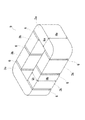
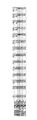
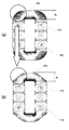
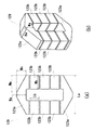
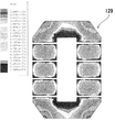
図1は、従来のリアクトル部品のコアを示す斜視図である。図1に示すように、従来のコア9は、例えば、数個の磁性体のブロック3a及び3bと各ブロック間に磁気ギャップとして挿入されるシート材6から形成されている。このコア9の形状は、全体として略リング状になっており、磁性体のブロック3bから成る直線部は2ヶ所あり、各直線部にボビン(図示せず)の巻枠部を介して巻線(図示せず)が巻回され、所定の電気特性が得られる。磁性体のブロック3aは各直線部と結合し、このコア9を略リング状にしている。
FIG. 1 is a perspective view showing a core of a conventional reactor part. As shown in FIG. 1, a
そして、この従来のコア9では、磁路に対し均一なコア断面積を有するコア形状を構成している(例えば、特許文献1参照)。即ち、図1に示すコア9では、磁性体のブロック3aの高さHaと磁性体のブロック3bの高さHbが同一の寸法に形成されると共に磁性体のブロック3aの幅Waと磁性体のブロック3bの幅Wbも同一の寸法に形成されていた
。従って、巻線が巻回される巻回部を構成する磁性体のブロック3bと巻線が巻回されない非巻回部を構成する磁性体のブロック3aが共に磁路と直交する方向の断面積が同じになるようなコア形状を構成していた。
And in this
上述した従来のリアクトル部品では、図1に示したように、磁路に対し均一なコア断面積を有するコア形状を構成していたので、コア9の形状が大きくなり、コストも高くなるという問題があった。コア9の形状が大きければリアクトル全体の小型化・軽量化は困難となり、また、コアは、リアクトルの部品の中でも最も高価な材料であるために、リアクトル全体の低コスト化を困難にしてしまう。
In the conventional reactor parts described above, as shown in FIG. 1, the core shape having a uniform core cross-sectional area with respect to the magnetic path is configured, so that the shape of the
本発明の第1の目的は、リアクトル部品のコア形状を小型化することによりリアクトル全体としての小型化・軽量化・低コスト化も可能とする技術を提供することにある。 A first object of the present invention is to provide a technology that can reduce the size, weight, and cost of the reactor as a whole by reducing the core shape of the reactor component.
また、本発明の第2の目的は、リアクトル部品のコア形状を小型化しながらも高電流領域における直流重畳特性を向上させることができ、且つコア形状の小型化によりリアクトル全体としての小型化・軽量化・低コスト化も可能とする技術を提供することにある。 The second object of the present invention is to improve the DC superposition characteristics in the high current region while reducing the core shape of the reactor component, and to reduce the size and weight of the reactor as a whole by reducing the core shape. It is to provide a technology that can reduce the cost and cost.
リアクトル部品のコアの設計において、従来、同一断面形状で磁路を設計することが一般的に行われていたが、本発明者は、殆ど磁束の通らない部分を削減することにより、高電流領域における直流重畳特性を向上させることができる上にコア形状の小型化を達成可能な最適なコア形状を実現することを見出した。 In designing the core of the reactor component, conventionally, the magnetic path has been generally designed with the same cross-sectional shape, but the present inventor has reduced the high current region by reducing the portion through which the magnetic flux hardly passes. It has been found that an optimum core shape capable of improving the direct current superimposition characteristics and achieving miniaturization of the core shape can be realized.
即ち、上記目的を達成するため、本発明のリアクトル部品は、少なくとも、巻線と磁性体のコアを備え、前記コアは前記巻線が巻回される巻回部と、前記巻線が巻回されない非巻回部とを含み、前記巻回部に前記巻線が巻回されて形成されるリアクトル部品において、前記コアの非巻回部の磁路と直交する方向の断面積を前記巻回部の磁路と直交する方向の断面積に対して小さくしたことを特徴とする。 That is, in order to achieve the above object, the reactor component of the present invention includes at least a winding and a magnetic core, and the core includes a winding portion around which the winding is wound, and the winding is wound. In a reactor part formed by winding the winding around the winding part, a cross-sectional area in a direction orthogonal to the magnetic path of the non-winding part of the core is included in the winding part. The cross-sectional area in the direction orthogonal to the magnetic path of the portion is reduced.
かかる構成により、リアクトル部品のコア形状を小型化することによりリアクトル全体としての小型化・軽量化・低コスト化も可能となる。また、リアクトル部品のコア形状を小型化しながらも高電流領域における直流重畳特性を向上させることができる。 With this configuration, it is possible to reduce the size, weight, and cost of the reactor as a whole by reducing the core shape of the reactor component. In addition, it is possible to improve the DC superimposition characteristics in the high current region while reducing the core shape of the reactor part.
この場合、前記コアの非巻回部の磁路と直交する方向の断面積を前記巻回部の磁路と直交する方向の断面積に対して小さくしたことで、前記非巻回部の方が前記巻回部よりも先に磁気飽和することが考えられ、この結果、高電流領域での直流重畳特性が向上するものと考えられる。 In this case, by reducing the cross-sectional area in the direction orthogonal to the magnetic path of the non-winding portion of the core relative to the cross-sectional area in the direction orthogonal to the magnetic path of the winding portion, Is considered to be magnetically saturated before the winding portion, and as a result, it is considered that the DC superimposition characteristics in a high current region are improved.
また、前記非巻回部の断面積を前記巻回部の断面積の約0.76倍〜約0.67倍にすることが可能である。かかる構成により、リアクトル部品としてのコアひいてはリアクトルの小型化・軽量化・低コスト化が図れる上に、高電流領域において直流重畳特性を向上させることが可能である。 In addition, the cross-sectional area of the non-winding portion can be about 0.76 times to about 0.67 times the cross-sectional area of the winding portion. With this configuration, it is possible to reduce the size, weight, and cost of the core as the reactor component, and thus the reactor, and improve the DC superimposition characteristics in a high current region.
また、本発明は、少なくとも、巻線と磁性体のコアを備え、前記コアは前記巻線が巻回される巻回部と、前記巻線が巻回されない非巻回部とを含み、前記巻回部に前記巻線が巻回されて形成されるリアクトル部品において、前記巻回部は少なくとも2つの矩形平面形状を有する磁性体ブロックが間隔を有して平行に配置され、前記非巻回部は2つの略台形又は略三角形の平面形状を有する磁性体ブロックが前記巻回部を構成する磁性体ブロックをそれぞれの略台形又は略三角形の底部側で挟んで対向して配置されて成り、且つ、前記非巻回部を構成する磁性体ブロックの略台形又は略三角形の頂部における磁路と直交する方向の断面積を前記巻回部を構成する磁性体ブロックの磁路と直交する方向の断面積に対して小さくしたことを特徴とする。かかる構成によれば、前記非巻回部をU字型や矩型の磁性体ブロックにより形成する場合に比べて非巻回部を構成する各磁性体ブロックそのものの体積をより小さくすることができる。従って、リアクトル部品としてのコアひいてはリアクトルの更なる小型化・軽量化・低コスト化を図ることが可能である。 The present invention includes at least a winding and a magnetic core, and the core includes a winding portion around which the winding is wound, and a non-winding portion around which the winding is not wound. In the reactor part formed by winding the winding around the winding part, the winding part includes at least two rectangular flat magnetic body blocks arranged in parallel at intervals, and the non-winding part The part is composed of two substantially trapezoidal or triangular shaped magnetic blocks arranged opposite to each other with the magnetic block constituting the winding part sandwiched between the respective substantially trapezoidal or substantially triangular bottom sides, In addition, the cross-sectional area in the direction perpendicular to the magnetic path at the top of the substantially trapezoidal or substantially triangular shape of the magnetic block constituting the non-winding portion is the direction perpendicular to the magnetic path of the magnetic block constituting the winding portion. Characterized by being smaller than the cross-sectional area . According to this configuration, the volume of each magnetic block itself constituting the non-winding portion can be made smaller than when the non-winding portion is formed of a U-shaped or rectangular magnetic block. . Therefore, it is possible to further reduce the size, weight, and cost of the core as the reactor part and thus the reactor.
尚、前記コアは、磁気ギャップを含む8分割型に構成されていても良い。かかる構成により、前記非巻回部の断面積の削減量に応じた直流重畳特性の向上が顕著になる。 The core may be configured in an eight-divided type including a magnetic gap. With such a configuration, the improvement of the DC superimposition characteristic according to the reduction amount of the cross-sectional area of the non-winding portion becomes remarkable.
また、本発明のリアクトル部品は車載用のリアクトルに用いるのが好適である。車両事故等が生じた場合に回路が故障して車載用のリアクトルに大電流が流れる虞があるため、本発明のリアクトル部品を車載用のリアクトルに用いることで、高電流領域において高いインダクタンス値が得られるため、安全性を向上させることができる。 Moreover, it is suitable to use the reactor component of this invention for the reactor for vehicle mounting. When a vehicle accident or the like occurs, there is a possibility that a circuit breaks down and a large current flows through the in-vehicle reactor. Therefore, by using the reactor component of the present invention in the in-vehicle reactor, a high inductance value is obtained in a high current region. As a result, safety can be improved.
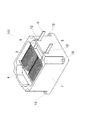
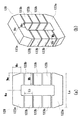
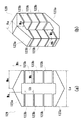
本発明の第1の実施形態に係るリアクトル部品について図面を参照して詳細に説明する。図2は、本実施形態のリアクトル部品を含む一例としてのリアクトルの斜視図である。 A reactor component according to a first embodiment of the present invention will be described in detail with reference to the drawings. FIG. 2 is a perspective view of a reactor as an example including the reactor component of the present embodiment.
図2に示すリアクトル10は、例えば、強制冷却手段を有する機器の電気回路に使用され、巻線2をボビン4に巻回し、ボビン4に後述するコア109(図4参照)を挿入して形成されたリアクトル部品を熱伝導性ケース1に収納した後、充填材8を流し込み固定している。リード部5は巻線2の被覆を剥離し、導体を剥き出しにしており、図示しない圧着端子等を設けて他の電気部品等と接続する。尚、熱伝導性ケース1のリード部用切欠き12は、リード部5と熱伝導性ケース1が干渉しないように形成されており、熱伝導性ケース1は一般的に金属製なので、リード部5を熱伝導性ケース1と絶縁させるため、リード部用切欠き12には絶縁物を挿入している。また、熱伝導性ケース1の4隅にあるリアクトル固定用穴13は、熱伝導性ケース1を例えば、強制冷却された筐体等に固定するためのネジ穴である。
A
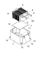
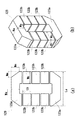
図3は、図2に示したリアクトルの分解斜視図である。図3に示すように、熱伝導性ケース1は熱伝導性ケース底面11と、熱伝導性ケース底面11よりも浅く、段差を有して形成される熱伝導性ケース底面14を含んでいる。図2のリアクトルは熱伝導性ケース底面11に絶縁シート7を敷き、巻線2をボビン4に巻回し、ボビン4にコア109(詳細は図4参照)を挿入して形成されたリアクトル部品を収納している。収納後、熱伝導性ケース底面11は絶縁シート7を介してリアクトル部品の巻線2の図示していない裏面と、熱伝導性ケース底面14はコア109のブロック裏面と、それぞれ接触する。絶縁シート7は、熱伝導性ケース1と巻線2を電気的に絶縁するために、熱伝導性ケース底面11と巻線2間に挿入されている。収納後、充填材8を流し込み、リアクトル部品を熱伝導性ケース1に固定している。
3 is an exploded perspective view of the reactor shown in FIG. As shown in FIG. 3, the thermally
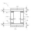
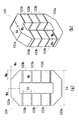
図4は、本実施形態のリアクトル部品のコア109の形状を示す図であり、(a)はその平面図、(b)はその側面図である。図4(a)及び(b)に示すように、本実施形態のリアクトル部品のコア109は、2個の磁性体のブロック103a及び6個の磁性体のブロック103bと各ブロック間に磁気ギャップとして挿入されるシート材106から形成されている。即ち、本実施形態では、コア109は、巻線2(図2及び図3参照)が巻回される巻回部を構成する6個の磁性体のブロック103bと、巻線2が巻回されない非巻回部を構成する2個の磁性体のブロック103aとを含んでおり、巻回部を構成する6個の磁性体のブロック103bに図2及び図3に示したボビン4を介して巻線2が巻回されてリアクトル部品を形成する。図4(a)及び(b)に示すように、このリアクトル部品のコア109の形状は、全体として略リング状になっており、上述した巻回部を構成する6個の磁性体のブロック103bは、それぞれ3個の磁性体のブロック103bから成る2ヶ所の直線部を形成し、各直線部にボビン4の巻枠部を介して巻線2が巻回され、所定の電気特性が得られる。上述した非巻回部を構成する2個の磁性体のブロック103aは、3個の磁性体のブロック103bから成る各直線部とそれぞれ結合し、このコア109を略リング状にしている。尚、シート材106は、磁性体のブロック103b同士の結合部及び磁性体のブロック103aと磁性体のブロック103bとの結合部に磁気ギャップ用に挿入されている。
FIG. 4 is a view showing the shape of the
さて、このリアクトル部品のコア109では、図4(a)及び(b)に示すように、磁性体のブロック103bは均一なコア断面積を有しているが、磁性体のブロック103aは磁性体のブロック103bに対して均一なコア断面積を有していない。即ち、リアクトル部品のコアの設計において、図1に示した従来のリアクトル部品のコア9では、同一断面形状で磁路を設計していたが、本実施形態のリアクトル部品のコア109では、各磁性体のブロック103aにおける殆ど磁束の通らない部分を削減するようにし、コア109の非巻回部を構成する2個の磁性体のブロック103aにおける磁路と直交する方向の断面積を巻回部を構成する各個の磁性体のブロック103bの磁路と直交する方向の断面積に対して小さくした。
In the
ここで、本実施形態におけるコア109を形成する各磁性体のブロックの寸法を述べる。各磁性体のブロック103bは、図4(a)に示すコア(ブロック)幅Wbが27.0mm、ブロック長さLbが16.5mmに形成した。一方、磁性体のブロック103aは、図4(a)に示すブロック長さLaは72.0mm、コア(ブロック)幅W1aを20.5mm〜18.0mmの範囲内に形成した。また、磁性体のブロック103aの高さHaと磁性体のブロック103bの高さHbは、図4(b)に示すように、共に27.5mmであり、同一の寸法に形成されている。従って、巻線が巻回される巻回部を構成する磁性体のブロック103bの磁路と直交する方向の断面積Wb*Hbは742.5mm2であるのに対し、巻線が巻回されない非巻回部を構成する磁性体のブロック103aの断面積W1a*Haは563.75mm2〜495.0mmである。従って、非巻回部を構成する磁性体のブロック103aの磁路と直交する方向の断面積W1a*Haは、巻回部を構成する磁性体のブロック103bの磁路と直交する方向の断面積Wb*Hbの約76%〜約67%(約0.76倍〜約0.67倍)に留まっている。換言すれば、非巻回部を構成する磁性体のブロック103aの断面積W1a*Haを巻回部を構成する磁性体のブロック103bの断面積Wb*Hbよりも約24%〜約33%小さくしている。尚、図4(a)及び(b)に示すように、磁性体のブロック103aは、その両角部を除いて主要部分が略この断面積W1a*Haにて形成されているので、断面積W1a*Haを小さくすれば磁性体のブロック103aの体積が大幅に削減される。従って、2個の磁性体のブロック103aの体積がそれぞれ削減されることにより、コア109全体の小型化・低コスト化が達成される。
Here, the dimensions of the blocks of the magnetic bodies forming the core 109 in this embodiment will be described. Each
尚、図4(a)及び(b)に一点鎖線で示しているのは、磁性体のブロック103aのコア(ブロック)幅WCaを、磁性体のブロック103bのコア(ブロック)幅Wbと同一の27.0mmとした場合、即ち、非巻回部を構成する磁性体のブロック103aの断面積WCa*Haを巻回部を構成する磁性体のブロック103bの断面積Wb*Hbに対して小さくしない場合のコア形状である。また、図4(a)及び(b)に点線で示しているのは、磁性体のブロック103aのコア(ブロック)幅W2aを更に小さくする、後述する本発明の第2の実施形態におけるコア形状である。
In FIGS. 4A and 4B, the one-dot chain line indicates that the core (block) width WCa of the
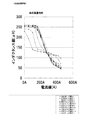
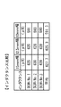
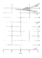
図5は、上述したように、磁性体のブロック103aのコア(ブロック)幅W1aを20.5mm〜18.0mmの範囲内で変えてコア109を含むリアクトル部品を形成し、そのリアクトル部品を含んだリアクトルについて、それぞれ各電流値(A)に対するインダクタンス値(μH)を測定し、表にまとめたものである。尚、比較例として、磁性体のブロック103aのコア(ブロック)幅WCaを、従来例と同様に、磁性体のブロック103bのコア(ブロック)幅Wbと同じ27.0mmとした場合について測定した同様の値を示す。また、図6は、これらの関係をグラフに示したものである。
5, as described above, the core (block) width W1a of the
図5及び図6においては、図4に示した磁性体のブロック103aのコア(ブロック)幅W1aを、20.5mm(実施例1)、20.0mm(実施例2)、19.5mm(実施例3)、19.0mm(実施例4)、18.5mm(実施例5)、18.0mm(実施例6)というように、20.5mmから18.0mmまでの範囲内で0.5mm単位で変えたコア109を用いたリアクトル部品を含むリアクトルについて、それぞれ電流値が0(A)から450(A)まで14段階の電流値に対して各インダクタンス値(μH)が示されている。
5 and 6, the core (block) width W1a of the
特に、図6のグラフから明瞭なように、実施例1から実施例6までの全てのコア(ブロック)幅のケースで、0(A)から160(A)までの範囲の電流値に対して各インダクタンス値(μH)は、比較例のケースと略同様の値である250(μH)前後の値を示している。従って、本実施形態のようにコア(ブロック)幅W1aを20.5mm〜18.0mmの範囲内で削減するのであれば、かかる50(A)から160(A)までの比較的低電流の領域において、全く削減しない場合[コア(ブロック)幅WCaが27.0mmの場合]と同様に高いインダクタンス値が得られる。これにより、本実施形態のようにコア(ブロック)幅W1aを20.5mm〜18.0mmの範囲内で削減するのであれば、全く削減しない場合と同様に0(A)から160(A)までの比較的低電流の領域においてリアクトルとしての機能を十分に果たせることを確認できた。 In particular, as is clear from the graph of FIG. 6, in the case of all the core (block) widths from the first embodiment to the sixth embodiment, for current values in the range from 0 (A) to 160 (A). Each inductance value (μH) is a value around 250 (μH) which is substantially the same value as the case of the comparative example. Therefore, if the core (block) width W1a is reduced within the range of 20.5 mm to 18.0 mm as in the present embodiment, the relatively low current region from 50 (A) to 160 (A). , A high inductance value can be obtained in the same manner as in the case where the core (block) width WCa is 27.0 mm. Thus, if the core (block) width W1a is reduced within the range of 20.5 mm to 18.0 mm as in the present embodiment, from 0 (A) to 160 (A) as in the case of no reduction at all. It was confirmed that the reactor can function sufficiently in the relatively low current region.
ところで、図6のグラフから明瞭なように、実施例1から実施例6までの全てのコア(ブロック)幅のケースで、300(A)以上[300(A)から450(A)まで]の比較的高電流の領域において、各インダクタンス値(μH)は、比較例のケースと同等又はそれ以上の高い値を示している。従って、本実施形態のようにコア(ブロック)幅W1aを20.5mm〜18.0mmの範囲内で削減するのであれば、かかる300(A)以上の比較的高電流の領域において、全く削減しない場合[コア(ブロック)幅WCaが27.0mmの場合]以上の高いインダクタンス値が得られる。これにより、本実施形態のようにコア(ブロック)幅W1aを20.5mm〜18.0mmの範囲内で削減するのであれば、全く削減しない場合に比べ、300(A)以上の比較的高電流領域において直流重畳特性が著しく改善されることを確認できた。即ち、300(A)以上の比較的高電流が流れる場合でも、全く削減しない場合よりも更にリアクトルとしての安全性が高まることを確認できた。従って、本実施形態のようにコア(ブロック)幅W1aをコア(ブロック)幅Wbの約0.76倍〜約0.67倍の範囲内にすることにより、上述したようにリアクトルの小型化・低コスト化が図れる上に300(A)以上の比較的高電流領域において直流重畳特性を向上させることが可能である。尚、この場合、コア109の非巻回部を構成する磁性体のブロック103aの磁路と直交する方向の断面積W1a*Haを巻回部を構成する磁性体のブロック103bの磁路と直交する方向の断面積Wb*Hbに対して小さくすることで、非巻回部の方が巻回部よりも先に磁気飽和することが考えられ、この結果、高電流領域での直流重畳特性が向上するものと考えられる。
By the way, as is clear from the graph of FIG. 6, in the case of all the core (block) widths from the first embodiment to the sixth embodiment, 300 (A) or more [from 300 (A) to 450 (A)]. In a relatively high current region, each inductance value (μH) is equal to or higher than the case of the comparative example. Therefore, if the core (block) width W1a is reduced within the range of 20.5 mm to 18.0 mm as in the present embodiment, it is not reduced at all in such a relatively high current region of 300 (A) or more. In the case [when the core (block) width WCa is 27.0 mm], a higher inductance value is obtained. Accordingly, if the core (block) width W1a is reduced within the range of 20.5 mm to 18.0 mm as in the present embodiment, a relatively high current of 300 (A) or more is obtained as compared with a case where the core (block) width W1a is not reduced at all. It was confirmed that the DC superposition characteristics were remarkably improved in the region. That is, it was confirmed that even when a relatively high current of 300 (A) or more flows, the safety as a reactor is further improved as compared with the case where no reduction is made. Therefore, by reducing the core (block) width W1a within the range of about 0.76 times to about 0.67 times the core (block) width Wb as in the present embodiment, the reactor can be downsized as described above. In addition to cost reduction, it is possible to improve DC superposition characteristics in a relatively high current region of 300 (A) or more. In this case, the cross-sectional area W1a * Ha in the direction perpendicular to the magnetic path of the
例えば、本実施形態のようなリアクトルを車載用(ハイブリッド車に流れるモータ電流の制御等の用途)に用いる場合、上述した0(A)から160(A)までの比較的低電流の領域が通常の使用領域となることが多い。また、車両事故等が生じた場合に回路が故障して車載用のリアクトルにも瞬間的に大電流が流れる虞があるため、安全性の観点から300(A)以上の比較的高電流の領域において高いインダクタンス値が得られることは大変望ましい。従って、本実施形態のようにコア(ブロック)幅W1aを20.5mm〜18.0mmの範囲内で削減することにより、かかる車載用のリアクトルに最適なリアクトル部品としてのコアを提供することができる。 For example, when the reactor as in the present embodiment is used for in-vehicle use (for controlling the motor current flowing in the hybrid vehicle, etc.), the above-described region of relatively low current from 0 (A) to 160 (A) is usually used. Often used as a usage area. In addition, in the event of a vehicle accident or the like, a circuit breaks down and there is a possibility that a large current may flow instantaneously through the in-vehicle reactor. Therefore, from the viewpoint of safety, a relatively high current region of 300 (A) or more It is highly desirable to obtain a high inductance value at Therefore, by reducing the core (block) width W1a within the range of 20.5 mm to 18.0 mm as in the present embodiment, it is possible to provide a core as a reactor component that is optimal for such a vehicle-mounted reactor. .
次に、本発明の第2の実施形態に係るリアクトル部品について説明する。本実施形態のリアクトル部品及び該リアクトル部品を含むリアクトルの基本的構成は、図2乃至図4に示した第1の実施形態のものと同様である。従って、この第2の実施形態においても、コア109は第1の実施形態と同様に全体として8分割に構成されている。一方、この第2の実施形態では、上述したコア109の非巻回部の磁路と直交する方向の断面積を巻回部の磁路と直交する方向の断面積に対して小さくするための削減量を第1の実施形態よりも更に多くしたことを特徴としている。即ち、本実施形態においては、磁性体のブロック103aの図4(a)に示したコア(ブロック)幅W2aを15.0mm〜5.0mmの範囲内に形成した。
Next, a reactor part according to a second embodiment of the present invention will be described. The basic structure of the reactor component of this embodiment and the reactor containing this reactor component is the same as that of the 1st Embodiment shown in FIG. 2 thru | or FIG. Accordingly, also in the second embodiment, the
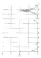
図7は、上述したように、磁性体のブロック103aのコア(ブロック)幅W2aを15.0mm〜5.0mmの範囲内で変えてコア109を含むリアクトル部品を形成し、そのリアクトル部品を含むリアクトルについて、それぞれ各電流値(A)に対するインダクタンス値(μH)を測定し、上述した第1の実施形態における実施例1〜実施例6に追加する実施例7、実施例8及び実施例9として表にまとめたものである。また、第1の実施形態において測定した磁性体のブロック103aのコア(ブロック)幅WCaを27.0mmとした比較例の値も同様に示す。図8は、これらの関係をグラフに示したものである。
In FIG. 7, as described above, the core (block) width W2a of the
図7及び図8においては、図4に示した磁性体のブロック103aのコア(ブロック)幅W2aを、15.0mm(実施例7)、10.0mm(実施例8)、5.0mm(実施例9)というように、15.0mmから5.0mmの範囲内で5mm単位で変えたコア109を用いたリアクトル部品を含むリアクトルについて、それぞれ電流値が0(A)から450(A)まで14段階の電流値に対して各インダクタンス値(μH)が示されている。
7 and 8, the core (block) width W2a of the
特に、図7の表から明瞭なように、本実施形態における実施例9のコア(ブロック)幅のケースで、非駆動時である0(A)は除いて駆動時である50(A)からすぐにインダクタンス値(μH)が低下する。また、実施例8のコア(ブロック)幅のケースで、130(A)からインダクタンス値(μH)がかなり低下する。更に、実施例7のコア(ブロック)幅のケースで、200(A)からインダクタンス値(μH)がかなり低下する。一方、図8のグラフから明瞭なように、本実施形態における実施例7、実施例8及び実施例9の全てのコア(ブロック)幅のケースで、300(A)以上[300(A)から450(A)まで]の比較的高電流の領域において、各インダクタンス値(μH)は、比較例のケースよりも大幅に高い値を示している。従って、本実施形態のようにコア(ブロック)幅W2aを15.0mm〜5.0mmの範囲内で削減するのであれば、かかる300(A)以上の比較的高電流の領域において、全く削減しない場合[コア(ブロック)幅WCaが27.0mmの場合]よりも大幅に高いインダクタンス値が得られる。これにより、本実施形態のようにコア(ブロック)幅W2aを15.0mm〜5.0mmの範囲内で削減するのであれば、全く削減しない場合に比べ、300(A)以上の比較的高電流領域において直流重畳特性が改善されることを確認できた。即ち、300(A)以上の比較的高電流が流れる場合でも、全く削減しない場合よりも更にリアクトルとしての安全性が高まることを確認できた。従って、本実施形態のようにコア(ブロック)幅W2aをコア(ブロック)幅Wbの約0.76倍〜約0.67倍の範囲内にすることにより、上述したようにリアクトルの小型化・低コスト化が図れる上に300(A)以上の比較的高電流領域において直流重畳特性を改善することが可能である。尚、この場合も、コア109の非巻回部を構成する磁性体のブロック103aの磁路と直交する方向の断面積W2a*Haを巻回部を構成する磁性体のブロック103bの磁路と直交する方向の断面積Wb*Hbに対して更に小さくすることで、非巻回部の方が巻回部よりも更に先に磁気飽和することが考えられ、この結果、高電流領域での直流重畳特性が改善されるものと考えられる。
In particular, as is clear from the table of FIG. 7, in the case of the core (block) width of Example 9 in this embodiment, from 0 (A) when not driven to 50 (A) when driven. The inductance value (μH) immediately decreases. Further, in the case of the core (block) width of the eighth embodiment, the inductance value (μH) is considerably reduced from 130 (A). Further, in the case of the core (block) width of the seventh embodiment, the inductance value (μH) is considerably reduced from 200 (A). On the other hand, as is clear from the graph of FIG. 8, in the case of all the core (block) widths of Example 7, Example 8, and Example 9 in this embodiment, 300 (A) or more [from 300 (A) In the region of relatively high current [up to 450 (A)], each inductance value (μH) shows a value significantly higher than that of the comparative example. Therefore, if the core (block) width W2a is reduced within the range of 15.0 mm to 5.0 mm as in the present embodiment, it is not reduced at all in such a relatively high current region of 300 (A) or more. An inductance value significantly higher than that in the case [when the core (block) width WCa is 27.0 mm] is obtained. Accordingly, if the core (block) width W2a is reduced within the range of 15.0 mm to 5.0 mm as in the present embodiment, a relatively high current of 300 (A) or more is obtained as compared with the case where the core (block) width W2a is not reduced at all. It was confirmed that the DC superposition characteristics were improved in the region. That is, it was confirmed that even when a relatively high current of 300 (A) or more flows, the safety as a reactor is further improved as compared with the case where no reduction is made. Therefore, by reducing the core (block) width W2a within the range of about 0.76 times to about 0.67 times the core (block) width Wb as in this embodiment, the reactor can be reduced in size as described above. In addition to cost reduction, it is possible to improve DC superposition characteristics in a relatively high current region of 300 (A) or more. In this case as well, the cross-sectional area W2a * Ha in the direction orthogonal to the magnetic path of the
尚、実施例7のコア(ブロック)幅のケースで、0(A)から130(A)までの比較的低電流領域では、240(μH)以上の値を示している。従って、実施例7のようにコア(ブロック)幅W2aを15.0mmまで削減するのであれば、かかる0(A)から130(A)までの比較的低電流の領域において、全く削減しない場合[コア(ブロック)幅WCaが27.0mmの場合]や第1の実施形態のように20.5mm〜18.0mmの範囲内で削減する場合と同様に高いインダクタンス値が得られる。従って、実施例7のようにコア(ブロック)幅W2aを15.0mmまで削減するのであれば、0(A)から130(A)までの比較的低電流の領域においてリアクトルとしての機能を十分に果たせることを確認できた。 In the case of the core (block) width of the seventh embodiment, a value of 240 (μH) or more is shown in a relatively low current region from 0 (A) to 130 (A). Therefore, if the core (block) width W2a is reduced to 15.0 mm as in the seventh embodiment, it is not reduced at all in the relatively low current region from 0 (A) to 130 (A) [ When the core (block) width WCa is 27.0 mm] or in the case of reduction within the range of 20.5 mm to 18.0 mm as in the first embodiment, a high inductance value is obtained. Therefore, if the core (block) width W2a is reduced to 15.0 mm as in the seventh embodiment, the function as a reactor is sufficiently obtained in a relatively low current region from 0 (A) to 130 (A). I was able to confirm that I could do it.
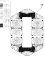
続いて、本発明の第3の実施形態に係るリアクトル部品について説明する。本実施形態のリアクトル部品及び該リアクトル部品を含むリアクトルの基本的構成を図9及び図10に示す。図9は、本実施形態のリアクトル部品のコア119の形状を示す平面図であり、図10は、そのコア119を含むリアクトルを示す図である。図9に示すように、この第3の実施形態においては、上述した第1及び第2の実施形態と異なり、コア119は全体として4分割に構成されている。本実施形態のリアクトル部品のコア119は、2個の磁性体のブロック113a及び2個の磁性体のブロック113bと各ブロック間に磁気ギャップとして挿入されるシート材116から形成されている。即ち、本実施形態では、コア119は、図10に示す巻線112が巻回される巻回部を構成する2個の磁性体のブロック113bと、巻線112が巻回されない非巻回部を構成する2個の磁性体のブロック113aとを含んでおり、巻回部を構成する2個の磁性体のブロック113bに図示しないボビンを介して巻線112が巻回されてリアクトル部品を形成し、所定の電気特性が得られる。尚、シート材116は、磁性体のブロック113aと磁性体のブロック113bとの結合部に磁気ギャップ用に挿入されている。
Subsequently, a reactor part according to a third embodiment of the present invention will be described. 9 and 10 show a basic configuration of the reactor component of the present embodiment and the reactor including the reactor component. FIG. 9 is a plan view showing the shape of the
さて、このリアクトル部品のコア119では、図9に示すように、磁性体のブロック113bは均一なコア断面積を有しているが、磁性体のブロック113aは磁性体のブロック113bに対して均一なコア断面積を有していない。即ち、従来のかかるコアでは、同一断面形状で磁路を設計していたが、本実施形態のリアクトル部品のコア119では、各磁性体のブロック113aにおける殆ど磁束の通らない部分を削減するようにし、コア119の非巻回部を構成する2個の磁性体のブロック113aにおける磁路と直交する方向の断面積を巻回部を構成する2個の磁性体のブロック113bの磁路と直交する方向の断面積に対して小さくした。
In the
ここで、本実施形態においては、磁性体のブロック113bのコア(ブロック)幅W3bが15.0mmであるのに対し、磁性体のブロック113aのコア(ブロック)幅W3aを同様の15.0mmから12.5mmと10.0mmに削減して形成した。尚、図9には示さないが、磁性体のブロック113aの高さH3aと磁性体のブロック113bの高さH3bは同一寸法である。従って、巻線が巻回される巻回部を構成する磁性体のブロック113bの磁路と直交する方向の断面積W3b*H3bに対し、巻線が巻回されない非巻回部を構成する磁性体のブロック113aの断面積W3a*H3aは、それぞれ約0.83倍、約0.67倍に留まっている。換言すれば、非巻回部を構成する磁性体のブロック113aの断面積W3a*H3aを巻回部を構成する磁性体のブロック113bの断面積W3b*H3bよりも、それぞれ約17%、約33%削減している。尚、磁性体のブロック113aは、その長さ方向に亘ってこの断面積W3a*H3aにて形成されているので、断面積W3a*H3aを削減すれば磁性体のブロック113aの体積が削減される。従って、2個の磁性体のブロック113aの体積がそれぞれ削減されることにより、コア119全体の小型化・低コスト化が達成される。
Here, in the present embodiment, the core (block) width W3b of the
尚、図9に破線で示しているのは、磁性体のブロック113aのコア(ブロック)幅W3Caを、磁性体のブロック113bのコア(ブロック)幅W3bと同一の15.0mmとした場合、即ち、非巻回部を構成する磁性体のブロック113aの断面積W3Ca*H3aを巻回部を構成する磁性体のブロック113bの断面積W3b*H3bに対して小さくしない場合のコア形状である。
In FIG. 9, the broken line indicates that the core (block) width W3Ca of the
図11は、上述したように、磁性体のブロック113aのコア(ブロック)幅W3aを12.5mm(実施例10)、10.0mm(実施例11)と変えてコア119を含むリアクトル部品を形成し、そのリアクトル部品を、図10に示したように用いたリアクトルに関し、No.1、No.2及びNo.3の3個の試料を製作し、それぞれ電流値(20A)に対するインダクタンス値(μH)を測定し、表にまとめたものである。尚、比較例として、磁性体のブロック113aのコア(ブロック)幅W3Caを従来例と同様に15.0mmとした場合について測定した同様の値を示す。
In FIG. 11, as described above, the core (block) width W3a of the
図11においては、図9に示した磁性体のブロック113aのコア(ブロック)幅W3aを、12.5mm(実施例10)、10.0mm(実施例11)としたコア119を用いたリアクトル110について、No.1、No.2及びNo.3の3個の試料について、それぞれ10KHz、1V、DC20(A)の測定条件で各インダクタンス値(μH)を測定した。図11から明瞭なように、磁性体のブロック113aのコア(ブロック)幅W3aを12.5mmとした実施例10においては、No.1、No.2及びNo.3の全ての試料において、各インダクタンス値(μH)は、比較例のケースと略同様の値を示している[3個の試料平均でインダクタンス値(μH)は0.4%低下した]。従って、本実施形態のようにコア(ブロック)幅W3aを12.5mmまで削減するのであれば、かかる条件下において、全く削減しない場合[コア(ブロック)幅W3Caが15.0mmの場合]と同様のインダクタンス値が得られる。これにより、本実施形態のようにコア(ブロック)幅W3aを12.5mmまで削減するのであれば、全く削減しない場合と同様に図10に示したリアクトルとしての機能を十分に果たせることを確認できた。
In FIG. 11, a reactor 110 using a
図12は、図11の場合と同様に、磁性体のブロック113aのコア(ブロック)幅Waを12.5mm(実施例10)、10.0mm(実施例11)と変えてコア119を含むリアクトル部品を形成し、そのリアクトル部品を、図10に示したように用いたリアクトルを駆動した場合に、図10に示す(1)コイル間、(2)コイル表面、(3)リアクトル上面、(4)周囲温度の4点に関し、それぞれの温度上昇の度合いを比較して表にまとめたものである。尚、比較例として、磁性体のブロック113aのコア(ブロック)幅W3Caを従来例と同様に15.0mmとした場合について測定した同様の値を示す。
12, similarly to the case of FIG. 11, the core (block) width Wa of the
図12においては、図9に示した磁性体のブロック113aのコア(ブロック)幅W3aを、12.5mm(実施例10)、10.0mm(実施例11)としたコア119を用いたリアクトル110について、図11の測定条件で駆動した場合の(1)コイル間、(2)コイル表面、(3)リアクトル上面、(4)周囲温度の4点に関し、それぞれの温度(℃)と、非駆動時からの温度上昇分Δt(℃)を測定した。図12から明瞭なように、磁性体のブロック113aのコア(ブロック)幅W3aを12.5mmとした実施例10においては、温度上昇値は比較例のケースと略同様の値を示している[平均で比較例よりも1.4%程度大きく上昇した]。従って、本実施形態のようにコア(ブロック)幅W3aを12.5mmまで削減するのであれば、かかる条件下において、全く削減しない場合[コア(ブロック)幅W3Caが15.0mmの場合]と同様の温度特性が得られる。
In FIG. 12, the reactor 110 using the
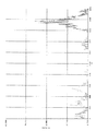
更に、以上と同様に、磁性体のブロック113aのコア(ブロック)幅W3aを12.5mm(実施例10)、10.0mm(実施例11)と変えてコア119を含むリアクトル部品を形成し、そのリアクトル部品を、図10に示したように用いたリアクトルを駆動した場合に生じる騒音をそれぞれ測定した。比較例として、磁性体のブロック113aのコア(ブロック)幅W3Caを従来例と同様に15.0mmとした場合についても、同様の騒音を測定した。図13は、15.0mmとした比較例の騒音データの測定結果、図14は、12.5mmとした実施例10の騒音データの測定結果、図15は、10.0mmとした実施例11の騒音データの測定結果をそれぞれ示す。
Further, similarly to the above, the core (block) width W3a of the
図13及び図14から分かるように、12.5mmとした実施例10では、15.0mmとした場合と比較して騒音の差は殆ど無い。これに対して、図13及び図15から分かるように、10.0mmとした実施例11では、15.0mmとした場合と比較して、2KHz〜6KHzの周波数領域でのノイズが増加する等、騒音がやや悪化している。これは、10.0mmとした実施例11では、断面積が小さくなった分、磁束が集中し、電磁吸引力によるコアの振動による騒音が増加したものと考えられる。 As can be seen from FIGS. 13 and 14, in Example 10 in which 12.5 mm is set, there is almost no difference in noise compared to the case in which 15.0 mm is set. On the other hand, as can be seen from FIGS. 13 and 15, in Example 11 with 10.0 mm, noise in the frequency region of 2 KHz to 6 KHz increases compared to the case with 15.0 mm. The noise is getting worse. In Example 11 with 10.0 mm, it is considered that the magnetic flux was concentrated as much as the cross-sectional area was reduced, and the noise due to the vibration of the core due to the electromagnetic attractive force increased.
次に、本発明の第4の実施形態に係るリアクトル部品について説明する。本実施形態のリアクトル部品のコアの構成を図16乃至図22に示し、更に、対応するコアの磁束分布状態を図23乃至図28に示す。 Next, a reactor part according to a fourth embodiment of the present invention will be described. The structure of the core of the reactor component of this embodiment is shown in FIGS. 16 to 22, and the magnetic flux distribution state of the corresponding core is shown in FIGS.
本実施形態の特徴は、上述した第1乃至第3の実施形態と同様に、巻回部は少なくとも2つの矩形平面形状を有する磁性体ブロックが間隔を有して平行に配置されて成るが、非巻回部は2つの略台形又は略三角形の平面形状を有する磁性体ブロックが巻回部を構成する磁性体ブロックをそれぞれの略台形又は略三角形の底部側で挟んで対向して配置されて成り、且つ、非巻回部を構成する磁性体ブロックの略台形又は略三角形の頂部における磁路と直交する方向の断面積を巻回部を構成する磁性体ブロックの磁路と直交する方向の断面積に対して小さくしたことを特徴とする。かかる構成によれば、非巻回部をU字型の磁性体ブロックや矩形の磁性体ブロックにより形成する場合に比べて、非巻回部を構成する各磁性体ブロックそのものの体積をより小さくすることができる。従って、リアクトル部品としてのコアひいてはリアクトルの更なる小型化・軽量化・低コスト化を図ることが可能である。 The feature of this embodiment is that, as in the first to third embodiments described above, the winding portion is formed by arranging magnetic blocks having at least two rectangular planar shapes in parallel with a gap therebetween. The non-winding portion is arranged so that two magnetic blocks having a substantially trapezoidal or substantially triangular planar shape sandwich the magnetic blocks constituting the winding portion at the bottom side of each substantially trapezoidal or substantially triangular shape. And the cross-sectional area in the direction perpendicular to the magnetic path at the top of the substantially trapezoidal or substantially triangular shape of the magnetic block constituting the non-winding portion is the direction perpendicular to the magnetic path of the magnetic block constituting the winding portion. It is characterized by having a smaller cross-sectional area. According to such a configuration, the volume of each magnetic body block itself constituting the non-winding portion is made smaller than when the non-winding portion is formed of a U-shaped magnetic body block or a rectangular magnetic body block. be able to. Therefore, it is possible to further reduce the size, weight, and cost of the core as the reactor part and thus the reactor.
この第4の実施形態においても、従来、同一断面形状で磁路を設計することが一般的に行われていたのに対し、殆ど磁束の通らない部分を削減することにより、高電流領域における直流重畳特性を確保しつつ、小型化を達成可能なコア形状の最適化を図るということが発明の本質となっており、第1乃至第3の実施形態と同様の技術思想に基づいている。 In the fourth embodiment as well, conventionally, the magnetic path is generally designed with the same cross-sectional shape, but the direct current in the high current region is reduced by reducing the portion through which the magnetic flux hardly passes. The essence of the invention is to optimize the core shape that can achieve miniaturization while ensuring the superimposition characteristics, and is based on the same technical idea as the first to third embodiments.
即ち、この第4の実施形態の実施例1及び変形例1乃至5においても、上述した第1乃至第3の実施形態と同様に、巻線2(図2及び図3参照)や112(図10参照)が巻回されない非巻回部を構成する2個の磁性体のブロック123aそれぞれの幅Waを巻回部を構成する各個の磁性体のブロック123bの幅Wbよりも狭くなるように削減することで、コア129の非巻回部を構成する2個の磁性体のブロック123aにおける磁路と直交する方向の断面積を巻回部を構成する2個の磁性体のブロック123bの磁路と直交する方向の断面積に対して小さくしている。しかしながら、この第4の実施形態の実施例1及び変形例1乃至5においては、第1乃至第3の実施形態と異なり、非巻回部を構成する2個の磁性体のブロック123aそれぞれを第1及び第2の実施形態のようなU字型の磁性体ブロックや第3の実施形態のような矩形の磁性体ブロックではなく、略台形又は略三角形の平面形状を有する磁性体ブロックにより形成し、それぞれの略台形又は略三角形の底部側で巻回部を構成する2個の磁性体のブロック123bを挟んで対向して配置されて成ることにより、非巻回部を構成する磁性体ブロック123aの略台形又は略三角形の頂部における磁路と直交する方向の断面積を巻回部を構成する磁性体ブロック123bの磁路と直交する方向の断面積に対して小さくしている。
That is, also in Example 1 and
かかる構成により、非巻回部をU字型の磁性体ブロックや矩形の磁性体ブロックにより形成する場合に比べて、コア129全体の長さは同じだとしても、非巻回部を構成する各磁性体ブロック123aそのものの体積をより小さくすることができる。従って、リアクトル部品としてのコアひいてはリアクトルの更なる小型化・軽量化・低コスト化を図ることが可能である。
With this configuration, even if the entire length of the
尚、本実施形態は、上述した第1及び第2の実施形態と比較した場合、上述した第1及び第2の実施形態における2個のU字型の磁性体ブロック103aそれぞれの両角部(ラウンド状の両角部)が平面状になるようにカットしたのと同様の関係にあることから、上述した第1及び第2の実施形態における非巻回部のコア幅等の最適値等をそのまま使用する(換言すれば、略台形又は略三角形の高さ[略台形又は略三角形の頂部におけるコア幅]をこの最適値に設計する)ことにより実現することができる。
In this embodiment, when compared with the first and second embodiments described above, both corners (round) of each of the two U-shaped
本発明者は、上述したように殆ど磁束の通らない部分を削減することにより小型化を達成可能なコア形状の最適化を図るという観点から、本実施形態において、図16に示す実施例1の他に同図(a)に示す寸法Wmを変化させた変形例1乃至5に係るリアクトル部品のコアを設計し、それぞれの磁束分布状態をシュミレーションにより観測し、非巻回部を構成する各磁性体のブロック123aの略台形又は略三角形における最適な形状を求めるようにした。
From the viewpoint of optimizing the core shape that can achieve miniaturization by reducing the portion through which the magnetic flux hardly passes as described above, the inventor of the first embodiment shown in FIG. In addition, the cores of the reactor parts according to the modified examples 1 to 5 in which the dimension Wm shown in FIG. 5A is changed are designed, the respective magnetic flux distribution states are observed by simulation, and the respective magnets constituting the non-winding portion are designed. The optimum shape of the trapezoid or triangle of the
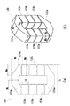
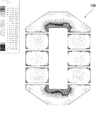
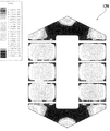
まず、本実施形態の実施例1のリアクトル部品のコアの構成を詳細に説明する。図16は、本発明の第4の実施形態の実施例1に係るリアクトル部品のコアの形状を示す図であり、(a)はその平面図、(b)はその斜視図である。本実施形態の実施例1のリアクトル部品のコアは、図16(a)及び(b)に示すように、コア129は全体として8分割に構成されている。本実施形態のリアクトル部品のコア129は、2個の磁性体のブロック123a及び6個の磁性体のブロック123bと各ブロック間に磁気ギャップとして挿入されるシート材(図示せず)から形成されている。そして、巻線2が巻回されない非巻回部を2つの略台形の平面形状を有する磁性体ブロック123aから構成し、その略台形の底部側で巻回部を構成する各3個の磁性体ブロック123bを挟んで対向して配置することにより、非巻回部を構成する磁性体ブロック123aの略台形の頂部における磁路と直交する方向の断面積を巻回部を構成する各個の磁性体ブロック123bの磁路と直交する方向の断面積に対して小さくなるようにしている。
First, the structure of the core of the reactor part of Example 1 of this embodiment will be described in detail. FIG. 16: is a figure which shows the shape of the core of the reactor component which concerns on Example 1 of the 4th Embodiment of this invention, (a) is the top view, (b) is the perspective view. As shown in FIGS. 16 (a) and 16 (b), the core of the reactor part of Example 1 of the present embodiment is configured by dividing the
尚、このリアクトル部品のコア129の形状は、全体として略リング状であるがリングの4つのラウンド部が平面状にカットされたような形状になっており、上述した巻回部を構成する6個の磁性体のブロック123bは、それぞれ3個の磁性体のブロック123bから成る2ヶ所の直線部を形成し、各直線部に図3に示したようなボビン4の巻枠部を介して巻線2が巻回され、所定の電気特性が得られる。
The
ここで、本実施形態の実施例1におけるコア129を形成する各磁性体のブロックの寸法を述べる。各磁性体のブロック123bは、図16(a)に示すコア(ブロック)幅Wbが27.0mm、ブロック長さLbが16.5mmに形成した。一方、磁性体のブロック123aは、図16(a)に示すブロック長さLaは72.0mm、略台形状の頂部(頂辺)におけるコア(ブロック)幅Waを18.0mmに形成した。また、図16(b)に示す磁性体のブロック123aの高さHaと磁性体のブロック123bの高さHbは、共に27.5mmであり、同一の寸法に形成されている。
Here, the dimension of each magnetic body block forming the core 129 in Example 1 of the present embodiment will be described. Each
以上により、この第4の実施形態の実施例1においては、巻線が巻回される巻回部を構成する磁性体のブロック123bの磁路と直交する方向の断面積Wb*Hbは742.5mm2であるのに対し、巻線が巻回されない非巻回部を構成する磁性体のブロック123aの略台形状の頂部(頂辺)における断面積Wa*Haは495.0mm2である。このように、本実施例1においても、上述した第1乃至第3の実施形態と同様に、コアの非巻回部の磁路と直交する方向の断面積を巻回部の磁路と直交する方向の断面積に対して小さくしている。具体的には、第1の実施形態の実施例6と同様に、非巻回部を構成する磁性体のブロック123aの磁路と直交する方向の断面積Wa*Haは、巻回部を構成する磁性体のブロック123bの磁路と直交する方向の断面積Wb*Hbの約67%(約0.67倍)に留まっている。換言すれば、非巻回部を構成する磁性体のブロック123aの断面積Wa*Haを巻回部を構成する磁性体のブロック123bの断面積Wb*Hbよりも約33%小さくしている。
As described above, in Example 1 of the fourth embodiment, the cross-sectional area Wb * Hb in the direction perpendicular to the magnetic path of the
更に、この第4の実施形態の実施例1においては、図16(a)及び(b)に示すように、非巻回部を構成する各磁性体ブロック123aが略台形に形成されているので、上記の断面積Wa*Ha(495.0mm2)は略台形状の頂部(頂辺)における断面積であり、この頂部(頂辺)における断面積が巻回部を構成する磁性体のブロック123bの磁路と直交する方向の断面積Wb*Hb(742.5mm2)に対して小さくなっている。このように、非巻回部を構成する各磁性体ブロック123aが略台形に形成されていることから、各磁性体ブロック123aの体積は、U字型の磁性体ブロックを用いた第1の実施形態の実施例6に比べて、更に約30%削減されている。従って、各磁性体のブロック123aの体積が大幅に削減される結果、コア129全体の更なる小型化・低コスト化が達成される。尚、図16(a)において、Wa、Wb、Wn、Wmの寸法比は、Wa=Wb×2/3(約0.67)、Wn=Wa(一定)、Wm=Wbとなるように形成されている。即ち、この実施例1では、Wm=Wbとなるように形成されており、パラメータとしての寸法Wmは、巻回部を構成する磁性体のブロック123bのコア幅であるWbと同じ(Wm=Wb×1)に設定されている。
Further, in Example 1 of the fourth embodiment, as shown in FIGS. 16A and 16B, each
ここで、U字型の磁性体ブロックを用いた第1の実施形態の実施例6と対比して考察すれば、本実施形態の実施例1のリアクトル部品のコア129では、殆ど磁束の通らない部分を削減するために、巻線の非巻回部を構成する2個の磁性体のブロック123aの頂部における磁路と直交する方向の断面積を巻回部を構成する2個の磁性体のブロック123bの磁路と直交する方向の断面積に対して小さくしたのは同じであるが、更に、上述した第1の実施形態の実施例6では2個の磁性体のブロック103aにおける両角部がラウンド状に形成されていたのを当該ラウンド部を平面状にカットするようにして削減したのと同様の関係にある。即ち、第1の実施形態の実施例6における2個の磁性体のブロック103aのラウンド状の両角部も殆ど磁束の通らない部分であることが確認できたことから、この両角のラウンド部を平面状にカットして削減したのと同様のコア形状を考案し、かかるコア形状として非巻回部を構成する各磁性体ブロック123aを略台形状に形成することを見出したのである。
Here, when compared with Example 6 of the first embodiment using the U-shaped magnetic block, the
図17(a)は、第1の実施形態の実施例6のリアクトル部品のコアの磁束分布状態をシュミレーションにより観測した図であり、図17(b)は、この第4の実施形態の実施例1のリアクトル部品のコアの磁束分布状態をシュミレーションにより観測した図である。図17(a)に示すように、第1の実施形態の実施例6における2個の磁性体のブロック103aのラウンド状の両角部は殆ど磁束の通らない部分であることが確認できる。そして、図17(b)に示すように、非巻回部を構成する各磁性体ブロック123aを略台形の平面形状を有する磁性体ブロックにより形成することで、これらラウンド状の両角部を平面状にカットして削減したのと同様の関係になり、殆ど磁束の通らない部分を更に削減することが可能になり、2個の磁性体のブロック123aそれぞれにつき更にこれらカットした部分に相当する体積を削減することが可能である。これにより、第1の実施形態の実施例6に比べてリアクトル部品のコア129全体の更なる小型化・軽量化・低コスト化を図ることができる。
FIG. 17A is a diagram in which the magnetic flux distribution state of the core of the reactor part of Example 6 of the first embodiment is observed by simulation, and FIG. 17B is an example of the fourth embodiment. It is the figure which observed the magnetic flux distribution state of the core of 1 reactor parts by simulation. As shown in FIG. 17A, it can be confirmed that the round corners of the two
上述したように、本発明者は、本実施形態において、図16に示す実施例1の他に同図(a)に示す寸法Wmを変化させた変形例1乃至5に係るリアクトル部品のコアをも設計し、それぞれの磁束分布状態をシュミレーションにより観測し、非巻回部を構成する各磁性体のブロック123aの略台形又は略三角形における最適な形状を求めるようにした。以下に、これら変形例1乃至5に係るリアクトル部品のコアの構成について説明する。
As described above, the present inventor, in this embodiment, in addition to Example 1 shown in FIG. 16, the core of the reactor component according to
まず、変形例1に係るリアクトル部品のコアについて述べる。この変形例1に係るリアクトル部品のコアにおいては、巻回部は6つの矩形平面形状を有する磁性体ブロックが間隔を有して平行に配置されて成るが、非巻回部は2つの略台形の平面形状を有する磁性体ブロックが巻回部を構成する磁性体ブロックをそれぞれの略台形の底部側で挟んで対向して配置されて成り、且つ、非巻回部を構成する磁性体ブロックの略台形の頂部における磁路と直交する方向の断面積を巻回部を構成する磁性体ブロックの磁路と直交する方向の断面積に対して小さくなるようにした点は、上述した実施例1に係るコアと同様であるが、その非巻回部を構成する磁性体ブロックの台形形状が実施例1とは異なる形状に形成されている。 First, the core of the reactor part according to the first modification will be described. In the core of the reactor part according to the first modified example, the winding part is formed by arranging magnetic blocks having six rectangular planar shapes in parallel with intervals, but the non-winding part has two substantially trapezoidal shapes. The magnetic block having a planar shape is arranged so as to be opposed to each other with the magnetic block constituting the winding part sandwiched between the bottoms of the respective trapezoids, and the magnetic block constituting the non-winding part The point that the cross-sectional area in the direction orthogonal to the magnetic path at the top of the substantially trapezoid is made smaller than the cross-sectional area in the direction orthogonal to the magnetic path of the magnetic block constituting the winding part is the first embodiment described above. However, the trapezoidal shape of the magnetic block constituting the non-winding portion is formed in a shape different from that of the first embodiment.
即ち、この第4の実施形態の変形例1においては、図18(a)及び(b)に示すように、2つの磁性体ブロック123aのそれぞれが実施例1よりもその頂部(頂辺)の寸法が大きくなるように形成されている。具体的には、図18(a)において、Wa、Wb、Wn、Wmの寸法比は、Wa=Wb×2/3(約0.67)、Wn=Wa(一定)、Wm=Wb×0.25となるように形成されている。即ち、この変形例1では、Wm=Wb×0.25となるように形成されており、パラメータとしての寸法Wmは、巻回部を構成する磁性体のブロック123bのコア幅であるWbの1/4に設定されている。
That is, in the first modification of the fourth embodiment, as shown in FIGS. 18A and 18B, each of the two
このように、本変形例1のリアクトル部品のコア129でも、巻線の非巻回部を構成する2個の磁性体のブロック123aの頂部における磁路と直交する方向の断面積を巻回部を構成する2個の磁性体のブロック123bの磁路と直交する方向の断面積に対して小さくした上に、更に、上述した第1の実施形態の実施例6では2個の磁性体のブロック103aにおける両角部がラウンド状に形成されていたのを当該ラウンド部を平面状にカットするようにして削減したのと同様の関係にある。従って、2個の磁性体のブロック123aそれぞれにつき更にこれらカットした部分に相当する体積を削減することが可能である。これにより、第1の実施形態の実施例6に比べてリアクトル部品のコア129全体の更なる小型化・軽量化・低コスト化を図ることができる。
Thus, also in the
次に、変形例2に係るリアクトル部品のコアについて述べる。この変形例2に係るリアクトル部品のコアにおいては、巻回部は6つの矩形平面形状を有する磁性体ブロックが間隔を有して平行に配置されて成るが、非巻回部は2つの略台形の平面形状を有する磁性体ブロックが巻回部を構成する磁性体ブロックをそれぞれの略台形の底部側で挟んで対向して配置されて成り、且つ、非巻回部を構成する磁性体ブロックの略台形の頂部における磁路と直交する方向の断面積を巻回部を構成する磁性体ブロックの磁路と直交する方向の断面積に対して小さくなるようにした点は、上述した実施例1に係るコアと同様であるが、その非巻回部を構成する磁性体ブロックの台形形状が実施例1及び変形例1とは異なる形状に形成されている。 Next, the core of the reactor part according to the modified example 2 will be described. In the core of the reactor part according to the second modified example, the winding part is formed by arranging magnetic blocks having six rectangular planar shapes in parallel at intervals, but the non-winding part has two substantially trapezoidal shapes. The magnetic block having a planar shape is arranged so as to be opposed to each other with the magnetic block constituting the winding part sandwiched between the bottoms of the respective trapezoids, and the magnetic block constituting the non-winding part The point that the cross-sectional area in the direction orthogonal to the magnetic path at the top of the substantially trapezoid is made smaller than the cross-sectional area in the direction orthogonal to the magnetic path of the magnetic block constituting the winding part is the first embodiment described above. However, the trapezoidal shape of the magnetic body block constituting the non-winding portion is formed in a shape different from that of the first embodiment and the first modification.
即ち、この第4の実施形態の変形例2においては、図19(a)及び(b)に示すように、2つの磁性体ブロック123aのそれぞれは、その頂部(頂辺)の寸法が実施例1よりも大きいが変形例1よりは小さくなるように形成されている。具体的には、図19(a)において、Wa、Wb、Wn、Wmの寸法比は、Wa=Wb×2/3(約0.67)、Wn=Wa(一定)、Wm=Wb×0.5となるように形成されている。即ち、この変形例1では、Wm=Wb×0.5となるように形成されており、パラメータとしての寸法Wmは、巻回部を構成する磁性体のブロック123bのコア幅であるWbの1/2に設定されている。
That is, in the second modification of the fourth embodiment, as shown in FIGS. 19A and 19B, each of the two
このように、本変形例2のリアクトル部品のコア129でも、巻線の非巻回部を構成する2個の磁性体のブロック123aの頂部における磁路と直交する方向の断面積を巻回部を構成する2個の磁性体のブロック123bの磁路と直交する方向の断面積に対して小さくした上に、更に、上述した第1の実施形態の実施例6では2個の磁性体のブロック103aにおける両角部がラウンド状に形成されていたのを当該ラウンド部を平面状にカットするようにして削減したのと同様の関係にある。従って、2個の磁性体のブロック123aそれぞれにつき更にこれらカットした部分に相当する体積を削減することが可能である。これにより、第1の実施形態の実施例6に比べてリアクトル部品のコア129全体の更なる小型化・軽量化・低コスト化を図ることができる。
As described above, even in the
続いて、変形例3に係るリアクトル部品のコアについて述べる。この変形例3に係るリアクトル部品のコアにおいては、巻回部は6つの矩形平面形状を有する磁性体ブロックが間隔を有して平行に配置されて成るが、非巻回部は2つの略台形の平面形状を有する磁性体ブロックが巻回部を構成する磁性体ブロックをそれぞれの略台形の底部側で挟んで対向して配置されて成り、且つ、非巻回部を構成する磁性体ブロックの略台形の頂部における磁路と直交する方向の断面積を巻回部を構成する磁性体ブロックの磁路と直交する方向の断面積に対して小さくなるようにした点は、上述した実施例1に係るコアと同様であるが、その非巻回部を構成する磁性体ブロックの台形形状が実施例1及び変形例1並びに2とは異なる形状に形成されている。 Subsequently, the core of the reactor part according to the modified example 3 will be described. In the core of the reactor part according to the third modified example, the winding part is formed by parallelly arranging magnetic blocks having six rectangular planar shapes at intervals, but the non-winding part has two substantially trapezoidal shapes. The magnetic block having a planar shape is arranged so as to be opposed to each other with the magnetic block constituting the winding part sandwiched between the bottoms of the respective trapezoids, and the magnetic block constituting the non-winding part The point that the cross-sectional area in the direction orthogonal to the magnetic path at the top of the substantially trapezoid is made smaller than the cross-sectional area in the direction orthogonal to the magnetic path of the magnetic block constituting the winding part is the first embodiment described above. The trapezoidal shape of the magnetic body block constituting the non-winding part is formed in a shape different from that of the first embodiment and the first and second modifications.
即ち、この第4の実施形態の変形例3においては、図20(a)及び(b)に示すように、2つの磁性体ブロック123aのそれぞれは、その頂部(頂辺)の寸法が実施例1よりも大きいが変形例2よりも小さくなるように形成されている。具体的には、図20(a)において、Wa、Wb、Wn、Wmの寸法比は、Wa=Wb×2/3(約0.67)、Wn=Wa(一定)、Wm=Wb×0.75となるように形成されている。即ち、この変形例1では、Wm=Wb×0.75となるように形成されており、パラメータとしての寸法Wmは、巻回部を構成する磁性体のブロック123bのコア幅であるWbの3/4に設定されている。
That is, in the third modification of the fourth embodiment, as shown in FIGS. 20A and 20B, each of the two
このように、本変形例3のリアクトル部品のコア129でも、巻線の非巻回部を構成する2個の磁性体のブロック123aの頂部における磁路と直交する方向の断面積を巻回部を構成する2個の磁性体のブロック123bの磁路と直交する方向の断面積に対して小さくした上に、更に、上述した第1の実施形態の実施例6では2個の磁性体のブロック103aにおける両角部がラウンド状に形成されていたのを当該ラウンド部を平面状にカットするようにして削減したのと同様の関係にある。従って、2個の磁性体のブロック123aそれぞれにつき更にこれらカットした部分に相当する体積を削減することが可能である。これにより、第1の実施形態の実施例6に比べてリアクトル部品のコア129全体の更なる小型化・軽量化・低コスト化を図ることができる。
Thus, even in the
次に、変形例4に係るリアクトル部品のコアについて述べる。この変形例4に係るリアクトル部品のコアにおいては、巻回部は6つの矩形平面形状を有する磁性体ブロックが間隔を有して平行に配置されて成るが、非巻回部は2つの略台形の平面形状を有する磁性体ブロックが巻回部を構成する磁性体ブロックをそれぞれの略台形の底部側で挟んで対向して配置されて成り、且つ、非巻回部を構成する磁性体ブロックの略台形の頂部における磁路と直交する方向の断面積を巻回部を構成する磁性体ブロックの磁路と直交する方向の断面積に対して小さくなるようにした点は、上述した実施例1に係るコアと同様であるが、その非巻回部を構成する磁性体ブロックの台形形状が実施例1及び変形例1乃至3とは異なる形状に形成されている。 Next, the core of the reactor part according to the modified example 4 will be described. In the core of the reactor part according to the modified example 4, the winding part is formed by arranging magnetic blocks having six rectangular planar shapes in parallel with intervals, but the non-winding part has two substantially trapezoidal shapes. The magnetic block having a planar shape is arranged so as to be opposed to each other with the magnetic block constituting the winding part sandwiched between the bottoms of the respective trapezoids, and the magnetic block constituting the non-winding part The point that the cross-sectional area in the direction orthogonal to the magnetic path at the top of the substantially trapezoid is made smaller than the cross-sectional area in the direction orthogonal to the magnetic path of the magnetic block constituting the winding part is the first embodiment described above. The trapezoidal shape of the magnetic body block constituting the non-winding portion is formed in a shape different from that of the first embodiment and the first to third modifications.
即ち、この第4の実施形態の変形例4においては、図21(a)及び(b)に示すように、2つの磁性体ブロック123aのそれぞれは、その頂部(頂辺)の寸法が実施例1よりも小さくなるように形成されている。具体的には、図21(a)において、Wa、Wb、Wn、Wmの寸法比は、Wa=Wb×2/3(約0.67)、Wn=Wa(一定)、Wm=Wb×1.25となるように形成されている。即ち、この変形例4では、Wm=Wb×1.25となるように形成されており、パラメータとしての寸法Wmは、巻回部を構成する磁性体のブロック123bのコア幅であるWbの5/4に設定されている。
That is, in the fourth modification of the fourth embodiment, as shown in FIGS. 21A and 21B, each of the two
このように、本変形例4のリアクトル部品のコア129でも、巻線の非巻回部を構成する2個の磁性体のブロック123aの頂部における磁路と直交する方向の断面積を巻回部を構成する2個の磁性体のブロック123bの磁路と直交する方向の断面積に対して小さくした上に、更に、上述した第1の実施形態の実施例6では2個の磁性体のブロック103aにおける両角部がラウンド状に形成されていたのを当該ラウンド部を平面状にカットするようにして削減したのと同様の関係にある。従って、2個の磁性体のブロック123aそれぞれにつき更にこれらカットした部分に相当する体積を削減することが可能である。これにより、第1の実施形態の実施例6に比べてリアクトル部品のコア129全体の更なる小型化・軽量化・低コスト化を図ることができる。
As described above, even in the
更に、変形例5に係るリアクトル部品のコアについて述べる。この変形例5に係るリアクトル部品のコアにおいては、巻回部は6つの矩形平面形状を有する磁性体ブロックが間隔を有して平行に配置されて成るが、非巻回部は2つの略三角形の平面形状を有する磁性体ブロックが巻回部を構成する磁性体ブロックをそれぞれの略三角形の底部側で挟んで対向して配置されて成り、且つ、非巻回部を構成する磁性体ブロックの略三角形の頂部における磁路と直交する方向の断面積を巻回部を構成する磁性体ブロックの磁路と直交する方向の断面積に対して小さくなるようにしている。即ち、その非巻回部を構成する磁性体ブロックの形状が実施例1及び変形例1乃至4の台形形状とは異なり、三角形状に形成されている。 Furthermore, the core of the reactor part according to the modified example 5 will be described. In the core of the reactor part according to the fifth modified example, the winding portion is formed by arranging magnetic blocks having six rectangular planar shapes in parallel at intervals, but the non-winding portion has two substantially triangular shapes. The magnetic body block having the planar shape is arranged so as to be opposed to each other with the magnetic body block constituting the winding portion sandwiched between the bottom sides of the respective substantially triangular shapes, and the magnetic body block constituting the non-winding portion. The cross-sectional area in the direction orthogonal to the magnetic path at the top of the substantially triangular shape is made smaller than the cross-sectional area in the direction orthogonal to the magnetic path of the magnetic block constituting the winding part. That is, unlike the trapezoidal shapes of the first embodiment and the first to fourth modifications, the shape of the magnetic block constituting the non-winding portion is formed in a triangular shape.
しかして、この第4の実施形態の変形例5においては、図22(a)及び(b)に示すように、2つの磁性体ブロック123aのそれぞれは、その頂部は三角形の頂点を形成している。具体的には、図22(a)において、Wa、Wb、Wn、Wmの寸法比は、Wa=Wb×2/3(約0.67)、Wn=Wa(一定)、Wm=Wb×1.425となるように形成されている。即ち、この変形例5では、Wm=Wb×1.425となるように形成されており、パラメータとしての寸法Wmは、巻回部を構成する磁性体のブロック123bのコア幅であるWbの57/40に設定されている。
Thus, in the fifth modification of the fourth embodiment, as shown in FIGS. 22A and 22B, each of the two
このように、本変形例5のリアクトル部品のコア129でも、巻線の非巻回部を構成する2個の磁性体のブロック123aの頂部における磁路と直交する方向の断面積を巻回部を構成する2個の磁性体のブロック123bの磁路と直交する方向の断面積に対して小さくした上に、更に、上述した第1の実施形態の実施例6では2個の磁性体のブロック103aにおける両角部がラウンド状に形成されていたのを当該ラウンド部を三角形の底辺以外の2辺で平面状にカットするようにして削減したのと同様の関係にある。従って、2個の磁性体のブロック123aそれぞれにつき更にこれらカットした部分に相当する体積を削減することが可能である。これにより、第1の実施形態の実施例6に比べてリアクトル部品のコア129全体の更なる小型化・軽量化・低コスト化を図ることができる。尚、本変形例5では、上述したように、Wm=Wb×1.425となるように形成したが、このWmとWbの比に関する数値は一例としての数値であり、コイル幅等が変化すれば、上記1.425の数値(コア形状)も変化するのは勿論である。
Thus, even in the
以上に述べた第4の実施形態の実施例1及び変形例1乃至5において、第1の実施形態の実施例6に対するカットして削減した部分の削減量という点では、図16乃至図22から明らかなように、実施例1、変形例4及び変形例5の削減量が比較的多い。従って、これら実施例1、変形例4及び変形例5では、2個の磁性体のブロック123aの体積を大幅に削減することが可能であり、リアクトル部品のコア129の更なる小型化・低コスト化の点では有利である。
In Example 1 and
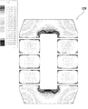
一方、図23乃至図28は、上述したように、本実施形態において、パラメータとしての寸法Wmを変化させた実施例1及び変形例1乃至5に係るリアクトル部品のコアを設計し、それぞれの磁束分布状態をシュミレーションにより観測した結果、対応するコアの磁束分布状態を示す図である。
23 to 28, on the other hand, as described above, in this embodiment, the cores of the reactor parts according to Example 1 and
図23乃至図28においては、上述したように磁性体のブロック123aの寸法Wmを、Wm=Wb×1(実施例1)、Wm=Wb×0.25(変形例1)、Wm=Wb×0.5(変形例2)、Wm=Wb×0.75(変形例3)、Wm=Wb×1.25(変形例4)、Wm=Wb×1.425(変形例5)というように変えたコア129を用いたリアクトル部品のコアについて、定格使用時におけるコアの磁束分布状態が色分けにより示されている。
23 to 28, as described above, the dimension Wm of the
特に、図23から明瞭なように、実施例1のコアで、磁気飽和も無く、最もバランスの良い磁束分布状態を示している。また、図24乃至図28からも分かるように、変形例1乃至5のコアでも、磁気飽和が限界に達している箇所は見られず、十分に使用可能な磁束分布状態を示していることを確認できた。 In particular, as is clear from FIG. 23, the core of Example 1 shows no magnetic saturation and the most balanced magnetic flux distribution state. Further, as can be seen from FIGS. 24 to 28, even in the cores of the modified examples 1 to 5, no magnetic saturation has reached the limit, indicating that a sufficiently usable magnetic flux distribution state is shown. It could be confirmed.
以上に述べたように、本発明の第4の実施形態によれば、非巻回部を2つの略台形又は略三角形の平面形状を有する磁性体ブロックにより形成し、巻回部を構成する磁性体ブロックをそれぞれの略台形又は略三角形の底部側で挟んで対向して配置し、非巻回部を構成する2個の磁性体のブロック123aの頂部における磁路と直交する方向の断面積を巻回部を構成する2個の磁性体のブロック123bの磁路と直交する方向の断面積に対して小さくしたので、上述した第1乃至第3の実施形態に比べて、殆ど磁束の通らない部分を更に削減して更なる低コスト化・小型化・軽量化が可能となる。
As described above, according to the fourth embodiment of the present invention, the non-winding part is formed of two magnetic blocks having a substantially trapezoidal or substantially triangular planar shape, and the magnetic material constituting the winding part. The body blocks are arranged to face each other on the bottom side of each substantially trapezoidal or substantially triangular shape, and the cross-sectional area in the direction perpendicular to the magnetic path at the top of the
尚、本発明の第4の実施形態は、圧粉(ダスト)コアなら、略台形又は略三角形の型を作って粉を入れ加圧すれば良いので製作が簡単である。このため、低コスト化の点では圧粉(ダスト)コアで高い効果が得られる。但し、小型化・軽量化の点では圧粉コアでも積層(ラミネーション)コアでも同じように高い効果が得られるのは勿論である。 In the fourth embodiment of the present invention, if a dust core is used, a substantially trapezoidal or substantially triangular mold may be formed, and powder may be added and pressurized, so that the production is simple. For this reason, in the point of cost reduction, a high effect is acquired with a dust (dust) core. However, it is a matter of course that the same high effect can be obtained in both the dust core and the laminated core in terms of size reduction and weight reduction.
尚、本発明の第4の実施形態のコアも、図2に示したのと同様の熱伝導性ケース1に収納されて用いられる。この場合、本発明の第4の実施形態のリアクトル部品のコアでは、非巻回部が略台形又は略三角形の平面形状を有する磁性体ブロックにより形成されているので、U字型のコアのようなラウンド状の角部が無いことで、熱伝導性ケース1に押し付けられる面が増えるので、放熱性が向上する。また、U字型のコアのラウンド状の角部が無く、リアクトル部品のコアの角部が平面で構成されているので、ケース内のデッドスペースが減少し、スペース効率も向上する。
In addition, the core of the 4th Embodiment of this invention is also accommodated and used for the heat
尚、上述した第1、第2及び第4の実施形態におけるコアは磁気ギャップを含む8分割型、第3の実施形態におけるコアは磁気ギャップを含む4分割型に構成されているが、本発明は、分割されていない一体型のコアにも適用可能である。また、例えば、図1に示した従来例の6分割型のコア等、4分割、8分割以外の分割数による分割型のコアにも勿論適用可能である。但し、第1及び第3の実施形態におけるインダクタンス値の測定結果等からも、分割数が多い程、コアの非巻回部の磁路と直交する方向の断面積の削減量を多くすることができるものと考えられる。 The core in the first, second, and fourth embodiments described above is configured as an eight-divided type including a magnetic gap, and the core in the third embodiment is configured as a four-divided type including a magnetic gap. Can be applied to an integral core that is not divided. Further, for example, the present invention can also be applied to a split-type core having a number of divisions other than four divisions and eight divisions, such as the conventional six-division core shown in FIG. However, also from the measurement results of the inductance values in the first and third embodiments, as the number of divisions increases, the amount of reduction in the cross-sectional area in the direction orthogonal to the magnetic path of the unwinding portion of the core can be increased. It is considered possible.
以上、本発明について実施の形態をもとに説明したが、本発明は上記実施形態に限定されるものではなく、特許請求の範囲の要旨を逸脱しない範囲で種々変更することができる。 While the present invention has been described based on the embodiments, the present invention is not limited to the above-described embodiments, and various modifications can be made without departing from the scope of the claims.
本発明は、少なくとも、巻線と磁性体のコアを備え、当該コアは巻線が巻回される巻回部と巻線が巻回されない非巻回部とを含み、巻回部に巻線が巻回されて形成されるリアクトル部品のコアであれば、広く適用可能である。 The present invention includes at least a winding and a magnetic core, and the core includes a winding portion around which the winding is wound and a non-winding portion around which the winding is not wound. If it is the core of the reactor component formed by being wound, it is widely applicable.
1 熱伝導性ケース、 2 巻線、 3a、3b、103a、103b、113a、113b 、123a、123b 磁性体のブロック、 4 ボビン、 6、106 シート材、 7 絶縁シート、 8 充填材、 10 リアクトル、Wa、W1a、W2a、W3a、WCa、W3Ca、Wb コア(ブロック)幅、 Ha、Hb コア(ブロック)高さ、 9、109、119、129 コア
1 thermal conductive case, 2 windings, 3a, 3b, 103a, 103b, 113a, 113b, 123a, 123b magnetic block, 4 bobbin, 6, 106 sheet material, 7 insulating sheet, 8 filler, 10 reactor, Wa, W1a, W2a, W3a, WCa, W3Ca, Wb Core (block) width, Ha, Hb Core (block) height, 9, 109, 119, 129 core
Claims (5)
前記コアの非巻回部の磁路と直交する方向の断面積を前記巻回部の磁路と直交する方向の断面積に対して小さくしたことを特徴とするリアクトル部品。 At least a winding and a magnetic core are provided, and the core includes a winding portion around which the winding is wound, and a non-winding portion around which the winding is not wound. In the reactor part formed by winding the wire,
A reactor part, wherein a cross-sectional area in a direction orthogonal to a magnetic path of a non-winding portion of the core is made smaller than a cross-sectional area in a direction orthogonal to the magnetic path of the winding portion.
The reactor component according to claim 1, wherein the reactor component is used for an on-vehicle reactor.
Priority Applications (7)
| Application Number | Priority Date | Filing Date | Title |
|---|---|---|---|
| JP2006211499A JP4751266B2 (en) | 2006-02-09 | 2006-08-02 | Reactor parts |
| KR1020087019895A KR101132097B1 (en) | 2006-02-09 | 2007-02-06 | Reactor part |
| DE112007000344.8T DE112007000344B4 (en) | 2006-02-09 | 2007-02-06 | choke part |
| CN2007800051228A CN101385101B (en) | 2006-02-09 | 2007-02-06 | Reactor part |
| US12/223,618 US7782168B2 (en) | 2006-02-09 | 2007-02-06 | Reactor part |
| PCT/JP2007/000059 WO2007091388A1 (en) | 2006-02-09 | 2007-02-06 | Reactor part |
| US12/662,804 US8427271B2 (en) | 2006-02-09 | 2010-05-04 | Reactor part |
Applications Claiming Priority (3)
| Application Number | Priority Date | Filing Date | Title |
|---|---|---|---|
| JP2006033079 | 2006-02-09 | ||
| JP2006033079 | 2006-02-09 | ||
| JP2006211499A JP4751266B2 (en) | 2006-02-09 | 2006-08-02 | Reactor parts |
Publications (2)
| Publication Number | Publication Date |
|---|---|
| JP2007243136A true JP2007243136A (en) | 2007-09-20 |
| JP4751266B2 JP4751266B2 (en) | 2011-08-17 |
Family
ID=38344995
Family Applications (1)
| Application Number | Title | Priority Date | Filing Date |
|---|---|---|---|
| JP2006211499A Active JP4751266B2 (en) | 2006-02-09 | 2006-08-02 | Reactor parts |
Country Status (6)
| Country | Link |
|---|---|
| US (2) | US7782168B2 (en) |
| JP (1) | JP4751266B2 (en) |
| KR (1) | KR101132097B1 (en) |
| CN (1) | CN101385101B (en) |
| DE (1) | DE112007000344B4 (en) |
| WO (1) | WO2007091388A1 (en) |
Cited By (6)
| Publication number | Priority date | Publication date | Assignee | Title |
|---|---|---|---|---|
| JP2009177012A (en) * | 2008-01-25 | 2009-08-06 | West Japan Railway Co | Dc reactor |
| JP2013229527A (en) * | 2012-04-27 | 2013-11-07 | Nec Tokin Corp | Reactor |
| JP2015008236A (en) * | 2013-06-26 | 2015-01-15 | Jfeスチール株式会社 | Reactor |
| EP2889884A2 (en) | 2013-12-19 | 2015-07-01 | Sumida Corporation | Coil component, method of manufacturing coil component, and coil component set |
| JP2015135845A (en) * | 2014-01-16 | 2015-07-27 | Jfeスチール株式会社 | On-vehicle reactor |
| JP2018181985A (en) * | 2017-04-07 | 2018-11-15 | スミダコーポレーション株式会社 | Core for coil parts and coil parts |
Families Citing this family (40)
| Publication number | Priority date | Publication date | Assignee | Title |
|---|---|---|---|---|
| JP4751266B2 (en) * | 2006-02-09 | 2011-08-17 | 株式会社タムラ製作所 | Reactor parts |
| JP4465635B2 (en) * | 2008-03-17 | 2010-05-19 | トヨタ自動車株式会社 | Reactor device |
| ATE523887T1 (en) * | 2008-05-13 | 2011-09-15 | Abb Technology Ag | MODULAR TOIR CORE |
| JP4998381B2 (en) * | 2008-06-16 | 2012-08-15 | 住友電気工業株式会社 | Reactor and converter |
| US7830236B2 (en) | 2008-09-09 | 2010-11-09 | Gm Global Technology Operations, Inc. | DC-DC converter for fuel cell application using hybrid inductor core material |
| WO2010057535A1 (en) * | 2008-11-24 | 2010-05-27 | Abb Technology Ag | An induction device |
| JP4834201B2 (en) * | 2009-03-05 | 2011-12-14 | 株式会社タムラ製作所 | Sensor element fixing structure with leads |
| WO2011013394A1 (en) * | 2009-07-29 | 2011-02-03 | 住友電気工業株式会社 | Reactor |
| JP5656063B2 (en) * | 2009-10-29 | 2015-01-21 | 住友電気工業株式会社 | Reactor |
| JP5465151B2 (en) * | 2010-04-23 | 2014-04-09 | 住友電装株式会社 | Reactor |
| KR100978503B1 (en) * | 2010-04-23 | 2010-08-31 | 주식회사 시스하이텍 | Slim type high voltage transformer |
| US8466765B2 (en) * | 2010-10-20 | 2013-06-18 | Astec International Limited | Core and coil construction for multi-winding magnetic structures |
| JP5179561B2 (en) * | 2010-12-02 | 2013-04-10 | 三菱電機株式会社 | Reactor device |
| WO2012073246A1 (en) * | 2010-12-02 | 2012-06-07 | D. M. Benatav Ltd. | Magnetic core, methods of designing and constructing thereof and devices including same |
| TW201225118A (en) * | 2010-12-06 | 2012-06-16 | Delta Electronics Thailand Public Co Ltd | Magnetic device and assembling method thereof |
| WO2012111153A1 (en) * | 2011-02-18 | 2012-08-23 | トヨタ自動車株式会社 | Reactor |
| JP5958877B2 (en) * | 2011-02-25 | 2016-08-02 | 住友電気工業株式会社 | Reactor, converter, and power converter |
| JP6127365B2 (en) * | 2011-04-28 | 2017-05-17 | 住友電気工業株式会社 | Reactor, composite material, reactor core, converter, and power converter |
| JP5120679B1 (en) * | 2011-05-10 | 2013-01-16 | 住友電気工業株式会社 | Reactor |
| JP5120678B2 (en) | 2011-05-10 | 2013-01-16 | 住友電気工業株式会社 | Reactor |
| CN103688323A (en) * | 2011-07-20 | 2014-03-26 | 丰田自动车株式会社 | Reactor |
| JP5032690B1 (en) * | 2011-07-27 | 2012-09-26 | 住友電気工業株式会社 | Compacted body |
| JP2013051288A (en) * | 2011-08-30 | 2013-03-14 | Tdk Corp | Reactor and electric apparatus |
| JP6024878B2 (en) * | 2011-10-06 | 2016-11-16 | 住友電気工業株式会社 | Reactor, coil component for reactor, converter, and power converter |
| DE102011116246B4 (en) * | 2011-10-18 | 2014-07-10 | Audi Ag | Secondary transformer unit for attachment to an electric and electric vehicle |
| CN102360863B (en) * | 2011-11-08 | 2013-10-16 | 田村(中国)企业管理有限公司 | Magnetic integrated double inductor |
| CN102436907B (en) * | 2011-12-22 | 2014-01-01 | 广州金升阳科技有限公司 | Magnetic core for transformer |
| JP5964619B2 (en) * | 2012-03-15 | 2016-08-03 | 株式会社タムラ製作所 | Reactor and reactor manufacturing method |
| JP5900741B2 (en) * | 2012-03-30 | 2016-04-06 | 日立金属株式会社 | Composite magnetic core, reactor and power supply |
| JP5322041B2 (en) * | 2012-05-10 | 2013-10-23 | 住友電気工業株式会社 | Reactor and converter |
| US9343223B2 (en) * | 2013-03-29 | 2016-05-17 | Tamura Corporation | Reactor |
| JP5516923B2 (en) * | 2013-07-19 | 2014-06-11 | 住友電気工業株式会社 | Reactor and converter |
| CA2953541C (en) * | 2014-07-11 | 2023-01-31 | Sony Corporation | Information processing device, information processing method, and program |
| JP6160605B2 (en) * | 2014-12-24 | 2017-07-12 | トヨタ自動車株式会社 | Reactor |
| US20180040408A1 (en) * | 2015-04-07 | 2018-02-08 | Panasonic Intellectual Prpoerty Management Co., Ltd. | Reactor |
| RU176199U1 (en) * | 2017-08-08 | 2018-01-12 | Общество с ограниченной ответственностью "ЭНСОНС" | ARC EXTINGUISHING REACTOR |
| JP7191535B2 (en) * | 2018-03-29 | 2022-12-19 | 株式会社小松製作所 | REACTOR CORE, REACTOR AND METHOD FOR MANUFACTURING REACTOR CORE |
| WO2021092106A1 (en) * | 2019-11-07 | 2021-05-14 | Hyperloop Technologies, Inc. | A force-producing electromagnetic machine |
| JP7331770B2 (en) * | 2020-04-30 | 2023-08-23 | トヨタ自動車株式会社 | REACTOR MANUFACTURING METHOD AND REACTOR |
| JP7603429B2 (en) | 2020-12-04 | 2024-12-20 | 株式会社タムラ製作所 | Reactor |
Citations (6)
| Publication number | Priority date | Publication date | Assignee | Title |
|---|---|---|---|---|
| JPH0722258A (en) * | 1993-06-30 | 1995-01-24 | Matsushita Electric Ind Co Ltd | Reactor and manufacturing method thereof |
| JPH11273885A (en) * | 1998-03-24 | 1999-10-08 | Stanley Electric Co Ltd | Discharge lamp lighting device |
| JP2003047241A (en) * | 2001-07-31 | 2003-02-14 | Matsushita Electric Ind Co Ltd | Switching power supply |
| JP2004327569A (en) * | 2003-04-23 | 2004-11-18 | Toyota Motor Corp | Reactor device |
| JP2005050918A (en) * | 2003-07-30 | 2005-02-24 | Toyota Central Res & Dev Lab Inc | Reactor, reactor core and manufacturing method thereof |
| JP2005150517A (en) * | 2003-11-18 | 2005-06-09 | Toyota Motor Corp | VOLTAGE CONVERTER, LOAD DRIVE DEVICE HAVING THE SAME, AND VEHICLE |
Family Cites Families (30)
| Publication number | Priority date | Publication date | Assignee | Title |
|---|---|---|---|---|
| US1644729A (en) * | 1922-02-21 | 1927-10-11 | Gen Electric | Stationary induction apparatus |
| US2149634A (en) * | 1936-09-10 | 1939-03-07 | Jr Edmund O Schweitzer | Transformer fault indicating means |
| US2762988A (en) * | 1951-05-25 | 1956-09-11 | Harnischfeger Corp | Magnetic core assembly |
| US2849696A (en) * | 1953-08-04 | 1958-08-26 | M & F Associates | Ferromagnetic core |
| US2916560A (en) * | 1955-07-30 | 1959-12-08 | Mathez Robert | Sound head of a magnetic tape recorder |
| GB1080475A (en) * | 1966-06-13 | 1967-08-23 | British Lighting Ind Ltd | A choke having a winding of foil |
| US3593243A (en) * | 1969-06-02 | 1971-07-13 | High Voltage Power Corp | Electrical induction apparatus |
| US4369476A (en) | 1980-07-25 | 1983-01-18 | The Perkin-Elmer Corporation | Multi-track recording head assembly with electromagnetic cross-talk neutralization |
| US4447795A (en) * | 1981-05-05 | 1984-05-08 | The United States Of America As Represented By The United States Department Of Energy | Laminated grid and web magnetic cores |
| US4800356A (en) | 1987-12-01 | 1989-01-24 | Eaton Corporation | Shunt transformer |
| DE4040491C2 (en) * | 1989-12-18 | 1996-12-19 | Mitsubishi Electric Corp | Magnetic head device |
| DE69120986T2 (en) * | 1990-02-27 | 1996-12-12 | Tdk Corp | Coil arrangement |
| AU4536197A (en) | 1996-12-12 | 1998-06-25 | J.E. Thomas Specialties Limited | RF power coil or choke for separating RF and AC in a CATV or similar system |
| DE19934767A1 (en) * | 1999-07-23 | 2001-01-25 | Philips Corp Intellectual Pty | Magnetic component |
| US6885273B2 (en) * | 2000-03-30 | 2005-04-26 | Abb Ab | Induction devices with distributed air gaps |
| WO2001075911A1 (en) | 2000-04-03 | 2001-10-11 | Abb Ab | A multiphase induction device |
| JP3398820B2 (en) * | 2000-07-28 | 2003-04-21 | ミネベア株式会社 | Reactor |
| WO2002033711A1 (en) * | 2000-10-18 | 2002-04-25 | Koninklijke Philips Electronics N.V. | Inductor arrangement |
| JP2003124039A (en) | 2001-10-10 | 2003-04-25 | Toyota Motor Corp | Reactor |
| US6822549B2 (en) * | 2001-12-03 | 2004-11-23 | Wolfgram Industries, Inc. | Method for increased coupling coefficient in a pulse type transformer through coil configuration and varied core area |
| EP1341191A1 (en) | 2002-02-27 | 2003-09-03 | NEC TOKIN Corporation | Powder core and reactor using the same |
| US20050258927A1 (en) | 2002-07-17 | 2005-11-24 | Weimin Lu | Simplified harmonic-free constant-voltage transformer |
| JP2004111528A (en) * | 2002-09-17 | 2004-04-08 | Matsushita Electric Ind Co Ltd | Step-up transformer for magnetron drive |
| WO2004040599A1 (en) | 2002-10-31 | 2004-05-13 | Delta Energy Systems (Switzerland) Ag | A circuit board with a planar magnetic element |
| US7317374B2 (en) * | 2003-01-03 | 2008-01-08 | Nucore, Inc. | Self-damped inductor |
| US6856230B2 (en) * | 2003-05-27 | 2005-02-15 | Weimin Lu | Harmonic filtering circuit with special transformer |
| JP2005310988A (en) | 2004-04-20 | 2005-11-04 | Denso Corp | Method for assembling reactor or transformer |
| DE202005017998U1 (en) * | 2004-11-16 | 2006-07-20 | JUNG FONG ELECTRONICS CO., LTD., Shen Ken Hsiang | Electrical component with the effect of a variable air gap |
| JP4751266B2 (en) * | 2006-02-09 | 2011-08-17 | 株式会社タムラ製作所 | Reactor parts |
| JP4348381B2 (en) * | 2007-05-30 | 2009-10-21 | 富士通株式会社 | Image encryption / decryption device, method and program |
-
2006
- 2006-08-02 JP JP2006211499A patent/JP4751266B2/en active Active
-
2007
- 2007-02-06 DE DE112007000344.8T patent/DE112007000344B4/en active Active
- 2007-02-06 KR KR1020087019895A patent/KR101132097B1/en active Active
- 2007-02-06 US US12/223,618 patent/US7782168B2/en active Active
- 2007-02-06 WO PCT/JP2007/000059 patent/WO2007091388A1/en not_active Ceased
- 2007-02-06 CN CN2007800051228A patent/CN101385101B/en active Active
-
2010
- 2010-05-04 US US12/662,804 patent/US8427271B2/en active Active
Patent Citations (6)
| Publication number | Priority date | Publication date | Assignee | Title |
|---|---|---|---|---|
| JPH0722258A (en) * | 1993-06-30 | 1995-01-24 | Matsushita Electric Ind Co Ltd | Reactor and manufacturing method thereof |
| JPH11273885A (en) * | 1998-03-24 | 1999-10-08 | Stanley Electric Co Ltd | Discharge lamp lighting device |
| JP2003047241A (en) * | 2001-07-31 | 2003-02-14 | Matsushita Electric Ind Co Ltd | Switching power supply |
| JP2004327569A (en) * | 2003-04-23 | 2004-11-18 | Toyota Motor Corp | Reactor device |
| JP2005050918A (en) * | 2003-07-30 | 2005-02-24 | Toyota Central Res & Dev Lab Inc | Reactor, reactor core and manufacturing method thereof |
| JP2005150517A (en) * | 2003-11-18 | 2005-06-09 | Toyota Motor Corp | VOLTAGE CONVERTER, LOAD DRIVE DEVICE HAVING THE SAME, AND VEHICLE |
Cited By (7)
| Publication number | Priority date | Publication date | Assignee | Title |
|---|---|---|---|---|
| JP2009177012A (en) * | 2008-01-25 | 2009-08-06 | West Japan Railway Co | Dc reactor |
| JP2013229527A (en) * | 2012-04-27 | 2013-11-07 | Nec Tokin Corp | Reactor |
| JP2015008236A (en) * | 2013-06-26 | 2015-01-15 | Jfeスチール株式会社 | Reactor |
| EP2889884A2 (en) | 2013-12-19 | 2015-07-01 | Sumida Corporation | Coil component, method of manufacturing coil component, and coil component set |
| JP2015135845A (en) * | 2014-01-16 | 2015-07-27 | Jfeスチール株式会社 | On-vehicle reactor |
| JP2018181985A (en) * | 2017-04-07 | 2018-11-15 | スミダコーポレーション株式会社 | Core for coil parts and coil parts |
| JP7176174B2 (en) | 2017-04-07 | 2022-11-22 | スミダコーポレーション株式会社 | Core for coil parts and coil parts |
Also Published As
| Publication number | Publication date |
|---|---|
| US8427271B2 (en) | 2013-04-23 |
| WO2007091388A1 (en) | 2007-08-16 |
| DE112007000344T5 (en) | 2009-07-02 |
| US7782168B2 (en) | 2010-08-24 |
| JP4751266B2 (en) | 2011-08-17 |
| US20090027151A1 (en) | 2009-01-29 |
| CN101385101B (en) | 2011-09-21 |
| US20110169598A1 (en) | 2011-07-14 |
| KR101132097B1 (en) | 2012-04-04 |
| CN101385101A (en) | 2009-03-11 |
| KR20080103526A (en) | 2008-11-27 |
| DE112007000344B4 (en) | 2022-12-01 |
Similar Documents
| Publication | Publication Date | Title |
|---|---|---|
| JP4751266B2 (en) | Reactor parts | |
| JP4482477B2 (en) | Combined reactor winding structure | |
| US6750749B2 (en) | Amorphous metal core transformer | |
| KR101259778B1 (en) | Three-phase high frequency transformer | |
| US12095325B2 (en) | Stator and motor using same | |
| US6593837B2 (en) | Transformer apparatus | |
| JP6490355B2 (en) | Reactor parts and reactors | |
| JP5399317B2 (en) | Reactor | |
| JP2008103371A (en) | Transformer | |
| JP6075678B2 (en) | Composite magnetic core, reactor and power supply | |
| JP2004040871A (en) | Stator core and motor | |
| JP7040928B2 (en) | Inductor | |
| US20180040408A1 (en) | Reactor | |
| JP2001257120A (en) | Multiple tubular choke coil. | |
| JP2013197570A (en) | Composite magnetic core, reactor, and power supply device | |
| JP2022089288A (en) | Reactor | |
| JP2005079546A (en) | Low-height coil component | |
| KR20210051619A (en) | Asymmetric core for transformer | |
| JP2000100639A (en) | Reactor | |
| JP2003031422A (en) | Coil component | |
| JP2000331837A (en) | Coil component | |
| JP2007335569A (en) | Ignition coil for internal combustion engine | |
| TW201106390A (en) | Surface mount magnetic components and methods of manufacturing the same | |
| KR20010000965A (en) | Ballasts for fluorescent lamps |
Legal Events
| Date | Code | Title | Description |
|---|---|---|---|
| A621 | Written request for application examination |
Free format text: JAPANESE INTERMEDIATE CODE: A621 Effective date: 20071030 |
|
| A131 | Notification of reasons for refusal |
Free format text: JAPANESE INTERMEDIATE CODE: A131 Effective date: 20100706 |
|
| A521 | Request for written amendment filed |
Free format text: JAPANESE INTERMEDIATE CODE: A523 Effective date: 20100906 |
|
| TRDD | Decision of grant or rejection written | ||
| A01 | Written decision to grant a patent or to grant a registration (utility model) |
Free format text: JAPANESE INTERMEDIATE CODE: A01 Effective date: 20110517 |
|
| A01 | Written decision to grant a patent or to grant a registration (utility model) |
Free format text: JAPANESE INTERMEDIATE CODE: A01 |
|
| A61 | First payment of annual fees (during grant procedure) |
Free format text: JAPANESE INTERMEDIATE CODE: A61 Effective date: 20110520 |
|
| R150 | Certificate of patent or registration of utility model |
Ref document number: 4751266 Country of ref document: JP Free format text: JAPANESE INTERMEDIATE CODE: R150 Free format text: JAPANESE INTERMEDIATE CODE: R150 |
|
| FPAY | Renewal fee payment (event date is renewal date of database) |
Free format text: PAYMENT UNTIL: 20140527 Year of fee payment: 3 |