JP2007239840A - Anticorrosion structure of pipe-end face - Google Patents
Anticorrosion structure of pipe-end face Download PDFInfo
- Publication number
- JP2007239840A JP2007239840A JP2006061947A JP2006061947A JP2007239840A JP 2007239840 A JP2007239840 A JP 2007239840A JP 2006061947 A JP2006061947 A JP 2006061947A JP 2006061947 A JP2006061947 A JP 2006061947A JP 2007239840 A JP2007239840 A JP 2007239840A
- Authority
- JP
- Japan
- Prior art keywords
- pipe
- cap
- tube
- face
- anticorrosion
- Prior art date
- Legal status (The legal status is an assumption and is not a legal conclusion. Google has not performed a legal analysis and makes no representation as to the accuracy of the status listed.)
- Granted
Links
Images


Abstract
Description
本発明は管端面の防食構造に関し、特に、鋳鉄製の管路の敷設現場で切管を行なった場合などに適用することができる管端面の防食構造に関する。 The present invention relates to a pipe end face anticorrosion structure, and more particularly, to a pipe end face anticorrosion structure that can be applied to a case where a cut pipe is cut at a site where a cast iron pipe line is laid.
近年、上水道などの鋳鉄製の管路において、継手部に耐震性能を有しない管路から、継手部に耐震性能を有した管路への敷設替えが行なわれることが多い。耐震性能を有する管路における管どうしの継手部は、この継手部を構成する一方の管の受口の内部に挿入される他方の管の挿口の先端の外周に、この挿口が受口から抜け出すのを防止するための突部が形成されることが通例である。 In recent years, pipes made of cast iron such as waterworks are often replaced with pipes that do not have seismic performance at the joints to pipes that have seismic performance at the joints. The joint part of the pipes in the pipe having the seismic performance is connected to the outer periphery of the distal end of the insertion part of the other pipe inserted into the inside of the reception part of one pipe constituting the joint part. It is customary that a protrusion is formed to prevent it from slipping out.
一方、このような耐震機能を有する管路を敷設する場合において、配管施工現場では、敷設する管路の長さの都合上、管を所定の長さに切断することがある。たとえば、管路に沿った所定の場所にバルブを設置する場合は、このバルブに接続される直管を、このバルブの設置位置に対応させて切断することがある。このような工事は切管と称される。 On the other hand, when laying a pipeline having such an earthquake-resistant function, the pipe may be cut to a predetermined length on the piping construction site due to the length of the pipeline to be laid. For example, when a valve is installed at a predetermined location along a pipeline, a straight pipe connected to the valve may be cut in correspondence with the installation position of the valve. Such construction is called a cut tube.
鋳鉄製の管は一般に内外面および端面を塗装するなどによりその防食が図られているが、この管に切管を施すと、切断された部分の端面に管の金属の地肌が露出する。このため、この露出部に新たに防食を施すことが必要になる。 Cast iron pipes are generally anticorrosive by painting their inner and outer surfaces and end faces. However, when a cut pipe is applied to the pipe, the metal ground of the pipe is exposed at the end face of the cut portion. For this reason, it is necessary to newly apply corrosion protection to the exposed portion.
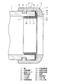
特許文献1には、このような場合における防食構造の例が記載されている。図8は、この特許文献1に記載された防食構造を示すものである。ここで1は鋳鉄製の管であり、内外面に塗装が施されているが、配管施工現場で切管されることによって、その切断端面2では金属の地肌が露出している。切断端面2を含む管1の端部には防食キャップ3が被せられ、さらにこの防食キャップ3を含む管1の端部には、管1の端部の外周に環状突部4を形成するための鋳鉄製のリング体5が装着されている。
Patent Document 1 describes an example of the anticorrosion structure in such a case. FIG. 8 shows the anticorrosion structure described in Patent Document 1. Here, reference numeral 1 denotes a cast iron pipe, which is coated on the inner and outer surfaces, but the
防食キャップ3はゴムなどの弾性材料にて形成されており、横断面がアラビア数字の「7」の形に形成されて、切断断面2に密接してこの切断端面2を覆うつば部6と、管1の端部の内周面7に密接する内面接触部8と、管1の端部の外周面9に密接する外面接触部10とを一体に有する。防食キャップ3は、管1の端部に装着される前は、特につば部6と内面接触部8とがなす角が、90度よりも狭い鋭角に形成されている。そして、管1の端部に装着されることでこの鋭角の部分が弾性的に拡げられ、そのときに防食キャップ3に発生する弾性力によって、特につば部6と内面接触部8とが管1の切断端面2と内周面7とに圧接して、上記のような密接した状態を形成可能とされている。
The
防食キャップ3において、内面接触部8は、他の部分よりも厚く形成されて、弾性力による管1の内周面7への圧接力が大きく作用して、管内の水が、防食キャップ3と管1の内周面7との間に、また特につば部6と切断端面2との間に、入り込まないようにされている。内面接触部8は外周突部11を有し、この外周突部11の部分で重点的に管1の内周面7に接するようにして、その面圧を増大させることにより、いっそうの水密性を確保できるようにされている。
In the
リング体5は、たとえば周方向一つ割りに形成されるとともに、管1の端部に外ばめされる突部形成部13と、管1の切断端面2を覆うように配置される前端形成部14とが一体に形成された構成である。突部形成部13には横断面矩形状の内周突部15が一体に形成されており、この内周突部15が、鋳鉄管1の切管の際にこの鋳鉄管1の外周に形成される横断面矩形状の環状溝16にはめ込まれることで、リング体5を所定の位置に位置決めした状態で管1に装着可能である。これによって、管1の先端の外周に環状突部4が形成される。なお、リング体5は、内周突部15が環状溝16にはまり込んだ状態で、タッピンネジなどの適宜の手段により管1に固定される。このとき、防食キャップ3の外面接触部10は、リング体5と管1との間に挟み込まれて圧縮され、これによって、その部分で保持されるとともに、リング体5と管1との間をシールする。
The
上記のように内周突部15が環状溝16にはまり込むことでリング体5が管1に対し位置決めされた状態で、その前端形成部14は、管1に装着された防食キャップ3のつば部6から管軸方向にわずかな隙間をおいた位置に配置され、これによって管1の前端傾斜部を形成可能である。17は前端形成部14の端面で、管軸方向と直角な方向に形成されることで、防食キャップ3のつば部6に向かい合うようにされている。
In the state where the
このような構成によれば、管1の端部が防食キャップ3によって密接状態で覆われ、それによって、管内の水が切断端面2に到達することが防止されて、その防食が図られる。なお、管1を地中に埋設したときの地下水などの管1の周囲の水も、上記のように防食キャップ3の外面接触部10がリング体5と管1との間に圧縮状態で挟み込まれることによって、同様に切断端面2に到達することが防止される。
しかし、このような図8の構成では、特に管内の水流18が高速流や乱流である場合には、防食キャップ3の内面接触部8に、この内面接触部8を管1の内周面7から剥がそうとする方向の力19が作用することがある。すると、極めてまれにではあるが、内面接触部8のシール性能の低下の原因になることがある。しかも、直線状の管1に切管を施す必要があるのは、上述のようにこの管1をバルブに接合したり、あるいは曲がり管などの異形管に接合したりする箇所であることが多く、これらの箇所では乱流が発生しやすいため、何らかの対策を講じておくことが望ましい。
However, in the configuration of FIG. 8, particularly when the water flow 18 in the pipe is a high-speed flow or a turbulent flow, the inner
そこで本発明は、管の端部に被せてその部分の防食を図るための防食キャップが、管内流体の作用による剥がれが生じにくいものであるようにすることを目的とする。 In view of the above, an object of the present invention is to provide an anti-corrosion cap that covers an end portion of a pipe to prevent the corrosion of the portion so that it is difficult to peel off due to the action of fluid in the pipe.
この目的を達成するため本発明は、切断されて端面の地肌が露出している金属管の端部に、弾性体にて形成された防食キャップを被せ、この防食キャップは、前記端面を覆うつば部と、金属管の内面に接する内面接触部と、金属管の外面に接する外面接触部とを有し、前記金属管の端部にリング体を被せ、このリング体は、金属管に外ばめされて金属管の端部の外周に環状突部を形成可能であるとともに金属管の外面との間で防食キャップの外面接触部を挟み込む突部形成部と、金属管の端面を覆う前記防食キャップのつば部から管軸方向に隙間をおいて位置する前端形成部とを有し、前記金属管の端部に保持部材を設け、この保持部材は、防食キャップの内面接触部の内周側に配置されるウエブ部と、前記防食キャップのつば部とリング体の前端形成部との隙間に配置されるフランジ部とを有するようにしたものである。 In order to achieve this object, according to the present invention, an end portion of a metal tube that is cut and has an exposed end surface is covered with an anti-corrosion cap formed of an elastic body, and the anti-corrosion cap is a collar that covers the end surface. And an inner surface contact portion in contact with the inner surface of the metal tube, and an outer surface contact portion in contact with the outer surface of the metal tube, and an end portion of the metal tube is covered with a ring body. And a protrusion forming portion that can form an annular protrusion on the outer periphery of the end portion of the metal tube and sandwiches the outer surface contact portion of the anticorrosion cap between the outer surface of the metal tube and the anticorrosion covering the end surface of the metal tube And a front end forming portion located at a gap in the tube axis direction from the collar portion of the cap, and a holding member is provided at the end of the metal tube, and the holding member is on the inner peripheral side of the inner surface contact portion of the anticorrosion cap The web portion, the collar portion of the anti-corrosion cap and the ring body It is obtained so as to have a flange portion disposed in the gap between the front end forming portion.
本発明によると、防食キャップの内面接触部の内周側に配置されるウエブ部と、防食キャップのつば部とリング体の前端形成部との隙間に配置されるフランジ部とを有した保持部材を金属管の端部に設けたため、防食キャップが保持部材により保持されることになって、この防食キャップの内面接触部に管内流体の作用による剥がれが生じたり、防食キャップのつば部が端面を覆う機能が低下したりすることを防止でき、このため管の切断端面の確実な防食を図ることができる。 According to the present invention, the holding member having the web portion disposed on the inner peripheral side of the inner surface contact portion of the anticorrosion cap, and the flange portion disposed in the gap between the collar portion of the anticorrosion cap and the front end forming portion of the ring body. Since the anticorrosion cap is held by the holding member, the inner surface contact portion of the anticorrosion cap may be peeled off due to the action of the fluid in the pipe, or the collar portion of the anticorrosion cap It is possible to prevent the covering function from deteriorating, and therefore, it is possible to reliably prevent corrosion of the cut end surface of the pipe.
以下、本発明の実施の形態の管端面の防食構造を、図1〜図7にもとづき、図8に示しものと同一の部材には同一の参照番号を付して、詳細に説明する。
図1に示すように、切管を施した鋳鉄製の管1の端部の外周に環状突部4を形成するために、鋳鉄製のリング体5が装着されている。
Hereinafter, the anticorrosion structure of the pipe end face according to the embodiment of the present invention will be described in detail with reference to FIGS. 1 to 7 and the same members as those shown in FIG.
As shown in FIG. 1, a cast
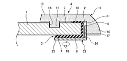
防食キャップ3は、図8に示したものと同様に横断面がアラビア数字の「7」の形に形成されて、切断断面2を覆うつば部6と、管1の端部の内周面7に密接する内面接触部8と、管1の端部の外周面9に密接する外面接触部10とを一体に有する。しかし、内面接触部8は、図8に示すものよりも薄肉に形成されるとともに、図8に示すような外周突部11は有さずにその全面でほぼ均等に管1の内周面7に接するようにされている。防食キャップ3のつば部6とリング体5の前端形成部14の端面17との間には、管軸方向に沿って、隙間21が形成されるように構成されている。
The
管1の端部に、保持部材22が設けられている。この保持部材22は、ステンレス材などによって周方向一つ割りのリング状に形成されるとともに、横断面L字形に形成されて、管1に装着された防食キャップ3の内面接触部8の内周側に配置されるウエブ部23と、防食キャップ3のつば部6とリング体5の前端形成部14との隙間21に配置されるフランジ部24とを、一体に有する。
A
図2(a)に示すように、周方向一つ割りに形成された保持部材22は、管1の端部に装着される前の状態においては、周方向に沿った1箇所に比較的大きめの分割空間25を有した構成とされている。この保持部材22を管1の端部にはめ込む際には、切管後に防食キャップ3が装着されかつリング体5がまだ装着されていない状態の管1の端部に対し、図2(a)に示す状態から分割空間25が縮まるように弾性的に縮径された保持部材22のウエブ部23を挿入し、その後に保持部材22をその弾性力により若干拡径させて、そのウエブ部23を防食キャップ3の内面接触部8の内周に張り付かせる。図2(b)は、そのときの状態を示す。その後に、管1の端部にリング体5を装着する。図1は、そのときの状態を示す。
As shown in FIG. 2 (a), the
このようにすると、保持部材22は、図2(a)に示す場合よりは弾性的に縮径された状態で、すなわち弾性力により広がろうとする状態で、図2(b)および図1に示すように管1の端部に装着される。すると、そのウエブ部23が、管1の内周面7との間で防食キャップ3の内面接触部8を弾性的に挟み込んで保持する。これにより、防食キャップ3の内面接触部8は、管1の内周面7に強く圧接され、その部分をシールして、管1の切断端面2に向けて管内の水が入り込むことを防止する。また、保持部材22のウエブ部23によって防食キャップ3の内面接触部8を管1の内周面7に密接した状態に保持することができるため、管内の水流の作用によって内面接触部8が管1の内周面7から剥がれることを防止できる。よって、切断端面2についての確実な防食が図られることになる。
In this way, the holding
保持部材22のフランジ部24が、リング体5の前端形成部14の端面17と防食キャップ3のつば部6との間の隙間21に配置されているため、このフランジ部24は、ウエブ部23を管軸方向に位置決めし、かつ隙間21を詰めることになる。このため、保持部材22のウエブ部23を所定位置に位置決めできるとともに、管内の水流が作用しても、防食キャップ3のつば部6が切断端面2から大きく浮き上がることにもとづきこのつば部6と内面接触部8とに剥がれが発生することを防止できる。すなわち、図3は管1から出て行く方向に水流18が生じている場合を示すが、この場合は水流18によってウエブ部23が押された状態の保持部材22のフランジ部24がリング体5の前端形成部14の端面17に当たることで、それ以上の変位が防止され、それによって防食キャップ3の剥がれが防止される。
Since the
また図4は、管1に入り込む方向に水流18が生じている場合を示すが、この場合は、水流18によってウエブ部23が押された状態の保持部材22のフランジ部24が防食キャップ3のつば部6を押圧するだけであるので、同様に防食キャップ3の剥がれが防止される。
FIG. 4 shows the case where the
このため、防食キャップ3の内面接触部8に水流18の作用による剥がれが生じたり、防食キャップ3のつば部6が管1の切断端面2を覆う機能の低下が生じたりすることを防止でき、したがって管1の切断端面2の確実な防食を図ることができる。
For this reason, it can prevent that the peeling by the effect | action of the
保持部材22は、横断面L字形の長尺部材を、図2に示すようにC形に湾曲するように曲げ加工することで、安価に形成することができる。この曲げ加工を容易に行なうために、横断面L字形の長尺部材であって、その長さ方向に沿った適当位置に切欠部を形成したものを用いると好ましい。このような長尺部材を用いて形成した保持部材22は、図5に示すようになり、図示のように、保持部材22の周方向に沿った適当位置に切欠部26が配置されることになる。
The holding
あるいは、曲げ加工性をさらに向上させるために、長尺部材における切欠部の数を、上記の場合よりも多数にすることができる。図6は、そのような長尺部材を曲げ加工することにより形成された保持部材22の例を示す。ここでは、各切欠部26は、保持部材22の周方向に沿った多数の位置において、保持部材22の長さ方向に沿った寸法があまり大きくならないようにして、それぞれ形成されている。
Alternatively, in order to further improve the bending workability, the number of notches in the long member can be made larger than in the above case. FIG. 6 shows an example of the holding
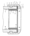
図7は、本発明の他の実施の形態の管端面の防食構造を示す。ここでは、防食キャップ3の内面接触部8に、保持部材22のウエブ部23を納めるための段部27を設けて、この保持部材22のウエブ部23を段部27に納めたときに、防食キャップ3の内面接触部8の内面と保持部材22のウエブ部23の内面とがたとえば面一になるようにされている。このように構成することで、保持部材22のウエブ部23が防食キャップ3の内面接触部8の内面よりも径方向の内側に突出して水流に対する抵抗となることを、防止することができる。なお、段部27を形成することで、防食キャップ3の内面接触部8の先端部は他の部分よりも厚肉となるが、この部分に内周テーパ面28が形成されることで、この厚肉となる部分が水流に対する抵抗となることを防止できる。
FIG. 7 shows an anticorrosion structure for a pipe end surface according to another embodiment of the present invention. Here, when the inner
1 管
2 切断端面
3 防食キャップ
4 環状突部
5 リング体
6 つば部
8 内面接触部
10 外面接触部
13 突部形成部
14 前端形成部
21 隙間
22 保持部材
23 ウエブ部
24 フランジ部
DESCRIPTION OF SYMBOLS 1 Pipe |
Claims (1)
Priority Applications (1)
| Application Number | Priority Date | Filing Date | Title |
|---|---|---|---|
| JP2006061947A JP4845536B2 (en) | 2006-03-08 | 2006-03-08 | Anti-corrosion structure of pipe end face |
Applications Claiming Priority (1)
| Application Number | Priority Date | Filing Date | Title |
|---|---|---|---|
| JP2006061947A JP4845536B2 (en) | 2006-03-08 | 2006-03-08 | Anti-corrosion structure of pipe end face |
Publications (2)
| Publication Number | Publication Date |
|---|---|
| JP2007239840A true JP2007239840A (en) | 2007-09-20 |
| JP4845536B2 JP4845536B2 (en) | 2011-12-28 |
Family
ID=38585584
Family Applications (1)
| Application Number | Title | Priority Date | Filing Date |
|---|---|---|---|
| JP2006061947A Active JP4845536B2 (en) | 2006-03-08 | 2006-03-08 | Anti-corrosion structure of pipe end face |
Country Status (1)
| Country | Link |
|---|---|
| JP (1) | JP4845536B2 (en) |
Cited By (4)
| Publication number | Priority date | Publication date | Assignee | Title |
|---|---|---|---|---|
| JP2011106631A (en) * | 2009-11-20 | 2011-06-02 | Cosmo Koki Co Ltd | Rust preventing method in cutting plane of existing fluid pipe |
| JP2012145158A (en) * | 2011-01-11 | 2012-08-02 | Cosmo Koki Co Ltd | Anti-rust member |
| JP2012189100A (en) * | 2011-03-09 | 2012-10-04 | Kurimoto Ltd | Tool for mounting stationary ring |
| JP2014095400A (en) * | 2012-11-07 | 2014-05-22 | Cosmo Koki Co Ltd | Blocked processing device |
Citations (2)
| Publication number | Priority date | Publication date | Assignee | Title |
|---|---|---|---|---|
| JPH1078181A (en) * | 1996-09-05 | 1998-03-24 | Taiheiyo Tokushu Chuzo Kk | Anticorrosive fitting |
| JP2005248971A (en) * | 2004-03-01 | 2005-09-15 | Kubota Corp | Corrosion-preventive structure of pipe-end face |
-
2006
- 2006-03-08 JP JP2006061947A patent/JP4845536B2/en active Active
Patent Citations (2)
| Publication number | Priority date | Publication date | Assignee | Title |
|---|---|---|---|---|
| JPH1078181A (en) * | 1996-09-05 | 1998-03-24 | Taiheiyo Tokushu Chuzo Kk | Anticorrosive fitting |
| JP2005248971A (en) * | 2004-03-01 | 2005-09-15 | Kubota Corp | Corrosion-preventive structure of pipe-end face |
Cited By (4)
| Publication number | Priority date | Publication date | Assignee | Title |
|---|---|---|---|---|
| JP2011106631A (en) * | 2009-11-20 | 2011-06-02 | Cosmo Koki Co Ltd | Rust preventing method in cutting plane of existing fluid pipe |
| JP2012145158A (en) * | 2011-01-11 | 2012-08-02 | Cosmo Koki Co Ltd | Anti-rust member |
| JP2012189100A (en) * | 2011-03-09 | 2012-10-04 | Kurimoto Ltd | Tool for mounting stationary ring |
| JP2014095400A (en) * | 2012-11-07 | 2014-05-22 | Cosmo Koki Co Ltd | Blocked processing device |
Also Published As
| Publication number | Publication date |
|---|---|
| JP4845536B2 (en) | 2011-12-28 |
Similar Documents
| Publication | Publication Date | Title |
|---|---|---|
| JP5019971B2 (en) | Pipe fitting | |
| JP4845536B2 (en) | Anti-corrosion structure of pipe end face | |
| JP5080151B2 (en) | Pipe fitting | |
| JP5019963B2 (en) | Pipe fitting | |
| JP4352179B2 (en) | Resin pipe joint | |
| JP4986688B2 (en) | Pipe joint and pipe overvoltage protection method | |
| JP2005351428A (en) | Corrosion prevention structure of pipe end face | |
| JPH07253189A (en) | Corrosion preventive cap for pipe end face | |
| JP3855170B2 (en) | Water pipe fitting device | |
| JP4458934B2 (en) | Anti-corrosion structure of pipe end face | |
| JP7170468B2 (en) | Pipe joint structure for sewage pipes | |
| JP3764323B2 (en) | Plug-in type propulsion pipe | |
| JP5702104B2 (en) | Insulation joint | |
| US20070200341A1 (en) | Sewer tap with watertight lip | |
| JP2005248971A (en) | Corrosion-preventive structure of pipe-end face | |
| JP2005030503A (en) | Snap tap | |
| JPH0313674Y2 (en) | ||
| JP5723160B2 (en) | Rust prevention member | |
| JP3993911B2 (en) | Connection structure between corrosion-resistant pipe and corrosion-resistant pipe joint | |
| JP4668018B2 (en) | Dustproof cap with anti-corrosion sleeve for saddle faucet and saddle faucet | |
| JP2007205443A (en) | Corrosion prevention means for pipe end part | |
| JP2011140971A (en) | Pipe end corrosion preventive structure | |
| JP2007330303A (en) | Connecting structure of flexible tube for sprinkler | |
| JP4610963B2 (en) | Temporary assembly structure of anti-corrosion sleeve | |
| JP5368739B2 (en) | Piping connection structure and connection method |
Legal Events
| Date | Code | Title | Description |
|---|---|---|---|
| RD04 | Notification of resignation of power of attorney |
Free format text: JAPANESE INTERMEDIATE CODE: A7424 Effective date: 20080430 |
|
| A621 | Written request for application examination |
Free format text: JAPANESE INTERMEDIATE CODE: A621 Effective date: 20090227 |
|
| A977 | Report on retrieval |
Free format text: JAPANESE INTERMEDIATE CODE: A971007 Effective date: 20110210 |
|
| A131 | Notification of reasons for refusal |
Free format text: JAPANESE INTERMEDIATE CODE: A131 Effective date: 20110222 |
|
| A521 | Written amendment |
Free format text: JAPANESE INTERMEDIATE CODE: A523 Effective date: 20110418 |
|
| TRDD | Decision of grant or rejection written | ||
| A01 | Written decision to grant a patent or to grant a registration (utility model) |
Free format text: JAPANESE INTERMEDIATE CODE: A01 Effective date: 20110913 |
|
| A01 | Written decision to grant a patent or to grant a registration (utility model) |
Free format text: JAPANESE INTERMEDIATE CODE: A01 |
|
| A61 | First payment of annual fees (during grant procedure) |
Free format text: JAPANESE INTERMEDIATE CODE: A61 Effective date: 20111011 |
|
| FPAY | Renewal fee payment (event date is renewal date of database) |
Free format text: PAYMENT UNTIL: 20141021 Year of fee payment: 3 |
|
| R150 | Certificate of patent or registration of utility model |
Ref document number: 4845536 Country of ref document: JP Free format text: JAPANESE INTERMEDIATE CODE: R150 Free format text: JAPANESE INTERMEDIATE CODE: R150 |