JP5080151B2 - Pipe fitting - Google Patents

Pipe fitting Download PDF

Info

Publication number
JP5080151B2
JP5080151B2 JP2007175262A JP2007175262A JP5080151B2 JP 5080151 B2 JP5080151 B2 JP 5080151B2 JP 2007175262 A JP2007175262 A JP 2007175262A JP 2007175262 A JP2007175262 A JP 2007175262A JP 5080151 B2 JP5080151 B2 JP 5080151B2
Authority
JP
Japan
Prior art keywords
anticorrosion
pipe
anticorrosion member
receiving portion
peripheral surface
Prior art date
Legal status (The legal status is an assumption and is not a legal conclusion. Google has not performed a legal analysis and makes no representation as to the accuracy of the status listed.)
Expired - Fee Related
Application number
JP2007175262A
Other languages
Japanese (ja)
Other versions
JP2009014075A (en
JP2009014075A5 (en
Inventor
猛文 石井
昇 菊地
Current Assignee (The listed assignees may be inaccurate. Google has not performed a legal analysis and makes no representation or warranty as to the accuracy of the list.)
Cosmo Koki Co Ltd
Original Assignee
Cosmo Koki Co Ltd
Priority date (The priority date is an assumption and is not a legal conclusion. Google has not performed a legal analysis and makes no representation as to the accuracy of the date listed.)
Filing date
Publication date
Application filed by Cosmo Koki Co Ltd filed Critical Cosmo Koki Co Ltd
Priority to JP2007175262A priority Critical patent/JP5080151B2/en
Publication of JP2009014075A publication Critical patent/JP2009014075A/en
Publication of JP2009014075A5 publication Critical patent/JP2009014075A5/ja
Application granted granted Critical
Publication of JP5080151B2 publication Critical patent/JP5080151B2/en
Expired - Fee Related legal-status Critical Current
Anticipated expiration legal-status Critical

Links

Images

Description

本発明は、例えば下水道や上水道等の流体管において、一方の流体管と他方の流体管とを水密状態で接続するための管継手に係り、特に流体管の管端面の腐食を防止するための防食部材が設けられた管継手に関する。   The present invention relates to a pipe joint for connecting one fluid pipe and the other fluid pipe in a watertight state in fluid pipes such as sewers and waterworks, for example, and in particular for preventing corrosion of the pipe end face of the fluid pipe. The present invention relates to a pipe joint provided with an anticorrosion member.

従来、一方の流体管の挿口部を他方の流体管の受口部に挿入して例えば金属製の流体管同士を接続する際において、設置現場の状況等に応じて挿口部を有する管体を切断して長さを調整する場合がある。一般的にこのような金属製の管体の表面には、防食塗料等によるコーティングがなされているが、上記のように切断した場合には挿口部の管端面に金属素地が露出してしまうため、そのまま設置すると流体により挿口部の管端面が腐食するという問題があった。   Conventionally, when an insertion portion of one fluid pipe is inserted into a receiving portion of the other fluid pipe and, for example, metal fluid pipes are connected to each other, a pipe having an insertion portion according to the situation at the installation site, etc. The length may be adjusted by cutting the body. Generally, the surface of such a metal tube body is coated with an anticorrosive paint or the like, but when cut as described above, the metal substrate is exposed on the tube end face of the insertion portion. For this reason, if installed as it is, there is a problem that the pipe end surface of the insertion port is corroded by the fluid.

そこで、切断後に管端面を防食塗料等によりコーティングすることが考えられるが、現場における作業負荷が増大するため、このような問題を解消するものとして、例えば挿口管と受口管との両管体の間に共通して跨る筒状に形成された可撓性材料から成る防食部材を挿入し、挿口管及び受口管の内周面と筒状の防食部材の外周面との間を水密状態とすることで、挿口管の管端面の腐食を防止したもの等がある(例えば、特許文献1参照)。   Therefore, it is conceivable to coat the pipe end face with anticorrosion paint after cutting, but since the work load at the site increases, as a solution to such problems, for example, both the insertion pipe and the receiving pipe Insert the anticorrosion member made of a flexible material formed in a cylindrical shape across the body in common, between the inner peripheral surface of the insertion tube and the receiving tube and the outer peripheral surface of the cylindrical anticorrosion member There exist some which prevented the corrosion of the pipe end surface of an insertion tube by making it watertight (for example, refer patent document 1).

特許第3138926号(第4頁、第1図)Japanese Patent No. 3138926 (page 4, Fig. 1)

しかしながら、上記特許文献1の記載の管継手にあっては、挿口管と受口管との間に防食部材を挿入して設置する際、防食部材と挿口管の内周面及び受口管の内周面に摩擦抵抗がかかるため、防食部材が型崩れし、挿口管と受口管との間に防食部材を挿入することが困難であるといった問題があった。   However, in the pipe joint described in Patent Document 1, when the anticorrosion member is inserted and installed between the insertion tube and the receiving tube, the inner peripheral surface and the receiving port of the anticorrosion member and the insertion tube are installed. Since the frictional resistance is applied to the inner peripheral surface of the tube, there is a problem that the anticorrosion member loses its shape and it is difficult to insert the anticorrosion member between the insertion tube and the receiving tube.

本発明は、このような問題点に着目してなされたもので、防食部材を管体内に容易に挿入することができる管継手を提供することを目的とする。   This invention is made paying attention to such a problem, and it aims at providing the pipe joint which can insert an anticorrosion member in a pipe body easily.

上記課題を解決するために、本発明の請求項1に記載の管継手は、
押し込みボルトの螺入により内部に固定爪を押し込み可能となっている抜脱防止手段を備えた受口部を有する一方の流体管と、該受口部の奥端面に配置される防食手段により管端面が被覆される挿口部を有する他方の流体管と、を水密状態で接続する管継手であって、
前記防食手段は、弾性材から成る環状体であり、前記受口部に挿入された挿口部の管端面と当接して被覆する防食部材と、前記防食部材よりも弾性変形しにくい材質から成る径方向の弾性復帰力を有する管軸方向視略C字状であり、前記防食部材の外周を覆い、前記受口部の奥端面及び内周面に当接する保持部と、から成り、
前記挿口部を有する流体管は、前記受口部に対し軸線方向に挿入され、前記管端面が前記防食部材に押圧された状態で、前記抜脱防止手段における押し込みボルトの螺入で固定爪が挿口部に食い込み、前記受口部を有する一方の流体管に固定されることを特徴としている。
この特徴によれば、防食部材を受口部内に挿入して配置位置に配置する際、防食部材よりも弾性変形しにくい保持部により、受口部の内周面と、防食部材または保持部との当接により生じる防食部材の弾性変形が制限されるため、防食部材が型崩れすることなく所定の形状を保持して、防食部材を容易に受口部内の配置位置に配置することができる。
In order to solve the above problem, a pipe joint according to claim 1 of the present invention is
One fluid pipe having a receiving portion provided with a removal preventing means capable of pushing a fixing claw into the inside by screwing a push-in bolt, and a pipe by anticorrosion means arranged on the back end face of the receiving portion. A pipe joint for connecting the other fluid pipe having an insertion portion whose end face is covered, in a watertight state,
The anticorrosion means is an annular body made of an elastic material, and is made of an anticorrosion member that comes into contact with and covers the tube end surface of the insertion portion inserted into the receiving portion, and a material that is less elastically deformed than the anticorrosion member. A tube portion in the tube axis direction having a radial elastic restoring force, and comprising a holding portion that covers the outer periphery of the anticorrosion member and contacts the inner end surface and the inner end surface of the receiving portion,
The fluid pipe having the insertion part is inserted in the axial direction with respect to the reception part, and the fixing claw is fixed by screwing a push-in bolt in the removal prevention means in a state where the pipe end surface is pressed by the anticorrosion member. Bites into the insertion part and is fixed to one fluid pipe having the reception part .
According to this feature, when the anticorrosion member is inserted into the receiving portion and placed at the arrangement position, the holding portion that is less elastically deformed than the anticorrosion member, the inner peripheral surface of the receiving portion, the anticorrosion member or the holding portion, Since the elastic deformation of the anticorrosion member caused by the contact of the anticorrosion member is limited, the anticorrosion member can be easily disposed at the arrangement position in the receiving portion while maintaining the predetermined shape without losing its shape.

本発明の請求項に記載の管継手は、請求項に記載の管継手であって、
前記保持部は、前記防食部材よりも滑り抵抗が小さい材質から成ることを特徴としている。
この特徴によれば、受口部の内周面に対する摩擦抵抗を小さくして防食部材を受口部内に挿入することができる。
The pipe joint according to claim 2 of the present invention is the pipe joint according to claim 1 ,
The holding portion is made of a material having a sliding resistance smaller than that of the anticorrosion member.
According to this feature, the anti-corrosion member can be inserted into the receiving portion while reducing the frictional resistance against the inner peripheral surface of the receiving portion.

本発明の実施例を以下に説明する。   Examples of the present invention will be described below.

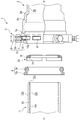
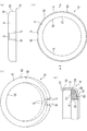
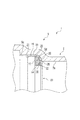
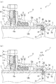
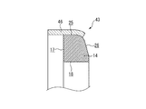
本発明の実施例を図面に基づいて説明すると、先ず図1は、本発明の実施例における管継手の配設状況を示す概略図である。図2は、受口部と挿口部とを示す断面図である。図3(a)は、防食手段を示す正面図であり、(b)は、防食手段を示す右側面図であり、(c)は防食手段を示す左側面図であり、(d)は、図3(b)のA−A断面図である。図4は、防食手段が受口部に挿入されている状態を示す断面図である。図5は、防食手段が配置位置に配置された状態を示す拡大断面図である。図6(a)は、挿口部が挿入方向に挿入された状態を示す断面図であり、(b)は、挿口部が図6(a)の状態からさらに挿入方向に挿入された後、挿口部の抜脱が規制された状態を示す断面図である。   DESCRIPTION OF THE PREFERRED EMBODIMENTS An embodiment of the present invention will be described with reference to the drawings. First, FIG. 1 is a schematic view showing an arrangement state of pipe joints in the embodiment of the present invention. FIG. 2 is a cross-sectional view showing the receiving portion and the insertion portion. 3 (a) is a front view showing the anticorrosion means, (b) is a right side view showing the anticorrosion means, (c) is a left side view showing the anticorrosion means, and (d) is It is AA sectional drawing of FIG.3 (b). FIG. 4 is a cross-sectional view showing a state in which the anticorrosion means is inserted into the receiving portion. FIG. 5 is an enlarged cross-sectional view showing a state in which the anticorrosion means is arranged at the arrangement position. FIG. 6A is a cross-sectional view showing a state where the insertion portion is inserted in the insertion direction, and FIG. 6B is a view after the insertion portion is further inserted in the insertion direction from the state of FIG. FIG. 5 is a cross-sectional view showing a state in which the insertion / extraction of the insertion portion is restricted.

先ず、本発明の配管路4は、本実施例の図1にて示されるように、例えば地中に配設される直管11、或いはT字管若しくは管軸に沿って一部に曲部を有するエルボ管2または曲部を有するとともに、比較的短寸であるベンド管13等の金属製の流体管から構成されており、配管内部に形成される経路を、例えば上下水道やガスなどの流体が流下したり、或いは電線等が配線されたりするようになっている。   First, as shown in FIG. 1 of the present embodiment, the pipe line 4 of the present invention is, for example, a straight pipe 11 disposed in the ground, or a curved portion partially along a T-shaped pipe or a pipe axis. The elbow pipe 2 having a curved portion or a metal fluid pipe such as a bend pipe 13 having a relatively short length, and a path formed inside the pipe, for example, water and sewage or gas A fluid flows down or an electric wire or the like is wired.

特に、地中には既設管若しくは既設ケーブルなどの既設の埋設物3が埋設されていることが多く、該埋設物3を回避して配管路4を配設することが不可避であり、エルボ管2、直管11、ベンド管13を適宜組み合わせて、該管同士を管継手1、100を介して接続することにより所望の配管経路を構成できる。このように配管路4を構成する部材の種類は多岐にわたり、各々の部材を接続する管継手については、配管内部を流下する流体が外部に漏洩することなく密封することが必要とされる。   In particular, existing buried objects 3 such as existing pipes or existing cables are often buried in the ground, and it is inevitable to arrange the piping 4 while avoiding the buried objects 3. 2, a straight pipe 11 and a bend pipe 13 are appropriately combined, and the pipes can be connected to each other via the pipe joints 1 and 100 to form a desired pipe path. As described above, the types of members constituting the pipe line 4 are various, and the pipe joints connecting the respective members are required to be sealed without leaking the fluid flowing down inside the pipe.

また、エルボ管2、直管11及びベンド管13の夫々の両端には、一方の管体を他方の管体に挿入して接続するために一端に形成された大径をなす受口部5と、他端に形成された挿口部12と、を有しており、これら挿口部12及び受口部5は管継手1,100の一部を構成している。また、これら各流体管の表面(内周面、外周面、管端面)には防食塗料等が塗布され、防食用のコーティング層が形成されている。   Further, at both ends of the elbow pipe 2, the straight pipe 11 and the bend pipe 13, a receiving portion 5 having a large diameter formed at one end in order to insert and connect one pipe body to the other pipe body. And the insertion portion 12 formed at the other end, and the insertion portion 12 and the receiving portion 5 constitute a part of the pipe joints 1 and 100. Moreover, anticorrosion paint etc. are apply | coated to the surface (an inner peripheral surface, an outer peripheral surface, a pipe end surface) of these each fluid pipe | tube, and the coating layer for anticorrosion is formed.

尚、管継手1及び各管継手100は略同様に構成されているため、以下においては、エルボ管2の受口部5と直管11の挿口部12とからなる管継手1を管継手の一例として説明し、他の管継手100に関する説明は省略することとする。   In addition, since the pipe joint 1 and each pipe joint 100 are comprised in substantially the same way, below, the pipe joint 1 which consists of the receiving part 5 of the elbow pipe 2 and the insertion part 12 of the straight pipe 11 is used as a pipe joint. It will be described as an example, and description regarding the other pipe joint 100 will be omitted.

図2に示されるように、本実施例における管継手1は、受口部5を備えたエルボ管2と、受口部5の内周面に挿入される挿口部12を備えた直管11と、弾性を有し受口部5の内周面と受口部5に挿入される挿口部12の外周面12aとの間から流体が漏出することを防止するシール部材8と、挿口部12の管端面12cの腐食を防止する防食手段23と、受口部5から挿口部12の抜脱を規制する抜脱規制手段15と、から構成されている。   As shown in FIG. 2, the pipe joint 1 in this embodiment includes an elbow pipe 2 having a receiving portion 5 and a straight pipe having an insertion portion 12 inserted into the inner peripheral surface of the receiving portion 5. 11, a sealing member 8 that has elasticity and prevents leakage of fluid from between the inner peripheral surface of the receiving port 5 and the outer peripheral surface 12a of the insertion port 12 inserted into the receiving port 5. The anti-corrosion means 23 for preventing the corrosion of the pipe end surface 12 c of the mouth portion 12 and the removal restricting means 15 for restricting the removal of the insertion portion 12 from the receiving portion 5 are configured.

管継手1の接続については後述するが、この挿口部12が受口部5に図2紙面右側に向かう挿入方向に挿入され、抜脱規制手段15で受口部5から挿口部12の抜脱を規制する。以下、図2紙面左側から右側に向かう方向を挿入方向として説明する。   Although the connection of the pipe joint 1 will be described later, the insertion portion 12 is inserted into the receiving portion 5 in the insertion direction toward the right side in FIG. 2, and the removal restricting means 15 connects the receiving portion 5 to the insertion portion 12. Regulate withdrawal. Hereinafter, the direction from the left side to the right side of FIG. 2 will be described as the insertion direction.

図2に示されるように、挿口部12の内径(コーティング層12dの内径)は、エルボ管2の管奥側の内周面5gの内径と略同径であり、挿口部12の外径は、受口部5の内径よりもわずかに小径であって、直管11の外周面12aの先端近傍には、面取り加工が施されている。また、挿口部12の先端には、挿口部12の外周面12aと挿口部12の内周面12bと、に連続する周方向に沿って形成された管端面12cを有している。尚、この管端面12cは後述する現場における切断により金属素地が露呈した面となっている。   As shown in FIG. 2, the inner diameter of the insertion portion 12 (the inner diameter of the coating layer 12 d) is substantially the same as the inner diameter of the inner peripheral surface 5 g of the elbow pipe 2 on the inner side of the elbow pipe 2. The diameter is slightly smaller than the inner diameter of the receiving port 5, and chamfering is performed near the tip of the outer peripheral surface 12 a of the straight pipe 11. Further, at the distal end of the insertion portion 12, there is a tube end surface 12 c formed along the circumferential direction continuous to the outer peripheral surface 12 a of the insertion portion 12 and the inner peripheral surface 12 b of the insertion portion 12. . In addition, this pipe end surface 12c is a surface where the metal substrate is exposed by cutting at a site to be described later.

シール部材8と防食手段23が装着されるエルボ管2の受口部5の内部には、エルボ管2の開口端側に周方向に沿って設けられた凹部5aが形成されている。尚、特に図示しないが、受口部5の内部を形成する内周面にも、挿口部12と同様にコーティング層が薄層に設けられている。   A recess 5 a is formed in the opening portion 5 of the elbow pipe 2 to which the seal member 8 and the anticorrosion means 23 are attached, and is provided along the circumferential direction on the opening end side of the elbow pipe 2. Although not particularly shown, a coating layer is provided in a thin layer on the inner peripheral surface forming the interior of the receiving portion 5 as well as the insertion portion 12.

凹部5aよりも管奥側の内周面には、管軸Cと略平行をなす収容面5cが形成されており、この収容面5cの管奥側の端部から、収容面5cよりも小径の内周面5gに連設するように、管軸Cに略直角に近い奥端面5dが形成されている。すなわち、収容面5cと奥端面5dとで段差が形成されている。   A housing surface 5c that is substantially parallel to the tube axis C is formed on the inner peripheral surface on the tube inner side than the recess 5a. From the end of the housing surface 5c on the tube inner side, the diameter is smaller than that of the housing surface 5c. A rear end surface 5d that is substantially perpendicular to the tube axis C is formed so as to be connected to the inner peripheral surface 5g. That is, a step is formed between the accommodation surface 5c and the back end surface 5d.

シール部材8は、図2に示されるように、受口部5の内周面に周方向に沿って形成される凹部5aに嵌合される嵌合部8aと、受口部5の内周面と受口部5に挿入される挿口部12の外周面12aとの間隙を水密的に密封するバルブ部8cと、を有しており、外径が受口部5の内径と略同径のリング体からなり、弾性を有するゴム体からなる(図6(a)参照)。   As shown in FIG. 2, the seal member 8 includes a fitting portion 8 a that is fitted in a recess 5 a that is formed along the circumferential direction on the inner peripheral surface of the receiving portion 5, and the inner periphery of the receiving portion 5. And a valve portion 8c for watertightly sealing a gap between the surface and the outer peripheral surface 12a of the insertion portion 12 to be inserted into the receiving portion 5, and the outer diameter is substantially the same as the inner diameter of the receiving portion 5. It consists of a ring body having a diameter and a rubber body having elasticity (see FIG. 6 (a)).

シール部材8は、受口部5の内周面に形成される凹部5aに嵌合部8aが周方向に亘って嵌合されている(図6(a)参照)また、バルブ部8cは、該嵌合された状態において、図2に示されるように、直管11の挿口部12が未だ挿入されずに、バルブ部8cの圧縮がされない状態において、断面形状が略円形に形成されているとともに、嵌合部8aと比較して、内周面が管軸Cに向かって膨出している。   The seal member 8 has a fitting portion 8a fitted in a concave portion 5a formed on the inner peripheral surface of the receiving portion 5 in the circumferential direction (see FIG. 6A). In the fitted state, as shown in FIG. 2, the insertion portion 12 of the straight pipe 11 has not been inserted yet, and the valve portion 8c is not compressed. In addition, the inner peripheral surface bulges toward the tube axis C as compared with the fitting portion 8a.

抜脱規制手段15は、受口部5の外端近傍の外周面に周方向に所定間隔おきに複数形成されたボルト孔5bと、エルボ管2の外方から管軸Cに対し直交する方向に向かってボルト孔5bに螺挿された押し込みボルト9と、押し込みボルト9の先方であって、受口部5の外端近傍の内周面に周方向に所定間隔おきに複数(本実施例では60度間隔おきに6個)形成された円弧溝7と、該円弧溝7内に配置され、先端に尖鋭刃10aを有している複数の固定つめ10と、から構成されており、この抜脱規制手段15により、受口部5と挿口部12とが接続され、受口部5からの挿口部12の抜脱を規制できるようになっている。   The extraction restriction means 15 includes a plurality of bolt holes 5b formed at predetermined intervals in the circumferential direction on the outer peripheral surface in the vicinity of the outer end of the receiving portion 5, and a direction orthogonal to the tube axis C from the outside of the elbow pipe 2. And a plurality of push bolts 9 screwed into the bolt holes 5b, and a plurality of the bolts at predetermined intervals in the circumferential direction on the inner peripheral surface in the vicinity of the outer end of the receiving portion 5 (the present embodiment). 6 at intervals of 60 degrees), and a plurality of fixed claws 10 disposed in the arc groove 7 and having a sharp edge 10a at the tip. The outlet portion 5 and the insertion portion 12 are connected to each other by the removal restriction means 15 so that the removal of the insertion portion 12 from the reception portion 5 can be restricted.

また、図2に示されるように、挿口部12が挿入されない状態においては、後述する挿口部12の挿入の邪魔にならないように、固定つめ10の尖鋭刃10aが、受口部5の内周面よりも外方に退避している。尚、押し込みボルト9は、必ずしも管軸に対し直交する方向に螺挿されるに限られず、管軸に対し平行若しくは斜方向に螺挿されるものであってもよい。   In addition, as shown in FIG. 2, in a state where the insertion portion 12 is not inserted, the sharp blade 10 a of the fixed claw 10 is attached to the receiving portion 5 so as not to interfere with the insertion of the insertion portion 12 described later. Retreats outward from the inner peripheral surface. The push-in bolt 9 is not necessarily screwed in a direction orthogonal to the tube axis, and may be screwed in a direction parallel or oblique to the tube axis.

防食手段23は、図2、図3(a)〜(d)に示されるように、環状に形成され、弾性を有するゴム体からなる防食部材14と、防食部材14の周方向に沿って環状に設けられ、防食部材14よりも弾性変形しにくい金属から成る保持部16と、から形成されており、本実施例においてはこの防食部材14の外径は、自然状態において保持部16の内径よりも僅かに大とされており、防食部材14が若干径方向に収縮して保持部16により嵌合され、この嵌合状態が維持されている。   As shown in FIG. 2 and FIGS. 3A to 3D, the anticorrosion means 23 is formed in an annular shape, and is formed in an annular shape along the circumferential direction of the anticorrosion member 14 formed of an elastic rubber body. And the holding portion 16 made of a metal that is less elastically deformed than the anticorrosion member 14. In this embodiment, the outer diameter of the anticorrosion member 14 is naturally larger than the inner diameter of the holding portion 16. The anticorrosion member 14 is slightly contracted in the radial direction and is fitted by the holding portion 16, and this fitting state is maintained.

この防食部材14における挿口部12の管端面12cが当接する当接部には、後述する挿口部12の管端面12cと当接して管端面12cを被覆する当接面17が形成されており、この当接面17は、管端面12cと略平行をなす平坦状に形成されている(図6(a)参照)。   An abutting surface 17 that abuts on the tube end surface 12c of the insertion portion 12 to be described later and covers the tube end surface 12c is formed on the abutting portion of the anticorrosion member 14 where the tube end surface 12c of the insertion portion 12 abuts. The contact surface 17 is formed in a flat shape substantially parallel to the tube end surface 12c (see FIG. 6A).

また防食部材14には、管軸Cと略平行をなす外周面25が形成されており、この外周面25の管奥側の端部から連設する背面26が奥端面5dに略平行となるように形成されている(図5参照)。   The anticorrosion member 14 has an outer peripheral surface 25 that is substantially parallel to the tube axis C, and a back surface 26 that is continuous from the end of the outer peripheral surface 25 on the back side of the tube is substantially parallel to the inner end surface 5d. (See FIG. 5).

また、保持部16について詳しく説明すると、図2、図3(d)に示されるように、断面視略L字状に形成されており、保持部16の内周には、防食部材14の外周面25に沿って形成された内周面21が形成されている。またこの内周面21の管奥側の端部から連設する奥面22が防食部材14の背面26に沿って形成されており、防食部材14の外周面25,背面26と保持部16の内周面21,奥面22とがそれぞれ当接し、防食部材14が保持部16により嵌合されている。この嵌合状態により、防食部材14の軸心と保持部16の軸心とが一致している。   Further, the holding portion 16 will be described in detail. As shown in FIGS. 2 and 3D, the holding portion 16 is formed in a substantially L shape in sectional view, and the outer periphery of the anticorrosion member 14 is formed on the inner periphery of the holding portion 16. An inner peripheral surface 21 formed along the surface 25 is formed. Further, a back surface 22 that is continuous from the end of the inner peripheral surface 21 on the tube back side is formed along the back surface 26 of the anticorrosion member 14, and the outer peripheral surface 25, the back surface 26 of the anticorrosion member 14, and the holding portion 16. The inner peripheral surface 21 and the inner surface 22 are in contact with each other, and the anticorrosion member 14 is fitted by the holding portion 16. Due to this fitting state, the axis of the anticorrosion member 14 and the axis of the holding portion 16 coincide.

尚、保持部16には奥面22が形成されているため、防食手段23が受口部5内に挿入されても、防食部材14と保持部16とが管軸方向に対して相対移動することなく、常に奥面22と背面26との当接状態が維持される。   In addition, since the inner surface 22 is formed in the holding part 16, even if the anticorrosion means 23 is inserted into the receiving part 5, the anticorrosion member 14 and the holding part 16 move relative to the tube axis direction. The contact state between the back surface 22 and the back surface 26 is always maintained.

また保持部16は、図2、図3(a)〜(c)に示されるように、線状部材から成り、管軸方向視形状が略C字状に形成されており、この形状により、保持部16の両端部27、28が互いに接近し、保持部16が径方向に収縮することができるようになっている(図3(c)一点鎖線参照)。   Moreover, the holding | maintenance part 16 consists of a linear member as FIG.2, FIG.3 (a)-(c) shows, and the pipe-axis direction view shape is formed in the substantially C shape, Both end portions 27 and 28 of the holding portion 16 approach each other so that the holding portion 16 can contract in the radial direction (see FIG. 3 (c) one-dot chain line).

さらに、保持部16には、防食手段23が受口部5に設置された状態において、奥端面5dとの対向面に背面19が形成されており、この背面19は、図2、図3(a)〜(d)に示すように、奥端面5dと略平行に形成されている。後述するように、この背面19と奥端面5dとが当接する配置位置に防食部材14が配置された状態において、防食部材14により管端面12cを被覆することができる所定の形状に防食部材14が保持部16により保持される(図5参照)。   Furthermore, in the state where the anticorrosion means 23 is installed in the receiving portion 5, the holding portion 16 has a back surface 19 formed on the surface facing the back end surface 5 d, and this back surface 19 is shown in FIGS. As shown in a) to (d), it is formed substantially parallel to the back end face 5d. As will be described later, in the state where the anticorrosion member 14 is arranged at the arrangement position where the back surface 19 and the back end surface 5d abut, the anticorrosion member 14 has a predetermined shape capable of covering the pipe end surface 12c with the anticorrosion member 14. It is held by the holding unit 16 (see FIG. 5).

また、保持部16の内周面は、防食部材14の内周面18と略面一になるように形成されている。   Further, the inner peripheral surface of the holding portion 16 is formed so as to be substantially flush with the inner peripheral surface 18 of the anticorrosion member 14.

保持部16の自然状態の外径は、受口部5の収容面5cにおける内径よりも、若干長寸に形成されており、図4に示されるように、防食手段23が受口部5の収容面5c内に挿入された状態において、保持部16が径方向に伸縮し、保持部16の外周面20が受口部5の収容面5cと当接している。   The outer diameter of the holding portion 16 in the natural state is slightly longer than the inner diameter of the receiving surface 5c of the receiving portion 5, and the anticorrosion means 23 is provided on the receiving portion 5 as shown in FIG. In a state of being inserted into the receiving surface 5 c, the holding portion 16 expands and contracts in the radial direction, and the outer peripheral surface 20 of the holding portion 16 is in contact with the receiving surface 5 c of the receiving portion 5.

また、本実施例においては、防食手段23が受口部5内に挿入される際において、受口部5内に防食手段23を挿入しやすくするために、保持部16は防食部材14より滑り抵抗が小さい金属から成る。   Further, in the present embodiment, when the anticorrosion means 23 is inserted into the receiving portion 5, the holding portion 16 slides more than the anticorrosion member 14 in order to facilitate the insertion of the anticorrosion means 23 into the receiving portion 5. Made of metal with low resistance.

次に、本発明の管継手1の接続について説明する。   Next, the connection of the pipe joint 1 of the present invention will be described.

先ず、図4に示されるように、エルボ管2の管端開口から受口部5内に防食手段23を軸方向に挿入する(図中一点鎖線の防食手段23参照)。さらに防食手段23を受口部5の管奥側に挿入していくと、防食手段23の管奥側の先端が収容面5cの受口部5の開口側端部に到達する。しかし、この状態においては、保持部16の外径は受口部5の収容面5cにおける内径よりも、若干長寸に形成されているため、両端部27、28が互いに接近することにより保持部16を径方向に収縮し、更に管奥側に防食手段23を挿入する。これにより、保持部16の外周面20が両端部27、28に形成される間隙を除いて収容面5cと周方向に亘って当接した状態で防食手段23を更に管奥側に挿入することできる。   First, as shown in FIG. 4, the anticorrosion means 23 is inserted into the receiving portion 5 from the tube end opening of the elbow pipe 2 in the axial direction (see the anticorrosion means 23 indicated by a one-dot chain line in the figure). When the anticorrosion means 23 is further inserted into the tube back side of the receiving portion 5, the tip of the anticorrosion means 23 on the tube back side reaches the opening side end portion of the receiving portion 5 of the receiving surface 5c. However, in this state, since the outer diameter of the holding part 16 is slightly longer than the inner diameter of the receiving surface 5c of the receiving part 5, the holding part 16 and the both end parts 27 and 28 approach each other. 16 is contracted in the radial direction, and the anticorrosion means 23 is further inserted on the back side of the tube. Accordingly, the anticorrosion means 23 is further inserted into the back of the pipe in a state where the outer peripheral surface 20 of the holding portion 16 is in contact with the accommodation surface 5c in the circumferential direction except for the gap formed at both end portions 27 and 28. it can.

防食部材14は、保持部16よりも弾性変形し易い形状になっているため、防食部材14も自然状態から保持部16に追従して弾性変形し、所定の形状、すなわち、防食部材14により管端面12cを周方向に亘って被覆することができる形状に防食部材14が形成される。ここで前記所定の形状は、保持部16に追従して、受口部5の内周面に向かう径方向の弾性復帰力により形成される。尚、防食部材14の外周面25,背面26は、保持部16の内周面21,奥面22がそれぞれ周方向に亘って当接した状態を維持している。   Since the anticorrosion member 14 has a shape that is more easily elastically deformed than the holding portion 16, the anticorrosion member 14 also elastically deforms following the holding portion 16 from the natural state, and the tube is formed by a predetermined shape, that is, the anticorrosion member 14. The anticorrosion member 14 is formed in a shape capable of covering the end surface 12c in the circumferential direction. Here, the predetermined shape is formed by an elastic restoring force in the radial direction following the holding portion 16 and moving toward the inner peripheral surface of the receiving portion 5. In addition, the outer peripheral surface 25 and the back surface 26 of the anticorrosion member 14 are maintaining the state which the inner peripheral surface 21 and the back surface 22 of the holding | maintenance part 16 contact | abutted over the circumferential direction, respectively.

また、この状態においては、線状部材からなる保持部16の管軸方向視形状が略C字状に形成されているため、保持部16の両端部27、28が互いに接近して径方向に保持部16を収縮させることができ、この収縮状態で防食部材14を受口部5内に挿入されるため、保持部16の受口部5の内周面に向かう径方向の弾性復帰力により防食部材14が周方向に沿って均一に押圧される。これにより防食部材14と受口部5との軸心を確実に合わせて防食部材14を受口部5内に挿入することができる。   Further, in this state, the tube axis direction view shape of the holding portion 16 made of a linear member is formed in a substantially C shape, so that both end portions 27 and 28 of the holding portion 16 approach each other in the radial direction. Since the holding part 16 can be contracted and the anticorrosion member 14 is inserted into the receiving part 5 in this contracted state, the elastic restoring force in the radial direction toward the inner peripheral surface of the receiving part 5 of the holding part 16 The anticorrosion member 14 is pressed uniformly along the circumferential direction. Accordingly, the anticorrosion member 14 can be inserted into the receiving portion 5 with the axial centers of the anticorrosion member 14 and the receiving portion 5 being reliably aligned.

次いで、この収縮状態で防食手段23を管奥側にさらに挿入する(図4実線の防食手段23)。この状態においては、防食部材14の該所定の形状から弾性変形されることはなく、保持部16と防食部材14との当接に生じる弾性変形が制限された状態で防食手段23が管奥側に挿入される。つまり、保持部16により防食部材14が前記所定の形状を保持して管奥側に挿入される。   Next, in this contracted state, the anticorrosion means 23 is further inserted into the back side of the pipe (the anticorrosion means 23 in FIG. 4). In this state, the anticorrosion member 14 is not elastically deformed from the predetermined shape, and the anticorrosion means 23 is located on the back side of the tube in a state where the elastic deformation caused by the contact between the holding portion 16 and the anticorrosion member 14 is limited. Inserted into. That is, the anticorrosion member 14 is inserted into the inner side of the pipe while holding the predetermined shape by the holding portion 16.

保持部16には、防食部材14の外周面25に沿ってこの外周面25をカバーするように、外周面20、内周面21が形成されているため、防食部材14が受口部5の内周面に当接することなく挿入される。よって防食部材14を受口部5内に挿入しやすい。   Since the outer peripheral surface 20 and the inner peripheral surface 21 are formed on the holding portion 16 so as to cover the outer peripheral surface 25 along the outer peripheral surface 25 of the anticorrosive member 14, the anticorrosive member 14 is connected to the receiving portion 5. Inserted without contacting the inner peripheral surface. Therefore, it is easy to insert the anticorrosion member 14 into the receiving portion 5.

さらに、保持部16が滑り抵抗が小さい材質で形成されているため、保持部16における収容面5cとの摩擦抵抗が小さいため、防食部材14が受口部5内に挿入しやすい。   Furthermore, since the holding part 16 is formed of a material having a low sliding resistance, the frictional resistance of the holding part 16 with the accommodating surface 5c is low, and thus the anticorrosion member 14 is easily inserted into the receiving part 5.

そして、図4の状態からさらに防食手段23が管奥側に挿入されると、図5に示されるように、背面19が奥端面5dと当接する配置位置に配置される。これにより、背面19が奥端面5dと当接することにより位置決めすることができるため、防食部材14が捩れることなく防食部材14を受口部5内の配置位置に配置することができる。   Then, when the anticorrosion means 23 is further inserted into the tube back side from the state of FIG. 4, as shown in FIG. 5, the back surface 19 is disposed at the disposition position where it abuts the back end surface 5d. Thereby, since the back surface 19 can be positioned by contacting the back end surface 5d, the anticorrosion member 14 can be disposed at the arrangement position in the receiving portion 5 without the anticorrosion member 14 being twisted.

また、図5の状態において、保持部16と防食部材14とが径方向に収縮しており、保持部16が受口部の収容面5cを押圧することにより保持部16の外周面20が両端部27、28に形成される間隙を除いて周方向に亘って収容面5cと当接しているため、受口部5の軸心と保持部16の軸心が一致しており、防食部材14の径方向に向かう弾性復帰力が保持部16の内周面21を押圧する。よって防食部材14と受口部5との軸心が一致し、防食部材14が位置ずれすることはなく、防食部材14が前記所定の形状を保持して配置位置に配置されることになる。   Further, in the state of FIG. 5, the holding portion 16 and the anticorrosion member 14 are contracted in the radial direction, and the holding portion 16 presses the receiving surface 5c of the receiving portion, so that the outer peripheral surface 20 of the holding portion 16 is at both ends. Since it is in contact with the receiving surface 5c in the circumferential direction except for the gap formed in the portions 27 and 28, the shaft center of the receiving portion 5 and the shaft center of the holding portion 16 coincide with each other, and the anticorrosion member 14 The elastic restoring force toward the radial direction presses the inner peripheral surface 21 of the holding portion 16. Therefore, the axes of the anticorrosion member 14 and the receiving portion 5 coincide with each other, and the anticorrosion member 14 is not displaced, and the anticorrosion member 14 is arranged at the arrangement position while maintaining the predetermined shape.

そして、防食部材14を設置した後、エルボ管2の受口部5の開口端から受口部5内にシール部材8を挿入し、受口部5の凹部5aに嵌合部8aを嵌合させて装着する(図5(a)参照)。尚、受口部5内への防食部材14の装着作業若しくはシール部材8の装着作業は、エルボ管2の出荷段階において予め完了させる場合もあるし、管継手1の接続現場において実施する場合もある。   Then, after the anticorrosion member 14 is installed, the seal member 8 is inserted into the receiving portion 5 from the opening end of the receiving portion 5 of the elbow pipe 2, and the fitting portion 8 a is fitted into the concave portion 5 a of the receiving portion 5. (See FIG. 5A). In addition, the mounting operation of the anticorrosion member 14 or the mounting operation of the seal member 8 in the receiving portion 5 may be completed in advance at the shipping stage of the elbow pipe 2 or may be performed at the connection site of the pipe joint 1. is there.

次いで、エルボ管2の管端開口内に直管11の挿口部12が挿入されると、挿口部12の外周面12aが受口部5の内周面に嵌合されたシール部材8の嵌合部8aと摺接しつつ、受口部5に挿入され、バルブ部8cを挿口部12の外周面12aと受口部5の内周面との間隙内で圧縮する。これにより、受口部5の内周面と挿口部12の外周面12aとの間隙が密封され、受口部5の内周面と挿口部12の外周面12aとの間からの流体の漏出が防止される。   Next, when the insertion portion 12 of the straight tube 11 is inserted into the tube end opening of the elbow tube 2, the sealing member 8 in which the outer peripheral surface 12 a of the insertion portion 12 is fitted to the inner peripheral surface of the receiving portion 5. While being in sliding contact with the fitting portion 8 a, the valve portion 8 c is inserted into the receiving portion 5, and the valve portion 8 c is compressed in the gap between the outer peripheral surface 12 a of the inserting portion 12 and the inner peripheral surface of the receiving portion 5. Thereby, the gap between the inner peripheral surface of the receiving portion 5 and the outer peripheral surface 12a of the insertion portion 12 is sealed, and the fluid from between the inner peripheral surface of the receiving portion 5 and the outer peripheral surface 12a of the insertion portion 12 is sealed. Leakage is prevented.

次いで、防食部材14を受口部5内に設置した後、シール部材8を挿入して配置し、挿口部12を受口部5内に挿入していく。   Next, after the anticorrosion member 14 is installed in the receiving portion 5, the sealing member 8 is inserted and arranged, and the insertion portion 12 is inserted into the receiving portion 5.

そして、図6(a)に示されるように、挿口部12の先端が当接面17と当接する被覆開始位置aまで挿入される。   Then, as shown in FIG. 6A, the insertion end 12 is inserted to the covering start position a where the tip of the insertion portion 12 comes into contact with the contact surface 17.

ここで、当接面17は平坦状に形成されているため、管端面12cが当接面17に当接した段階で管端面12cが略全域にわたり当接面17により被覆される。   Here, since the contact surface 17 is formed in a flat shape, the tube end surface 12c is covered with the contact surface 17 over substantially the entire region when the tube end surface 12c contacts the contact surface 17.

次いで、被覆開始位置aから更に挿口部12が管奥側に挿入されると、防食部材14は、管端面12cと受口部5の奥端面5dとの間で管軸方向に挟圧された状態となり、管端面12cにより当接面17が押圧されて防食部材14の弾性変形が開始され、これにより主に防食部材14の内周面18側が管軸に向けて押し出される。このように防食部材14が押し潰されて弾性変形が開始された状態において、管端面12cに対して防食部材14の弾性復帰力が作用することになるため、管端面12cが当接面17により被覆される被覆状態となる。   Next, when the insertion portion 12 is further inserted into the tube back side from the coating start position a, the anticorrosion member 14 is pinched in the tube axis direction between the tube end surface 12c and the back end surface 5d of the receiving portion 5. The contact surface 17 is pressed by the pipe end surface 12c, and the anticorrosion member 14 starts to be elastically deformed. As a result, the inner peripheral surface 18 side of the anticorrosion member 14 is mainly pushed toward the tube axis. In this state where the anticorrosion member 14 is crushed and elastic deformation is started, the elastic return force of the anticorrosion member 14 acts on the tube end surface 12 c, so that the tube end surface 12 c is brought into contact with the contact surface 17. It becomes the covering state to be coated.

そして、本実施例においては、図6(b)に示されるように、挿口部12は、管端面12cが前記被覆開始位置aから更に被覆幅寸法L分僅かに管奥側の挿入完了位置bまで受口部5に挿入された時点で挿入作業が終了される。つまり、被覆開始位置aからL分挿入方向に挿口部12を挿入し、防食部材14を押し潰すことにより、当接面17による管端面12cの水密性が維持される。さらに、防食部材14の内周面18側が管軸方向に押し出されて膨出することで、挿口部12の内周面12bにおける当接面17の近傍位置が、膨出した防食部材14の内周面18側により若干被覆され、水密状態になる。   In the present embodiment, as shown in FIG. 6 (b), the insertion opening 12 has an insertion completion position where the tube end surface 12c is slightly further from the coating start position a by the coating width dimension L. The insertion operation is completed when the insertion part 5 is inserted up to b. That is, by inserting the insertion portion 12 in the insertion direction L from the coating start position a and crushing the anticorrosion member 14, the water tightness of the tube end surface 12c by the contact surface 17 is maintained. Furthermore, when the inner peripheral surface 18 side of the anticorrosion member 14 is pushed out in the tube axis direction and bulges, the position near the contact surface 17 on the inner peripheral surface 12b of the insertion portion 12 is increased. It is covered slightly by the inner peripheral surface 18 side and becomes watertight.

そして管端面12cが前記挿入完了位置cに到達した状態において、この状態を保持したまま、押し込みボルト9を円弧溝7の外側からねじ込み、固定つめ10を挿口部12の外周面12aに押し付け、押し込みボルト9をさらに螺入し、固定つめ10の尖鋭刃10aを管軸に向けて押圧して挿口部12の外周面12aに食い込ませ、受口部5と挿口部12とを接続する。これにより、受口部5からの挿口部12の抜脱が規制された規制状態となる。   Then, in the state where the tube end surface 12c has reached the insertion completion position c, the push bolt 9 is screwed from the outside of the arc groove 7 while maintaining this state, and the fixing claw 10 is pressed against the outer peripheral surface 12a of the insertion portion 12. The push-in bolt 9 is further screwed in, and the sharp blade 10a of the fixed claw 10 is pressed toward the tube axis to bite into the outer peripheral surface 12a of the insertion portion 12, and the receiving portion 5 and the insertion portion 12 are connected. . Thereby, it will be in the control state in which removal of the insertion part 12 from the receiving part 5 was controlled.

つまり、受口部5に対する挿口部12の図6(b)の紙面右側から左側に向かう抜脱方向への移動を規制した状態で保持する固定つめ10の保持力は、防食部材14の弾性復帰力よりも大とされている。   That is, the holding force of the fixed pawl 10 that holds the insertion portion 12 with respect to the receiving portion 5 in a state where the movement from the right side to the left side in FIG. It is considered to be greater than the return force.

従って、管端面12cが、前記被覆開始位置aから前記挿入完了位置b間に位置している状態においては、当接面17により管端面12cが略全域にわたり密着されている被覆状態であるため、抜脱規制手段15により受口部5からの挿口部12の抜脱が規制されることで、防食部材14により管端面12cが被覆される被覆状態が維持される。   Accordingly, in the state where the tube end surface 12c is located between the covering start position a and the insertion completion position b, the tube end surface 12c is in a covering state in which the tube end surface 12c is in close contact with the entire region. By restricting the removal of the insertion portion 12 from the receiving portion 5 by the removal restriction means 15, the covering state in which the pipe end surface 12 c is covered by the anticorrosion member 14 is maintained.

以上に説明したように、本実施例の管継手1においては、防食部材14には、防食部材14よりも弾性変形しにくい材質から成る保持部16が防食部材14の周方向に沿って設けられ、防食部材14は、保持部16により所定の形状を保持して保持部の背面19と奥端面5dとが当接する配置位置に配置されている。このため、防食部材14を受口部5内に挿入して該配置位置に配置する際、防食部材14よりも弾性変形しにくい保持部16により、受口部5の収容面5cと、保持部16との当接により生じる防食部材14の弾性変形が制限されるため、防食部材14が型崩れすることなく所定の形状を保持して、防食部材14を容易に受口部5内の前記配置位置に配置することができる。   As described above, in the pipe joint 1 of the present embodiment, the anticorrosion member 14 is provided with the holding portion 16 made of a material that is less elastically deformed than the anticorrosion member 14 along the circumferential direction of the anticorrosion member 14. The anticorrosion member 14 is disposed at an arrangement position where the holding portion 16 holds a predetermined shape and the back surface 19 of the holding portion and the back end surface 5d abut. For this reason, when the anticorrosion member 14 is inserted into the receiving portion 5 and disposed at the arrangement position, the holding surface 16 of the receiving portion 5 and the holding portion are held by the holding portion 16 that is less elastically deformed than the anticorrosion member 14. Since the elastic deformation of the anticorrosion member 14 caused by the contact with 16 is limited, the anticorrosion member 14 is maintained in a predetermined shape without losing its shape, and the anticorrosion member 14 is easily disposed in the receiving portion 5. Can be placed in position.

また、本実施例では、抜脱規制手段15により受口部5からの挿口部12の抜脱が規制され、この受口部5からの挿口部12の抜脱が規制されている状態において、防食部材14は弾性変形した状態で管端面12cを被覆しており、その弾性復帰力により管端面12cを押圧するため、防食部材14により管端面12cのシール性を常に維持することができる。   Further, in this embodiment, the removal restricting means 15 regulates the removal of the insertion portion 12 from the receiving portion 5, and in the state where the removal of the insertion portion 12 from the receiving portion 5 is restricted, The anticorrosion member 14 covers the tube end surface 12c in an elastically deformed state, and the tube end surface 12c is pressed by its elastic restoring force. Therefore, the sealability of the tube end surface 12c can always be maintained by the anticorrosion member 14.

(変形例)
次に、本発明の管継手の変形例を、図7〜図11に基づいて説明する。図7は、変形例1を示す防食手段の正面図である。図8は、変形例2を示す防食手段の断面図である。図9は、変形例3を示す防食手段の断面図である。図10は、変形例4を示す防食手段の断面図である。図11は、変形例5を示す防食手段の断面図である。
(Modification)
Next, a modification of the pipe joint of the present invention will be described with reference to FIGS. FIG. 7 is a front view of the anticorrosion means showing the first modification. FIG. 8 is a cross-sectional view of the anticorrosion means showing the second modification. FIG. 9 is a cross-sectional view of the anticorrosion means showing the third modification. FIG. 10 is a cross-sectional view of the anticorrosion means showing the fourth modification. FIG. 11 is a cross-sectional view of the anticorrosion means showing the fifth modification.

変形例に係る管継手は、保持部材の形状が異なっているだけで、他の構成は実施例で示した管継手1の形態とほぼ同様であるため、同様の構成部位には同一の符号を付すことにより、ここでの詳細な説明は省略することとする。   The pipe joint according to the modified example is different in only the shape of the holding member, and the other configuration is substantially the same as the form of the pipe joint 1 shown in the embodiment. Therefore, detailed description here will be omitted.

本実施例においては、保持部16は、管軸方向視形状が略C字状に防食部材14の周方向に沿って形成されているが、例えば変形例1として、図7に示されるように、所定間隔おきに複数(本変形例において90°おきに4個)の保持部36が防食部材14の外周面25と、この外周面25と連続した背面26と、に沿って形成された防食手段33であってもよい。このようにすることで、防食部材14が径方向に収縮した状態で防食部材14が受口部内の配置位置に配置されることにより、その径方向に向かう弾性復帰力が保持部36を押圧し、この押圧力が保持部36に作用し、該保持部36が受口部の内周面(本実施例における収容面5c)を径方向に押圧するため、防食部材14と受口部との軸心を合わせることができ、防食部材14が位置ずれすることはない。尚、変形例1では、所定間隔おきに複数の保持部36が形成されているが、これに限らず、この複数の保持部に連設されるとともに、防食部材の背面に沿って形成された連設部を有する一体の保持部であってもよい。   In the present embodiment, the holding portion 16 is formed in a substantially C shape in the tube axis direction along the circumferential direction of the anticorrosion member 14, for example, as Modification 1 as shown in FIG. 7. Further, a plurality of holding portions 36 (four at every 90 ° in this modification) at predetermined intervals are formed along the outer peripheral surface 25 of the anticorrosive member 14 and the back surface 26 continuous with the outer peripheral surface 25. The means 33 may be used. By doing in this way, when the anticorrosion member 14 is contracted in the radial direction and the anticorrosion member 14 is arranged at the arrangement position in the receiving portion, the elastic return force in the radial direction presses the holding portion 36. The pressing force acts on the holding portion 36, and the holding portion 36 presses the inner peripheral surface (the receiving surface 5c in the present embodiment) of the receiving portion in the radial direction. The axes can be aligned and the anticorrosion member 14 is not displaced. In the first modification, the plurality of holding portions 36 are formed at predetermined intervals. However, the present invention is not limited to this, and the plurality of holding portions 36 are formed continuously along the plurality of holding portions and along the back surface of the anticorrosion member. An integral holding part having a continuous part may be used.

また、本実施例、変形例1においては、防食部材14の外周面25に対向する全域に周方向に沿って保持部16、36が形成されているが、これに限らず、管軸方向に所定間隔おきの複数の保持部が防食部材の外周面に周方向に沿って形成されてもよい。   Further, in the present embodiment and the first modification, the holding portions 16 and 36 are formed along the circumferential direction in the entire region facing the outer peripheral surface 25 of the anticorrosion member 14, but not limited thereto, in the tube axis direction. A plurality of holding portions at predetermined intervals may be formed on the outer peripheral surface of the anticorrosion member along the circumferential direction.

また、本実施例においては、防食部材14の外周面25と背面26とに沿って保持部16が設けられているが、これに限らず、変形例2として、図8に示されるように防食部材14の外周面25のみ沿って保持部46が設けられた防食手段43であってもよい。このようにすることで、防食部材14が受口部の内周面に当接することなく配置位置まで挿入されるため、防食部材14を受口部内に挿入しやすい。   Further, in the present embodiment, the holding portion 16 is provided along the outer peripheral surface 25 and the back surface 26 of the anticorrosion member 14, but the present invention is not limited to this, and as a second modification, as shown in FIG. The anticorrosion means 43 provided with the holding portion 46 along only the outer peripheral surface 25 of the member 14 may be used. By doing in this way, since the anticorrosion member 14 is inserted to an arrangement position, without contact | abutting to the internal peripheral surface of a receiving part, it is easy to insert the anticorrosion member 14 in a receiving part.

また、変形例3として図9に示されるように、防食部材14の内周面18に周方向に沿って保持部56が設けられた防食手段53であってもよく、防食部材14の自然状態の外径は、受口部(本実施例における収容面5c)の内径よりも長寸であり、保持部56の自然状態の外径は防食部材14の自然状態の内径よりも若干長寸に形成されている。また保持部56は、特に図示はしないが管軸方向視略C字状に形成されており、防食部材14の内周面18に保持部56が径方向に伸縮された状態で嵌合されている。このようにすることで、防食手段53が受口部内に挿入される状態において、保持部56の径方向の弾性復帰力が防食部材14を押圧することにより、この押圧力が保持部56に作用し、該保持部56が受口部の内周面(本実施例における収容面5c)を周方向に沿って均一に押圧するため、防食部材14と受口部との軸心を確実に合わせて防食部材14を受口部内に挿入することができる。   Further, as shown in FIG. 9 as the third modification, the anticorrosion means 53 may be provided with a holding portion 56 provided on the inner peripheral surface 18 of the anticorrosion member 14 along the circumferential direction. The outer diameter of the holding portion 56 is longer than the inner diameter of the receiving portion (the receiving surface 5c in the present embodiment), and the outer diameter of the holding portion 56 is slightly longer than the inner diameter of the anticorrosion member 14 in the natural state. Is formed. Although not shown, the holding portion 56 is formed in a substantially C shape when viewed in the tube axis direction, and is fitted to the inner peripheral surface 18 of the anticorrosion member 14 in a state where the holding portion 56 is expanded and contracted in the radial direction. Yes. By doing in this way, in a state where the anticorrosion means 53 is inserted into the receiving portion, the elastic restoring force in the radial direction of the holding portion 56 presses the anticorrosion member 14, and this pressing force acts on the holding portion 56. Since the holding portion 56 uniformly presses the inner peripheral surface of the receiving portion (the receiving surface 5c in the present embodiment) along the circumferential direction, the anticorrosion member 14 and the receiving portion are securely aligned with each other. Thus, the anticorrosion member 14 can be inserted into the receiving portion.

さらに、変形例4として、図10に示されるように防食部材14の内部に周方向に沿って保持部66が設けられた防食手段63であってもよい。このようにすることで、保持部16が防食部材14の捩れを防止し、防食部材14を受口部内の配置位置に配置することができる。   Furthermore, as a fourth modification, as shown in FIG. 10, an anticorrosion means 63 in which a holding portion 66 is provided along the circumferential direction inside the anticorrosion member 14 may be used. By doing in this way, the holding | maintenance part 16 prevents twisting of the anticorrosion member 14, and can arrange | position the anticorrosion member 14 in the arrangement position in a receiving part.

また、図11に示されるように防食部材の背面26に沿って保持部76が設けられた防食手段73であってもよい。このようにすることで、保持部76が奥端面と当接することにより位置決めすることができるため、防食部材14が捩れることなく防食部材4を受口部内の配置位置に配置することができる。また、防食部材14と保持部76とが管軸方向に対して相対移動することがない。   Moreover, as shown in FIG. 11, the anticorrosion means 73 provided with the holding | maintenance part 76 along the back surface 26 of the anticorrosion member may be sufficient. By doing in this way, since it can position by the holding | maintenance part 76 contact | abutting with a back end surface, the anticorrosion member 4 can be arrange | positioned in the arrangement position in a receptacle part, without the anticorrosion member 14 twisting. Further, the anticorrosion member 14 and the holding portion 76 do not move relative to the tube axis direction.

以上、本発明の実施例を図面により説明してきたが、具体的な構成はこれら実施例に限られるものではなく、本発明の要旨を逸脱しない範囲における変更や追加があっても本発明に含まれる。   Although the embodiments of the present invention have been described with reference to the drawings, the specific configuration is not limited to these embodiments, and modifications and additions within the scope of the present invention are included in the present invention. It is.

本実施例においては、保持部16が金属から形成されているが、これに限らず、例えば、防食部材よりも弾性変形しにくく、且つ受口部の内周面に対する摩擦抵抗を小さい材質のものであるならば、合成樹脂等から成る保持部であってもよい。   In the present embodiment, the holding portion 16 is made of metal, but is not limited to this. For example, the holding portion 16 is made of a material that is less elastically deformed than the anticorrosion member and has a small frictional resistance against the inner peripheral surface of the receiving portion. If it is, the holding | maintenance part which consists of synthetic resins etc. may be sufficient.

また、本実施例においては、保持部16が管軸方向視形状が略C字状に形成されているが、これに限らず、保持部が環状に形成されてもよく、また防食部材の外周に点在して保持部が形成されてもよい。さらに、防食部材の外周面に沿って保持部が螺旋状に形成されてもよい。   Further, in the present embodiment, the holding portion 16 is formed in a substantially C shape in the tube axis direction view, but not limited to this, the holding portion may be formed in an annular shape, and the outer periphery of the anticorrosion member The holding portions may be formed in a scattered manner. Furthermore, the holding portion may be formed in a spiral shape along the outer peripheral surface of the anticorrosion member.

また、前記実施例においては、防食部材14とシール部材8とが別々に設けられ、かつ、互いに管軸方向に所定距離離間した状態で配置されていたため、挿口部12が挿入した状態において、それぞれ別個に弾性変形するとともに、それぞれ弾性変形した部分が互いに干渉し合うことがなく、影響を及ぼすことがない。つまり、弾性変形した防食部材14がシール部材8に干渉して水密性に支障をきたしたり、逆に弾性変形したシール部材8が防食部材14に干渉して、管端面12cの被覆に支障をきたすようなことがない。   In the embodiment, the anticorrosion member 14 and the seal member 8 are provided separately, and are arranged in a state of being separated from each other by a predetermined distance in the tube axis direction. Each elastically deforms separately, and the elastically deformed portions do not interfere with each other and do not affect each other. That is, the elastically deformed anticorrosion member 14 interferes with the seal member 8 and interferes with watertightness. Conversely, the elastically deformed seal member 8 interferes with the anticorrosion member 14 and obstructs the coating of the pipe end surface 12c. There is no such thing.

また、シール部材8には、挿口部12の外周面12aと受口部5の内周面との間からの流体の漏出を防ぐに適した弾性を有する弾性材を選択し、防食部材14には、管端面12cの防食に適した弾性を有する弾性材を選択することができるため、管端面12cの腐食及び挿口部12の外周面12aと受口部5の内周面との間からの流体の漏出を効率よく防止することができる。   For the seal member 8, an elastic material having elasticity suitable for preventing leakage of fluid from between the outer peripheral surface 12 a of the insertion portion 12 and the inner peripheral surface of the receiving portion 5 is selected, and the anticorrosion member 14 is selected. Since an elastic material having elasticity suitable for corrosion prevention of the tube end surface 12c can be selected, the corrosion of the tube end surface 12c and the gap between the outer peripheral surface 12a of the insertion portion 12 and the inner peripheral surface of the receiving portion 5 can be selected. It is possible to efficiently prevent fluid from leaking out.

また、シール部材8と防食部材14とを一体的に形成して、挿口部12の外周面12aと受口部5の内周面との間からの流体の漏出を防止するとともに、挿口部12の管端面12cの腐食を防止することができる防食部材としてもよく、このような場合、受口部5に対する部材の装着が1回で済むため、装着手間が容易になる。   In addition, the seal member 8 and the anticorrosion member 14 are integrally formed to prevent leakage of fluid from between the outer peripheral surface 12a of the insertion portion 12 and the inner peripheral surface of the receiving portion 5, and the insertion port An anticorrosion member that can prevent corrosion of the pipe end surface 12c of the portion 12 may be used. In such a case, since the member needs to be attached to the receiving portion 5 only once, it is easy to attach.

また、前記実施例では、径方向の中央部が両端部よりも挿口部12側に膨出する環状の膨出部が形成されていたが、例えば膨出部は必ずしも環状に形成されていなくてもよく、管端面との当接面から管端面に向けて複数の膨出部が周方向に沿って突設されていてもよい。   Moreover, in the said Example, although the cyclic | annular bulging part which the center part of radial direction bulges in the insertion part 12 side rather than both ends was formed, for example, the bulging part is not necessarily formed cyclically | annularly. Alternatively, a plurality of bulging portions may be provided protruding in the circumferential direction from the contact surface with the tube end surface toward the tube end surface.

また、前記実施例では、防食部材14として適宜弾性変形力を有するゴム材からなるゴム体が適用されていたが、押し潰された管端面12cに対して弾性復帰力により被覆して水密状態を形成しうるものであれば、材質はゴムに限定されるものではなく、種々の弾性材を適用可能である。   Moreover, in the said Example, although the rubber body which consists of a rubber material which has an elastic deformation force suitably was applied as the anti-corrosion member 14, it coat | covers with the elastic return force with respect to the crushed pipe end surface 12c, and makes a watertight state As long as it can be formed, the material is not limited to rubber, and various elastic materials can be applied.

また、前記実施例では、防食部材14全体が同一素材にて形成されていたが、例えば管端面との当接面近傍のみを、他の部位と比較して軟質なゴム材にて形成して潰れやすくしてもよいし、あるいは管端面との当接面近傍のみを、他の部位と比較して高反発性を有するゴム材にて形成して弾性復帰力を向上させるようにしてもよい。   Moreover, in the said Example, although the anticorrosion member 14 whole was formed with the same raw material, only the contact surface vicinity with a pipe | tube end surface is formed with a soft rubber material compared with another site | part, for example. It may be easy to be crushed, or only the vicinity of the contact surface with the pipe end surface may be formed of a rubber material having higher resilience than other parts to improve the elastic restoring force. .

また、前記実施例における抜脱規制手段は、ボルト孔5bと、固定爪10を押し込む押し込みボルト9と、固定爪10と、固定爪10が収容される円弧溝7と、から構成されていたが、受口部5に挿入された挿口部12の該受口部5からの抜脱を規制するものであれば、上記抜脱規制手段に限定されるものではなく、いわゆる押し輪等の受口部5とは別個に設けられたもの等、他の抜脱規制手段であってもよい。   Further, the removal restricting means in the above embodiment is constituted by the bolt hole 5b, the pushing bolt 9 for pushing the fixing claw 10, the fixing claw 10, and the arc groove 7 in which the fixing claw 10 is accommodated. As long as the insertion part 12 inserted into the receiving part 5 is restricted from being removed from the receiving part 5, the invention is not limited to the above-mentioned removal restricting means. Other extraction restriction means such as those provided separately from the mouth portion 5 may be used.

本発明の実施例における管継手の配設状況を示す概略図である。It is the schematic which shows the arrangement | positioning condition of the pipe joint in the Example of this invention. 受口部と挿口部とを示す断面図である。It is sectional drawing which shows a receptacle part and an insertion part. (a)は、防食手段を示す正面図であり、(b)は、防食手段を示す右側面図であり、(c)は防食手段を示す左側面図であり、(d)は、図3(b)のA−A断面図である。(A) is a front view showing anticorrosion means, (b) is a right side view showing anticorrosion means, (c) is a left side view showing anticorrosion means, and (d) is FIG. It is AA sectional drawing of (b). 防食手段が受口部に挿入されている状態を示す断面図である。It is sectional drawing which shows the state in which the anticorrosion means is inserted in the receiving part. 防食手段が配置位置に配置された状態を示す拡大断面図である。It is an expanded sectional view which shows the state by which the anticorrosion means was arrange | positioned in the arrangement position. (a)は、挿口部が挿入方向に挿入された状態を示す断面図であり、(b)は、挿口部が図6(a)の状態からさらに挿入方向に挿入された後、挿口部の抜脱が規制された状態を示す断面図である。(A) is sectional drawing which shows the state by which the insertion part was inserted in the insertion direction, (b) is a state after insertion after the insertion part is further inserted in the insertion direction from the state of Fig.6 (a). It is sectional drawing which shows the state by which extraction | extraction of the opening part was controlled. 変形例1を示す防食手段の正面図である。It is a front view of the anticorrosion means which shows the modification 1. 変形例2を示す防食手段の断面図である。It is sectional drawing of the anticorrosion means which shows the modification 2. 変形例3を示す防食手段の断面図である。It is sectional drawing of the anticorrosion means which shows the modification 3. 変形例4を示す防食手段の断面図である。It is sectional drawing of the anticorrosion means which shows the modification 4. 変形例5を示す防食手段の断面図である。It is sectional drawing of the anticorrosion means which shows the modification 5.

符号の説明Explanation of symbols

1 管継手
5 受口部
5c 収容面(受口部の内周面)
5d 奥端面
12 挿口部
12c 管端面
14 防食部材
16 保持部
1 Pipe Fitting 5 Receiving Portion 5c Housing Surface (Inner Peripheral Surface of Receiving Portion)
5d Back end surface 12 Insertion portion 12c Pipe end surface 14 Anticorrosion member 16 Holding portion

Claims (2)

押し込みボルトの螺入により内部に固定爪を押し込み可能となっている抜脱防止手段を備えた受口部を有する一方の流体管と、該受口部の奥端面に配置される防食手段により管端面が被覆される挿口部を有する他方の流体管と、を水密状態で接続する管継手であって、
前記防食手段は、弾性材から成る環状体であり、前記受口部に挿入された挿口部の管端面と当接して被覆する防食部材と、前記防食部材よりも弾性変形しにくい材質から成る径方向の弾性復帰力を有する管軸方向視略C字状であり、前記防食部材の外周を覆い、前記受口部の奥端面及び内周面に当接する保持部と、から成り、
前記挿口部を有する流体管は、前記受口部に対し軸線方向に挿入され、前記管端面が前記防食部材に押圧された状態で、前記抜脱防止手段における押し込みボルトの螺入で固定爪が挿口部に食い込み、前記受口部を有する一方の流体管に固定されることを特徴とする管継手。
One fluid pipe having a receiving portion provided with a removal preventing means capable of pushing a fixing claw into the inside by screwing a push-in bolt, and a pipe by anticorrosion means arranged on the back end face of the receiving portion. A pipe joint for connecting the other fluid pipe having an insertion portion whose end face is covered, in a watertight state,
The anticorrosion means is an annular body made of an elastic material, and is made of an anticorrosion member that comes into contact with and covers the tube end surface of the insertion portion inserted into the receiving portion, and a material that is less elastically deformed than the anticorrosion member. A tube portion in the tube axis direction having a radial elastic restoring force, and comprising a holding portion that covers the outer periphery of the anticorrosion member and contacts the inner end surface and the inner end surface of the receiving portion,
The fluid pipe having the insertion part is inserted in the axial direction with respect to the reception part, and the fixing claw is fixed by screwing a push-in bolt in the removal prevention means in a state where the pipe end surface is pressed by the anticorrosion member. Bite into the insertion part, and is fixed to one fluid pipe having the receiving part .
前記保持部は、前記防食部材よりも滑り抵抗が小さい材質から成ることを特徴とする請求項に記載の管継手。 The pipe joint according to claim 1 , wherein the holding portion is made of a material having a slip resistance smaller than that of the anticorrosion member.
JP2007175262A 2007-07-03 2007-07-03 Pipe fitting Expired - Fee Related JP5080151B2 (en)

Priority Applications (1)

Application Number Priority Date Filing Date Title
JP2007175262A JP5080151B2 (en) 2007-07-03 2007-07-03 Pipe fitting

Applications Claiming Priority (1)

Application Number Priority Date Filing Date Title
JP2007175262A JP5080151B2 (en) 2007-07-03 2007-07-03 Pipe fitting

Publications (3)

Publication Number Publication Date
JP2009014075A JP2009014075A (en) 2009-01-22
JP2009014075A5 JP2009014075A5 (en) 2010-07-22
JP5080151B2 true JP5080151B2 (en) 2012-11-21

Family

ID=40355218

Family Applications (1)

Application Number Title Priority Date Filing Date
JP2007175262A Expired - Fee Related JP5080151B2 (en) 2007-07-03 2007-07-03 Pipe fitting

Country Status (1)

Country Link
JP (1) JP5080151B2 (en)

Families Citing this family (5)

* Cited by examiner, † Cited by third party
Publication number Priority date Publication date Assignee Title
JP4976509B2 (en) * 2010-01-07 2012-07-18 株式会社沖データ Image forming apparatus
JP5580060B2 (en) * 2010-01-13 2014-08-27 コスモ工機株式会社 Pipe fitting
JP5631709B2 (en) * 2010-07-16 2014-11-26 コスモ工機株式会社 Pipe fitting
JP5723164B2 (en) * 2011-01-14 2015-05-27 コスモ工機株式会社 Rust prevention member
JP5973768B2 (en) * 2012-04-16 2016-08-23 コスモ工機株式会社 Anticorrosion ring

Family Cites Families (6)

* Cited by examiner, † Cited by third party
Publication number Priority date Publication date Assignee Title
JPS624989A (en) * 1985-06-28 1987-01-10 株式会社 西原衛生工業所 Corrosionproof core of pipe end for pipe joint and connecting method using said core
JPS62176595U (en) * 1986-04-30 1987-11-10
JP3710354B2 (en) * 1999-11-16 2005-10-26 株式会社栗本鐵工所 Pipe end anticorrosion core and method of manufacturing the same
JP3691424B2 (en) * 2001-10-17 2005-09-07 株式会社栗本鐵工所 Fixing structure of pipe end anticorrosion core, fixing ring used therefor, and pipe joint method
JP2005042878A (en) * 2003-07-25 2005-02-17 Daidore Kk Pipe joint structure
JP4454400B2 (en) * 2004-06-14 2010-04-21 株式会社クボタ Anti-corrosion structure of pipe end face

Also Published As

Publication number Publication date
JP2009014075A (en) 2009-01-22

Similar Documents

Publication Publication Date Title
JP6948372B2 (en) Pipe fitting
JP5019971B2 (en) Pipe fitting
JP5080151B2 (en) Pipe fitting
JP5154853B2 (en) Pipe fitting
JP5019963B2 (en) Pipe fitting
JP4845536B2 (en) Anti-corrosion structure of pipe end face
JP2008038924A (en) Pipe joint
JP2007138980A (en) Pipe joint
JP2008138694A (en) Pipe joint
JP4454400B2 (en) Anti-corrosion structure of pipe end face
JP2005061549A (en) Pipe joint structure for valve and resin pipe, and connecting method using the same
JP5580060B2 (en) Pipe fitting
JP2009156459A (en) Rust-proof means
JP2010181005A (en) Pipe joint and method for releasing connection of the pipe joint
JP5118160B2 (en) Pipe end anti-corrosion structure
JP5723160B2 (en) Rust prevention member
JP2008064169A (en) Pipe joint
JP2005248971A (en) Corrosion-preventive structure of pipe-end face
JP4667992B2 (en) Joint body
JP5914028B2 (en) Detachment prevention device
JP3129253B2 (en) Anti-corrosion structure at the end of pipe joint for earthquake resistance
JP2009097563A (en) Pipe joint
JP2011226598A (en) Pipe joint and rust prevention method thereof
JP2007205443A (en) Corrosion prevention means for pipe end part
JP2015164372A (en) Duct opening waterproof device

Legal Events

Date Code Title Description
A621 Written request for application examination

Free format text: JAPANESE INTERMEDIATE CODE: A621

Effective date: 20100603

A521 Written amendment

Free format text: JAPANESE INTERMEDIATE CODE: A523

Effective date: 20100604

A977 Report on retrieval

Free format text: JAPANESE INTERMEDIATE CODE: A971007

Effective date: 20120214

A131 Notification of reasons for refusal

Free format text: JAPANESE INTERMEDIATE CODE: A131

Effective date: 20120306

A521 Written amendment

Free format text: JAPANESE INTERMEDIATE CODE: A523

Effective date: 20120417

A131 Notification of reasons for refusal

Free format text: JAPANESE INTERMEDIATE CODE: A131

Effective date: 20120529

A521 Written amendment

Free format text: JAPANESE INTERMEDIATE CODE: A523

Effective date: 20120730

TRDD Decision of grant or rejection written
A01 Written decision to grant a patent or to grant a registration (utility model)

Free format text: JAPANESE INTERMEDIATE CODE: A01

Effective date: 20120821

A01 Written decision to grant a patent or to grant a registration (utility model)

Free format text: JAPANESE INTERMEDIATE CODE: A01

A61 First payment of annual fees (during grant procedure)

Free format text: JAPANESE INTERMEDIATE CODE: A61

Effective date: 20120830

FPAY Renewal fee payment (event date is renewal date of database)

Free format text: PAYMENT UNTIL: 20150907

Year of fee payment: 3

R150 Certificate of patent or registration of utility model

Free format text: JAPANESE INTERMEDIATE CODE: R150

LAPS Cancellation because of no payment of annual fees