JP2007237155A - Microbubble generator - Google Patents
Microbubble generator Download PDFInfo
- Publication number
- JP2007237155A JP2007237155A JP2006102428A JP2006102428A JP2007237155A JP 2007237155 A JP2007237155 A JP 2007237155A JP 2006102428 A JP2006102428 A JP 2006102428A JP 2006102428 A JP2006102428 A JP 2006102428A JP 2007237155 A JP2007237155 A JP 2007237155A
- Authority
- JP
- Japan
- Prior art keywords
- flow
- jet flow
- liquid
- cap
- jet
- Prior art date
- Legal status (The legal status is an assumption and is not a legal conclusion. Google has not performed a legal analysis and makes no representation as to the accuracy of the status listed.)
- Pending
Links
- 239000007788 liquid Substances 0.000 claims abstract description 49
- 239000000203 mixture Substances 0.000 claims abstract description 10
- 239000007789 gas Substances 0.000 claims description 44
- 238000005507 spraying Methods 0.000 claims description 7
- 235000014676 Phragmites communis Nutrition 0.000 claims description 5
- 238000010008 shearing Methods 0.000 claims description 5
- 238000002347 injection Methods 0.000 claims 2
- 239000007924 injection Substances 0.000 claims 2
- 210000005239 tubule Anatomy 0.000 claims 2
- 238000001179 sorption measurement Methods 0.000 claims 1
- 239000007921 spray Substances 0.000 claims 1
- XLYOFNOQVPJJNP-UHFFFAOYSA-N water Substances O XLYOFNOQVPJJNP-UHFFFAOYSA-N 0.000 abstract description 8
- 239000012530 fluid Substances 0.000 abstract description 5
- 230000005653 Brownian motion process Effects 0.000 abstract description 2
- 238000005537 brownian motion Methods 0.000 abstract description 2
- 238000000034 method Methods 0.000 description 8
- 238000000926 separation method Methods 0.000 description 3
- 241000555745 Sciuridae Species 0.000 description 1
- 238000007796 conventional method Methods 0.000 description 1
- 238000005260 corrosion Methods 0.000 description 1
- 230000007797 corrosion Effects 0.000 description 1
- 239000000428 dust Substances 0.000 description 1
- 230000000694 effects Effects 0.000 description 1
- 238000013467 fragmentation Methods 0.000 description 1
- 238000006062 fragmentation reaction Methods 0.000 description 1
- 239000011259 mixed solution Substances 0.000 description 1
- 238000005381 potential energy Methods 0.000 description 1
- 231100000331 toxic Toxicity 0.000 description 1
- 230000002588 toxic effect Effects 0.000 description 1
Images


Abstract
Description
本発明は、気体を液体中に溶解させる、微細気泡を効率的に液体中に発生させ、装置一式が簡素で、簡便に使用できる、微細気泡発生器に関するものである。 The present invention relates to a fine bubble generator that dissolves a gas in a liquid, efficiently generates fine bubbles in the liquid, has a simple apparatus set, and can be used easily.
従来の装置の微細な気泡を液体中に発生させる方式は、回転羽根混合方式、ジェット噴流混合方式、気泡剪断方式、旋回流境界剪断方式、などによる気体細分化による、微細気泡発生装置である。 A conventional method for generating fine bubbles in a liquid is a device for generating fine bubbles by gas fragmentation by a rotating blade mixing method, a jet jet mixing method, a bubble shearing method, a swirl flow boundary shearing method, or the like.
従来、このような方式で微細気泡を液体中に発生させる装置が提供されているが、いずれの装置も気体をいかに微細気泡にするかが課題であった。
気体を加圧しての混合方式と噴出し散気方式では、加圧状態の気泡が発生し、発生した気泡が膨張し、液体中で収縮して圧壊する気泡が発生しにくい。
また、回転羽根や噴流などにより、剪断力が働く場を形成する流れの中に気泡混合液、気泡、及び気柱状態での気体を入れて、細分化する方法では、剥離作用による羽根の腐食や羽根の回転振動、噴流による振動の問題があり、剥離での微細気泡の生成は、高出力の動力が必要とする割に気泡発生の効率が良くない。
上記したように、気泡発生での課題がある上に、装置の構造が複雑でゴミや析出物で詰まったり、高出力の動力が必要であったり、附帯の水槽等があったりして、装置一式を簡素にし、簡便な使用ができうるようにしなければならない。Conventionally, there has been provided a device for generating fine bubbles in a liquid by such a method, but each device has a problem of how to make the gas into fine bubbles.
In the mixing method in which a gas is pressurized and the blow-off diffusing method, a bubble in a pressurized state is generated, the generated bubble expands, and it is difficult to generate a bubble that contracts and collapses in the liquid.
In addition, in the method of subdividing the mixture of bubbles, bubbles, and gas in the air column state into a flow that forms a field where shear force is applied by rotating blades or jets, etc., the blade corrosion due to peeling action In addition, there is a problem of rotational vibration of the blades and vibration due to the jet flow, and the generation of fine bubbles in the separation is not efficient in generating bubbles although high output power is required.
As mentioned above, there is a problem with the generation of bubbles, the structure of the device is complicated and clogged with dust and deposits, high output power is required, and there is an accompanying water tank, etc. The set must be simplified so that it can be used conveniently.
この発明は、上記のような課題に鑑み、その課題を踏まえ考案されたものである。
その目的とするところは、ブラウン運動等の分子運動、温度変化、流体の圧力変化以外の流体運動の影響を受けない、低レイノルズ数の大きさの微細気泡を含む、気液混合液を、障碍が発生しにくい簡素な構造で効率良く生成することができ、どこでも簡便に使用できる、微細気泡発生装置を提供することにある。The present invention has been devised in view of the above problems.
Its purpose is to prevent gas-liquid mixtures containing microbubbles of low Reynolds number that are not affected by fluid motion other than molecular motion such as Brownian motion, temperature change, and fluid pressure change. It is an object of the present invention to provide a fine bubble generating device that can be efficiently generated with a simple structure that is less likely to generate and can be used easily anywhere.
以上の目的を達成するために、請求項1、請求項2、請求項3、請求項4、記載の発明は、揚程1m吐水量20l/minの出力程度のポンプを使用しても、微細気泡を含む気液混合液を噴出生成することのできる装置である。
請求項1、請求項2、請求項3、請求項4、記載のいずれの装置も、自由渦の原理を使い、流速を加速し、装置の使用目的に合致した噴出流速で、外部に笠状の旋回噴出流を形成させる、円筒部の本体と、気体導入用の数本の細管とで構成した装置である。
微細気泡を安定し、効率良く生成させるための考案を述べる。
外部にできた笠状の旋回噴出流が持つ自由剪断流としての特質と、笠状の旋回噴出流の笠状の内側に発生する強制渦の特質により着想をこらした。
自由剪断流の笠状の旋回噴出流に気体導入用の細管を笠状の旋回噴出流の笠状の、外側もしくは内側より差し込むことにより霧吹き作用を起こすことは、細管の筒先にできる剥離点の位置を特定することになる、剥離点では大きな圧力勾配ができ、剥離作用で気体導入用の細管の筒先から気体の引き抜きを安定して起こすことができ、気体導入用の細管から引き抜いた気泡を自由剪断流の乱れによって、粉砕して微細気泡にする、また、笠状の旋回噴出流により微細気泡を吹き飛ばし、微細気泡が集まって大きな気泡になることの妨げにもなる。
気体導入用の細管の筒先を笠状の旋回噴出流に差し込むことで、笠状の旋回噴出流に乱れが生じ、噴出する力が弱くなるが、装置として必要名噴出流の強さが維持ができれば、限度まで細管の数を増すことができ、細管の数が増す分だけ多くの微細気泡の発生を得ることができる。
笠状の旋回噴出流に気体導入用の細管を笠状の旋回噴出流の笠状の内側より差し込んだ場合には、笠状の内側に発生する強制渦の作用により中心部に圧力勾配が起こり、気体導入用の細管の筒先より気体を引き抜く力が強まる、また、外部より強制渦の中心部へ吸引された流れも発生し、笠状の旋回噴出流と笠状の内側でぶつかり、その境界面では強烈な剪断力を持ち、気泡を分断、粉砕し、多くの微細気泡を発生させる。
上記のようにして、低出力の動力、または小さな位置エネルギーによって引き出せる、流体の持つ性質を利用して、簡易に微細気泡を含む気液混合液を液体中に旋回噴出流として生成させることのできる装置を作り出した。In order to achieve the above object, the present invention according to
Any one of
A device for stable and efficient generation of fine bubbles will be described.
The idea was inspired by the characteristics of the free-flowing shear flow of the shade-shaped swirling flow formed outside and the characteristics of the forced vortex generated inside the shade-shaped swirling flow of the shade-shaped swirling flow.
When a thin tube for gas introduction is inserted into the free shear flow-shaped swirling jet flow from the outer or inner side of the cap-shaped swirling flow, the spraying action is caused by the separation point formed at the tube tip of the thin tube. A large pressure gradient is created at the peeling point, which determines the position, and the gas can be stably pulled out from the tube tip of the gas introduction capillary tube by the peeling action, and the bubbles drawn out from the gas introduction capillary tube The disruption of the free shear flow pulverizes to form fine bubbles, and the fine bubbles are blown away by the squirrel-shaped swirling jet flow, which prevents the fine bubbles from gathering into large bubbles.
By inserting the tube tip of the narrow tube for gas introduction into the cap-shaped swirling jet flow, the cap-shaped swirling jet flow becomes turbulent and the jetting force is weakened, but the strength of the jet flow required for the device is maintained. If possible, the number of capillaries can be increased to the limit, and as many microbubbles can be generated as the number of capillaries increases.
When a narrow tube for gas introduction is inserted into the squirrel swirl jet flow from the inside of the stagnation swirl jet flow, a pressure gradient occurs in the center due to the action of the forced vortex generated inside the stagnation swirl flow. In addition, the force to pull out the gas from the tube tip of the gas introduction thin tube is strengthened, and the flow sucked from the outside to the center of the forced vortex is also generated, colliding with the inside of the shaded swirling jet flow and the shaded shape. It has a strong shearing force on the surface, and it breaks up and crushes bubbles to generate many fine bubbles.
As described above, it is possible to easily generate a gas-liquid mixture containing fine bubbles as a swirling jet flow in the liquid by utilizing the properties of the fluid that can be extracted by low output power or small potential energy. Produced the device.
以上に記載した、この発明による微細気泡発生装置によった効果は、
(1)微細気泡を簡易に、簡潔な構造で効率良く生成することができる。
(2)微細気泡を、細管の径、導入気体の圧調整により、気泡の大きさの調整ができ、安定した生成を可能にした。
(3)駆動するエネルギーがある程度大きくても、小さくても対応できるために、経済的で、なおかつ簡易に使用することができる。
(4)装置の構造が簡潔なので、操作が簡単で、なおかつ障碍が少ない。
(5)装置の大きい物も小さい物も製作することができるために多くの利用範囲で使用することができる。
(6)対象とする、液体、気体の種類はさまざまな物に使用することができるため、さまざまな分野で利用することができる。但し、使用するにあたり、毒性のあるものの場合は、適切な環境を整備する必要がある。
(7)液体と気体の関係での使用以外に、異なる種類の液体と液体でも使用することができ、液体どうしの相性で、簡易に拡散し、混合、融合したり、コロイド状にして拡散することができる。但し、使用するにあたり、適切な環境を整備する必要がある。
上記した7項目に示すことができる。The effect of the fine bubble generator according to the present invention described above is as follows.
(1) Microbubbles can be easily generated efficiently with a simple structure.
(2) By adjusting the diameter of the narrow tube and the pressure of the introduced gas, the size of the bubbles can be adjusted and stable generation can be achieved.
(3) Since the driving energy can be large or small to some extent, it can be used economically and easily.
(4) Since the structure of the device is simple, the operation is simple and there are few obstacles.
(5) Since both a large device and a small device can be manufactured, it can be used in many usage ranges.
(6) Since the types of liquids and gases to be used can be used for various objects, they can be used in various fields. However, if it is toxic, it is necessary to prepare an appropriate environment.
(7) In addition to use in the relationship between liquid and gas, different types of liquids and liquids can also be used. They can be easily diffused, mixed, fused, or diffused in colloidal form due to the compatibility of liquids. be able to. However, it is necessary to prepare an appropriate environment for use.
It can be shown in the above seven items.
この発明を実施するための最良の形態を、以下に具体的に説明する。
本発明の装置が適用できうる範囲とは、液体の粘性が、水程度の粘性率以下で、かつ本装置が噴出させる、外部の液体の圧力は、水を対象とした場合の、水位2m以下の水圧において、作動する装置として発明した。The best mode for carrying out the present invention will be specifically described below.
The range to which the apparatus of the present invention can be applied is that the viscosity of the liquid is less than the viscosity of water and the pressure of the external liquid ejected by the apparatus is a water level of 2 m or less when water is targeted. Invented as a device that operates at a water pressure of.
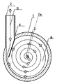
以下、図によって説明するにあたって、図1は本発明の器具の縦断面と構成の説明図で、液体導入口(2)から、揚程1m・20l/min.のポンプか、同程度で、液体を圧入させ、円形凹レンズ様の内室(B)で、整流リード弁(4)により内壁円周部に乱れなく沿って旋回流を形成させ、流速を加速させて、液体噴出孔(3)から外部に、笠状の旋回噴出流(C)を形成させて、気体導入管(5)から自給で、気体を取り入れ、気体の流量調整バルブ(6)で気圧、水圧等の外部要因で変化する微細気泡の径を調節し、気体を気体導入用の細管の束(7b)で、噴出孔(3)まで導き、細管の筒先(8b)を、適切な角度と位置で、笠状の旋回噴出流に差し込んで、剥離による大きな圧力勾配を得て、細管の筒先より円滑に気体を引き抜き、霧吹き作用を起こす。霧吹き作用を効率良く起こすためには、剥離点を特定する必要がある。
細管の筒先より引き抜かれた気体は、気泡と成り、自由剪断流である笠状の旋回噴出流に混じり、分断、粉砕されて、微細気泡に成っていき、笠状の旋回噴出流は、微細気泡を含んだ気液混合液の噴出流と成って、外部に噴出する。In the following, with reference to the drawings, FIG. 1 is an explanatory view of the longitudinal section and configuration of the instrument of the present invention. From the liquid inlet (2), the head is 1 m · 20 l / min. With the same level of pump, the liquid is pressed in, and a circular concave lens-like inner chamber (B) forms a swirling flow along the inner wall circumference without disturbance by the rectifying reed valve (4), thereby accelerating the flow velocity. Then, a cap-shaped swirling jet flow (C) is formed outside from the liquid jet hole (3), the gas is taken in from the gas introduction pipe (5), and the air pressure is adjusted by the gas flow control valve (6). Adjust the diameter of the fine bubbles that change due to external factors such as water pressure, guide the gas to the ejection hole (3) with the bundle of thin tubes for gas introduction (7b), and place the tube tip (8b) of the narrow tube at an appropriate angle. At this position, it is inserted into a whirling swirl jet flow to obtain a large pressure gradient due to separation, and the gas is smoothly drawn out from the end of the tube of the narrow tube to cause a spraying action. In order to efficiently cause the spraying action, it is necessary to specify the peeling point.
The gas withdrawn from the tube tip of the narrow tube becomes bubbles and is mixed with the free flowing shear-shaped swirling jet flow, divided and pulverized into fine bubbles. It becomes a jet flow of gas-liquid mixture containing bubbles and jets to the outside.
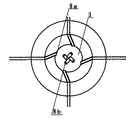
図2は、器具の横断面で、矢印で液体の流れ(D)を現わした。液体導入口(2)から液体を取り入れ、整流リード弁(4)で内壁円周部に乱れなく沿って、円形凹レンズ様の内室(B)に自由渦である旋回流を形成させ、円形凹レンズ様の内室の中心部で液体を加圧し、流速を加速して、噴出孔(3)から外部に笠状の旋回噴出流にして噴出させる。また、気体導入用の細管の束(7b)は、向心力によってでき、なおかつ、大きな気泡になりやすい気柱の発生の妨げになる。 FIG. 2 is a cross-sectional view of the instrument, and the flow of liquid (D) is indicated by an arrow. The liquid is taken in from the liquid inlet (2), and the rectifying reed valve (4) forms a swirl flow as a free vortex in the inner chamber (B) of the circular concave lens along the inner wall circumferential portion without being disturbed. The liquid is pressurized at the center of the inner chamber, the flow velocity is accelerated, and the mixture is ejected from the ejection hole (3) as a whirling swirl jet flow. Further, the bundle of thin tubes for introducing gas (7b) is formed by centripetal force, and further hinders the generation of air columns that tend to be large bubbles.
図3は、器具の中心部にある噴出孔(3)付近の部分断面で、円形凹レンズ様の内室(B)で加圧、加速された液体が、噴出孔(3)から、装置の外部の液体中(E)に笠状の旋回噴出流(C)を噴出させる、気体を気体導入用の細管(7a)、細管の束(7b)で、噴出孔(3)まで導き、細管の筒先(8a)を笠状の旋回噴出流の笠状の外側から差し込み、霧吹き作用を起こさせる。また、細管の束の筒先(8b)を笠状の旋回噴出流の笠状の内側より差し込んだ場合には、笠状の内側に発生する強制渦(G)の作用により中心部に圧力勾配が起こり、気体導入用の細管の筒先(8b)より、気体を引き抜く力が強まる、また、外部より強制渦の中心部へ吸引された、
![]()
![]()
図4は、器具の中心部にある噴出孔(3)付近を外部から見た図で、噴出孔(3)と笠状の旋回噴出流に適切な角度と位置で外側、内側から差し込んだ、気体導入用の細管の筒先(8a)(8b)を現わした。 FIG. 4 is a view of the vicinity of the ejection hole (3) in the center of the instrument as viewed from the outside, and is inserted from the outside and inside at an appropriate angle and position into the ejection hole (3) and the cap-shaped swirling ejection flow. The tube tips (8a) and (8b) of the thin tube for introducing gas were shown.
1 円筒型の胴の本体
2 液体導入口
3 噴出孔
4 整流リード弁
5 気体導入管
6 気体の流量調整バルブ
7a 笠状の旋回噴出流の外側から差し込む気体導入用の細管
7b 笠状の旋回噴出流の内側から差し込む気体導入用の細管の束
8a 笠状の旋回噴出流の外側から差し込む気体導入用の細管の筒先
8b 笠状の旋回噴出流の内側から差し込む気体導入用の細管の束の筒先
A 揚程1m・20l/min.のポンプか、同程度で、液体を圧入させた流れ
B 円形凹レンズ様の内室
C 笠状の旋回噴出流
D 円形凹レンズ様の内室の中の液体の流れ
E 装置の外部の液体の中
F 外部より強制渦の中心部へ吸引された流れ
G 笠状の内側に発生する強制渦DESCRIPTION OF
Claims (7)
Priority Applications (1)
| Application Number | Priority Date | Filing Date | Title |
|---|---|---|---|
| JP2006102428A JP2007237155A (en) | 2006-03-07 | 2006-03-07 | Microbubble generator |
Applications Claiming Priority (1)
| Application Number | Priority Date | Filing Date | Title |
|---|---|---|---|
| JP2006102428A JP2007237155A (en) | 2006-03-07 | 2006-03-07 | Microbubble generator |
Publications (1)
| Publication Number | Publication Date |
|---|---|
| JP2007237155A true JP2007237155A (en) | 2007-09-20 |
Family
ID=38583218
Family Applications (1)
| Application Number | Title | Priority Date | Filing Date |
|---|---|---|---|
| JP2006102428A Pending JP2007237155A (en) | 2006-03-07 | 2006-03-07 | Microbubble generator |
Country Status (1)
| Country | Link |
|---|---|
| JP (1) | JP2007237155A (en) |
Cited By (1)
| Publication number | Priority date | Publication date | Assignee | Title |
|---|---|---|---|---|
| JP2010207678A (en) * | 2009-03-09 | 2010-09-24 | Noritz Corp | Swirling type bubble generator |
-
2006
- 2006-03-07 JP JP2006102428A patent/JP2007237155A/en active Pending
Cited By (1)
| Publication number | Priority date | Publication date | Assignee | Title |
|---|---|---|---|---|
| JP2010207678A (en) * | 2009-03-09 | 2010-09-24 | Noritz Corp | Swirling type bubble generator |
Similar Documents
| Publication | Publication Date | Title |
|---|---|---|
| JP6169749B1 (en) | Microbubble generator | |
| JP6487041B2 (en) | Atomizer nozzle | |
| WO2021259349A1 (en) | Air-assisted electrostatic ultrasonic atomization spray nozzle and method | |
| JP6310359B2 (en) | Microbubble generator and method for generating the same | |
| JP6210846B2 (en) | Micro bubble spray device | |
| RU2329873C2 (en) | Liquid sprayer | |
| JP2008086868A (en) | Microbubble generator | |
| CN104772242B (en) | Atomizer | |
| KR20170104351A (en) | Apparatus for generating micro bubbles | |
| JP5080789B2 (en) | Nozzle device and method for forming atomization mechanism thereof | |
| JP2008136931A (en) | Liquid discharge apparatus | |
| CN104759372A (en) | Vortex street atomizing nozzle | |
| JP4426612B2 (en) | Fine bubble generation nozzle | |
| JP6714651B2 (en) | Gas-liquid mixing device | |
| JP2007069071A (en) | Minute bubble generator and minute bubble circulation system incorporated with it | |
| JP2008036612A (en) | Apparatus for aerial spraying of gas-liquid mixture containing high-density microbubbles | |
| KR101667492B1 (en) | Apparatus for generating micro bubbles | |
| JP6449531B2 (en) | Microbubble generator | |
| KR20170096674A (en) | micro-bubble generator | |
| WO2018151171A1 (en) | Bubble generating device for sewage purification | |
| JP2007237155A (en) | Microbubble generator | |
| JP2019166493A (en) | Fine bubble generation nozzle | |
| KR102305212B1 (en) | Bubble generator | |
| JP2009106918A (en) | Fine bubble generator | |
| JP2000300975A (en) | Gas-liquid mixing nozzle |