JP2007236281A - Noodle-producing equipment - Google Patents
Noodle-producing equipment Download PDFInfo
- Publication number
- JP2007236281A JP2007236281A JP2006063380A JP2006063380A JP2007236281A JP 2007236281 A JP2007236281 A JP 2007236281A JP 2006063380 A JP2006063380 A JP 2006063380A JP 2006063380 A JP2006063380 A JP 2006063380A JP 2007236281 A JP2007236281 A JP 2007236281A
- Authority
- JP
- Japan
- Prior art keywords
- outer cylinder
- noodle
- screw outer
- screw
- making apparatus
- Prior art date
- Legal status (The legal status is an assumption and is not a legal conclusion. Google has not performed a legal analysis and makes no representation as to the accuracy of the status listed.)
- Withdrawn
Links
Images


Abstract
Description
本発明は、職人の手を借りることなく、自動で高純度の蕎麦麺等を製造することができる製麺装置の技術に関する。 The present invention relates to a technology for a noodle making apparatus that can automatically produce high-purity soba noodles and the like without the assistance of a craftsman.
従来、自動で蕎麦麺等を製造することができる製麺装置の技術は公知となっている。しかし、蕎麦麺の材料となる蕎麦粉は粘りが少ないため、蕎麦麺を製造する際にはつなぎとして小麦粉やヤマノイモ等を添加する必要があった。
近年では、熟練した蕎麦職人の手を借りることなく、蕎麦粉の含有率が高い蕎麦麺(例えば、十割蕎麦等。)を製造するべく、スクリューを利用して高圧力で蕎麦粉をこねつつ押出し成形する蕎麦麺製造装置が公知となっている(例えば、特許文献1参照)。
In recent years, while producing buckwheat noodles (for example, ten percent buckwheat noodles) with a high content of buckwheat flour without the help of skilled buckwheat craftsmen, An apparatus for producing soba noodles by extrusion molding is known (for example, see Patent Document 1).
しかし、上記特許文献1に記載の製麺機においては、高圧力で蕎麦粉をこねつつ押出し成形を行なうため、スクリュー部分周辺の構造を頑丈なものとする必要があり、頻繁にスクリュー外筒の内周やスクリュー保持部等の洗浄やメンテナンスを行ない難い構成となっていた。食品製造装置においては、衛生面のメンテナンス性の向上は非常に重要である。
そこで、本発明が解決しようとする課題は、容易にスクリュー外筒の内周等の洗浄やメンテナンスを行なうことができる製麺装置を提供することにある。
However, in the noodle making machine described in Patent Document 1, it is necessary to make the structure around the screw portion sturdy because the extrusion is performed while kneading the buckwheat flour at a high pressure. It was difficult to clean and maintain the inner circumference and screw holding part. In food production equipment, improvement of hygiene maintenance is very important.
Therefore, the problem to be solved by the present invention is to provide a noodle making apparatus that can easily clean and maintain the inner periphery of the screw outer cylinder.
本発明の解決しようとする課題は以上の如くであり、次にこの課題を解決するための手段を説明する。 The problem to be solved by the present invention is as described above. Next, means for solving the problem will be described.
即ち、請求項1においては、穀物粉を混合する攪拌部と、混合された穀物粉をこねつつ、該穀物粉を押出して蕎麦麺等を成形する押出し部と、該攪拌部や押出し部を駆動するための駆動源が配設された本体と、を有する製麺装置であって、該押出し部が、スクリューと、該スクリューを覆う前スクリュー外筒及び後スクリュー外筒と、混合された穀物粉が通過する麺成形型等とを備え、該後スクリュー外筒を本体に固設し、該前スクリュー外筒の後端部に外側に向かって外フランジを形成し、前記本体に固設された該後スクリュー外筒の側面にレバーを枢支し、該レバーに抑え部材を固設し、該抑え部材と該後スクリュー外筒との間に該外フランジを挟むことによって、該前スクリュー外筒を該後スクリュー外筒に着脱自在に連結するものである。 That is, in claim 1, the stirring unit for mixing the grain flour, the extrusion unit for extruding the grain flour to form the noodles and the like while kneading the mixed grain flour, and driving the stirring unit and the extrusion unit A noodle making apparatus having a drive source disposed therein, wherein the extruded portion includes a screw, a front screw outer cylinder and a rear screw outer cylinder covering the screw, and mixed grain flour The rear screw outer cylinder is fixed to the main body, an outer flange is formed outwardly at the rear end portion of the front screw outer cylinder, and is fixed to the main body. The front screw outer cylinder is supported by pivotally supporting a lever on a side surface of the rear screw outer cylinder, fixing a holding member to the lever, and sandwiching the outer flange between the holding member and the rear screw outer cylinder. Which is detachably connected to the outer screw cylinder. That.
請求項2においては、前記前スクリュー外筒の先端部に内側に向って内フランジを形成し、前記麺成形型を、該内フランジの直後に配設したものである。 According to a second aspect of the present invention, an inner flange is formed inwardly at a front end portion of the front screw outer cylinder, and the noodle mold is disposed immediately after the inner flange.
請求項3においては、前記麺成形型が磁性体から構成され、該磁性体の表面にフッ素樹脂加工が施されたものである。 According to a third aspect of the present invention, the noodle mold is made of a magnetic material, and the surface of the magnetic material is processed with a fluororesin.
請求項4においては、前記麺成形型の周辺部のみに麺成形孔を穿孔し、中央部には麺成形孔を穿孔しないものである。 According to a fourth aspect of the present invention, the noodle forming hole is punched only in the peripheral part of the noodle forming mold, and the noodle forming hole is not punched in the central part.
本発明の効果として、以下に示すような効果を奏する。 As effects of the present invention, the following effects can be obtained.
請求項1においては、前スクリュー外筒を後スクリュー外筒に強固に固設しつつ、レバーの回動だけで容易に前スクリュー外筒を後スクリュー外筒から取り外すことができるため、スクリュー外筒の内周等の洗浄やメンテナンスを頻繁に行なうことができる。また、麺成形型の交換が容易であり、1台の製麺装置により種々の麺に対応可能となる。 According to the first aspect of the present invention, the front screw outer cylinder can be easily detached from the rear screw outer cylinder by simply rotating the lever while firmly fixing the front screw outer cylinder to the rear screw outer cylinder. It is possible to frequently perform cleaning and maintenance of the inner periphery of the garment. Further, the noodle mold can be easily exchanged, and various noodles can be handled by a single noodle making apparatus.
請求項2においては、スクリュー外筒内の穀物粉が高圧力となり、該穀物粉によって麺成形型が前方に押されても、該麺成形型の周端が前スクリュー外筒の内フランジ背面に当接するため、該麺成形型が前スクリュー外筒から外れることがない。 In claim 2, even if the grain flour in the screw outer cylinder becomes a high pressure and the noodle mold is pushed forward by the grain flour, the peripheral end of the noodle mold is located on the back of the inner flange of the front screw outer cylinder. Because of the contact, the noodle mold does not come off the front screw outer cylinder.
請求項3においては、磁石等を用いることによって、前スクリュー外筒から後方へと容易に麺成形型を取り外すことができる。 In claim 3, by using a magnet or the like, the noodle mold can be easily removed backward from the front screw outer cylinder.
請求項4においては、スクリューによって、麺成形型の周辺部のみから穀物粉を高圧力で押出すことができ、麺成形型の中央部からは穀物粉が押出されないため、低圧力で蕎麦麺等が押出されてくることがない。加えて、麺成形型に穿孔する麺成形孔の数を減らすことができるため、麺成形型自体や製麺装置自体の製造コストを低減させることができる。 In claim 4, since the grain flour can be extruded at a high pressure only from the periphery of the noodle mold by the screw and the grain flour is not extruded from the central portion of the noodle mold, Will not be extruded. In addition, since the number of noodle forming holes perforated in the noodle forming mold can be reduced, the manufacturing cost of the noodle forming mold itself and the noodle making apparatus itself can be reduced.
次に、発明の実施の形態を説明する。
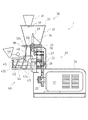
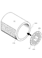
図1は本発明の一実施例を示す製麺装置1の前方斜視図、図2は同じく正面図、図3は同じく側面断面図、図4は前スクリュー外筒44を後スクリュー外筒43に連結した状態を示す前方斜視図、図5はレバー50を解除した状態のスクリュー外筒43・44を示す前方斜視図、図6は前スクリュー外筒44と麺成形型45の平面断面図、図7は麺成形型45と前スクリュー外筒44とを示す後方斜視図である。
Next, embodiments of the invention will be described.
FIG. 1 is a front perspective view of a noodle making apparatus 1 showing an embodiment of the present invention, FIG. 2 is a front view of the same, FIG. 3 is a side sectional view of the same, and FIG. FIG. 5 is a front perspective view showing the screw
本発明に係る製麺装置1にて製造される蕎麦麺等は、蕎麦・うどん・ラーメン等の麺類全般を言うものとし、蕎麦粉から製造される蕎麦麺に限定するものではなく、製麺装置1は蕎麦麺を製造する装置のみに限定するものではない。
但し、本発明は、スクリューを使用して高圧力で成形される麺類等の製造装置において、顕著な効果を奏するものである。
The soba noodles and the like produced by the noodle making apparatus 1 according to the present invention refer to all noodles such as soba noodles, noodles and ramen, and are not limited to the soba noodles produced from the soba flour. 1 is not limited only to the apparatus which manufactures soba noodles.
However, the present invention has a remarkable effect in an apparatus for producing noodles and the like molded at high pressure using a screw.
以下、本発明の製麺装置1の構成について詳述する。
図1乃至図3に示すように、製麺装置1は、駆動源21や駆動力伝達機構25・26・・・等が収容される本体20と、蕎麦粉や小麦粉や水分等(以下、穀物粉と言う。)を攪拌して混合する攪拌部30と、混合された穀物粉を高圧力でこねつつ蕎麦麺等の形状に成形して外部に押出す押出し部40等から構成されるものである。
Hereinafter, the configuration of the noodle making apparatus 1 of the present invention will be described in detail.
As shown in FIGS. 1 to 3, the noodle making apparatus 1 includes a
図3に示すように、本体20は上部ハウジング23及び下部ハウジング24によって被覆されるものであり、両ハウジング23・24同士は溶接やボルト締め等によって連結されている。
該下部ハウジング24内には、モータ21等の駆動源や下部ギア25等が収容されており、モータ21で得られた駆動力が上部ハウジング23内へと伝達されている。上部ハウジング23内には、該下部ギア25と噛合する中部ギア26が枢支されており、該中部ギア26の回動軸の前端には、後述するスクリュー42の心棒42bの後端部が着脱自在に嵌入(例えば、スプライン嵌合等。)されている。即ち、本実施例においては、中部ギア26の回動軸と心棒42bとが、同軸上に着脱自在に配設される構成となっている。
そして、該中部ギア26に伝達された駆動力は、該回動軸・上部ギア27・ベベルギア28・29等を介して、攪拌部30の攪拌軸33へと伝達される。
As shown in FIG. 3, the
In the
The driving force transmitted to the
攪拌部30は、前記上部ハウジング23の上方に配設されるものであり、水が投入される水用ホッパー31と、蕎麦粉や小麦粉等が投入されるホッパー32と、該ホッパー32内の穀物粉を攪拌して混合する攪拌軸33及び攪拌羽根34等から構成されている。
詳しくは、該ホッパー32の底面32bが溶接等によって前記上部ハウジング23の上面に固設されており、該攪拌軸33は前記モータ21から前記ギア26・27・・・等を介して伝達される駆動力によって回動される。該ホッパー32の上部は蓋35で覆われており、該蓋35の上方に水用ホッパー31が固設されている。該水用ホッパー31の下面には水分供給ノズル37が配設され、水用ホッパー31内の水分は、該水分供給ノズル37を通って少しずつホッパー32内へと落下する。
The stirring
Specifically, the
該攪拌軸33には攪拌羽根34が固設されており、攪拌軸33と共に回動する該該攪拌羽根34によってホッパー32内の穀物粉が攪拌されて混合される。そして、ホッパー底面32bの上部ハウジング23前方部分には、混合された穀物粉をホッパー32から後述する押出し部40へと落下させる穀物粉投下孔32cが形成されており、該ホッパー底面32bには該投下孔32cを開閉するためのシャッター38が摺動可能に配設されている。
以上の構成により、ホッパー32内で穀物粉が十分に攪拌・混合されたときに、作業者がシャッター38を引き抜けば、攪拌・混合された状態の穀物粉が、該投下孔32cからホッパー32下方の穀物粉投下筒48へと落下していく。
A stirring
With the above configuration, when the grain powder is sufficiently stirred and mixed in the
図3及び図4に示すように、押出し部40は、上部ハウジング23の前方に配設されるものであり、主に、後スクリュー外筒43と、前スクリュー外筒44と、該スクリュー外筒43・44に内包されるスクリュー42と、該前スクリュー外筒44内部に配設される麺成形型45と、粉振り器46とから構成されるものである。
前述した様に、該スクリュー42は、その回動軸である心棒42bが上部ハウジング23に収容される中部ギア26の回動軸前端に嵌合されており、前記モータ21等で得られた駆動力によって回動される。該心棒42bの周囲にはスクリュー羽根42cが形成されており、回動するスクリュー羽根42cによって穀物粉をこねつつ前方へと押し進める。
As shown in FIGS. 3 and 4, the pushing
As described above, the
そして、後スクリュー外筒43は、後端部の左右両側にフランジ43b・43bが形成されており、ボルト等により該フランジ43b・43bを上部ハウジング23の正面に固設することによって、該後スクリュー外筒43が上部ハウジング23の正面に固設されている。該スクリュー外筒43は、正面と背面に前記スクリュー42が貫通するための開口部が形成され、上面に前記攪拌部30から穀物粉が投下されるための開口部が形成され、略筒状に構成されている。後スクリュー外筒43の上方には、混合された穀物粉が通過してくる穀物粉投下筒48が固設されており、該上面の開口部と連通されている。
The rear screw
後スクリュー外筒43の前方には、前スクリュー外筒44が着脱自在に連結されており、前スクリュー外筒44後端部の内周形状が該後スクリュー外筒43前端部の内周形状と略一致するように形成されている。
図6に示すように、該前スクリュー外筒44の内周は、テーパが形成されて前方に向って徐々に内径が小さくなるように構成されており、前記スクリュー羽根42cの外径も、該前スクリュー外筒44の内周形状と同様に前方に向って徐々に外径が小さくなるように形成されている。
A front screw
As shown in FIG. 6, the inner periphery of the front screw
以下、前スクリュー外筒44と後スクリュー外筒43との連結構造について説明する。
前スクリュー外筒44と後スクリュー外筒43とは、レバー50によって着脱自在に連結されるものである。図4及び図5に示すように、前スクリュー外筒44の後端部には左右両側に外フランジ44b・44bが形成されており、後スクリュー外筒43の両側壁にはそれぞれ回動支持部49・49を介してレバー50が枢支されている。レバー50は回動軸50bと握持部50cとが直角に溶接されて構成されるものであり、該回動軸50bの中部及び後部が前記回動支持部49・49に枢支されて、該回動軸50bの前端部には正面視楕円形状の抑え部材51が固設されている。
Hereinafter, a connection structure between the front screw
The front screw
以上の構成により、図4に示すように、前スクリュー外筒44を後スクリュー外筒43に密接させた状態において、作業者が握持部50cを掴んでレバー50を正面視時計方向に回動すると、該回動軸50bを中心に抑え部材51が回動する。このとき、抑え部材51の背面によって外フランジ44bの正面が後方へ押付けられ、即ち、抑え部材51背面と後スクリュー外筒43正面との間に外フランジ44bが挟み込まれ、前スクリュー外筒44が後スクリュー外筒43に強固に連結される。逆に、図5に示すように、作業者がレバー50を正面視半時計方向に回動すると、抑え部材51背面による外フランジ44b正面の抑えが解除され、前スクリュー外筒44と後スクリュー外筒43との連結が解除される。
以上のスクリュー外筒43・44の連結機構は、スクリュー外筒43・44の左右両端に設けられている。
With the above configuration, as shown in FIG. 4, in a state where the front screw
The connection mechanism of the screw
このように、穀物粉を混合する攪拌部30と、混合された穀物粉をこねつつ、該穀物粉を押出して蕎麦麺等を成形する押出し部40と、該攪拌部30や押出し部40を駆動するための駆動源21が配設された本体20と、を有する製麺装置1であって、該押出し部40が、スクリュー42と、該スクリュー42を覆う前スクリュー外筒44及び後スクリュー外筒43と、混合された穀物粉等が通過する麺成形型45等とを備え、該後スクリュー外筒43を本体に固設し、該前スクリュー外筒44の後端部に外側に向かって外フランジ44bを形成し、前記本体20に固設された該後スクリュー外筒43の側面にレバー50を枢支し、該レバー50に抑え部材51を固設し、該抑え部材51と該後スクリュー外筒43との間に該外フランジ44bを挟むことによって、該前スクリュー外筒44を該後スクリュー外筒43に着脱自在に連結するので、前スクリュー外筒44を後スクリュー外筒43に強固に固設しつつ、レバー50の回動だけで容易に前スクリュー外筒44を後スクリュー外筒43から取り外すことができるため、スクリュー外筒43・44の内周等の洗浄やメンテナンスを頻繁に行なうことができる。また、成形型の交換が容易であり、1台の製麺装置により種々の麺に対応可能となる。
In this way, the
図6に示すように、前スクリュー外筒44の内周に形成されたテーパは、後部から中部にかけて形成されており、前スクリュー外筒44の前端部には、内側に向って内フランジ44cが形成されている。そして、前スクリュー外筒44内には、穀物粉が成形されつつ押出されるための麺成形型45が配設される。
該麺成形型45はステンレスや鋼等の磁性体によって構成されるものであり、穀物粉が押出されるノズルとしての役割を果たすものである。前スクリュー外筒44前端、即ち内フランジ44c直後の内径と略一致する外径を有する円盤形状に形成されており、該円盤の表面にはフッ素樹脂加工が施されている。
As shown in FIG. 6, the taper formed on the inner periphery of the front screw
The
図6及び図7に示すように、該麺成形型45は、前スクリュー外筒44を後スクリュー外筒43に連結する前に、後方から前スクリュー外筒44内部に嵌入されるものである。詳しくは、麺成形型45が、内フランジ44cの背面に当接した状態で、前スクリュー外筒44の内周に挟まれて保持される。そして、該麺成形型45を該前スクリュー外筒44から取り外す際には、先端に磁石53等の強力な磁性体が固設されたスティック47等によって容易に引き出せるようになっている。
As shown in FIGS. 6 and 7, the
このように、前記前スクリュー外筒44の先端部に内側に向って内フランジ44cを形成し、前記麺成形型45を、該内フランジ44cの直後に配設したので、スクリュー外筒43・44内の穀物粉が高圧力となり、該穀物粉によって麺成形型45が前方に押されても、該麺成形型45の周端が前スクリュー外筒44の内フランジ44c背面に当接するため、該麺成形型45が前スクリュー外筒44から外れることがない。
Thus, since the inner flange 44c is formed inwardly at the front end portion of the front screw
また、前記麺成形型45を磁性体によって構成し、該磁性体の表面にフッ素樹脂加工を施したので、磁石53等を用いることによって、前スクリュー外筒44から後方へと容易に麺成形型45を取り外すことができる。
Further, since the
図3に戻って、蕎麦麺等の成形方法について説明する。
前記穀物粉投下筒48から投下してきた穀物粉は、回動するスクリュー羽根42cによってこねられつつ高圧で前方に送られて、麺成形型45から外部に押出される。該麺成形型45の上方には、粉振り器46が配設されており、麺成形型45から蕎麦麺等が押出されてくる際に蕎麦麺等同士が密着することがないように、該蕎麦麺等に打粉を振りかけることができる。
Returning to FIG. 3, a method for forming soba noodles and the like will be described.
The cereal flour dropped from the cereal
そして、図6及び図7に示すように、該麺成形型45には、高圧の穀物粉が押出される際に通過する麺成形孔45b・45b・・・が形成されている。該麺成形孔45b・45bは鋼製等の麺成形型45にレーザー等によって形成されるものであるが、図6及び図7に示すように、該麺成形孔45b・45b・・・は麺成形型45の周辺部分(外周部分)にのみ形成されており、麺成形型45の中央部45cには貫通孔が形成されていない。これは、スクリュー42によって押し出されてくる蕎麦麺等は、主にスクリュー羽根42cが形成されている部分の前方に形成された麺成形孔45b・45b・・・から高圧力で押出され、心棒42bの前方に形成された麺成形孔45b・45b・・・からは少量の低圧力の蕎麦麺等しか押出されてこない点に鑑み、腰が弱い若しくは短い蕎麦麺等が形成されることを防止するためである。
As shown in FIGS. 6 and 7, the
このように、前記麺成形型45の周辺部のみに麺成形孔45b・45b・・・を穿孔し、中央部45cには麺成形孔45bを穿孔しないので、スクリュー42によって、麺成形型45の周辺部のみから穀物粉を高圧力で押出すことができ、麺成形型45の中央部45cからは穀物粉が押出されないため、低圧力で蕎麦麺等が押出されてくることがない。加えて、麺成形型45に穿孔する麺成形孔45b・45b・・・の数を減らすことができるため、麺成形型45自体や製麺装置1自体の製造コストを低減させることができる。
In this way, the
1 製麺装置
20 本体
21 駆動源
30 攪拌部
40 押出し部
42 スクリュー
43 後スクリュー外筒
44 前スクリュー外筒
44b 外フランジ
44c 内フランジ
45 麺成形型
45b 麺成形孔
45c 中央部
50 レバー
51 抑え部材
DESCRIPTION OF SYMBOLS 1
Claims (4)
混合された穀物粉をこねつつ、該混合された穀物粉を押出して麺状物を成形する押出し部と、
該攪拌部および押出し部を駆動する駆動源が配設された本体と、を有する製麺装置であって、
該押出し部が、スクリューと、該スクリューを覆う前スクリュー外筒及び後スクリュー外筒と、混合された穀物粉が通過する麺成形型とを備え、
該後スクリュー外筒を本体に固設し、
該前スクリュー外筒の後端部に外側に向かって外フランジを形成し、
該後スクリュー外筒の側面にレバーを枢支し、
該レバーに抑え部材を固設し、
該抑え部材と該後スクリュー外筒との間に該外フランジを挟むことによって、該前スクリュー外筒を該後スクリュー外筒に着脱自在に連結することを特徴とする製麺装置。 A stirring unit for mixing the flour,
An extruding section for extruding the mixed cereal flour to form a noodle-like product while kneading the mixed cereal flour;
A noodle making apparatus having a main body provided with a drive source for driving the stirring unit and the extrusion unit,
The extruding portion includes a screw, a front screw outer cylinder and a rear screw outer cylinder covering the screw, and a noodle forming die through which the mixed grain powder passes,
The screw outer cylinder is fixed to the main body,
Forming an outer flange toward the outside at the rear end of the front screw outer cylinder;
A lever is pivotally supported on the side of the rear screw outer cylinder,
A holding member is fixed to the lever,
A noodle making apparatus characterized in that the front screw outer cylinder is detachably connected to the rear screw outer cylinder by sandwiching the outer flange between the holding member and the rear screw outer cylinder.
前記麺成形型を、該内フランジの直後に配設したことを特徴とする請求項1に記載の製麺装置。 Forming an inner flange toward the inside at the tip of the front screw outer cylinder;
The noodle making apparatus according to claim 1, wherein the noodle forming die is disposed immediately after the inner flange.
Priority Applications (1)
| Application Number | Priority Date | Filing Date | Title |
|---|---|---|---|
| JP2006063380A JP2007236281A (en) | 2006-03-08 | 2006-03-08 | Noodle-producing equipment |
Applications Claiming Priority (1)
| Application Number | Priority Date | Filing Date | Title |
|---|---|---|---|
| JP2006063380A JP2007236281A (en) | 2006-03-08 | 2006-03-08 | Noodle-producing equipment |
Publications (1)
| Publication Number | Publication Date |
|---|---|
| JP2007236281A true JP2007236281A (en) | 2007-09-20 |
Family
ID=38582448
Family Applications (1)
| Application Number | Title | Priority Date | Filing Date |
|---|---|---|---|
| JP2006063380A Withdrawn JP2007236281A (en) | 2006-03-08 | 2006-03-08 | Noodle-producing equipment |
Country Status (1)
| Country | Link |
|---|---|
| JP (1) | JP2007236281A (en) |
Cited By (6)
| Publication number | Priority date | Publication date | Assignee | Title |
|---|---|---|---|---|
| WO2011052012A1 (en) | 2009-10-29 | 2011-05-05 | Sugano Eiji | Extrusion type noodle making machine |
| WO2013045059A1 (en) * | 2011-09-30 | 2013-04-04 | Thermo Electron (Karlsruhe) Gmbh | Extruder |
| JP2014103963A (en) * | 2012-11-22 | 2014-06-09 | Nihon Career Ind Co Ltd | Noodle making machine |
| JP2014221017A (en) * | 2013-05-13 | 2014-11-27 | タカノ株式会社 | Production method of buckwheat noodle, manufacturing apparatus of buckwheat noodle, and buckwheat noodle |
| CN107047674A (en) * | 2017-02-20 | 2017-08-18 | 刘魁 | The efficient flour stranding machine of one kind transmission |
| CN113287646A (en) * | 2021-05-25 | 2021-08-24 | 桂林市农业科学研究中心 | Processing device and processing method for corn noodles and corn dough sheets |
-
2006
- 2006-03-08 JP JP2006063380A patent/JP2007236281A/en not_active Withdrawn
Cited By (9)
| Publication number | Priority date | Publication date | Assignee | Title |
|---|---|---|---|---|
| WO2011052012A1 (en) | 2009-10-29 | 2011-05-05 | Sugano Eiji | Extrusion type noodle making machine |
| US8721314B2 (en) | 2009-10-29 | 2014-05-13 | Eiji Sugano | Noodle maker |
| WO2013045059A1 (en) * | 2011-09-30 | 2013-04-04 | Thermo Electron (Karlsruhe) Gmbh | Extruder |
| CN103906618A (en) * | 2011-09-30 | 2014-07-02 | 热电子(卡尔斯鲁厄)有限公司 | Extruder |
| DE102011114578B4 (en) | 2011-09-30 | 2024-02-15 | Thermo Electron (Karlsruhe) Gmbh | extruder |
| JP2014103963A (en) * | 2012-11-22 | 2014-06-09 | Nihon Career Ind Co Ltd | Noodle making machine |
| JP2014221017A (en) * | 2013-05-13 | 2014-11-27 | タカノ株式会社 | Production method of buckwheat noodle, manufacturing apparatus of buckwheat noodle, and buckwheat noodle |
| CN107047674A (en) * | 2017-02-20 | 2017-08-18 | 刘魁 | The efficient flour stranding machine of one kind transmission |
| CN113287646A (en) * | 2021-05-25 | 2021-08-24 | 桂林市农业科学研究中心 | Processing device and processing method for corn noodles and corn dough sheets |
Similar Documents
| Publication | Publication Date | Title |
|---|---|---|
| JP2007236281A (en) | Noodle-producing equipment | |
| JPH08104899A (en) | Multi-stage vacuum kneading and extrusion molding machine | |
| WO2014142136A1 (en) | Method for stirring and kneading food powder and device for stirring and kneading food powder | |
| CN202931973U (en) | Extrusion dough mixer | |
| JP7231174B2 (en) | extruder | |
| JP5957090B2 (en) | Granulator | |
| CN201451179U (en) | Multifunctional machine for making dough drops and noodles with fillings | |
| US20160114515A1 (en) | Kneading and granulating apparatus | |
| JP7266882B2 (en) | granulator | |
| JP3189551U (en) | Connecting device for screw mixer of noodle making machine | |
| CN215428352U (en) | Prevent powder mixer of casting of layering | |
| JPH07504600A (en) | Machines and equipment that enable separation operations for kneading homemade dough or paste and extruding the edible dough or paste, as well as mincing meat, etc. | |
| WO2016002333A1 (en) | Biaxial extruder | |
| TWI450688B (en) | Flour mixer and noodle machine comprising the same | |
| JP2011188763A (en) | Mixer for noodle dough | |
| KR101528705B1 (en) | pill machine for molding roller | |
| CN107253599B (en) | A kind of multisection type oil plant particle feed device | |
| JP2010279258A (en) | Bean jam-wrapping machine | |
| JP2004313165A (en) | Method for producing noodle and device for the same | |
| WO2016034596A1 (en) | A noodle making machine | |
| JP2003144040A (en) | Noodle-making equipment for buckwheat | |
| JP6275550B2 (en) | Powdering method and dusting device | |
| TWM550993U (en) | Tapioca pearls making machine | |
| KR20180055229A (en) | Nozzle device for forming with Double Colors rice cake | |
| CN205833101U (en) | A kind of high-performance dry-process granulator |
Legal Events
| Date | Code | Title | Description |
|---|---|---|---|
| A300 | Withdrawal of application because of no request for examination |
Free format text: JAPANESE INTERMEDIATE CODE: A300 Effective date: 20090512 |