JP2007236148A - Motor - Google Patents
Motor Download PDFInfo
- Publication number
- JP2007236148A JP2007236148A JP2006056828A JP2006056828A JP2007236148A JP 2007236148 A JP2007236148 A JP 2007236148A JP 2006056828 A JP2006056828 A JP 2006056828A JP 2006056828 A JP2006056828 A JP 2006056828A JP 2007236148 A JP2007236148 A JP 2007236148A
- Authority
- JP
- Japan
- Prior art keywords
- magnetic steel
- steel plate
- press
- fitted
- magnetic
- Prior art date
- Legal status (The legal status is an assumption and is not a legal conclusion. Google has not performed a legal analysis and makes no representation as to the accuracy of the status listed.)
- Pending
Links
- 229910000831 Steel Inorganic materials 0.000 claims abstract description 167
- 239000010959 steel Substances 0.000 claims abstract description 167
- 230000002093 peripheral effect Effects 0.000 claims description 19
- 230000004907 flux Effects 0.000 description 37
- 238000004519 manufacturing process Methods 0.000 description 23
- 230000006872 improvement Effects 0.000 description 16
- 239000000463 material Substances 0.000 description 12
- XEEYBQQBJWHFJM-UHFFFAOYSA-N Iron Chemical compound [Fe] XEEYBQQBJWHFJM-UHFFFAOYSA-N 0.000 description 8
- 239000000696 magnetic material Substances 0.000 description 8
- 238000010438 heat treatment Methods 0.000 description 7
- 238000010030 laminating Methods 0.000 description 6
- 239000011248 coating agent Substances 0.000 description 5
- 238000000576 coating method Methods 0.000 description 5
- 229910052742 iron Inorganic materials 0.000 description 4
- 238000003475 lamination Methods 0.000 description 4
- 239000000843 powder Substances 0.000 description 4
- 230000002708 enhancing effect Effects 0.000 description 3
- 230000035699 permeability Effects 0.000 description 3
- 239000002184 metal Substances 0.000 description 2
- 229910052751 metal Inorganic materials 0.000 description 2
- 230000036316 preload Effects 0.000 description 2
- 230000009467 reduction Effects 0.000 description 2
- 229910000976 Electrical steel Inorganic materials 0.000 description 1
- 239000003822 epoxy resin Substances 0.000 description 1
- 230000010354 integration Effects 0.000 description 1
- 230000004048 modification Effects 0.000 description 1
- 238000012986 modification Methods 0.000 description 1
- 229920000647 polyepoxide Polymers 0.000 description 1
- 238000004080 punching Methods 0.000 description 1
- 125000006850 spacer group Chemical group 0.000 description 1
- 238000003466 welding Methods 0.000 description 1
Images


Landscapes
- Iron Core Of Rotating Electric Machines (AREA)
Abstract
Description
本発明は、コイルが巻回された積層コアを有するモータに関する。 The present invention relates to a motor having a laminated core around which a coil is wound.
コイルが巻回されたコアを有するモータの中には、コアの鉄損を小さくするために複数の磁性鋼板を積層した積層コアを採用する場合がある。この種のモータとして、特許文献1には、高回転での運転域と高トルクでの運転域とでの効率を高めるために、高透磁率低磁束密度の材料からなる磁性鋼板と低透磁率高磁束密度の材料からなる磁性鋼板とを積層して形成した積層コアを採用したモータが記載されている。 A motor having a core around which a coil is wound may employ a laminated core in which a plurality of magnetic steel plates are laminated in order to reduce core iron loss. As this type of motor, Patent Document 1 discloses a magnetic steel plate made of a material having a high magnetic permeability and a low magnetic flux density and a low magnetic permeability in order to increase the efficiency in an operating region at a high rotation and an operating region at a high torque. A motor employing a laminated core formed by laminating magnetic steel plates made of a material having a high magnetic flux density is described.
積層コアが磁気飽和に達すると予定の磁束が得られず、予定の出力トルクが得られなくなってしまうため、最大磁束密度ができるだけ高い磁性材料を用いて積層コアを形成することが望ましい。また、シャフトの回転数を上げるためにコイルに流れる電流の周波数を高くすると、積層コアでの渦電流損失は大きくなるため、周波数の上昇に伴う渦電流損失が小さい周波数特性を有する磁性材料を用いて積層コアを形成することが望ましい。しかしながら、最大磁束密度が高く且つ高周波数で渦電流損失の小さい特殊な磁性材料の素材が柔らかい場合、積層コアの鉄損を低減するために磁性鋼板を薄くしようとすると、磁性鋼板の加工時に変形し易くなり、また、磁性鋼板を積層するときに変形し易くなって積層コアの品質が低下し易くなる。また、特許文献1に記載の積層コアのように、磁性材料の異なる二種類の磁性鋼板を用いて積層コアを製作する場合には、磁性鋼板に熱処理を施すと各磁性鋼板の材質が異なるためにそれぞれ異なった変形をし、熱処理後に各磁性鋼板を積層して形成する積層コアの品質が低下する。そして、この品質低下がモータの回転精度を低下させる。 When the laminated core reaches magnetic saturation, a predetermined magnetic flux cannot be obtained and a predetermined output torque cannot be obtained. Therefore, it is desirable to form the laminated core using a magnetic material having a maximum magnetic flux density as high as possible. In addition, if the frequency of the current flowing through the coil is increased to increase the number of rotations of the shaft, the eddy current loss in the laminated core increases. Therefore, a magnetic material having a frequency characteristic in which the eddy current loss accompanying the increase in frequency is small is used. It is desirable to form a laminated core. However, if the material of a special magnetic material with a high maximum magnetic flux density and low eddy current loss at a high frequency is soft, an attempt to reduce the thickness of the magnetic steel sheet in order to reduce the core loss of the laminated core will cause deformation during processing of the magnetic steel sheet. In addition, it is easy to deform when laminating magnetic steel sheets, and the quality of the laminated core is liable to deteriorate. In addition, when a laminated core is manufactured using two types of magnetic steel plates having different magnetic materials, such as the laminated core described in Patent Document 1, the material of each magnetic steel plate is different when the magnetic steel plate is subjected to heat treatment. Thus, the quality of the laminated core formed by laminating the magnetic steel plates after the heat treatment is deteriorated. This reduction in quality lowers the rotation accuracy of the motor.
本発明は、積層コアの磁気特性の選択性を向上でき且つ回転精度を向上できるモータを提供することを目的とする。 An object of this invention is to provide the motor which can improve the selectivity of the magnetic characteristic of a lamination | stacking core, and can improve a rotation precision.
本発明は、積層コアにコイルが巻回されてなるモータにおいて、積層コアは、磁気特性の異なる二種以上の磁性鋼板のうち、一方の磁性鋼板に形成された単数または複数の凸部が他方の磁性鋼板に形成された単数または複数の連結孔にそれぞれ圧入されて一体になった単位コア部を、シャフトの回転軸線方向に沿って積層したことを特徴とする。 The present invention relates to a motor in which a coil is wound around a laminated core, and the laminated core has one or more protrusions formed on one magnetic steel plate among two or more types of magnetic steel plates having different magnetic properties. A unit core portion that is press-fitted into and integrated with one or a plurality of connecting holes formed in the magnetic steel plate is laminated along the rotation axis direction of the shaft.
このモータでは、磁気特性の異なる二種以上の磁性鋼板によって単位コア部を構成するため、磁性鋼板の組み合わせ方によって積層コアの最大磁束密度や周波数特性といった磁気特性を容易に変えることができ、積層コアの磁気特性の選択性を向上できる。さらに、最大磁束密度や周波数特性といった磁気特性は高いが機械的な剛性が低い磁性鋼板に、機械的な剛性が高い他の磁性鋼板を組み合わせて単位コア部を形成することもでき、単位コア部の磁気特性を高めつつ剛性を高めることが容易になる。特に、剛性の高められた単位コア部を利用して積層コアを形成するときに、単位コア部の歪みその他の変形が生じ難くなって積層コアの品質が向上する。さらに、単位コア部は、磁気特性の異なる二種以上の磁性鋼板のうち、一方の磁性鋼板に形成された凸部が他方の磁性鋼板に形成された連結孔にそれぞれ圧入されて一体になっており、熱処理を施しても歪みその他の変形を生じ難い。その結果として、歪みの少ない単位コア部が利用されるので、積層コアの品質を向上させることができる。そして、積層コアの品質向上がモータの回転精度向上に寄与する。さらに、磁気特性の高い高価な磁性鋼板に磁気特性の低い安価な磁性鋼板を組み合わせて単位コア部を形成することもできるため、一種類の磁性材料によって単位コア部を形成する場合に比べて、単位コア部の製作費を低く抑える一方で単位コア部の磁気特性を容易に向上させることができる。従って、積層コアの磁気特性の選択性を高めつつコストダウンを図ることも可能になる。 In this motor, the unit core part is composed of two or more types of magnetic steel plates with different magnetic properties, so the magnetic properties such as the maximum magnetic flux density and frequency characteristics of the laminated core can be easily changed by combining the magnetic steel plates. The selectivity of the magnetic properties of the core can be improved. Furthermore, a unit core part can be formed by combining a magnetic steel sheet with high magnetic characteristics such as maximum magnetic flux density and frequency characteristics but low mechanical rigidity with another magnetic steel sheet with high mechanical rigidity. It is easy to increase the rigidity while enhancing the magnetic characteristics of the. In particular, when a laminated core is formed using a unit core portion with increased rigidity, distortion of the unit core portion and other deformations are less likely to occur, and the quality of the laminated core is improved. Furthermore, the unit core part is integrally formed by press-fitting a convex part formed on one magnetic steel sheet into a connecting hole formed on the other magnetic steel sheet among two or more types of magnetic steel sheets having different magnetic properties. Therefore, even if heat treatment is performed, distortion and other deformations are unlikely to occur. As a result, since the unit core portion with less distortion is used, the quality of the laminated core can be improved. And the improvement of the quality of the laminated core contributes to the improvement of the rotation accuracy of the motor. Furthermore, since it is also possible to form a unit core part by combining an inexpensive magnetic steel sheet with high magnetic properties with an inexpensive magnetic steel sheet with low magnetic properties, compared to the case where the unit core part is formed with one type of magnetic material, It is possible to easily improve the magnetic characteristics of the unit core part while keeping the manufacturing cost of the unit core part low. Therefore, it is possible to reduce the cost while enhancing the magnetic property selectivity of the laminated core.
また、一方の磁性鋼板の中央には中空のボス部が形成され、他方の磁性鋼板の中央にはボス部の外周が圧入される円孔が形成されていると好適である。一方の磁性鋼板に形成されたボス部が他方の磁性鋼板の円孔に圧入されるので単位コア部の製作が容易になる。さらに、一方の磁性鋼板の中央に形成されたボス部の外周は、他方の磁性鋼板の中央に形成された円孔に圧入されるので、一方の磁性鋼板と他方の磁性鋼板との間での心出しが不要になる。 Further, it is preferable that a hollow boss portion is formed at the center of one magnetic steel plate, and a circular hole into which the outer periphery of the boss portion is press-fitted is formed at the center of the other magnetic steel plate. Since the boss portion formed on one magnetic steel plate is press-fitted into the circular hole of the other magnetic steel plate, the unit core portion can be easily manufactured. Furthermore, since the outer periphery of the boss part formed at the center of one magnetic steel sheet is press-fitted into a circular hole formed at the center of the other magnetic steel sheet, Centering becomes unnecessary.
また、シャフトの回転軸線方向に延在する筒状の周壁部を有するベース部を更に備え、一方の磁性鋼板には、外縁からシャフトの回転軸線方向に突出した筒状のボス部が形成され、ボス部の内周には、他方の磁性鋼板の外周が圧入され、ボス部の外周は周壁部の内周に圧入されると好適である。一方の磁性鋼板に形成されたボス部の内周に他方の磁性鋼板の外周が圧入されるので単位コア部の製作が容易になる。さらに、ベース部の周壁部の内周に単位コア部を圧入するに際し、一方の磁性鋼板と他方の磁性鋼板との間での心出しが不要になる。従って、複数の単位コア部を周壁部の内周に固定する際の精度向上と組立作業性向上とが両立する。 Further, it further includes a base portion having a cylindrical peripheral wall portion extending in the rotation axis direction of the shaft, and one magnetic steel plate is formed with a cylindrical boss portion protruding from the outer edge in the rotation axis direction of the shaft, It is preferable that the outer periphery of the other magnetic steel plate is press-fitted into the inner periphery of the boss part, and the outer periphery of the boss part is press-fitted into the inner periphery of the peripheral wall part. Since the outer periphery of the other magnetic steel plate is press-fitted into the inner periphery of the boss portion formed on one magnetic steel plate, the manufacture of the unit core portion is facilitated. Further, when the unit core portion is press-fitted into the inner periphery of the peripheral wall portion of the base portion, centering between one magnetic steel plate and the other magnetic steel plate is not necessary. Therefore, it is possible to achieve both improvement in accuracy and improvement in assembly workability when fixing the plurality of unit core portions to the inner periphery of the peripheral wall portion.
本発明によれば、積層コアの磁気特性の選択性を向上でき且つ回転精度を向上できる。 According to the present invention, the selectivity of the magnetic properties of the laminated core can be improved and the rotation accuracy can be improved.
以下、図面を参照して本発明に係るモータの好適な実施の形態について詳細に説明をする。 Hereinafter, preferred embodiments of a motor according to the present invention will be described in detail with reference to the drawings.
[第1の実施の形態]
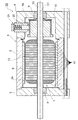
図1〜図3に示すように、モータ1Aは、小型のDCモータであり、金属製で円筒状の筺体2を有し、筺体2の開放された前端には、非磁性材によって形成された円盤状の前側ブラケット3が当接し、前側ブラケット3は筺体2にねじ止めされている。一方、筺体2の開放された後端には、樹脂製でカップ状の後側ブラケット4が、凹部4aを筺体2側に向けて当接し、後側ブラケット4は筺体2にねじ止めされている。筺体2、前側ブラケット3及び後側ブラケット4によってモータケース5が構成され、モータケース5内にマグネット6とロータ7とが収容されている。
[First embodiment]
As shown in FIGS. 1 to 3, the motor 1 </ b> A is a small DC motor, and has a metal-made
前側ブラケット3及び後側ブラケット4には、それぞれラジアル軸受8,9が圧入されており、前側ブラケット3及び後側ブラケット4を貫通して延在するシャフト10は、各ラジアル軸受8,9によって支持されている。ステータとしてのマグネット6は、筺体2の内壁面2aに接着されている。ロータ7は、マグネット6に包囲された積層コア13と、積層コア13に巻回されたコイル14と、コイル14に結線された整流子16とを有する。
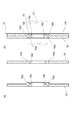
積層コア13は、シャフト10の回転軸線C1に沿って積層された複数の単位コア部17を有する。単位コア部17は、図4及び図5に示すように、打ち抜き加工することで形成された第1の磁性鋼板18と第2の磁性鋼板19とからなる。第1の磁性鋼板18は最大磁束密度が1.6T以上の高磁束密度軟磁性材料を用いて形成され、第2の磁性鋼板19は第1の磁性鋼板18よりも剛性が高く最大磁束密度が1.5T以下の珪素鋼材を用いて形成される。
The laminated
第1及び第2の磁性鋼板18,19の外周の輪郭は同一形状であり、周方向に並ぶ9本のポール部18a,19aは等間隔に配置されている。各ポール部18a,19a間の溝18b,19bは積層コア13のスロット13a(図3参照)になる。
The outer contours of the first and second
第1の磁性鋼板18の中央には中空円筒状のボス部18cが形成されている。ボス部18cの内径は、シャフト10の外径に対応しており、ボス部18c内にシャフト10が圧入される。第1の磁性鋼板18には、回転軸線C1の方向に突出する円柱状の凸部18dが三箇所に設けられている。各凸部18dは、ボス部18cを囲む同一円周上で且つ各凸部18dを直線で結ぶと正三角形となるように配置されている。
A hollow
第2の磁性鋼板19の中央には、ボス部18cの外径に対応した円孔19cが形成されており、この円孔19cの周りには、第1の磁性鋼板18の凸部18dが圧入される円形の連結孔19dが3個形成されている。第2の磁性鋼板19の円孔19cには、第1の磁性鋼板18のボス部18cの外周18fが圧入され、連結孔19d内に凸部18dが圧入されて、第2の磁性鋼板19は第1の磁性鋼板18と結合する。第1及び第2の磁性鋼板18,19は外周の輪郭がズレ無く重なり合って一体になり、第1の磁性鋼板18と第2の磁性鋼板19とで単位コア部17が構成される。
A
単位コア部17には熱処理が施される。その後、複数の単位コア部17は互いの輪郭がズレ無いように重ね合わせられ、図1及び図4に示すように、各ボス部18cの内側にシャフト10が圧入される。このようにして、複数の単位コア部17は、シャフト10の回転軸線C1に沿って積層され、積層コア13が形成される。そして、積層コア13を挟むようにして筒状の絶縁スペーサがシャフト10に圧入された後、積層コア13にエポキシ樹脂による絶縁粉体塗装が施される。シャフト10の後端側には、整流子16が接着される。コイル14は、積層コア13の9本のスロット13a(図3参照)を通り、ポール13bに巻回される。コイル14は整流子16に結線され、整流子16にはブラシ20が摺動接触する。ブラシ20はブラシホルダー21内に収容され、ブラシホルダー21は後側ブラケット4に固定されている。コイル14は、ブラシ20及び整流子16を介して通電され、マグネット6との協働によってシャフト10を回転させる。
The
モータ1Aの積層コア13は、複数の単位コア部17によって形成され、単位コア部17は、最大磁束密度の異なる二種類の磁性鋼板18,19の組み合わせによって形成される。その結果として、第1の磁性鋼板18と同じ材質の磁性鋼板のみを積層して積層コアを形成した場合に比べ、積層コア13の有する最大磁束密度のバリエーションが広がり、積層コア13の最大磁束密度に関する選択性が向上する。
The
特に、単位コア部17は、最大磁束密度は高いが剛性が低い第1の磁性鋼板18に最大磁束密度は低いが剛性が高い第2の磁性鋼板19を組み合わせることで、第1の磁性鋼板18の剛性を第2の磁性鋼板19で補い、第2の磁性鋼板19の最大磁束密度を第1の磁性鋼板18で補っており、単位コア部17の薄型化と単位コア部17の最大磁束密度の増加とを両立させている。その結果として、単位コア部17の薄型化による積層コア13の鉄損減少と、最大磁束密度の増加による出力トルクの増加とを両立させている。さらに、単位コア部17の剛性が高くなると、単位コア部17を搬送する際、または単位コア部17をシャフト10に圧入する際に、歪みその他の変形が生じ難くなる。
In particular, the
さらに、熱処理を施す場合、単位コア部17は、第1の磁性鋼板18と第2の磁性鋼板19との圧入結合による一体化により形成されているので、第1の磁性鋼板18や第2の磁性鋼板19に対して個別に熱処理を施す場合に比べて、歪みその他の変形を生じ難い。そして、歪みの少ない単位コア部17が利用される結果として、積層コア13の品質を向上できる。そして、積層コア13の品質向上がモータ1Aの回転精度向上に寄与する。
Further, when heat treatment is performed, the
なお、最大磁束密度の高い第1の磁性鋼板18の素材が最大磁束密度の低い第2の磁性鋼板19の素材よりも高価な場合、第1の磁性鋼板18と同一素材の磁性鋼板のみで積層コアを形成すると、最大磁束密度は高くなるが製作費が高くなってしまう。一方、第2の磁性鋼板19と同一素材の磁性鋼板のみで積層コアを形成すると、製作費を低く抑えることはできるが最大磁束密度が低下してしまう。そこで、本発明に係るモータ1Aでは、第1の磁性鋼板18と第2の磁性鋼板19とを組み合わせて単位コア部17を形成することで、単位コア部17の製作費を低く抑える一方で単位コア部17の最大磁束密度を向上させており、積層コア13の最大磁束密度の選択性を高めつつコストダウンを図っている。
When the material of the first
さらに、第1の磁性鋼板18の中央には、シャフト10が圧入される中空のボス部18cが形成され、第2の磁性鋼板19の中央には、ボス部18cが圧入される円孔19cが形成されている。従って、第1の磁性鋼板18のボス部18cが第2の磁性鋼板19の円孔19cに圧入されるので、単位コア部17の製作が容易になる。さらに、ボス部18cの内部にシャフト10を圧入するに際し、第1の磁性鋼板18と第2の磁性鋼板19との間での心出しが不要になる。従って、複数の単位コア部17をシャフト10に圧入する際の精度向上と組立作業性向上とが両立する。
Further, a
[第2の実施の形態]
第1の実施形態に係る単位コア部17は、二枚の磁性鋼板18,19によって形成されたが、図6及び図7に示すように、第2の実施形態に係る単位コア部22は、磁気特性の異なる三枚の磁性鋼板23〜25によって構成される。第2の実施形態は、単位コア部22を除いて第1の実施形態と共通するため、単位コア部22を中心に説明を行い、その他の構成については、図1に示す第1の実施形態と同一の符号を記して説明を省略する。
[Second Embodiment]
The
第1〜第3の磁性鋼板23,24,25の外周の輪郭は同一形状になっており、第1の実施形態に係る単位コア部17と同様に9本のポール部(図示せず)が形成されている。第1の磁性鋼板23の中央には、シャフト10に圧入される円筒状のボス部23aが設けられ、さらに、第1の磁性鋼板23には、回転軸線C1の方向に突出する円柱状の三本の凸部23bが形成されている。第2の磁性鋼板24の中央には、ボス部23aの外周23cが圧入される円孔24aが形成され、その円孔24aの周囲には、凸部23bが圧入される円形の連結孔24bが三個形成されている。同様に、第3の磁性鋼板25の中央にもボス部23aが圧入される円孔25aが形成され、その円孔25aの周囲には、凸部23bが圧入される円形の連結孔25bが三個形成されている。
The outer contours of the first to third
第2の磁性鋼板24の円孔24aには、第1の磁性鋼板23のボス部23aが圧入され、さらに、連結孔24bには凸部23bが圧入される。また、第3の磁性鋼板25の円孔25aには、第2の磁性鋼板24を貫通して突き出たボス部23aが圧入され、さらに、連結孔25bには第2の磁性鋼板24を貫通して突き出た凸部23bが圧入される。このようにして、第2及び第3の磁性鋼板24,25は、第1の磁性鋼板23にズレ無く重なり合って一体になり、第1〜第3の磁性鋼板23,24,25によって単位コア部22が構成される。単位コア部22は、モータ1Aと同様にシャフト10に圧入され、複数の単位コア部22がシャフト10の回転軸線C1方向に積層されて積層コア13(図1参照)が形成される。
The
単位コア部22は、最大磁束密度の異なる三種類の磁性鋼板23〜25の組み合わせによって形成され、その結果として、最大磁束密度のバリエーションが広がり、積層コア13の最大磁束密度に関する選択性が向上する。さらに、熱処理を施す場合、単位コア部22は三種類の磁性鋼板23〜25の圧入結合による一体化により、第1〜第3の磁性鋼板23,24,25に対して個別に熱処理を施す場合に比べて、歪みその他の変形を生じ難い。そして、歪みの少ない単位コア部22が利用される結果として、積層コア13の品質を向上できる。そして、積層コア13の品質向上がモータの回転精度向上に寄与する。
The
[第3の実施の形態]
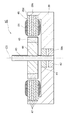
本発明に係るモータの第3の実施形態について説明する。図8に示すように、モータ1Bは小型のブラシレスモータであり、金属製のベース部27を有する。ベース部27の中央には円筒状のスリーブ27aが形成され、スリーブ27a内には、予圧ばね(図示せず)を挟むようにして上下2段となるラジアル軸受28,29が圧入されている。ラジアル軸受28,29によってシャフト30が支持されている。カップ状のロータヨーク部31は、凹部31aをスリーブ27a側に向けると共に、スリーブ27aを包囲するように配置されている。ロータヨーク部31の中央には、スリーブ27aの上端から突き出したシャフト30が固定されている。
[Third embodiment]
A third embodiment of the motor according to the present invention will be described. As shown in FIG. 8, the motor 1 </ b> B is a small brushless motor and has a
スリーブ27aの外周には積層コア32が圧入され、積層コア32の外周に形成されたポール(図示せず)にはコイル33が巻回されている。ロータヨーク部31の内壁面には、積層コア32を包囲するようにしてマグネット34が接着されている。ベース部27上で且つ積層コア32の下方にはホール素子が取り付けられた回路基板(図示せず)が固定されている。そして、コイル33への通電によってマグネット34が回転し、マグネット34の磁極をホール素子が検出してコイル33への通電が切り替わり、シャフト30が一方向に回転する。
A
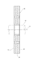
積層コア32は、シャフト30の回転軸線C2方向に沿って積層された複数の単位コア部35によって形成される。そして、図9に示すように、単位コア部35は最大磁束密度の高い第1の磁性鋼板36と最大磁束密度は低いが剛性の高い第2の磁性鋼板37とによって形成される。第1の磁性鋼板36の中央には、スリーブ27aに圧入される円孔36aが形成されている。さらに、第1の磁性鋼板36には、円孔36aの外縁に沿って回転軸線C2の方向に突出する中空円筒状のボス部36cが形成されている。一方、第2の磁性鋼板37の中央には、第1の磁性鋼板36のボス部36cの外径に対応した円孔37aが形成されている。
The
さらに、第1の磁性鋼板36には円孔36aの周囲に三個の凸部36bが形成され、第2の磁性鋼板37には、凸部36bが圧入される三個の連結孔37bが形成されている。第2の磁性鋼板37の連結孔37bには、第1の磁性鋼板36の凸部36bが圧入されて、第2の磁性鋼板37は第1の磁性鋼板36と結合する。第1及び第2の磁性鋼板36,37は外周の輪郭がズレ無く重なり合って一体になり、第1の磁性鋼板36と第2の磁性鋼板37とで単位コア部35が構成される。複数の単位コア部35は筒状の積層コア製造用スリーブ38に緩やかに圧入されて積層される。積層コア製造用スリーブ38の外径は、ベース部27のスリーブ27a(図8参照)の外径に対応している。
Further, the first
積層コア32を製造する際に利用されるスリーブ38にはフランジ38aが形成されており、最初に圧入される単位コア部35は、フランジ38aに当接するまで挿入され、その後、他の単位コア部35が順次軽圧入される。このようにして、複数の単位コア部35は心出しが行われながら積層され、その後、絶縁粉体塗装が施されて一体になった後に積層コア製造用スリーブ38から取り外される。積層コア製造用スリーブ38から取り外された積層コア32(図8参照)には、絶縁コーティングが施された後にコイル33が巻回され、ベース部27のスリーブ27aに圧入固定される。
A
なお、第3の実施形態に係るモータ1Bの変形例として、スリーブ27aを有しないベース部に貫通孔を形成し、その貫通孔に単位コア部35が圧入固定された積層コア製造用スリーブ38の端部を直接圧入できるようにしてもよい。この場合、積層コア製造用スリーブ38と一緒に積層コア32がベース部に固定され、積層コア製造用スリーブ38内にはラジアル軸受が圧入されて、シャフトを支持するようにしてもよい。
As a modified example of the
モータ1Bの積層コア32は、複数の単位コア部35の積層によって形成され、単位コア部35は最大磁束密度の異なる二種類の磁性鋼板36,37の組み合わせによって形成される。その結果として、第1の磁性鋼板36と同材質の磁性鋼板のみを用いて積層コア32を形成する場合に比べ、積層コア32の有する最大磁束密度のバリエーションは広がり、最大磁束密度の選択性が向上する。さらに、熱処理を施す場合、単位コア部35は二種類の磁性鋼板36,37の圧入結合による一体化により、各磁性鋼板36,37に対して個別に熱処理を施す場合に比べて、歪みその他の変形を生じ難い。そして、歪みの少ない単位コア部35が利用される結果として、積層コア32の品質を向上できる。そして、積層コア32の品質向上がモータ1Bの回転精度向上に寄与する。
The
さらに、第1の磁性鋼板36に形成されたボス部36cの外周36dが第2の磁性鋼板37の円孔37aに圧入されるので単位コア部35の製作が容易になる。さらに、第1の磁性鋼板36の中央に形成されたボス部36cの外周36dは、第2の磁性鋼板37の中央に形成された円孔37aに圧入されるので、第1の磁性鋼板36と第2の磁性鋼板37との間での心出しが不要になる。
Furthermore, since the
[第4の実施の形態]
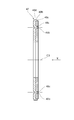
本発明に係るモータの第4の実施形態について説明する。図10に示すように、モータ1Cは小型のブラシレスモータであり、金属製で円形のベース部39を有し、ベース部39の周縁には、円筒状の周壁部39aが形成されている。そして、周壁部39aの内周には、外周が円形である積層コア46(図11参照)が圧入されている。積層コア46の内周に形成されたポール46aには、コイル51が巻回されている。
[Fourth embodiment]
A fourth embodiment of the motor according to the present invention will be described. As shown in FIG. 10, the motor 1 </ b> C is a small brushless motor, and has a
ベース部39の中央には中央孔39cが形成され、中央孔39cには、予圧ばね(図示せず)を挟むようにして上下2段となるラジアル軸受41,42が圧入されている。ラジアル軸受41,42によって支持されたシャフト43は周壁部39aに沿って延在する。シャフト43には、遠心方向に延在する円板状のロータヨーク部44が固定されている。ロータヨーク部44の外縁に沿った円周面には、積層コア46に包囲されるようにして、マグネット45が接着されている。
A
ベース部39上で且つ積層コア46の下方にはホール素子が取り付けられた回路基板が固定されている。コイル51へ通電するとマグネット45が回転し、マグネット45の磁極をホール素子が検出してコイル51への通電が切り替わり、シャフト43が一方向に回転する。
A circuit board to which a Hall element is attached is fixed on the
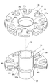
積層コア46は、シャフト43の回転軸線C3方向に沿って積層された複数の単位コア部47によって形成される。単位コア部47は、図12〜図14に示すように、最大磁束密度の異なる二種類の磁性鋼板48,49によって形成される。第1及び第2の磁性鋼板48,49の内周の輪郭は同一形状であり、この内周には、コイル51(図11参照)が巻回される9本のポール部48a,49aが形成されている。
The
第1の磁性鋼板48の外縁の輪郭は円形であり、その外縁から回転軸線C3の方向に突出する円筒状のボス部48bが形成されている。ボス部48bの外周48dは、回転軸線C3の方向に延在する周壁部39aの内周39dに圧入される。一方、第2の磁性鋼板49は、第1の磁性鋼板48よりもわずかに径の小さい円形であり、第2の磁性鋼板49の外周49cは、第1の磁性鋼板48に設けられたボス部48bの内周48eに圧入される。
The outline of the outer edge of the first
また、第1の磁性鋼板48には、回転軸線C3の方向に突出する円柱状の凸部48cが三箇所に形成されている。一方、第2の磁性鋼板49には、凸部48cに圧入される連結孔49bが三個形成されている。第2の磁性鋼板49の連結孔49bには、第1の磁性鋼板48の凸部48cが圧入されて、第2の磁性鋼板49は第1の磁性鋼板48と結合する。第1及び第2の磁性鋼板48,49は内周の輪郭がズレ無く重なり合って一体になり、第1の磁性鋼板48と第2の磁性鋼板49とで単位コア部47が構成される。
Further, the first
単位コア部47の製造にあたっては、図15に示すように、円筒状の積層コア製造用スリーブ52が利用される。積層コア製造用スリーブ52の内径は、円筒状の周壁部39a(図10参照)の内径に対応している。積層コア製造用スリーブ52の内周面には環状の突起部52aが形成されており、最初に緩やかに圧入される単位コア部47は、突起部52aに当接するまで挿入され、その後、他の単位コア部47が順次軽圧入される。このようにして、複数の単位コア部47は心出しが行われながら積層され、その後、絶縁粉体塗装が施されて一体になった後に積層コア製造用スリーブ52から取り外される。積層コア製造用スリーブ52から取り外された積層コア46には、絶縁コーティングが施された後、図11に示すようにコイル51が巻回される。
In manufacturing the
なお、第4の実施形態に係るモータ1Cの変形例として、ベース部39の周壁部39aに、単位コア部47が圧入固定された積層コア製造用スリーブ52を圧入できるようにしてもよい。この場合、積層コア製造用スリーブ52とともに積層コア46を周壁部39a内に固定し、積層コア46がマグネットを包囲するように構成することも可能である。
As a modification of the motor 1 </ b> C according to the fourth embodiment, a laminated
モータ1Cの積層コア46は、複数の単位コア部47の積層によって形成され、単位コア部47は最大磁束密度の二種類の磁性鋼板48,49の組み合わせによって形成される。その結果として、積層コア46の最大磁束密度のバリエーションは広がり、最大磁束密度の選択性が向上する。さらに、熱処理を施す場合、単位コア部47は二種類の磁性鋼板48,49の圧入結合による一体化により、各磁性鋼板48,49に対して個別に熱処理を施す場合に比べて、歪みその他の変形を生じ難い。そして、歪みの少ない単位コア部47が利用される結果として、積層コア46の品質を向上できる。そして、積層コア46の品質向上がモータ1Cの回転精度向上に寄与する。
The
さらに、第1の磁性鋼板48の外縁には、回転軸線C3の方向に突出する円筒状のボス部48bが形成され、第2の磁性鋼板49は、ボス部48b内に圧入されるので、単位コア部47の製作が容易になる。さらに、ベース部39の周壁部39a内に単位コア部47を圧入するに際し、第1の磁性鋼板48と第2の磁性鋼板49との間での心出しが不要になる。従って、複数の単位コア部47を周壁部39a内に圧入する際の精度向上と組立作業性向上とが両立する。
Further, a
本発明は、以上の実施形態に限定されず、一方の磁性鋼板に形成される凸部及び他方の磁性鋼板に形成される連結孔は単数であってもよく、さらに、2または4以上の複数であってもよい。また、単位コア部を構成する複数の磁性鋼板は4枚以上であってもよい。さらに、磁性鋼板の磁気特性としては、最大磁束密度に限定されず、透磁率や周波数特性、鉄損などであってもよく、例えば、特異な周波数特性を持つ軟磁性材料によって形成された磁性鋼板と、低鉄損磁性材料によって形成された磁性鋼板とを組み合わせて単位コア部を形成するようにすることも可能である。 The present invention is not limited to the above-described embodiment, and the number of convex portions formed on one magnetic steel plate and the number of connecting holes formed on the other magnetic steel plate may be single, and two or four or more. It may be. Further, the number of the plurality of magnetic steel plates constituting the unit core portion may be four or more. Furthermore, the magnetic properties of the magnetic steel sheet are not limited to the maximum magnetic flux density, and may be magnetic permeability, frequency characteristics, iron loss, etc. For example, a magnetic steel sheet formed of a soft magnetic material having a unique frequency characteristic. It is also possible to form a unit core portion by combining a magnetic steel plate formed of a low iron loss magnetic material.
また、積層コアは、複数の単位コア部を積層した状態でリベット留め、接着または抵抗溶接によって固定し、その後、粉体塗装を施して製造してもよい。 Further, the laminated core may be manufactured by riveting, adhering or resistance welding in a state in which a plurality of unit core parts are laminated, and then applying powder coating.
1A,1B,1C…モータ、10,30,43…シャフト、13,32,46…積層コア、14,33,51…コイル、17,22,35,47…単位コア部、18,23,36,48…第1の磁性鋼板、18c,23a,36c,48b…ボス部、18d,23b,36b,48c…凸部、18f,23c,36d,48d,49c…外周、48e…内周、19,24,37,49…第2の磁性鋼板、19c,24a,25a…円孔、19d,24b,25b,37b,49b…連結孔、25…第3の磁性鋼板、39a…周壁部、39d…内周、C1,C2,C3…回転軸線。
1A, 1B, 1C ...
Claims (3)
前記積層コアは、磁気特性の異なる二種以上の磁性鋼板のうち、一方の前記磁性鋼板に形成された単数または複数の凸部が他方の前記磁性鋼板に形成された単数または複数の連結孔にそれぞれ圧入されて一体になった単位コア部を、シャフトの回転軸線方向に沿って積層したことを特徴とするモータ。 In a motor in which a coil is wound around a laminated core,
Of the two or more types of magnetic steel plates having different magnetic properties, the laminated core has one or more protrusions formed on one of the magnetic steel plates in one or more connecting holes formed on the other magnetic steel plate. A motor characterized in that unit core portions that are press-fitted and integrated are laminated along the rotational axis direction of the shaft.
一方の前記磁性鋼板には、外縁から前記シャフトの回転軸線方向に突出した筒状のボス部が形成され、前記ボス部の内周には、他方の前記磁性鋼板の外周が圧入され、前記ボス部の外周は前記周壁部の内周に圧入されることを特徴とする請求項1記載のモータ。 A base portion having a cylindrical peripheral wall portion extending in the rotation axis direction of the shaft;
One of the magnetic steel plates is formed with a cylindrical boss portion that protrudes from the outer edge in the direction of the rotation axis of the shaft. The outer periphery of the other magnetic steel plate is press-fitted into the inner periphery of the boss portion, and the boss The motor according to claim 1, wherein an outer periphery of the portion is press-fitted into an inner periphery of the peripheral wall portion.
Priority Applications (1)
| Application Number | Priority Date | Filing Date | Title |
|---|---|---|---|
| JP2006056828A JP2007236148A (en) | 2006-03-02 | 2006-03-02 | Motor |
Applications Claiming Priority (1)
| Application Number | Priority Date | Filing Date | Title |
|---|---|---|---|
| JP2006056828A JP2007236148A (en) | 2006-03-02 | 2006-03-02 | Motor |
Publications (1)
| Publication Number | Publication Date |
|---|---|
| JP2007236148A true JP2007236148A (en) | 2007-09-13 |
Family
ID=38556163
Family Applications (1)
| Application Number | Title | Priority Date | Filing Date |
|---|---|---|---|
| JP2006056828A Pending JP2007236148A (en) | 2006-03-02 | 2006-03-02 | Motor |
Country Status (1)
| Country | Link |
|---|---|
| JP (1) | JP2007236148A (en) |
Cited By (3)
| Publication number | Priority date | Publication date | Assignee | Title |
|---|---|---|---|---|
| JP2013093951A (en) * | 2011-10-25 | 2013-05-16 | Minebea Co Ltd | Motor for disk rotation and disk driving device using the same |
| DE102020114033A1 (en) | 2020-05-26 | 2021-12-02 | Bayerische Motoren Werke Aktiengesellschaft | Laminated core for a rotor with different mechanical strengths, method for manufacturing a laminated core, rotor and electrical machine |
| JP7447845B2 (en) | 2021-02-25 | 2024-03-12 | ニデック株式会社 | Rotor, IPM motor equipped with the same, and method for manufacturing the rotor |
Citations (4)
| Publication number | Priority date | Publication date | Assignee | Title |
|---|---|---|---|---|
| JPS6454744A (en) * | 1987-08-26 | 1989-03-02 | Fujitsu Miyagi Electron Kk | Container for semiconductor device |
| JP2001057747A (en) * | 1999-08-12 | 2001-02-27 | Sankyo Seiki Mfg Co Ltd | Multilayer core of motor and its manufacturing method, and the motor |
| JP2003231206A (en) * | 2002-02-12 | 2003-08-19 | Mitsui High Tec Inc | Heterogeneous material-laminated metal sheet |
| JP2003304654A (en) * | 2002-04-08 | 2003-10-24 | Mitsui High Tec Inc | Stacked iron core |
-
2006
- 2006-03-02 JP JP2006056828A patent/JP2007236148A/en active Pending
Patent Citations (4)
| Publication number | Priority date | Publication date | Assignee | Title |
|---|---|---|---|---|
| JPS6454744A (en) * | 1987-08-26 | 1989-03-02 | Fujitsu Miyagi Electron Kk | Container for semiconductor device |
| JP2001057747A (en) * | 1999-08-12 | 2001-02-27 | Sankyo Seiki Mfg Co Ltd | Multilayer core of motor and its manufacturing method, and the motor |
| JP2003231206A (en) * | 2002-02-12 | 2003-08-19 | Mitsui High Tec Inc | Heterogeneous material-laminated metal sheet |
| JP2003304654A (en) * | 2002-04-08 | 2003-10-24 | Mitsui High Tec Inc | Stacked iron core |
Cited By (3)
| Publication number | Priority date | Publication date | Assignee | Title |
|---|---|---|---|---|
| JP2013093951A (en) * | 2011-10-25 | 2013-05-16 | Minebea Co Ltd | Motor for disk rotation and disk driving device using the same |
| DE102020114033A1 (en) | 2020-05-26 | 2021-12-02 | Bayerische Motoren Werke Aktiengesellschaft | Laminated core for a rotor with different mechanical strengths, method for manufacturing a laminated core, rotor and electrical machine |
| JP7447845B2 (en) | 2021-02-25 | 2024-03-12 | ニデック株式会社 | Rotor, IPM motor equipped with the same, and method for manufacturing the rotor |
Similar Documents
| Publication | Publication Date | Title |
|---|---|---|
| JP5128538B2 (en) | Axial gap type rotating electrical machine | |
| JP6145848B2 (en) | Permanent magnet embedded motor and method for manufacturing the same | |
| JP6429115B2 (en) | motor | |
| JP2001238377A (en) | Rotating electric machine | |
| JP6584331B2 (en) | Single-phase brushless motor and method for manufacturing single-phase brushless motor | |
| JP7266180B2 (en) | Rotor and motor with same | |
| JP2013090368A (en) | Rotor of rotary electric machine | |
| JP2019022301A (en) | motor | |
| JP2007236148A (en) | Motor | |
| JP6210003B2 (en) | Stator core, rotating electric machine, and stator core manufacturing method | |
| JP5277743B2 (en) | Rotating electric machine | |
| JP6824348B2 (en) | Manufacturing method of single-phase brushless motor, single-phase brushless motor, vacuum cleaner equipped with single-phase brushless motor, and manufacturing method of vacuum cleaner | |
| JP5370686B2 (en) | Brushless motor | |
| JP2003244923A (en) | Flat stepping motor | |
| JP2002136091A (en) | Brushless dc motor | |
| JP2010011621A (en) | End plate for rotating electrical machine | |
| US20180138773A1 (en) | Rotor | |
| JP2002051525A (en) | Stepping motor and rotor thereof | |
| JP2015162996A (en) | brushless motor | |
| JP6162567B2 (en) | Inner rotor type motor | |
| JP7325645B2 (en) | Rotating electric machine and manufacturing method of rotating electric machine | |
| JP2006325365A (en) | Stator partially formed of non-magnetic body and brushless motor using same | |
| JP4033332B2 (en) | Stepping motor | |
| JP2024076831A (en) | motor | |
| JP2008136302A (en) | Stepping motor |
Legal Events
| Date | Code | Title | Description |
|---|---|---|---|
| A621 | Written request for application examination |
Free format text: JAPANESE INTERMEDIATE CODE: A621 Effective date: 20090227 |
|
| A131 | Notification of reasons for refusal |
Free format text: JAPANESE INTERMEDIATE CODE: A131 Effective date: 20110621 |
|
| A977 | Report on retrieval |
Free format text: JAPANESE INTERMEDIATE CODE: A971007 Effective date: 20110622 |
|
| A02 | Decision of refusal |
Effective date: 20111108 Free format text: JAPANESE INTERMEDIATE CODE: A02 |