JP2007232402A - Optical gas detector - Google Patents
Optical gas detector Download PDFInfo
- Publication number
- JP2007232402A JP2007232402A JP2006051177A JP2006051177A JP2007232402A JP 2007232402 A JP2007232402 A JP 2007232402A JP 2006051177 A JP2006051177 A JP 2006051177A JP 2006051177 A JP2006051177 A JP 2006051177A JP 2007232402 A JP2007232402 A JP 2007232402A
- Authority
- JP
- Japan
- Prior art keywords
- ultraviolet
- gas
- detection device
- wavelength
- ultraviolet light
- Prior art date
- Legal status (The legal status is an assumption and is not a legal conclusion. Google has not performed a legal analysis and makes no representation as to the accuracy of the status listed.)
- Pending
Links
- 230000003287 optical effect Effects 0.000 title claims abstract description 45
- 238000000825 ultraviolet detection Methods 0.000 claims abstract description 47
- 238000010521 absorption reaction Methods 0.000 claims abstract description 30
- 239000007789 gas Substances 0.000 claims description 82
- 238000001514 detection method Methods 0.000 claims description 59
- 239000010410 layer Substances 0.000 claims description 31
- 239000000853 adhesive Substances 0.000 claims description 14
- 230000001070 adhesive effect Effects 0.000 claims description 14
- 239000011247 coating layer Substances 0.000 claims description 9
- 229910010272 inorganic material Inorganic materials 0.000 claims description 9
- 239000011147 inorganic material Substances 0.000 claims description 9
- 229910052751 metal Inorganic materials 0.000 claims description 9
- 239000002184 metal Substances 0.000 claims description 9
- QVGXLLKOCUKJST-UHFFFAOYSA-N atomic oxygen Chemical compound [O] QVGXLLKOCUKJST-UHFFFAOYSA-N 0.000 claims description 8
- 239000001301 oxygen Substances 0.000 claims description 8
- 229910052760 oxygen Inorganic materials 0.000 claims description 8
- 239000011241 protective layer Substances 0.000 claims description 8
- 230000003746 surface roughness Effects 0.000 claims description 8
- 238000005259 measurement Methods 0.000 claims description 6
- 239000003973 paint Substances 0.000 claims description 6
- 238000002834 transmittance Methods 0.000 claims description 6
- 230000005540 biological transmission Effects 0.000 claims description 5
- UFHFLCQGNIYNRP-UHFFFAOYSA-N Hydrogen Chemical compound [H][H] UFHFLCQGNIYNRP-UHFFFAOYSA-N 0.000 claims description 4
- 239000001257 hydrogen Substances 0.000 claims description 4
- 229910052739 hydrogen Inorganic materials 0.000 claims description 4
- 239000007769 metal material Substances 0.000 claims description 4
- 238000010030 laminating Methods 0.000 claims description 3
- 230000006866 deterioration Effects 0.000 description 8
- 230000035945 sensitivity Effects 0.000 description 7
- 239000011368 organic material Substances 0.000 description 6
- 230000004048 modification Effects 0.000 description 5
- 238000012986 modification Methods 0.000 description 5
- 230000007423 decrease Effects 0.000 description 4
- 239000000463 material Substances 0.000 description 4
- 239000002861 polymer material Substances 0.000 description 3
- 230000005855 radiation Effects 0.000 description 3
- 239000000919 ceramic Substances 0.000 description 2
- 239000003086 colorant Substances 0.000 description 2
- 239000000470 constituent Substances 0.000 description 2
- 230000007774 longterm Effects 0.000 description 2
- QSHDDOUJBYECFT-UHFFFAOYSA-N mercury Chemical compound [Hg] QSHDDOUJBYECFT-UHFFFAOYSA-N 0.000 description 2
- 229910052753 mercury Inorganic materials 0.000 description 2
- 229920005989 resin Polymers 0.000 description 2
- 239000011347 resin Substances 0.000 description 2
- 239000004065 semiconductor Substances 0.000 description 2
- 229910052710 silicon Inorganic materials 0.000 description 2
- 229920003002 synthetic resin Polymers 0.000 description 2
- 239000000057 synthetic resin Substances 0.000 description 2
- YCKRFDGAMUMZLT-UHFFFAOYSA-N Fluorine atom Chemical compound [F] YCKRFDGAMUMZLT-UHFFFAOYSA-N 0.000 description 1
- 229910001218 Gallium arsenide Inorganic materials 0.000 description 1
- 229910004541 SiN Inorganic materials 0.000 description 1
- 229910004298 SiO 2 Inorganic materials 0.000 description 1
- VYPSYNLAJGMNEJ-UHFFFAOYSA-N Silicium dioxide Chemical compound O=[Si]=O VYPSYNLAJGMNEJ-UHFFFAOYSA-N 0.000 description 1
- XUIMIQQOPSSXEZ-UHFFFAOYSA-N Silicon Chemical compound [Si] XUIMIQQOPSSXEZ-UHFFFAOYSA-N 0.000 description 1
- 229910010413 TiO 2 Inorganic materials 0.000 description 1
- 229910052782 aluminium Inorganic materials 0.000 description 1
- 229910052804 chromium Inorganic materials 0.000 description 1
- 150000001875 compounds Chemical class 0.000 description 1
- 229910052802 copper Inorganic materials 0.000 description 1
- 238000010586 diagram Methods 0.000 description 1
- 238000005516 engineering process Methods 0.000 description 1
- 229910052731 fluorine Inorganic materials 0.000 description 1
- 239000011737 fluorine Substances 0.000 description 1
- 229910052732 germanium Inorganic materials 0.000 description 1
- 229910052737 gold Inorganic materials 0.000 description 1
- 238000000034 method Methods 0.000 description 1
- 229910052750 molybdenum Inorganic materials 0.000 description 1
- 229910052759 nickel Inorganic materials 0.000 description 1
- 150000004767 nitrides Chemical class 0.000 description 1
- 238000007747 plating Methods 0.000 description 1
- 229910052697 platinum Inorganic materials 0.000 description 1
- 239000010703 silicon Substances 0.000 description 1
- 229910052814 silicon oxide Inorganic materials 0.000 description 1
- 229910052709 silver Inorganic materials 0.000 description 1
- 238000004544 sputter deposition Methods 0.000 description 1
- 239000000758 substrate Substances 0.000 description 1
- 229910052719 titanium Inorganic materials 0.000 description 1
- 239000012463 white pigment Substances 0.000 description 1
Images


Classifications
-
- G—PHYSICS
- G01—MEASURING; TESTING
- G01N—INVESTIGATING OR ANALYSING MATERIALS BY DETERMINING THEIR CHEMICAL OR PHYSICAL PROPERTIES
- G01N21/00—Investigating or analysing materials by the use of optical means, i.e. using sub-millimetre waves, infrared, visible or ultraviolet light
- G01N21/17—Systems in which incident light is modified in accordance with the properties of the material investigated
- G01N21/25—Colour; Spectral properties, i.e. comparison of effect of material on the light at two or more different wavelengths or wavelength bands
- G01N21/31—Investigating relative effect of material at wavelengths characteristic of specific elements or molecules, e.g. atomic absorption spectrometry
- G01N21/33—Investigating relative effect of material at wavelengths characteristic of specific elements or molecules, e.g. atomic absorption spectrometry using ultraviolet light
-
- G—PHYSICS
- G01—MEASURING; TESTING
- G01J—MEASUREMENT OF INTENSITY, VELOCITY, SPECTRAL CONTENT, POLARISATION, PHASE OR PULSE CHARACTERISTICS OF INFRARED, VISIBLE OR ULTRAVIOLET LIGHT; COLORIMETRY; RADIATION PYROMETRY
- G01J3/00—Spectrometry; Spectrophotometry; Monochromators; Measuring colours
- G01J3/28—Investigating the spectrum
- G01J3/42—Absorption spectrometry; Double beam spectrometry; Flicker spectrometry; Reflection spectrometry
-
- G—PHYSICS
- G01—MEASURING; TESTING
- G01N—INVESTIGATING OR ANALYSING MATERIALS BY DETERMINING THEIR CHEMICAL OR PHYSICAL PROPERTIES
- G01N21/00—Investigating or analysing materials by the use of optical means, i.e. using sub-millimetre waves, infrared, visible or ultraviolet light
- G01N21/17—Systems in which incident light is modified in accordance with the properties of the material investigated
- G01N21/59—Transmissivity
- G01N21/5907—Densitometers
-
- G—PHYSICS
- G01—MEASURING; TESTING
- G01N—INVESTIGATING OR ANALYSING MATERIALS BY DETERMINING THEIR CHEMICAL OR PHYSICAL PROPERTIES
- G01N21/00—Investigating or analysing materials by the use of optical means, i.e. using sub-millimetre waves, infrared, visible or ultraviolet light
- G01N21/01—Arrangements or apparatus for facilitating the optical investigation
- G01N21/03—Cuvette constructions
- G01N21/05—Flow-through cuvettes
Landscapes
- Physics & Mathematics (AREA)
- Spectroscopy & Molecular Physics (AREA)
- General Physics & Mathematics (AREA)
- Health & Medical Sciences (AREA)
- Life Sciences & Earth Sciences (AREA)
- Chemical & Material Sciences (AREA)
- Analytical Chemistry (AREA)
- Biochemistry (AREA)
- General Health & Medical Sciences (AREA)
- Immunology (AREA)
- Pathology (AREA)
- Investigating Or Analysing Materials By Optical Means (AREA)
Abstract
Description
本発明は、光学式ガス検知装置に関するものである。 The present invention relates to an optical gas detection device.
従来、光学式ガス検知装置として、赤外線を用いたNDIR(非分散赤外線)方式のガス検知装置が知られている(例えば特許文献1参照)。この光学式ガス検知装置は、赤外線を放射する赤外線光源と、赤外線を検出する赤外線センサとを含んでいる。 Conventionally, an NDIR (non-dispersed infrared) type gas detector using infrared rays is known as an optical gas detector (see, for example, Patent Document 1). This optical gas detection device includes an infrared light source that emits infrared rays and an infrared sensor that detects infrared rays.
ところで、CO2やNH3等の多原子からなる分子(以下多原子分子と示す)は、原子間の固有振動周波数(言い換えれば振動に起因する吸収帯)が赤外線波長域にあるため、所定波長の赤外線を吸収する特性がある。したがって、上述の光学式ガス検知装置によって検出することが可能である。
これに対し、例えばO2やH2等の単原子からなる分子は、固有振動周波数が紫外線波長域にあるため、特許文献1に示すような光学式ガス検知装置では検出することができない。 On the other hand, for example, a molecule composed of a single atom such as O 2 or H 2 cannot be detected by an optical gas detector as shown in Patent Document 1 because the natural vibration frequency is in the ultraviolet wavelength range.
本発明は上記問題点に鑑み、紫外線波長域に吸収帯のある被測定ガスを検出できる光学式ガス検知装置を提供することを目的とする。 In view of the above problems, an object of the present invention is to provide an optical gas detection device capable of detecting a measurement gas having an absorption band in the ultraviolet wavelength region.
上記目的を達成する為に請求項1に記載の光学式ガス検知装置は、紫外線を放射する紫外線光源と、紫外線を検出する紫外線検出素子とを備え、紫外線光源から紫外線検出素子に到る紫外線の光路上に被測定ガスが導入され、被測定ガスによる紫外線の吸収度合いを紫外線検出素子により検出して、被測定ガスの濃度を測定することを特徴とする。 In order to achieve the above object, an optical gas detection device according to claim 1 includes an ultraviolet light source that emits ultraviolet light and an ultraviolet light detection element that detects ultraviolet light, and the ultraviolet light from the ultraviolet light source to the ultraviolet light detection element. A gas to be measured is introduced into the optical path, and the concentration of the gas to be measured is measured by detecting the degree of ultraviolet absorption by the gas to be measured by an ultraviolet ray detection element.
このように本発明によれば、紫外線波長域(X線との境界〜可視光との境界(400nm))に吸収帯のある被測定ガスを検出することができる。したがって、請求項2に記載のように、固有振動周波数(言い換えれば振動に起因する吸収帯)が紫外線波長域にある、単原子からなるガス分子(例えば等核二原子分子)を検出することができる。具体的には、請求項3に記載のように、酸素及び水素の少なくとも一方を被測定ガスとすることができる。 Thus, according to the present invention, it is possible to detect a gas to be measured having an absorption band in the ultraviolet wavelength region (boundary with X-rays to boundary with visible light (400 nm)). Therefore, as described in claim 2, it is possible to detect a gas molecule composed of a single atom (for example, an equinuclear diatomic molecule) having a natural vibration frequency (in other words, an absorption band caused by vibration) in an ultraviolet wavelength region. it can. Specifically, as described in claim 3, at least one of oxygen and hydrogen can be used as a gas to be measured.
請求項4に記載のように、紫外線光源が、所定波長域を含む紫外線を放射する構成においては、光学式ガス検知装置として、紫外線の光路上に配置され、所定波長の紫外線を選択的に透過する波長選択フィルタを備えることが好ましい。これにより、紫外線検出素子が、被測定ガスにて一部吸収された紫外線を選択的に検出することができる。すなわち、被測定ガスの濃度を測定することができる。なお、紫外線光源が、所定波長の紫外線を放射する構成においては、波長選択フィルタは特に不要である。 According to a fourth aspect of the present invention, in the configuration in which the ultraviolet light source emits ultraviolet rays including a predetermined wavelength region, the optical gas detection device is arranged on the optical path of the ultraviolet rays and selectively transmits the ultraviolet rays having the predetermined wavelength. It is preferable to provide a wavelength selection filter. Thereby, the ultraviolet ray detection element can selectively detect the ultraviolet ray partially absorbed by the gas to be measured. That is, the concentration of the gas to be measured can be measured. In the configuration in which the ultraviolet light source emits ultraviolet light having a predetermined wavelength, the wavelength selection filter is not particularly necessary.
請求項5に記載のように、波長選択フィルタを、紫外線検出素子上に積層し、接着剤を介して固定しても良い。このように集積することで、装置の体格を小型化することができる。なお、有機系材料からなる接着剤の場合、紫外線の影響で劣化しやすい。したがって、請求項6に記載のように、無機系材料からなる接着剤を採用することが好ましい。 As described in claim 5, the wavelength selection filter may be laminated on the ultraviolet detection element and fixed through an adhesive. By accumulating in this way, the size of the apparatus can be reduced. In the case of an adhesive made of an organic material, it is likely to deteriorate due to the influence of ultraviolet rays. Therefore, as described in claim 6, it is preferable to employ an adhesive made of an inorganic material.
波長選択フィルタとしては、例えば請求項7に記載のように、金属膜を多層に積層してなる多層膜フィルタを採用しても良い。多層膜フィルタの場合、金属膜の構成によって、所定波長の紫外線を選択的に透過することができる。 As the wavelength selection filter, for example, as described in claim 7, a multilayer filter formed by laminating metal films in multiple layers may be adopted. In the case of a multilayer filter, ultraviolet rays having a predetermined wavelength can be selectively transmitted depending on the configuration of the metal film.
また、請求項8に記載のように、測定ガスとして、吸収波長の異なる複数のガスを測定対象とする際には、それぞれのガスに応じて、多層膜フィルタと紫外線検出素子を配置すれば良い。このように構成することで、1つの装置として、複数のガスを検出することが可能となる。 In addition, as described in claim 8, when a plurality of gases having different absorption wavelengths are to be measured as measurement gases, a multilayer filter and an ultraviolet detection element may be arranged according to each gas. . With this configuration, a plurality of gases can be detected as one device.
なお、請求項9に記載のように、多層膜フィルタとして、被測定ガスの吸収波長とは異なる波長の紫外線を透過するリファレンス用フィルタを含み、紫外線検出素子として、リファレンス用フィルタを透過した紫外線を検出するリファレンス用検出素子を含むと良い。これにより、温度依存性や紫外線光源の劣化による影響を除去することができる。 In addition, as described in claim 9, the multilayer filter includes a reference filter that transmits ultraviolet light having a wavelength different from the absorption wavelength of the gas to be measured, and the ultraviolet light that has passed through the reference filter as the ultraviolet detection element. A reference detection element to be detected may be included. Thereby, it is possible to remove the influence of temperature dependency and deterioration of the ultraviolet light source.
上述した多層膜フィルタ以外にも、波長選択フィルタとして、例えば請求項10に記載のように、透過波長を調整可能な可変式フィルタを採用しても良い。可変式フィルタの場合、透過波長を任意で調整することができる。したがって、1つの可変式フィルタと紫外線検出素子とで、吸収波長の異なる複数のガスを測定することが可能である。また、リファレンスを不要とすることもできる。このような可変式フィルタとしては、例えばファブリペローフィルタや回折格子を採用することができる。 In addition to the multilayer filter described above, a variable filter capable of adjusting the transmission wavelength may be employed as the wavelength selection filter, as described in claim 10, for example. In the case of a variable filter, the transmission wavelength can be arbitrarily adjusted. Therefore, it is possible to measure a plurality of gases having different absorption wavelengths with one variable filter and an ultraviolet detection element. Moreover, a reference can be made unnecessary. As such a variable filter, for example, a Fabry-Perot filter or a diffraction grating can be employed.
なお、請求項1〜10いずれか1項に記載の光学式ガス検知装置においては、請求項11に記載のように、紫外線光源から紫外線検出素子に到る紫外線の光路を内部空間に含むハウジングを備え、ハウジング内の空間に、被測定ガスが導入される構成を採用しても良い。このように、ハウジング内に、紫外線光源と紫外線検出素子(必要に応じて波長選択フィルタ)を配置し、ハウジング内の空間に導入される被測定ガスを検出する構成が実用的である。 In the optical gas detection device according to any one of claims 1 to 10, as described in claim 11, a housing including an optical path of ultraviolet rays from an ultraviolet light source to an ultraviolet detection element in an internal space. It is also possible to employ a configuration in which the gas to be measured is introduced into the space in the housing. Thus, it is practical to use a configuration in which an ultraviolet light source and an ultraviolet detection element (a wavelength selection filter as required) are arranged in the housing to detect the gas to be measured introduced into the space in the housing.
請求項12に記載のように、ハウジングの内壁面上に、紫外線の反射層を設けることが好ましい。これによって、紫外線によるハウジングの劣化を防ぐことができる。また、紫外線検出素子の検出感度を向上することができる。 According to a twelfth aspect of the present invention, it is preferable to provide an ultraviolet reflecting layer on the inner wall surface of the housing. Thereby, deterioration of the housing due to ultraviolet rays can be prevented. Further, the detection sensitivity of the ultraviolet detection element can be improved.
具体的には、請求項13に記載のように、反射層として白色塗料による塗布層を採用しても良い。紫外線は、白色に対する反射効率が他の色に比べて大きいので、反射層として好適である。特に、有機材料よりも無機材料からなる白色塗料の方が、劣化に対しては好ましい。 Specifically, as described in claim 13, a coating layer of white paint may be adopted as the reflective layer. Ultraviolet light is suitable as a reflective layer because it has a higher reflection efficiency for white than other colors. In particular, a white paint made of an inorganic material is preferable to deterioration than an organic material.
請求項14に記載のように、反射層として金属材料によるコーティング層を採用しても良い。金属表面での反射効率は樹脂やセラミック等に比べると大きいので、反射層として好適である。 As described in claim 14, a coating layer made of a metal material may be adopted as the reflective layer. Since the reflection efficiency on the metal surface is larger than that of resin, ceramic, etc., it is suitable as a reflection layer.
また、請求項15に記載のように、反射層の表面に、無機系材料からなり、反射層よりも紫外線透過率の高い保護層を設けると良い。これにより、反射層(塗布層、コーティング層)が紫外線により劣化し、剥離するのを防ぐことができる。すなわち、反射層をハウジング内壁面上に維持することができる。また、紫外線透過率が高いので、保護層による反射効率の低下を極力抑制することができる。 In addition, as described in claim 15, a protective layer made of an inorganic material and having a higher ultraviolet transmittance than the reflective layer may be provided on the surface of the reflective layer. Thereby, it can prevent that a reflective layer (a coating layer, a coating layer) deteriorates with an ultraviolet-ray, and peels. That is, the reflective layer can be maintained on the inner wall surface of the housing. Moreover, since the ultraviolet-ray transmittance is high, the fall of the reflective efficiency by a protective layer can be suppressed as much as possible.
請求項16に記載のように、ハウジング内壁面の表面粗さを、紫外線検出素子にて検出される紫外線の検出波長の3倍以下に調整すると良い。表面粗さが大きくなるほど反射効率が小さくなる。特に検出波長の3倍を超えると、反射効率が小さくなることが知られている。したがって、本発明の構成を採用することで、紫外線の反射効率を高めることができる。すなわち、紫外線によるハウジングの劣化を防ぎ、紫外線検出素子の検出感度を向上することができる。なお、請求項17に記載のように、ハウジング内壁面の表面粗さを、紫外線検出素子にて検出される紫外線の検出波長以下に調整すると、より紫外線の反射効率を高めることができる。 According to the sixteenth aspect, the surface roughness of the inner wall surface of the housing may be adjusted to be not more than three times the detection wavelength of the ultraviolet ray detected by the ultraviolet ray detection element. The reflection efficiency decreases as the surface roughness increases. In particular, it is known that the reflection efficiency decreases when the detection wavelength exceeds three times. Therefore, by adopting the configuration of the present invention, the reflection efficiency of ultraviolet rays can be increased. That is, deterioration of the housing due to ultraviolet rays can be prevented, and the detection sensitivity of the ultraviolet detection element can be improved. In addition, as described in claim 17, when the surface roughness of the inner wall surface of the housing is adjusted to be equal to or less than the detection wavelength of the ultraviolet ray detected by the ultraviolet ray detection element, the reflection efficiency of the ultraviolet ray can be further increased.
以下、本発明の実施形態を図に基づいて説明する。
(第1実施形態)
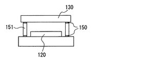
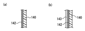
図1は、本発明の第1実施形態に係る光学式ガス検知装置の概略断面図である。図2は、波長選択フィルタと紫外線検出素子との積層構造を示す概略断面図である。図3は、ハウジングの断面構造であり、(a)は反射層を、(b)は反射層と保護層を設けた例を示す図である。
Hereinafter, embodiments of the present invention will be described with reference to the drawings.
(First embodiment)
FIG. 1 is a schematic sectional view of an optical gas detector according to the first embodiment of the present invention. FIG. 2 is a schematic cross-sectional view showing a laminated structure of a wavelength selection filter and an ultraviolet detection element. FIGS. 3A and 3B are sectional views of the housing, in which FIG. 3A is a diagram showing an example in which a reflective layer is provided, and FIG.
本実施形態に係る光学式ガス検知装置は、紫外線波長域に吸収帯のある被測定ガスを検出することを目的として構成されている。図1に示す光学式ガス検知装置100は、紫外線を放射する紫外線光源110、紫外線を検出する紫外線検出素子120、紫外線光源から紫外線検出素子に到る紫外線の光路上に配置された波長選択フィルタ130、及びこれら110〜130を収容するハウジング140とにより構成されている。
The optical gas detection device according to the present embodiment is configured for the purpose of detecting a measurement gas having an absorption band in the ultraviolet wavelength region. An optical
紫外線光源110としては、被測定ガスの吸収帯に応じた波長の紫外線を放射するものであれば採用することができる。本実施形態においては、被測定ガスの吸収帯に合わせて、200nm〜400nm(紫外及び近紫外)の広い放射波長域をもつ光源を採用している。具体的には、エキシマランプや水銀ランプを採用している。
As the ultraviolet
紫外線検出素子120としては、紫外線を検出できるものであれば、光導電型でも良いし、光起電力型でも良い。本実施形態においては、波長選択フィルタ130を透過した紫外線の強度に応じた電気信号を出力する、GaAs等の化合物半導体からなるフォトダイオードを採用している。
The
波長選択フィルタ130は、例えば紫外線光源110として広い放射波長域をもつ光源を採用した場合に、被測定ガスの吸収帯に応じた所定波長(又は所定波長域)の紫外線のみを選択的に透過させて、紫外線検出素子120に受光させるためのものである。本実施形態においては、波長選択フィルタ130として透過波長を任意で調整することのできるファブリペローフィルタを採用している。ファブリペローフィルタは、例えばMo、Si、Geなどで構成された透過膜をギャップ間に挟んで対向させ、ギャップ間隔を任意に変更可能とすることで、ギャップ間で多重反射を起こさせる可変式のフィルタであり、例えばMEMS技術を用いて形成することができる(例えば本出願人が先に出願した特開2005−215323号公報を参照)。このような可変式のフィルタとしては、ファブリペローフィルタ以外にも、回折格子などを採用することができる。
For example, when a light source having a wide radiation wavelength range is adopted as the ultraviolet
また、本実施形態においては、図2に示すように、波長選択フィルタ130を紫外線検出素子120上に積層配置し、接着剤150を介して固定している。このように両者を積層配置する構造を採用すると、装置100の体格を小型化することができる。なお、図2において、符号151は、紫外線検出素子120を構成する基板上に波長選択フィルタ130を離間して支持するための支持部を示している。この支持部151は必須の構成ではなく、波長選択フィルタ130を紫外線検出素子120の受光面に対して直接配置し、接着剤150を介して固定することも可能である。この場合、装置100の体格をより小型化することができる。
Further, in this embodiment, as shown in FIG. 2, the
なお、上述した接着剤150として、有機系材料(高分子材料)からなる接着剤を用いると、有機系材料(高分子材料)が紫外線の影響で劣化するため、長期的な接続信頼性を確保することが困難である。これに対し、本実施形態においては、有機系材料(高分子材料)よりも耐久性を有する無機系材料からなる接着剤(例えばシリコン系接着剤)を、接着剤150として採用している。したがって、長期的な接続信頼性を確保することが可能である。 Note that if an adhesive made of an organic material (polymer material) is used as the above-described adhesive 150, the organic material (polymer material) deteriorates due to the influence of ultraviolet rays, so long-term connection reliability is ensured. Difficult to do. In contrast, in the present embodiment, an adhesive (for example, a silicon-based adhesive) made of an inorganic material that is more durable than an organic material (polymer material) is used as the adhesive 150. Therefore, long-term connection reliability can be ensured.
ハウジング140は、例えば合成樹脂やAl等の金属を構成材料とし、紫外線光源110、紫外線検出素子120、及び波長選択フィルタ130を内部に収容し、紫外線光源110から紫外線検出素子120に到る紫外線の光路を制限するように構成されている。言い換えれば、紫外線光源110から紫外線検出素子120に到る紫外線の光路を内部空間に含むように構成されている。本実施形態においては、筒状部材の両端部(開口端部)を蓋してハウジング140が構成されており、一方の端部(蓋部)に紫外線光源110が配置され、他方の端部(蓋部)に紫外線検出素子120が配置されている。したがって、紫外線光源110から放射された紫外線は、波長選択フィルタ130を介して直接紫外線検出素子120に入射するか、或いは、ハウジング140にて反射された後に、波長選択フィルタ130を介して直接紫外線検出素子120に入射するように構成されている。このように、ハウジング140によって紫外線の光路を制限することで、紫外線検出素子120の検出感度を向上(受光効率を向上)することができる。なお、図1において、符号141は、ハウジング140の筒状部分に設けられた、ハウジング140の外部とハウジング140の内部空間との間で、被測定ガスを流通可能とする窓部141である。
The
また、図3(a)に示すように、本実施形態においては、紫外線検出素子120の検出感度をさらに向上(受光効率を向上)するために、ハウジング140の内壁面に紫外線の反射層142を設けている。これによって、ハウジング140の内壁面における反射効率が向上するので、紫外線検出素子120の検出感度が向上する。また、紫外線によるハウジング140の劣化を防ぐことができる。特にハウジング140が合成樹脂からなる場合には効果的である。
Further, as shown in FIG. 3A, in the present embodiment, in order to further improve the detection sensitivity of the ultraviolet detection element 120 (improve the light receiving efficiency), an
このような反射層142としては、例えば白色塗料による塗布層を採用することができる。白色の紫外線反射効率が他の色の紫外線反射効率に比べて大きいので、反射層142として好適である。特に無機材料からなる白色塗料を用いると、有機材料からなる白色塗料を用いる場合に比べて、反射層142の劣化を防ぐことができる。このような無機材料としては、例えば公知の白色顔料(例えばZnO、TiO2、リトポン)を採用することができる。
As such a
また、反射層142としては、上述の白色塗布層以外にも、例えば金属材料によるコーティング層を採用することができる。金属表面での反射効率は樹脂やセラミック等に比べると大きいので、反射層として好適である。このような金属材料としては、紫外線反射効率の高いAg、Al、Au、Cr、Cu、Ni、Ti、Ptを採用することが好ましく、これらの材料をスパッタ、CVD、メッキ等の方法を用いてハウジング140の内壁面に成膜し、反射層142とすれば良い。
In addition to the white coating layer described above, for example, a coating layer made of a metal material can be employed as the
なお、構成材料自体が紫外線に対する耐久性を有するものであれば、反射層142をそのまま露出させることも可能である。しかしながら、図3(b)に示すように、反射層142の表面に、無機系材料からなり、反射層142よりも紫外線透過率の高い保護層143を設けると良い。これにより、反射層142が紫外線により劣化し、ハウジング140から剥離するのを防ぐことができる。すなわち、反射層142をハウジング140の内壁面上に維持することができるので、剥離による反射効率の低下を防ぐことができる。また、紫外線透過率が高いので、保護層143による反射効率の低下を極力抑制することができる。保護層143の構成材料としては、例えば紫外線透過率の高いMgF2、SiO2、SiN、SiONを採用することができる。なかでもフッ素含有のシリカガラスが好適である。
Note that if the constituent material itself has durability against ultraviolet rays, the
ところで、紫外線(光)反射表面の表面粗さが大きくなるほど紫外線(光)の反射効率が小さくなり、特に検出波長の3倍を超えると反射効率が急激に小さくなることが知られている。そこで、本実施形態においては、ハウジング140の内壁面(その内壁面上に形成された反射層142等を含む)の表面粗さを、紫外線検出素子120にて検出される紫外線の検出波長(換言すれば被測定ガスの吸収波長)の3倍以下(例えば1.2μm以下)となるように調整している。したがって、紫外線の反射効率を高めることができる。すなわち、紫外線によるハウジング140の劣化を防ぎ、紫外線検出素子120の検出感度を向上することができる。なお、ハウジング140の内壁面の表面粗さを、紫外線検出素子120にて検出される紫外線の検出波長以下(例えば0.2μm以下)となるように調整すると、より紫外線の反射効率を高めることができる。
By the way, it is known that as the surface roughness of the ultraviolet (light) reflecting surface increases, the reflection efficiency of ultraviolet (light) decreases, and particularly when the surface wavelength exceeds three times the detection wavelength, the reflection efficiency decreases rapidly. Therefore, in the present embodiment, the surface roughness of the inner wall surface of the housing 140 (including the
このように構成される光学式ガス検知装置100においては、上述したように、波長選択フィルタ130として、透過波長を任意に調整可能な可変式のファブリペローフィルタを採用している。したがって、図1に示すように、1つの波長選択フィルタ130と紫外線検出素子120とで、吸収波長の異なる複数のガスを測定することが可能である。また、被測定ガスの紫外線吸収量の温度依存性や紫外線光源110の劣化による紫外線量(強度)の変化の影響を除去することを目的として、被測定ガスの吸収波長とは異なる波長の紫外線を検出するリファレンスの機能も果たすことができる。すなわち、装置100の体格を小型化することができる。
In the optical
このように本実施形態に係る光学式ガス検知装置100によれば、紫外線波長域に吸収帯のある被測定ガス、例えば固有振動周波数(言い換えれば振動に起因する吸収帯)が紫外線波長域にある単原子分子(例えば等核二原子分子)を検出することができる。このような単原子分子としては、例えば酸素や水素がある。本実施形態においては、酸素を被測定ガスとしている。酸素は固有振動周波数が200〜240nmであるので、300nm程度の波長をリファレンスとし、紫外線検出素子120の、酸素に対応する波長の紫外線検出時の電気信号とリファレンスに対応する波長の紫外線検出時の電気信号とを比較して、酸素のガス濃度を算出するようにしている。なお、被測定ガスとして、酸素と水素を検出することも可能である。
As described above, according to the optical
以上、本発明の好ましい実施形態について説明したが、本発明は上述した実施形態になんら制限されることなく、本発明の主旨を逸脱しない範囲において、種々変形して実施することが可能である。 The preferred embodiments of the present invention have been described above. However, the present invention is not limited to the above-described embodiments, and various modifications can be made without departing from the spirit of the present invention.
本実施形態においては、波長選択フィルタ130を紫外線検出素子120上に積層配置する例を示した。しかしながら、波長選択フィルタ130の配置は上記例に限定されるものではない。紫外線の光路上であれば良い。例えば、紫外線光源110上に積層配置しても良い。
In the present embodiment, an example in which the
また、本実施形態においては、波長選択フィルタ130として、可変式のフィルタ(一例としてファブリペローフィルタ)を採用する例を示した。しかしながら、可変式のフィルタ以外にも、金属膜を多層に積層してなる多層膜フィルタを採用することができる。この多層膜フィルタは、屈折率の異なる金属膜を交互に積層してなる公知のものであり、金属膜の構成によって、所定波長の紫外線を選択的に透過することができる。したがって、吸収波長の異なる複数のガスを測定対象とする際には、例えば図4に示すように、それぞれのガスに応じて波長選択フィルタ130(131,132)と紫外線検出素子120(121,122)を配置すれば良い。また、リファレンスを必要とする場合には、図4に示すように、波長選択フィルタ130として被測定ガスの吸収波長とは異なる波長の紫外線を透過するリファレンス用フィルタ133を、紫外線検出素子120として、リファレンス用フィルタ133を透過した紫外線を検出するリファレンス用検出素子123を配置すれば良い。図4は、変形例を示す断面図である。
In the present embodiment, an example in which a variable filter (a Fabry-Perot filter as an example) is employed as the
また、本実施形態においては、紫外線光源110として、被測定ガスの吸収帯に合わせて、200nm〜400nm(紫外及び近紫外)の広い放射波長域をもつ光源(例えばエキシマランプや水銀ランプ)を採用する例を示した。しかしながら、紫外線光源110は上記例に限定されるものではない。被測定ガスの吸収帯に応じた波長の紫外線を放射するものであれば採用することができる。具体的には、LED(例えば3族窒化物半導体等による)やレーザ(ArFレーザ、F2レーザ、LD等)を採用することができる。これらは、放射波長域が狭く、指向性も高いので、紫外線検出素子120の検出感度を向上することができる。また、図5に示すように、波長選択フィルタ130を不要とすることも可能であり、これにより装置100の体格を小型化することができる。さらにLEDやLDは小型の発光素子であるので、これによっても装置100の体格を小型化することができる。なお、吸収波長の異なる複数のガスを被測定ガスとする場合には、それぞれの吸収波長に対応する波長の紫外線を放射する紫外線光源110と、紫外線光源110に対応する紫外線検出素子120を配置すれば良い。また、リファレンスを必要とする場合には、被測定ガスの吸収波長とは異なる波長の紫外線を放射するリファレンス用の紫外線光源110と、リファレンス用の紫外線光源110に対応するリファレンス用の紫外線検出素子120を配置すれば良い。図5は、変形例を示す断面図である。
In the present embodiment, a light source (for example, an excimer lamp or a mercury lamp) having a wide radiation wavelength range of 200 nm to 400 nm (ultraviolet and near ultraviolet) is adopted as the ultraviolet
また、本実施形態においては、筒状部材の両端部(開口端部)を蓋してハウジング140が構成されており、一方の端部(蓋部)に紫外線光源110が配置され、他方の端部(蓋部)に紫外線検出素子120が配置される例を示した。しかしながら、ハウジング140の構成、ハウジング140における紫外線光源110と紫外線検出素子120の配置は上記例に限定されるものではない。例えば、紫外線光源110から放射された紫外線が、反射鏡を介して、紫外線検出素子120に到達するように、紫外線光源110と紫外線検出素子120がハウジング140の同一端部に配置されても良い。
In the present embodiment, the
また、本実施形態においては、ハウジング140内に、紫外線光源110、紫外線検出素子120、及び波長選択フィルタ130を配置する例を示した。しかしながら、ハウジング140を含まない構成としても良い。
In the present embodiment, an example in which the
100・・・光学式ガス検知装置
110・・・紫外線光源
120・・・紫外線検出素子
122・・・リファレンス用検出素子
130・・・波長選択フィルタ
133・・・リファレンス用フィルタ
140・・・ハウジング
142・・・反射層
143・・・保護層
150・・・接着剤
DESCRIPTION OF
Claims (17)
紫外線を検出する紫外線検出素子とを備え、
前記紫外線光源から前記紫外線検出素子に到る紫外線の光路上に被測定ガスが導入され、
前記被測定ガスによる紫外線の吸収度合いを前記紫外線検出素子により検出して、前記被測定ガスの濃度を測定することを特徴とする光学式ガス検知装置。 An ultraviolet light source that emits ultraviolet light;
An ultraviolet detection element for detecting ultraviolet rays,
A gas to be measured is introduced on an optical path of ultraviolet rays from the ultraviolet light source to the ultraviolet detection element,
An optical gas detection apparatus, wherein the concentration of the gas to be measured is measured by detecting the degree of absorption of ultraviolet light by the gas to be measured by the ultraviolet light detecting element.
前記紫外線の光路上に配置され、所定波長の紫外線を選択的に透過する波長選択フィルタを備えることを特徴とする請求項1〜3いずれか1項に記載の光学式ガス検知装置。 The ultraviolet light source emits ultraviolet light including a predetermined wavelength range,
The optical gas detection device according to claim 1, further comprising a wavelength selection filter that is disposed on the optical path of the ultraviolet rays and selectively transmits ultraviolet rays having a predetermined wavelength.
それぞれの前記ガスに応じて、前記多層膜フィルタと前記紫外線検出素子が配置されていることを特徴とする請求項7に記載の光学式ガス検知装置。 As the measurement gas, a plurality of gases having different absorption wavelengths are to be measured,
The optical gas detection device according to claim 7, wherein the multilayer filter and the ultraviolet detection element are arranged according to each gas.
前記紫外線検出素子として、前記リファレンス用フィルタを透過した紫外線を検出するリファレンス用検出素子を含むことを特徴とする請求項7又は請求項8に記載の光学式ガス検知装置。 As the multilayer filter, including a reference filter that transmits ultraviolet light having a wavelength different from the absorption wavelength of the gas to be measured,
The optical gas detection device according to claim 7, wherein the ultraviolet detection element includes a reference detection element that detects ultraviolet light transmitted through the reference filter.
前記ハウジング内の空間に、前記被測定ガスが導入されることを特徴とする請求項1〜10いずれか1項に記載の光学式ガス検知装置。 A housing including an ultraviolet light path from the ultraviolet light source to the ultraviolet detection element in an internal space;
The optical gas detection device according to claim 1, wherein the gas to be measured is introduced into a space in the housing.
Priority Applications (5)
| Application Number | Priority Date | Filing Date | Title |
|---|---|---|---|
| JP2006051177A JP2007232402A (en) | 2006-02-27 | 2006-02-27 | Optical gas detector |
| US11/640,873 US20070200067A1 (en) | 2006-02-27 | 2006-12-19 | Optical gas-detecting device |
| KR1020070013317A KR100866589B1 (en) | 2006-02-27 | 2007-02-08 | Optical gas-detecting device |
| CNA2007100051944A CN101029865A (en) | 2006-02-27 | 2007-02-15 | Optical gas-detecting device |
| DE102007008932A DE102007008932A1 (en) | 2006-02-27 | 2007-02-23 | Optical gas detection device |
Applications Claiming Priority (1)
| Application Number | Priority Date | Filing Date | Title |
|---|---|---|---|
| JP2006051177A JP2007232402A (en) | 2006-02-27 | 2006-02-27 | Optical gas detector |
Publications (1)
| Publication Number | Publication Date |
|---|---|
| JP2007232402A true JP2007232402A (en) | 2007-09-13 |
Family
ID=38329480
Family Applications (1)
| Application Number | Title | Priority Date | Filing Date |
|---|---|---|---|
| JP2006051177A Pending JP2007232402A (en) | 2006-02-27 | 2006-02-27 | Optical gas detector |
Country Status (5)
| Country | Link |
|---|---|
| US (1) | US20070200067A1 (en) |
| JP (1) | JP2007232402A (en) |
| KR (1) | KR100866589B1 (en) |
| CN (1) | CN101029865A (en) |
| DE (1) | DE102007008932A1 (en) |
Cited By (2)
| Publication number | Priority date | Publication date | Assignee | Title |
|---|---|---|---|---|
| JP2011117884A (en) * | 2009-12-07 | 2011-06-16 | Hioki Ee Corp | Spectrophotometer |
| WO2013047799A1 (en) * | 2011-09-30 | 2013-04-04 | 国立大学法人豊橋技術科学大学 | Physical/chemical sensor, physical/chemical phenomenon sensing device, and method for manufacturing same |
Families Citing this family (11)
| Publication number | Priority date | Publication date | Assignee | Title |
|---|---|---|---|---|
| CN102235969B (en) * | 2010-04-21 | 2013-05-01 | 中国科学院微电子研究所 | Multi-channel filter array MEMS spectral gas sensor |
| US8003945B1 (en) * | 2010-08-25 | 2011-08-23 | Jacob Y Wong | Intrinsically safe NDIR gas sensor in a can |
| EP2857811B1 (en) * | 2013-10-02 | 2015-09-23 | Sick Ag | Spectrometer for gas analysis |
| CN106442955B (en) * | 2016-11-09 | 2023-05-16 | 苏州一呼医疗科技有限公司 | Reflective optical detection device of intelligent expiration molecular diagnosis system |
| CN106596444A (en) * | 2016-12-08 | 2017-04-26 | 哈尔滨工业大学 | Oxygen concentration measuring system based on ultraviolet broadband absorption spectrum and measuring method |
| IT201700035910A1 (en) * | 2017-03-31 | 2018-10-01 | St Microelectronics Srl | OPTOELECTRONIC DEVICE FOR THE SELECTIVE DETECTION OF VOLATILE ORGANIC COMPOUNDS AND ITS MANUFACTURING PROCEDURE |
| KR102326927B1 (en) * | 2017-04-28 | 2021-11-16 | 쑤저우 레킨 세미컨덕터 컴퍼니 리미티드 | Light emiting device and gas sensor using the same |
| WO2019238915A1 (en) * | 2018-06-14 | 2019-12-19 | Ams International Ag | Integrated sensor modules for detection of chemical substances |
| KR102059532B1 (en) | 2019-06-20 | 2019-12-27 | 주식회사 넷 | Monitoring system of idling vehicle |
| WO2023153561A1 (en) * | 2022-02-09 | 2023-08-17 | 한양대학교 에리카산학협력단 | Complex gas sensor, method for manufacturing same, and method for controlling complex gas sensor |
| KR102623012B1 (en) * | 2023-10-17 | 2024-01-10 | 한국표준과학연구원 | Multi-channel gas detection device and manufacturing method thereof |
Citations (6)
| Publication number | Priority date | Publication date | Assignee | Title |
|---|---|---|---|---|
| JPS544185A (en) * | 1977-06-10 | 1979-01-12 | Hewlett Packard Yokogawa | Oxygen concentration measuring device |
| JPS6214769B2 (en) * | 1975-05-16 | 1987-04-03 | Erubin Jitsuku Oputeiku Erekutoroniku | |
| JPH08313438A (en) * | 1995-05-20 | 1996-11-29 | Horiba Ltd | Fluid modulation type ultraviolet gas analyzer |
| JPH11230899A (en) * | 1997-11-14 | 1999-08-27 | Ethicon Inc | Apparatus and method for measuring concentration of hydrogen peroxide vapor, etc. |
| JP2004309296A (en) * | 2003-04-07 | 2004-11-04 | Horiba Ltd | Light absorption type analyzer |
| JP2006053078A (en) * | 2004-08-12 | 2006-02-23 | Nippon Telegr & Teleph Corp <Ntt> | Optical type detection microcell, and manufacturing method therefor |
Family Cites Families (11)
| Publication number | Priority date | Publication date | Assignee | Title |
|---|---|---|---|---|
| US3826920A (en) * | 1973-04-12 | 1974-07-30 | Massachusetts Inst Technology | Fluorescent gas analyzer with calibration system |
| US4069441A (en) * | 1974-05-06 | 1978-01-17 | U.S. Philips Corporation | Electric gas discharge lamp having two superposed luminescent layers |
| US4192996A (en) * | 1978-07-12 | 1980-03-11 | Hewlett-Packard Company | Measurement of oxygen by differential absorption of UV radiation |
| US4591721A (en) * | 1984-10-10 | 1986-05-27 | Andors Analyzers Incorporated | Oxygen analysis employing absorption spectroscopy |
| JPS62153734A (en) * | 1985-12-27 | 1987-07-08 | Hitachi Ltd | Measuring method and apparatus therefor |
| JPH08313439A (en) * | 1995-05-20 | 1996-11-29 | Horiba Ltd | Ultraviolet gas analyzer |
| US5652431A (en) * | 1995-10-06 | 1997-07-29 | The United States Of America As Represented By The Secretary Of The Navy | In-situ monitoring and feedback control of metalorganic precursor delivery |
| US6075609A (en) * | 1998-03-26 | 2000-06-13 | Antek Industrial Instruments, Inc. | Apparatus and methods for improving fluorescence detectors |
| US6556301B2 (en) * | 1998-11-26 | 2003-04-29 | Infrared Integrated Systems Ltd. | Versatile filter based spectrophotometer |
| EP1302234A1 (en) * | 2001-09-27 | 2003-04-16 | Hoya- Schott Corporation | Light-transmittable linear photocatalytic filter material, filter to which the material is applied, and process for production thereof |
| EP1605284B1 (en) * | 2003-03-19 | 2012-12-26 | Mitsubishi Denki Kabushiki Kaisha | Wavelength filter and wavelength monitor device |
-
2006
- 2006-02-27 JP JP2006051177A patent/JP2007232402A/en active Pending
- 2006-12-19 US US11/640,873 patent/US20070200067A1/en not_active Abandoned
-
2007
- 2007-02-08 KR KR1020070013317A patent/KR100866589B1/en not_active IP Right Cessation
- 2007-02-15 CN CNA2007100051944A patent/CN101029865A/en active Pending
- 2007-02-23 DE DE102007008932A patent/DE102007008932A1/en not_active Ceased
Patent Citations (6)
| Publication number | Priority date | Publication date | Assignee | Title |
|---|---|---|---|---|
| JPS6214769B2 (en) * | 1975-05-16 | 1987-04-03 | Erubin Jitsuku Oputeiku Erekutoroniku | |
| JPS544185A (en) * | 1977-06-10 | 1979-01-12 | Hewlett Packard Yokogawa | Oxygen concentration measuring device |
| JPH08313438A (en) * | 1995-05-20 | 1996-11-29 | Horiba Ltd | Fluid modulation type ultraviolet gas analyzer |
| JPH11230899A (en) * | 1997-11-14 | 1999-08-27 | Ethicon Inc | Apparatus and method for measuring concentration of hydrogen peroxide vapor, etc. |
| JP2004309296A (en) * | 2003-04-07 | 2004-11-04 | Horiba Ltd | Light absorption type analyzer |
| JP2006053078A (en) * | 2004-08-12 | 2006-02-23 | Nippon Telegr & Teleph Corp <Ntt> | Optical type detection microcell, and manufacturing method therefor |
Cited By (2)
| Publication number | Priority date | Publication date | Assignee | Title |
|---|---|---|---|---|
| JP2011117884A (en) * | 2009-12-07 | 2011-06-16 | Hioki Ee Corp | Spectrophotometer |
| WO2013047799A1 (en) * | 2011-09-30 | 2013-04-04 | 国立大学法人豊橋技術科学大学 | Physical/chemical sensor, physical/chemical phenomenon sensing device, and method for manufacturing same |
Also Published As
| Publication number | Publication date |
|---|---|
| DE102007008932A1 (en) | 2007-09-06 |
| KR20070089052A (en) | 2007-08-30 |
| KR100866589B1 (en) | 2008-11-03 |
| US20070200067A1 (en) | 2007-08-30 |
| CN101029865A (en) | 2007-09-05 |
Similar Documents
| Publication | Publication Date | Title |
|---|---|---|
| JP2007232402A (en) | Optical gas detector | |
| CA2787221C (en) | Gas sensor with radiation guide | |
| US20100192669A1 (en) | Photo acoustic sample detector with light guide | |
| FR2761779A1 (en) | INFRARED ABSORPTION MEASURING DEVICE | |
| US9791366B2 (en) | Gas detector, gas detection method and optical component | |
| JP2007201475A (en) | Narrow band transmission filter for euv radiation | |
| JP7445234B2 (en) | Infrared absorber and gas sensor with infrared absorber | |
| US7715010B2 (en) | Non-dispersive electromagnetic radiation detector | |
| JP2007205920A (en) | Multiple reflection type cell, and infrared type gas detector | |
| CN109283136B (en) | Optical cavity with wide range | |
| JP2014142319A (en) | Infrared application device | |
| JP2005337879A (en) | Gas sensor | |
| JP5932294B2 (en) | Passive optical gaseous emission sensor | |
| JP2006275641A (en) | Spectroscopic gas sensor | |
| JP7240666B2 (en) | Gas sensor with infrared absorber and infrared absorber | |
| JP7228209B2 (en) | Concentration measurement method | |
| US20240295493A1 (en) | Optical physical quantity measuring apparatus | |
| JP5498399B2 (en) | Color detector | |
| JP2011123023A (en) | Photosensor | |
| US11119037B2 (en) | Small form factor spectrally selective absorber with high acceptance angle for use in gas detection | |
| JP5483163B2 (en) | Laser gas analyzer | |
| JP2009180517A (en) | Infrared detection type gas analyzer | |
| JP2023109050A (en) | Optical physical quantity measuring device | |
| JP2022102310A (en) | Infrared absorber, and gas sensor including infrared absorber | |
| Daly et al. | MEMS-based sensor system for environmental monitoring |
Legal Events
| Date | Code | Title | Description |
|---|---|---|---|
| A621 | Written request for application examination |
Free format text: JAPANESE INTERMEDIATE CODE: A621 Effective date: 20080229 |
|
| A131 | Notification of reasons for refusal |
Free format text: JAPANESE INTERMEDIATE CODE: A131 Effective date: 20090428 |
|
| A521 | Written amendment |
Free format text: JAPANESE INTERMEDIATE CODE: A523 Effective date: 20090608 |
|
| A131 | Notification of reasons for refusal |
Free format text: JAPANESE INTERMEDIATE CODE: A131 Effective date: 20090908 |
|
| A521 | Written amendment |
Free format text: JAPANESE INTERMEDIATE CODE: A523 Effective date: 20091103 |
|
| A131 | Notification of reasons for refusal |
Free format text: JAPANESE INTERMEDIATE CODE: A131 Effective date: 20100119 |
|
| A02 | Decision of refusal |
Free format text: JAPANESE INTERMEDIATE CODE: A02 Effective date: 20100525 |