JP2007217954A - Damping device with viscoelastic element, proof-stress wall with damping device which is provided with device, and execution method of stress wall - Google Patents
Damping device with viscoelastic element, proof-stress wall with damping device which is provided with device, and execution method of stress wall Download PDFInfo
- Publication number
- JP2007217954A JP2007217954A JP2006039619A JP2006039619A JP2007217954A JP 2007217954 A JP2007217954 A JP 2007217954A JP 2006039619 A JP2006039619 A JP 2006039619A JP 2006039619 A JP2006039619 A JP 2006039619A JP 2007217954 A JP2007217954 A JP 2007217954A
- Authority
- JP
- Japan
- Prior art keywords
- viscoelastic body
- damping device
- bearing wall
- vibration damping
- cover plate
- Prior art date
- Legal status (The legal status is an assumption and is not a legal conclusion. Google has not performed a legal analysis and makes no representation as to the accuracy of the status listed.)
- Granted
Links
Images


Abstract
Description
本発明は、スチールハウス等の枠組み壁工法による建築物に用いられる粘弾性体付き制振装置およびその装置を備えた制振装置付き耐力壁並びにその耐力壁の施工法に関する。 The present invention relates to a vibration damping device with a viscoelastic body used in a building by a frame wall construction method such as a steel house, a bearing wall with a vibration damping device including the device, and a method of constructing the bearing wall.
従来、粘弾性体を部材間に介在させて減衰効果を発揮するようにした制振装置が知られている(例えば、特許文献1参照)。 Conventionally, a vibration damping device in which a viscoelastic body is interposed between members to exhibit a damping effect is known (see, for example, Patent Document 1).
前記の制振装置における部材間に介在されて使用される粘弾性体としては、シート状の粘弾性体を圧着して使うものと、流動状の粘弾性材体を封入して使用するものとがある。 As the viscoelastic body used by being interposed between the members in the vibration damping device, a sheet-like viscoelastic body is used by pressure bonding, and a fluid viscoelastic material body is enclosed and used. There is.
前者のシート状の場合は、部材間に介在させた状態で所定時間圧力をかけて、粘弾性体の物性を利用して自己接着するようにしている。後者の流動状の場合は、所定の空間をマスキングして充填し、固化するまで所定の形状を維持する必要がある。 In the case of the former sheet shape, pressure is applied for a predetermined time in a state of being interposed between members, and self-adhesion is performed using physical properties of the viscoelastic body. In the latter fluid state, it is necessary to mask and fill a predetermined space and maintain the predetermined shape until solidified.
前記のシート状および流動状の粘弾性体のいずれの場合も、また、現場施工するには長時間を必要とすると共に設備も必要になり、現実的に現場施工は非常に困難である。 In both cases of the above-mentioned sheet-like and fluid viscoelastic bodies, on-site construction requires a long time and requires equipment, so that on-site construction is actually very difficult.
また、(1)粘弾性体を使用した制振技術として従来、柱および間柱とを耐火ボードおよび木ねじにより接合すると共に、柱および間柱と耐火ボードのなす接合面に粘弾性体を介在させて接合する制振建物も知られている(例えば、特許文献1参照)。 In addition, (1) as a vibration damping technique using a viscoelastic body, conventionally, a column and an inter-column are joined by a fire-resistant board and wood screws, and a visco-elastic body is interposed on a joining surface formed by the column, the inter-column and the fire-resistant board. A vibration-damping building is also known (see, for example, Patent Document 1).
前記の場合は、(1)粘弾性体の自己接着を利用して固着させるためには、柱および間柱と耐火ボードとのなす接合面に粘弾性体を介在させた状態で、現場で粘弾性体を長時間圧着する必要があるが、これは現実的には不可能であるという問題がある。また、柱および間柱と耐火ボードとのなす接合面に粘弾性体を介在させた状態で、これらを木ねじにより固定するため、木ねじ周辺に弛みが生じないと粘弾性体がせん断変形できなくなることから、木ねじ周辺に弛みが生じない初期において減衰効果を発揮させることができないという問題がある。 In the above case, (1) In order to fix the self-adhesive of the viscoelastic body, the viscoelastic body is interposed in the state where the viscoelastic body is interposed between the column and the joining surface formed by the inter-column and the fireproof board. Although it is necessary to crimp the body for a long time, there is a problem that this is practically impossible. In addition, the viscoelastic body cannot be shear-deformed unless slack occurs around the wood screw because the viscoelastic body is interposed in the joint surface between the pillar and inter-column and the refractory board. There is a problem that the damping effect cannot be exhibited in the initial stage where no slack occurs around the wood screw.
また、(2)一方の外装パネルと他方の外装パネルの突出プレートとの間に粘弾性体を設置するようにした制振構造も知られている(例えば、特許文献2参照)。 Further, (2) a vibration damping structure in which a viscoelastic body is installed between one exterior panel and the protruding plate of the other exterior panel is also known (see, for example, Patent Document 2).
前記(2)の技術の場合は、粘弾性体を貼り付けた外装パネルと、他方の外装パネルにおける突出プレートを、現場で所定時間圧着する必要があるが、このようにすることは、現実的には現場施工では、不可能であるという問題がある。 In the case of the technique (2), it is necessary to press-bond the exterior panel on which the viscoelastic body is pasted and the protruding plate on the other exterior panel for a predetermined time on site. However, there is a problem that is impossible in the field construction.
また、横方向に隣り合う壁パネル同士の壁が重なる壁厚方向の中間部に、粘弾性体を介在設置する構造であるために、壁パネルの形状が複雑になると共に接合部の構造が複雑になり、壁パネルの製作コストが高くなるという問題がある。 In addition, since the viscoelastic body is interposed in the middle of the wall thickness direction where the walls of the wall panels adjacent in the horizontal direction overlap, the shape of the wall panel is complicated and the structure of the joint is complicated There is a problem that the manufacturing cost of the wall panel becomes high.
また、外装パネルに粘弾性体を設置するため、外気温および輻射熱等により粘弾性体は大きく温度が変化する影響を受け、例えば、40度付近の高温になると粘弾性体による減衰効果が半減するなど、著しく温度依存性のあるアクリル系粘弾性体などの粘弾性体では、粘弾性体のせん断変形等による減衰効果を十分に発揮させることができないという問題がある。 In addition, since the viscoelastic body is installed in the exterior panel, the viscoelastic body is greatly affected by the outside air temperature and radiant heat, and the damping effect of the viscoelastic body is halved at a high temperature around 40 degrees, for example. For example, viscoelastic bodies such as acrylic viscoelastic bodies that are remarkably temperature-dependent have a problem that a damping effect due to shear deformation of the viscoelastic bodies cannot be sufficiently exhibited.
従って、前記のように温度により減衰効果が低下する温度依存性のある粘弾性体では、温度が高温にならないように、(a)外壁材の内側で通気し、かつ外壁材から離れた位置に配置して使用し、極力、高温にならないようにするか、(b)著しい温度変化のない室内側に配置する等の手段が必要になる。
しかし、前記(a)(b)のようにするにしても、さらに、(A)現場施工性がよく、(B)壁厚方向の厚さが薄く、(C)壁パネルの構造が複雑でなく、(D)壁パネルを含めて、安価であること等が必要になり、これらを満足することが望まれる。 However, (A) (b) is also good, (A) On-site workability is good, (B) The thickness in the wall thickness direction is thin, and (C) The structure of the wall panel is complicated. (D) It is necessary to be inexpensive, including wall panels, and it is desirable to satisfy these requirements.
本発明者は、前記の課題を有利に解決するために、種々研究した結果、耐力壁パネルの面材に対して粘弾性体を直接固着するよりも、粘弾性体を別個にユニット化した粘弾性体付き制振装置として、その粘弾性体付き制振装置をドリルねじ等の固着具により壁パネルの面状部材等に固定するようにすることにより、前記(A)の現場施工性の課題をクリアできること。 As a result of various studies in order to advantageously solve the above problems, the present inventor has found that the viscoelastic body is separately unitized rather than directly fixed to the face material of the load bearing wall panel. As the vibration damping device with an elastic body, by fixing the vibration damping device with a viscoelastic body to a planar member or the like of a wall panel by a fixing tool such as a drill screw, the problem of on-site workability of (A) above Can be cleared.
また、隣り合う耐力壁における一方の壁体前面側と、他方の壁体の後面側との間に介在させないで、隣り合う耐力壁パネルにおける前面側の面状部材同士に固定するか、後面側の面状部材同士に固定できる構造にすることにより、耐力壁パネルの単純化が図れ前記(A)の現場施工性の向上により、前記(C)の課題に寄与できること。 Moreover, it is fixed between the planar members on the front side of the adjacent load-bearing wall panels without being interposed between the front side of one wall body in the adjacent load-bearing wall and the rear side of the other wall body, or the rear side. By making it a structure that can be fixed between the planar members, the load-bearing wall panel can be simplified, and the improvement in the field workability of (A) can contribute to the problem of (C).
また、粘弾性体を配置する場合、屋外側の通気胴縁構造あるいは室内側に配置する構造とすることにより、高温領域にならない位置に粘弾性体を配置して、粘弾性体の温度依存性の問題をクリアできること。 In addition, when placing a viscoelastic body, it is possible to place the viscoelastic body at a position that does not become a high temperature region by adopting an outdoor vent structure or indoor structure. Can clear the problem.
また、粘弾性体をユニット化する場合、粘弾性体付き制振装置における各取付部を平行面にし、ほぼ同面上にすることにより、取付部までを含めた粘弾性体付き制振装置の厚さ寸法を小型にできること、また、現場での取付けあるいは工場での取付けが容易になり、取付けの自由度が向上すること。
本発明者は、これらを知見して本発明を完成させた。
In addition, when unitizing viscoelastic bodies, each mounting part in the vibration damping device with viscoelastic body is made parallel and substantially on the same surface, so that the vibration damping device with viscoelastic body including the mounting part is included. Thickness can be reduced, and installation at the site or factory becomes easy and the degree of freedom of installation is improved.
The present inventor has found these facts and completed the present invention.
本発明は、現場での施工性がよい粘弾性体付き制振装置およびその装置を備えた制振装置付き耐力壁並びにその耐力壁の施工法を提供することを主目的とする。 The main object of the present invention is to provide a vibration damping device with a viscoelastic body having good workability on site, a load bearing wall with a vibration damping device including the device, and a method of constructing the load bearing wall.
第1発明の制振装置付き耐力壁では、枠組み壁工法による建物の耐力壁に使用される制振装置付き耐力壁であって、前記耐力壁における隣り合う一方の面状部材および他方の面状部材に、一側部および他側部にそれぞれほぼ同面上に配置された取付け部を有し、かつユニット化された粘弾性体付き制振装置が前記取付け部で固定されていることを特徴とする。 The bearing wall with a damping device according to the first aspect of the present invention is a bearing wall with a damping device used for a bearing wall of a building by a frame wall construction method, wherein one adjacent planar member and the other planar shape of the bearing wall. The member has mounting portions arranged on substantially the same surface on each of the one side portion and the other side portion, and a unitized vibration damping device with a viscoelastic body is fixed by the mounting portion. And
第2発明では、第1発明の制振装置付き耐力壁において、粘弾性体付き制振装置が、耐力壁における屋外側の面状部材、もしくは耐力壁における屋内側の面状部材に固定されていることを特徴とする。 In the second invention, in the bearing wall with the damping device of the first invention, the damping device with the viscoelastic body is fixed to the outdoor-side planar member in the bearing wall or the indoor-side planar member in the bearing wall. It is characterized by being.
第3発明では、第1発明の制振装置付き耐力壁において、粘弾性体付き制振装置が、耐力壁における屋外側の各面状部材表面に固定され、かつ前記粘弾性体付き制振装置は、耐力壁に固定される通気胴縁と、前記耐力壁における縦枠材の間に挟まれる部分に配置され、かつ前記粘弾性体付き制振装置は、前記縦胴縁の接合位置において切り欠き部を有し、かつ粘弾性体付き制振装置における粘弾性体は前記切り欠き部の位置に設けられることなく分割され、さらに前記縦胴縁は前記切り欠き部の位置で耐力壁に固着具により固定されていることを特徴とする。 According to a third aspect of the present invention, in the load-bearing wall with a vibration damping device according to the first invention, the vibration damping device with a viscoelastic body is fixed to the surface of each planar member on the outdoor side of the load bearing wall, and the vibration damping device with the viscoelastic body Is disposed at a portion sandwiched between the ventilation drum edge fixed to the load bearing wall and the vertical frame member of the load bearing wall, and the vibration damping device with a viscoelastic body is cut at the joining position of the vertical drum edge. The viscoelastic body in the vibration damping device with a viscoelastic body having a notch is divided without being provided at the position of the notch, and the vertical trunk edge is fixed to the bearing wall at the position of the notch It is fixed by a tool.
第4発明では、第1〜第3発明のいずれかの制振装置付き耐力壁において、両端部に切り欠きを有する粘弾性体付き制振装置の短尺ユニットが直列に配置されて長尺の粘弾性体付き制振装置が構成されていることを特徴とする。 In the fourth invention, in the bearing wall with a vibration damping device according to any one of the first to third inventions, the short unit of the vibration damping device with a viscoelastic body having notches at both ends is arranged in series to form a long viscous wall. A vibration damping device with an elastic body is configured.
第5発明では、第1発明〜第4発明のいずれかの制振装置付き耐力壁において、工場において製作された粘弾性体付き制振装置とされ、その粘弾性体付き制振装置が、施工現場で隣り合う面状部材同士の接合部に取付けられた耐力壁とされていることを特徴とする。 According to a fifth invention, in the bearing wall with a vibration damping device according to any one of the first to fourth inventions, the vibration damping device with a viscoelastic body manufactured in a factory is provided. It is characterized by being a load bearing wall attached to the joint between adjacent planar members at the site.
第6発明の制振装置付き耐力壁では、外張り断熱構造における耐力壁が、第1発明〜第5発明のいずれかの制振装置付き耐力壁とされていることを特徴とする。ここで、外張り断熱構造における耐力壁とは、図5の外側部分にあるような制振装置付き耐力壁23のような構造を持つものをいう。
The bearing wall with the vibration damping device according to the sixth aspect of the invention is characterized in that the bearing wall in the outer heat insulating structure is the bearing wall with the vibration damping device according to any one of the first to fifth inventions. Here, the load-bearing wall in the outer heat insulating structure refers to a load-bearing wall having a structure like the load-bearing
第7発明では、第1発明〜第6発明のいずれかの制振装置付き耐力壁において、面状部材が、構造用合板、スラグセグメントパーライト板、鋼板または石膏ボードのいずれか一つ以上の部材よりなることを特徴とする。 In a seventh invention, in the bearing wall with a vibration control device according to any one of the first to sixth inventions, the planar member is any one or more members of a structural plywood, a slag segment pearlite plate, a steel plate, or a gypsum board. It is characterized by comprising.
第8発明の粘弾性体付き制振装置では、粘弾性体を介して一方のカバープレートと他方のカバープレートとを一体化した粘弾性体付き制振装置において、前記制振装置は、前記一方のカバープレートの一側部および前記他方のカバープレートの他側部に、それぞれ同面上に設けられた取付け部を有し、一方の取付け部と同面上に粘弾性体固着部を有する一方のカバープレートと、他方の取付け部とこれに平行な粘弾性体固着部を有する他方のカバープレートと、前記各粘弾性体固着部に固着された粘弾性体とにより構成されていることを特徴とする。 In the vibration damping device with a viscoelastic body according to an eighth aspect of the present invention, in the vibration damping device with a viscoelastic body in which one cover plate and the other cover plate are integrated via a viscoelastic body, the vibration damping device is the one One side of the cover plate and the other side of the other cover plate each have a mounting portion provided on the same surface, and one side having the viscoelastic body fixing portion on the same surface. The other mounting plate, the other cover plate having a viscoelastic body fixing portion parallel thereto, and a viscoelastic body fixed to each viscoelastic body fixing portion. And
第9発明では、第8発明の粘弾性体付き制振装置において、一方のカバープレートの粘弾性体固着部の長さ寸法は、前記一方のカバープレートにおける取付部の長さ寸法よりも短くされて、端部に切り欠き部が設けられ、前記切り欠き部に位置するように粘弾性体が設けられていないことを特徴とする。 In the ninth invention, in the vibration damping device with a viscoelastic body according to the eighth invention, the length dimension of the viscoelastic body fixing portion of one cover plate is made shorter than the length dimension of the mounting portion in the one cover plate. In addition, a notch portion is provided at an end portion, and no viscoelastic body is provided so as to be located at the notch portion.
第10発明の制振装置付き耐力壁の施工法では、枠組み壁工法による建物における耐力壁の施工法であって、一側部および他側部にそれぞれほぼ同面上に配置された取付け部を有し、かつユニット化された粘弾性体付き制振装置または第8発明あるいは第9発明の粘弾性体付き制振装置のいずれかの粘弾性体付き制振装置を建物の施工現場に搬入し、隣り合う一方の面状部材および他方の面状部材に、前記粘弾性体付き制振装置におけるそれぞれ取付け部を取付けることを特徴とする。
本発明において、面状部材は、構造用合板、スラグセグメントパーライト板、鋼板または石膏ボードのいずれか一つ以上の部材よりなる面材でもよく、また面材と枠材とからなる面版状のパネルでもよい。
The method for constructing a load-bearing wall with a damping device according to the tenth aspect of the invention is a method for constructing a load-bearing wall in a building by a frame wall construction method, and mounting portions disposed on substantially the same surface on one side and the other side respectively. The viscoelastic body-suppressed vibration apparatus with the viscoelastic body or the vibration-damping apparatus with the viscoelastic body according to the eighth or ninth aspect of the invention is carried into the building construction site. The attachment portions of the vibration damping device with a viscoelastic body are attached to one adjacent planar member and the other planar member, respectively.
In the present invention, the surface member may be a surface material composed of any one or more members of a structural plywood, a slag segment pearlite plate, a steel plate, or a gypsum board, or a surface plate shape composed of a surface material and a frame material. A panel may be used.
本発明によると、次のような効果が得られる。
第1発明によると、耐力壁における隣り合う一方の面状部材および他方の面状部材に、ほぼ同面上に配置された取付け部を有する粘弾性体付き制振装置が取付けられているので、粘弾性体付き制振装置を耐力壁に取付けても、耐力壁からの突出寸法の小さな薄型の制振装置付き耐力壁とすることができ、また、地震時における建物の減衰性能の高い制振装置付き耐力壁とすることができる。また、粘弾性体付き制振装置はユニット化されているので、隣り合う面状部材に容易に取り付けることができ、粘弾性体付き制振装置を現場において容易に取付け可能な現場施工性のよい制振装置付き耐力壁とすることができ、しかも壁厚方向の突出寸法の小さい制振装置付き耐力壁とすることができる。このような制振装置付き耐力壁を建物に組み込むことにより、地震時の減衰性能を高めた建物とすることができるため、壁量を低減した建物とすることもできる。
また、第2発明によると、粘弾性体付き制振装置が、耐力壁における屋外側の面状部材に固定されているので、耐力壁外側に配置の断熱材により被覆可能になり、通気胴縁と組合わせた壁構造としても、従来の場合よりも厚くする必要がない壁構造となり、また、耐力壁における室内側の面材に取付けても、室内側の空間のデッドスペースを小さくすることができる。
また、粘弾性体付き制振装置が、耐力壁における屋外側の面状部材に固定されている構造であるので、粘弾性体付き制振装置をフレームに取り付ける構造と異なり、粘弾性体付き制振装置の取付けが容易である。
第3発明によると、粘弾性体付き制振装置における切り欠き部の位置で縦胴縁を固定することができ、しかも粘弾性体は切り欠き部で分割されて設けられていないので、粘弾性体に固着具が貫通することはなく、地震時等における粘弾性体のせん断変形を阻害することがないため、従来のように固着具が弛んでから減衰性能を発揮する形態と異なり、本発明では、固着具周辺に弛みが生じない初期から減衰性能を発揮することができる制振装置付き耐力壁である。
第4発明によると、耐力壁に粘弾性体付き制振装置の短尺ユニットを直列に配置するだけで、耐力壁に応じた性能の長尺の粘弾性体付き制振装置を容易に構成することができる。また、両端部に切り欠きを有する粘弾性体付き制振装置を直列に配置するだけで、隣り合う粘弾性体付き制振装置の切り欠き部により、より大きな切り欠き部を形成することができ、通気胴縁の取付け部を容易に形成することができる。
第5発明によると、工場において製作された粘弾性体付き制振装置を、施工現場で隣り合う面材同士の接合部に取付けた耐力壁とされており、かつ、面材同士の接合部の位置で粘弾性体付き制振装置を取り付ける構造とされているので、面材同士の接合部から離れた位置で取り付ける場合に比べて、粘弾性体付き制振装置を確実に固定することができる。
第6発明によると、外張り断熱構造における耐力壁を、容易に制振装置付き耐力壁とすることができ、制振性能を有する耐力壁備えた外張り断熱構造とすることができる。
第7発明によると、面材が、構造用合板、スラグセグメントパーライト板、鋼板または石膏ボードのいずれか一つ以上の部材よりなっているので、市販されている安価な面材を使用して、制振装置付き耐力壁を構成することができる。
第8発明によると、粘弾性体を挟んで固着された一方のカバープレートの取付け部と、他方のカバープレートの取付け部とが、同面上に配置され、かつ粘弾性体固着部と平行であるので、各カバープレートの取付部および各粘弾性体固着部が平行になり、粘弾性体厚さ方向の一方のカバープレートから他方のカバープレートまでの制振装置全体の厚さ寸法を薄くできるため、壁構造における断熱材層の厚さ寸法内に容易に配置でき、外断熱構造の場合でも、断熱材層の厚さ寸法内において屋内側よりに配置でき、縦胴縁および外壁材を含めた壁構造が厚い壁構造にならない。
第9発明によると、粘弾性体付き制振装置をそれらの取付部により取付けた後に、粘弾性体付き制振装置における切り欠き部を利用して、切り欠き部分を縦胴縁の取付け位置として耐力壁に固着具により固定すると共に、粘弾性体を固着具により貫通することなく取付けることができ、粘弾性体のせん断変形を固着具により阻害することのない粘弾性体付き制振装置とすることができる。
第10発明によると、一側部および他側部にそれぞれほぼ同面上に配置された取付け部を有し、かつユニット化された粘弾性体付き制振装置または第8発明あるいは第9発明の粘弾性体付き制振装置のいずれかの粘弾性体付き制振装置を建物の施工現場に搬入し、隣り合う一方の面状部材および他方の面状部材に、前記粘弾性体付き制振装置における取付け部を取付けるので、同面上に配置された取付け部を有する粘弾性体付き制振装置を隣合う面状部材に取り付けるだけで、制振装置付き耐力壁を容易に施工することができる。また、粘弾性体付き制振装置は軽量に構成することができるので、少ない人数で面状部材に取付けて現場施工することができるので、施工が容易で、施工コストも安価に施工することができる。
According to the present invention, the following effects can be obtained.
According to the first invention, since the vibration damping device with a viscoelastic body having an attachment portion arranged on substantially the same surface is attached to one of the adjacent planar members and the other planar member of the bearing wall, Even if a damping device with a viscoelastic body is attached to the bearing wall, it can be made into a thin bearing wall with a damping device with a small projecting dimension from the bearing wall, and the building has high damping performance in the event of an earthquake. It can be a bearing wall with a device. Moreover, since the vibration damping device with a viscoelastic body is unitized, it can be easily attached to adjacent planar members, and the site workability that allows the vibration damping device with a viscoelastic body to be easily attached on site is good. The bearing wall can be a bearing wall with a damping device, and the bearing wall can be a bearing wall with a small projecting dimension in the wall thickness direction. By incorporating such a bearing wall with a vibration control device into the building, it is possible to obtain a building with improved attenuation performance at the time of an earthquake. Therefore, it is also possible to provide a building with a reduced amount of walls.
Further, according to the second invention, since the vibration damping device with a viscoelastic body is fixed to the planar member on the outdoor side of the load bearing wall, it can be covered with the heat insulating material arranged outside the load bearing wall, As a wall structure combined with the conventional structure, the wall structure does not need to be thicker than in the conventional case. it can.
In addition, since the damping device with a viscoelastic body has a structure that is fixed to a planar member on the outdoor side of the bearing wall, unlike the structure in which the damping device with a viscoelastic body is attached to the frame, the damping device with the viscoelastic body is used. Installation of the vibration device is easy.
According to the third invention, the longitudinal body edge can be fixed at the position of the notch portion in the vibration damping device with a viscoelastic body, and the viscoelastic body is not provided by being divided at the notch portion. Since the fixing tool does not penetrate the body and does not hinder the shear deformation of the viscoelastic body during an earthquake, etc. Then, it is a bearing wall with a vibration damping device capable of exhibiting damping performance from the initial stage where no slack occurs around the fixing tool.
According to the fourth aspect of the present invention, it is possible to easily configure a long damping device with a viscoelastic body having a performance corresponding to the bearing wall by simply arranging the short unit of the damping device with a viscoelastic body in series on the bearing wall. Can do. In addition, by simply arranging a vibration damping device with a viscoelastic body having notches at both ends in series, a larger notch can be formed by the notch portions of the adjacent vibration damping devices with a viscoelastic body. The attachment portion of the ventilator rim can be easily formed.
According to the fifth invention, the vibration damping device with a viscoelastic body manufactured in the factory is a load bearing wall attached to the joint portion between the adjacent face materials at the construction site, and the joint portion between the face materials Since it is structured to attach the vibration damping device with viscoelastic body at the position, it is possible to securely fix the vibration damping device with viscoelastic body as compared with the case where the vibration damping device is attached at a position away from the joint between the face materials. .
According to the sixth aspect of the present invention, the load bearing wall in the outer heat insulating structure can be easily made into a load bearing wall with a vibration damping device, and an outer heat insulating structure including a load bearing wall having vibration damping performance can be obtained.
According to the seventh invention, since the face material is composed of one or more members of structural plywood, slag segment pearlite plate, steel plate or gypsum board, using a commercially available inexpensive face material, A bearing wall with a damping device can be constructed.
According to the eighth invention, the attachment portion of one cover plate fixed with the viscoelastic body interposed therebetween and the attachment portion of the other cover plate are disposed on the same surface and parallel to the viscoelastic body fixation portion. Therefore, the attachment part of each cover plate and each viscoelastic body fixing part are parallel, and the thickness dimension of the entire vibration damping device from one cover plate to the other cover plate in the viscoelastic body thickness direction can be reduced. Therefore, it can be easily arranged within the thickness dimension of the heat insulating material layer in the wall structure, and even in the case of the outer heat insulating structure, it can be arranged from the indoor side within the thickness dimension of the heat insulating material layer, including the vertical trunk edge and the outer wall material. The wall structure is not thick.
According to the ninth invention, after the vibration damping devices with viscoelastic bodies are attached by their attaching portions, the notched portions are used as the attachment positions of the vertical trunk edges using the notches in the vibration damping devices with the viscoelastic bodies. The viscoelastic body can be fixed without being penetrated by the fixing tool while being fixed to the bearing wall with the fixing tool, and the vibration damping device with the viscoelastic body does not hinder the shear deformation of the viscoelastic body by the fixing tool. be able to.
According to the tenth aspect of the present invention, the vibration damping device with viscoelastic body or the eighth aspect or the ninth aspect of the present invention has a unitized mounting portion disposed on substantially the same surface on one side and the other side. The damping device with viscoelastic body is carried into one of the adjacent planar members and the other planar member, and the damping device with viscoelastic body is carried into the construction site of the building. Therefore, the bearing wall with the damping device can be easily constructed simply by attaching the damping device with the viscoelastic body having the mounting portion arranged on the same surface to the adjacent planar member. . In addition, since the vibration damping device with a viscoelastic body can be configured lightly, it can be installed on a planar member with a small number of people and can be applied on-site, so construction is easy and construction costs can be low. it can.
次に、本発明を図示の実施形態に基づいて詳細に説明する。 Next, the present invention will be described in detail based on the illustrated embodiment.
まず、主に図9(a)および(b)を参照して、本発明の粘弾性体付き制振装置ユニット1の構成について説明する。
First, the structure of the vibration damping
前記の粘弾性体付き制振装置ユニット1は、基端側取付け部2aを有する一方の鋼製屈曲板体からなるカバープレート3と、取付け部2bを備えた他方の鋼製板体等の板状のカバープレート4とを、粘弾性体5により一体化した小型ユニット化された装置であり、前記一方のカバープレート3における取付け部2aと、前記他方の板状のカバープレート4とは、ほぼ同一平面状に配置されている。
The vibration damping
前記一方のカバープレート3は、例えば鋼板等の金属製板体に折り曲げ加工が施されて、基端側取付部2aと、その基端側取付け部2aに対して直角または傾斜状態で屈折された縦部分7と、その縦部分7に対して屈折され、かつ前記基端側取付部2aに平行な粘弾性体非固着部8aと粘弾性体固着部8とを同面上に備えた平板部分とを備えている。前記粘弾性体固着部8の内面側が粘弾性体5の固着面とされている。前記の粘弾性体非固着部8aの内側の縦部分7と他方のカバープレート3との間の隙間8bは、粘弾性体5のせん断変形を許容すると共に、前記粘弾性体5の横方向(部材幅方向)のせん断変形時に、一方のカバープレート3と他方のカバープレート4とが干渉しないようにするために設けられている。前記の隙間8bは、粘弾性体5の横方向のせん断変形時の隙間であるが、本発明では、図9(b)で粘弾性体5のせん断変形を主に縦方向(部材長手方向)に起こさせるものであり、縦方向の端部には、一方のカバープレート3および他方のカバープレート4とが干渉しないように、各カバープレート3、4は平行面とされ、かつ粘弾性体5の粘弾性体層も各カバープレート3、4と平行とされ、このように取付部2a,2b並びに粘弾性体5も含めて平行状態とされていることにより、薄型で小型の粘弾性体付き制振装置1とされている。
The one
前記の基端側取付部2aにおける上下方向の両端部は、前記粘弾性体固着部8の上下方向の両端部よりも上下方向に寸法L1だけ突出する長い寸法とされており、すなわち、粘弾性体固着部8は基端側取付部2aおよび粘弾性体非固着部8aの軸方向の長さ寸法よりも短くされて端部に切り欠き部6を有しており、前記の軸方向の切り欠き寸法L1により、図3に示すように、上下方向に隣接して配置される粘弾性体付き制振装置1における前記の切り欠き寸法L1と加算された2×L1の切り欠き寸法を形成し、この部分は、一方のカバープレート3も、粘弾性体5も設けられていない部分であり、この部分を利用して、図7に示すように、縦胴縁9をドリルねじ13等の固着具により縦枠材10に固定し、しかも、固着具が粘弾性体5を貫通することなく、しかも一方のカバープレート3および他方のカバープレート4の両方のカバープレートを貫通することなく、他方のカバープレート4と前記縦胴縁9を貫通するように縦枠材10に固定することが可能にされている。
Both ends in the up-down direction of the base-end-
また、粘弾性体5を介して一体化される他方の板状のカバープレート4は、例えば、矩形状鋼板等の板体からなり、板体の基端部および上下両側に多数の接合用孔11を備えている。他方の板状のカバープレート4は、前記一方の板状のカバープレート3における取付け部2aと同じ上下方向の長さ寸法とされ、また、基端側および上下方向の両端部に取付部2bを備え、一方の板状のカバープレート3における粘弾性体固着部8の上下方向の寸法よりも、上下部においてそれぞれ寸法L1だけ突出するような寸法とされている。
前記の接合用孔11は、必要に応じ設けられ、部材板厚が2.3mm以下では、ドリルねじ13により穿設できるため設けなくても良く、ドリルねじ13によりねじ込み固定する位置のみを、ケガキしておくだけでもよい。
Further, the other plate-
The
また、前記一方の板状のカバープレート3における幅方向の寸法において、前記縦部分7から粘弾性体固着部8端部までの寸法L2は、前記他方の板状のカバープレート4における幅方向先端部から粘弾性体固着部8端部までの寸法L3よりも広幅寸法とされている。前記の寸法差(L2−L3)が前記の隙間8bに相当している。
In the width direction of the one plate-
前記の粘弾性体付き制振装置1は、小型にユニット化されており、一方および他方の板状のカバープレート3,4をドリルねじ13により、それぞれの面状部材14,15に固定することにより、容易に取付け可能にされている。前記のように、粘弾性体付き制振装置1をドリルねじ13により取り付けることを考慮すると、各取付け部2a,2bの板厚寸法は、2.3mm以下の寸法にするのが好ましく、このような場合、各取付け部2a,2bにはドリルねじ13の打設位置をケガキ等により設けておくのが望ましい。なお、先孔を設けるようにしておいてもよい。
The
前記一方の板状のカバープレート3における取付け部2aと、その粘弾性体固着部8とは平行な位置関係に配置され、また、前記他方の板状のカバープレート4における取付け部2bと、その粘弾性体固着部16とは、同面上に配置され、また、前記一方のカバープレート3における粘弾性体固着部8と、前記他方の板状のカバープレート4における粘弾性体固着部16とは、粘弾性体5を介して重合され、これらの合計の厚さ寸法内に各板状のカバープレート3,4の取付け部2a,2bまで納まるように、小型化されている。したがって、厚さ寸法が薄型となる粘弾性体付き制振装置1とされている。
The mounting
また、前記の取付け部2aには、適宜、接合用孔11が設けられて、ドリルねじ13により面状部材14に固定するか、面状部材14およびその面状部材14を支持している縦枠材10との両方に固定するようにしてもよい。
Further, the
前記の粘弾性体5の材質としては、例えば、アクリル系粘弾性体5を使用するこができ、その他の粘弾性体を使用してもよい。
As the material of the
粘弾性体5は、温度依存性があり、温度が高くなるにつれて、減衰の性能低下を生じるため、室内側に配置される場合は、室内温は変動が大きくなく、ほぼ一定温度範囲にされることが多いため、所期の性能を十分発揮することが可能であるが、屋外側に配置される場合は、外壁材17に近づくほど、季節により高温になり、性能低下が懸念されるため、通気性のある外断熱材方式であっても、極力、断熱材18により被覆するようにその内側に配置することで、粘弾性体5の温度が高くならないようにすることが望ましい。後記する実施形態では、断熱材18と外壁材17内側との間に通気空間19を形成し、外壁材17を中空角形パイプ等の通気留め付け金具20を介して縦胴縁9により支持するように構成し、粘弾性体5が高温になるのを防止している。
The
前記のような粘弾性体付き制振装置1を、工場において予め製作しておいて、スチールハウス(スチールハウスは普通、板厚0.4mm以上、2.3mm未満の薄板軽量形鋼による枠材と、この枠材に構造用面材を組み合わせて構成される鉄鋼系パネル構造の建物と定義される。)等の建物の施工現場に搬入して、後記の耐力壁における隣り合う面状部材に取り付けるようにするとよい。また、粘弾性体付き制振装置1を取り付ける場合、隣り合う面状部材同士の縦枠材への接合部に取付けた耐力壁とすると、面状部材14同士の縦枠材への接合部から離れた位置で取り付ける場合に比べて、隣合う面状部材のずれが最大になること、および面状部材中間部の面状部材自身の剛性よりも接合部付近では変形が拘束されて相対的に面状部材の剛性が高まるため、粘弾性体付き制振装置を確実に固定することができる。
The
次に、前記の粘弾性体付き制振装置1を使用した制振装置付き耐力壁およびその構造について、図1〜図8を参照して説明する。
Next, a bearing wall with a damping device using the damping
図示の形態では、ロールフォーミング等により折り曲げ形成されたリップ付き溝形鋼あるいは溝形鋼からなる薄板軽量形鋼により、上下の各横枠材21あるいは中間縦枠材10を含む縦枠材10が形成されている。
In the illustrated embodiment, the
上下部の横枠材21と縦枠材10と、これらに固定される構造用面状部材14とにより耐力壁22を構成するか、または構造用面状部材14に加えて、上下部の横枠材21と縦枠材10とにドリルねじにより固定するように室内側に面状部材15を設けた耐力壁22とされ、このような耐力壁22が基礎上または側根太上に組立構築されるか、予めユニット化された耐力壁22が建て込まれ、上部の横枠材21は、ボルト・ナット等の固定手段により、側根太等の上部構造部材25に固定され、下部の横枠材21は、アンカーボルトまたはボルト等の固定手段により基礎等の下部構造26に固定される。また、端部の縦枠材10の下部はこれに多数のドリルねじにより固定されたホールダウン金物24を介してアンカーボルト等の固定手段により下部構造26に固定される。
The load-
図示の形態では、複数の縦枠材10と、上下の横枠材21とに周縁部および中間部が当接されて、多数のドリルねじ13により固定された構造用合板14a等の構造用面状部材14は、縦枠材10および横枠材21の屋外側のフランジ面に当接配置されて固定され、また、前記縦枠材10と横枠材21の室内側フランジ面に当接配置されて、前記のようなドリルねじ13(図示を省略した)により石膏ボード15a等の他方の面状部材15が固定されている。
In the illustrated form, a structural surface such as a
前記の構造用面状部材14としては、スラグセメントパーライト板、鋼板、等の面材を使用したり、これらを複合化した構造用面材あるいは、これらと他の面材とを複合化した構造用面材を使用することができる。また、他方の面材15としては、前記のように石膏ボード15aを使用してもよく、あるいは石膏ボード15aを2枚重ねして使用して、剛性を高め、構造用面材に近い形態として使用することも可能である。本発明では、粘弾性体付き制振装置1を取り付け粘弾性体体5のせん断変形させるために、面材の剛性を期待しているので、面材の複合化等により面外方向に撓まないように、剛性を高めることが望ましい。
As the structural
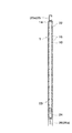
図1および図3に示す正面図においては、外壁材17および縦胴縁9並びに断熱材18を除いて、粘弾性体付き制振装置1を取付けた制振装置付き耐力壁23が、下部構造体としてのコンクリート製基礎26aと、上部構造としての側根太(または端根太)25aとの間に介在され、耐力壁22の下部横枠材21がアンカーボルトによりコンクリート基礎26aに固定され、上部横枠材21が側根太(または端根太)25aにドリルねじ等の固着具により固定されている状態が示されている。
In the front view shown in FIG. 1 and FIG. 3, except for the
そして、粘弾性体付き制振装置1は、構造用面状部材14あるいは面状部材15等の面状部材を有する耐力壁22における横方向に隣り合う各面状部材14(15)に取り付けることにより、粘弾性体付き制振装置1を備えた制振装置付き耐力壁23を容易に構成することができる。
And the damping
粘弾性体付き制振装置1を取り付ける構造としては、図示のように、隣り合う面状部材14(15)の端部に近い位置に取り付ければよく、面材のずれが最も大きく期待でき粘弾性体5のせん断変形が大きく、大きな減衰性能を期待できる面状部材14(15)の端部接合部が最もよい。図1または図2等に示すように、一つの耐力壁22における隣り合う面材14に取付けても良く、後記する図11に示す実施形態のように、独立した耐力壁22における面材14に取付けても良い。粘弾性体付き制振装置1を固定する場合、本発明では、面状部材14(15)の剛性が保たれれば、構造用面状部材14以外の面材でもよい。また、粘弾性体付き制振装置1を面状部材14に固定すると共に、その面状部材14を取付けている縦枠材10等に固定してもよい。
As shown in the figure, the structure for attaching the
また、粘弾性体付き制振装置1は、前記のように一方のカバープレート3における上下方向の両端部に切り欠き部6を備えており、その切り欠き部6の部分を利用して、縦胴縁9を耐力壁22における縦枠材10にドリルねじ13により粘弾性体5を貫通することなく容易に取付けることができ、また、縦胴縁9を前記縦枠材10に固定する場合に、ドリルねじ13等の固着具が前記粘弾性体5から離れた位置に設けられるので、粘弾性体5のせん断変形を阻害することはなく、粘弾性体5のせん断変形による減衰性能を発揮することができる。
In addition, the
また、隣り合う面状部材14,14に固定する構造とするために、粘弾性体付き制振装置1は、粘弾性体5を含む部材厚さ方向の寸法が薄くなるように各取付け部は平行な面にするのがよく、図示形態では各取付け部2a,2bは同面上とされ、外断熱工法における構造用面状部材14と外壁材17との間に配置可能な薄型の小型にされており、外断熱材18の厚さ寸法以内において設置可能にされている。
Moreover, in order to set it as the structure fixed to the adjacent
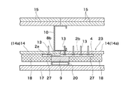
さらに説明すると、断熱材18の厚さの1/2以下程度とされた粘弾性体付き制振装置1における一方のカバープレート3における取付部2aと、他方のカバープレート4における取付部2bは、隣り合う面状部材14,14にドリルねじ13により取付けられている。隣り合う構造用面状部材14,14のドリルねじ13等による縦枠材10へ接合される接合部(面材境界端部の接合部)は、図12に示すように、水平力Fが作用した場合、上下方向の変位(面材長手方向の変位))が大きい位置であり、粘弾性体5のせん断変形を最大に期待できる位置である。
More specifically, the
各粘弾性体付き制振装置1は、直列に配置され、上位の粘弾性体付き制振装置1が下位の粘弾性体付き制振装置1に当接または近接して配置されている。また、前記各粘弾性体付き制振装置1における他方のカバープレート4は、基端側取付部2aおよび粘弾性体固着部8を含めて、他方の面状部材14の端部から突出しないように配置され、また、一方のカバープレート3は、一方の面状部材14の端部に固定されると共に、他方のカバープレート4の正面領域に跨るように粘弾性体固着部8は配置されて、各カバープレート3,4における取付部2a,2bが、それぞれ面状部材14,14に取付けられている。
The damping
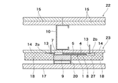
また、粘弾性体付き制振装置1を構造用面材14に固定するように設置した後、断熱材を兼ねた木製の縦胴縁9を、粘弾性体非固着部8aおよび粘弾性体固着部8に跨るように屋外側に配置して、前記の切り欠き部6の位置で、ドリルねじ13により他方の構造用面材14を貫通して縦枠材10に固定され、また、前記の断熱材18の側縁部内側を段状に切り欠くことで凹部27を形成し、このような断熱材18を他方の構造用面状部材14の屋外側に、前記粘弾性体付き制振装置1の外側を被覆するように、かつ縦胴縁9側面に当接設置し、各面状部材14,15および粘弾性体付き制振装置1を被覆するように設け、一方のカバープレート3の外側の粘弾性体固着部8の幅寸法以下の横幅寸法の縦胴縁9を当接配置し、前記縦胴縁9を耐力壁22における縦枠材10に固定している。
Moreover, after installing the damping
また、前記縦胴縁9に、鋼製各パイプ部材等の下地材としての通気留め付け金具20が、前記縦胴縁9等に固定され、前記通気留め付け金具20を介して、外壁材17が縦胴縁9に保持される構造とされ、外壁材17内側が通気性のある構造とされている。
Further, a ventilation fastening metal fitting 20 as a base material of each steel pipe member or the like is fixed to the
前記のように隣り合う面状部材14,14の前記境界端部の接合部に、粘弾性体付き制振装置1を取り付けると、図12に示すように、地震時等に建物に水平力Fが作用して、耐力壁22における縦枠材10と横枠材21により構成されたフレーム29が菱形に変形した場合、構造用面状部材14,14の硬さ(剛性)が保たれた状態で、構造用面材14が面外方向、部材長手方向、部材幅方向に変形することなく、隣り合う面状部材14,14の内側境界端部相互は、相対的に上下方向(部材長手方向)の位置ずれを生じ(図示では、左右の面状部材14,15は、左側の面状部材14に対して右側の面状部材が上方向に位置ずれを生じるようになり、また逆方向の水平力が作用した場合は逆に位置ずれを生じるようになり)、このような隣り合う面状部材14,14の位置ずれを生じる場合に、粘弾性体5にせん断変形させることで、エネルギーを粘弾性体5に吸収させ減衰効果を発揮させることができ、この減衰効果により、地震時の建物の応答層せん断力が減少させることができる。前記の応答層せん断力を減少させることができることは、建物の設計用地震力を低減できることになるため、必要壁量の低減、経費の低減が可能になる。したがって、安価な制振性能のよい建物とすることができる。
When the
例えば、アクリル系の粘弾性体5を用いた場合、粘弾性体付き制振装置1の外形が7.6×170×450mm(粘弾性体5の、厚みと、幅と、長さが、それぞれ3.0×80×380mm)であれば、これを図1に示すように5台直列に設置した耐力壁22のせん断変形角が1/500rad時では、25℃,1Hzで15%程度の減衰が期待でき、減衰が15%あれば、応答層せん断力は、鉄骨造で通常用いる減衰2%の場合の0.4倍まで低減されるため、前記のようなスチールハウスに適用した場合、実用上、格段の作用効果となる。
For example, when an acrylic
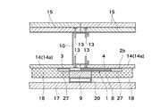
前記実施形態においては、外断熱工法における屋外側の構造用面状部材14に、粘弾性体付き制振装置1を取り付ける形態を示したが、本発明を実施する場合、室内側において隣り合う各面状部材に、粘弾性体付き制振装置1における各取付部を、ドリルねじ等の固着具により取付けてもよいので、このような形態について、図11を参照して説明する。
In the said embodiment, although the form which attaches the damping
図11は、前記実施形態の変形形態を示したもので、耐力壁22における屋外側において隣り合う構造用面状部材14に、粘弾性体付き制振装置1における一側部および他側部の取付部2a,2bが、それぞれ構造用面状部材14に取付けられている点は、前記実施形態と同様である。さらにこの変形形態では、横方向に独立した耐力壁22における構造用面状部材14に取付けている形態であり、屋内側(室内側)における横方向に隣り合う耐力壁22の各構造用面状部材14に、粘弾性体付き制振装置1における取付け部2a,2bが、それぞれ取付けられている。また、この形態では、粘弾性体付き制振装置1におけるそれぞれの取付け部2a,2bに、屋内側の面状部材15として、石膏ボード15aからなる面材15に固定され、また、室内側の面状部材15は、縦枠材10および横枠材21に前記の屋外側の構造用面状部材14と同様にドリルねじ(図示を省略した)により固定されている。
なお、図11に示す形態では、断熱材18と外壁材17との間に、通気空間19を設けていない形態であり、外壁材17は縦胴縁9に固着具により固定される。
FIG. 11 shows a modification of the above-described embodiment. The structural
In the form shown in FIG. 11, the
また、前記の変形形態として、屋内側に構造用面状部材等の面材を配置する形態の1つの耐力壁における隣り合う各面材、または隣り合う耐力壁間における横方向に隣り合う各面状部材に、それぞれ粘弾性体付き制振装置における一方または他方の取付部を取り付けるようにしてもよい。 Further, as the above-described modification, each adjacent surface material in one load bearing wall in a form in which a surface material such as a structural planar member is disposed indoors, or each surface adjacent in the lateral direction between adjacent load bearing walls You may make it attach the one or other attachment part in a damping device with a viscoelastic body to a shape member, respectively.
室内側に粘弾性体付き制振装置を取付ける耐力壁における面状部材としては、構造用面材が望ましいが、構造用面状部材以外でも、剛性が期待できる面材に粘弾性体付き制振装置1を取付けてもよく、例えば、構造用合板、スラグセグメントパーライト板、鋼板または石膏ボードのいずれか一つ以上の部材よりなる面材であればよい。また、隣り合う面状部材は、異なる材質の面状部材であってもよい。
As the planar member for the bearing wall to which the damping device with viscoelastic body is mounted on the indoor side, a structural face material is desirable, but other than the structural planar member, a vibration damping material with viscoelastic body can be applied to a face material that can be expected to have rigidity. The
前記実施形態では、横方向に隣り合う面状部材同士の接合部に粘弾性体付き制振装置1を取り付ける形態を示したが、図10に黒く矩形状に示すような位置に、それぞれ粘弾性体付き制振装置1を配置してもよい。図10に示す形態の粘弾性体付き制振装置1の配置例では、該装置を取り付ける面状部材同士の接合部は、横方向または縦方向に隣り合う面状部材のいずれでもよい構成としている。
横方向に隣り合う面状部材同士の接合部は、図12に示すように、地震時等に水平力Fが作用して隣り合う面状部材14と14の間に、相対的な上下方向の位置ずれを生じ、縦方向に配置した粘弾性体5がせん断変形することで入力エネルギーを吸収させ、減衰効果を発揮させることができる。
また、縦方向に隣り合う面状部材同士の接合部にも横方向に粘弾性体付き制振装置1を配置しても前記と同様の機構(図示を省略した)により説明することができる。水平力Fが作用して縦方向に隣り合う面状部材14,14’(面状部材14の縦方向の隣に位置する面状部材を14’とする(図10参照)。)の間には、相対的な水平方向の位置ずれを生じ、横方向に配置した粘弾性体5がせん断変形することで入力エネルギーを吸収させ、減衰効果を発揮させることができる。
In the said embodiment, although the form which attaches the damping
As shown in FIG. 12, the joint between the planar members adjacent to each other in the horizontal direction has a relative vertical direction between the adjacent
Moreover, even if the viscoelastic body-equipped damping
また、粘弾性体付き制振装置1の取付け位置としては、図10右端側または左端側から2番目の位置のように、建物30におけるコーナー部における隣合う面状部材の一方または他方の耐力壁22に取り付けて、制振装置付き耐力壁23としてもよい。この場合には、コーナー部における隣り合う一方の耐力壁22前面側と、他方の耐力壁22における側端部とを、同面上に配置することにより、粘弾性体付き制振装置1の各取付部を取り付けることができる。
なお、本発明では、面状部材としては、構造用合板、スラグセグメントパーライト板、鋼板または石膏ボードのいずれか一つ以上の部材よりなる面材でもよく、このような面材と枠材とからなる面版状のパネルであってもよい。
Moreover, as a mounting position of the damping
In the present invention, the planar member may be a structural plywood, a slag segment pearlite plate, a steel plate or a plaster board made of any one or more members, and from such a surface material and a frame material. A surface plate-like panel may be used.
前記した本発明の実施形態の改良点を列記すると、以下のようになる。
(1)面状部材の硬さ(せん断変形のし難さ)(剛性)に注目して、面状部材同士の各接合部のずれを最大限に利用して、粘弾性体のせん断変形による減衰を効果的に発揮可能になっている。
(2)粘弾性体付き制振装置は、屋外側の面状部材表面にも屋内側の面状部材表面にも設置可能になっている薄型で小型とされている。
(3)粘弾性体付き制振装置が屋外側の面状部材表面に固定される場合、粘弾性体を通気胴縁と縦枠材の接接合位置に固定しないため、粘弾性体のせん断変形による減衰を効果的に発揮可能にされている。
(4)粘弾性体を仕組んで部品化した、粘弾性体付き制振装置をあらかじめ工場で製作し、ユニット化されているので、施工現場で取り付けるだけでよいため、粘弾性体の圧着・封入に関する現場施工の困難さを回避可能にしている。
(5)外張り断熱工法において、粘弾性体を断熱材の内側に入れることにより、熱の影響を排除することで、温度依存性のある粘弾性体でも使用可能になり、その減衰効果を十分に発揮可能になっている。
(6)粘弾性体の減衰効果により、地震時の建物の応答層せん断力が減少するため、建物の設計用地震力を低減でき、建物の必要壁量の低減が可能になり、制振性能を有する建物を短工期で施工可能で安価に構築することができる。
The improvements of the above-described embodiment of the present invention are listed as follows.
(1) Paying attention to the hardness (difficulty of shear deformation) (rigidity) of the planar member, by utilizing the displacement of each joint between the planar members to the maximum, by shear deformation of the viscoelastic body Attenuation can be effectively exhibited.
(2) The vibration damping device with a viscoelastic body is thin and small and can be installed on the surface of the planar member on the outdoor side or on the surface of the planar member on the indoor side.
(3) When the vibration damping device with a viscoelastic body is fixed to the surface of the planar member on the outdoor side, the viscoelastic body is not fixed at the contact position between the ventilator edge and the vertical frame member, so the shear deformation of the viscoelastic body It is possible to effectively exhibit the attenuation by.
(4) Viscoelastic body damping device with viscoelastic body made into parts, manufactured in advance at the factory and unitized, so it only needs to be installed at the construction site. It is possible to avoid the difficulty of construction on site.
(5) In the veneer insulation method, by inserting the viscoelastic body inside the heat insulating material, it is possible to use a temperature-dependent viscoelastic body by eliminating the influence of heat, and its damping effect is sufficient It has become possible to demonstrate.
(6) Since the response layer shear force of the building during an earthquake is reduced due to the damping effect of the viscoelastic body, the seismic force for building design can be reduced, and the required wall amount of the building can be reduced. It is possible to construct a building having a short construction period and to construct it at a low cost.
1 粘弾性体付き制振装置
2a 取付部
2b 取付部
3 カバープレート
4 カバープレート
5 粘弾性体
6 切り欠き部
7 縦部分
8 粘弾性体固着部
9 縦胴縁
10 縦枠材
11 接合用孔
13 ドリルねじ
14 構造用面状部材
15 面状部材
16 粘弾性体固着部
17 外壁材
18 断熱材
19 通気空間
20 通気留め付け金具
21 横枠材
22 耐力壁
23 制振装置付き耐力壁
24 ホールダウン金物
25 上部構造部材
26 下部構造
26a コンクリート製基礎
27 凹部
29 フレーム
30 建物
DESCRIPTION OF
Claims (10)
Priority Applications (1)
| Application Number | Priority Date | Filing Date | Title |
|---|---|---|---|
| JP2006039619A JP4774310B2 (en) | 2006-02-16 | 2006-02-16 | Bearing wall with damping device with damping device with viscoelastic body |
Applications Claiming Priority (1)
| Application Number | Priority Date | Filing Date | Title |
|---|---|---|---|
| JP2006039619A JP4774310B2 (en) | 2006-02-16 | 2006-02-16 | Bearing wall with damping device with damping device with viscoelastic body |
Publications (2)
| Publication Number | Publication Date |
|---|---|
| JP2007217954A true JP2007217954A (en) | 2007-08-30 |
| JP4774310B2 JP4774310B2 (en) | 2011-09-14 |
Family
ID=38495531
Family Applications (1)
| Application Number | Title | Priority Date | Filing Date |
|---|---|---|---|
| JP2006039619A Active JP4774310B2 (en) | 2006-02-16 | 2006-02-16 | Bearing wall with damping device with damping device with viscoelastic body |
Country Status (1)
| Country | Link |
|---|---|
| JP (1) | JP4774310B2 (en) |
Cited By (7)
| Publication number | Priority date | Publication date | Assignee | Title |
|---|---|---|---|---|
| JP2008111331A (en) * | 2008-01-24 | 2008-05-15 | Nippon Steel Corp | Building with joint metal |
| JP2008111332A (en) * | 2008-01-24 | 2008-05-15 | Nippon Steel Corp | Joint metal |
| JP2009046923A (en) * | 2007-08-22 | 2009-03-05 | Jutaku Kozo Kenkyusho:Kk | Vibration control member and wall frame reinforced by means of vibration control |
| WO2009093712A1 (en) * | 2008-01-24 | 2009-07-30 | Nippon Steel Corporation | Connection metal fitting and building with the same |
| JP2011001815A (en) * | 2010-07-15 | 2011-01-06 | Nippon Steel Corp | Building with joint metal |
| JP2016186193A (en) * | 2015-03-27 | 2016-10-27 | 旭化成ホームズ株式会社 | Construction method for exterior wall structure and exterior wall structure |
| JP2018003351A (en) * | 2016-06-29 | 2018-01-11 | 泰久 志築 | Reinforcement structure for building |
Families Citing this family (1)
| Publication number | Priority date | Publication date | Assignee | Title |
|---|---|---|---|---|
| JP6363588B2 (en) * | 2015-12-21 | 2018-07-25 | 日鉄住金鋼板株式会社 | building |
Citations (3)
| Publication number | Priority date | Publication date | Assignee | Title |
|---|---|---|---|---|
| JPH07331923A (en) * | 1994-06-14 | 1995-12-19 | Asahi Chem Ind Co Ltd | Construction of rigidity adjustable panel and fitting method thereof |
| JP2001295506A (en) * | 2000-04-12 | 2001-10-26 | Shimizu Corp | Seismic control damper and its manufacturing method |
| JP2004169333A (en) * | 2002-11-18 | 2004-06-17 | Panahome Corp | Vibration-proofing structure of wall |
-
2006
- 2006-02-16 JP JP2006039619A patent/JP4774310B2/en active Active
Patent Citations (3)
| Publication number | Priority date | Publication date | Assignee | Title |
|---|---|---|---|---|
| JPH07331923A (en) * | 1994-06-14 | 1995-12-19 | Asahi Chem Ind Co Ltd | Construction of rigidity adjustable panel and fitting method thereof |
| JP2001295506A (en) * | 2000-04-12 | 2001-10-26 | Shimizu Corp | Seismic control damper and its manufacturing method |
| JP2004169333A (en) * | 2002-11-18 | 2004-06-17 | Panahome Corp | Vibration-proofing structure of wall |
Cited By (11)
| Publication number | Priority date | Publication date | Assignee | Title |
|---|---|---|---|---|
| JP2009046923A (en) * | 2007-08-22 | 2009-03-05 | Jutaku Kozo Kenkyusho:Kk | Vibration control member and wall frame reinforced by means of vibration control |
| JP2008111331A (en) * | 2008-01-24 | 2008-05-15 | Nippon Steel Corp | Building with joint metal |
| JP2008111332A (en) * | 2008-01-24 | 2008-05-15 | Nippon Steel Corp | Joint metal |
| WO2009093712A1 (en) * | 2008-01-24 | 2009-07-30 | Nippon Steel Corporation | Connection metal fitting and building with the same |
| JP4664997B2 (en) * | 2008-01-24 | 2011-04-06 | 新日本製鐵株式会社 | Buildings with joint hardware |
| JP4664998B2 (en) * | 2008-01-24 | 2011-04-06 | 新日本製鐵株式会社 | Bonded hardware |
| TWI396790B (en) * | 2008-01-24 | 2013-05-21 | Nippon Steel & Sumitomo Metal Corp | Metal joint and architecture comprising the same |
| US8511025B2 (en) | 2008-01-24 | 2013-08-20 | Nippon Steel & Sumitomo Metal Corporation | Metal joint and building comprising the same |
| JP2011001815A (en) * | 2010-07-15 | 2011-01-06 | Nippon Steel Corp | Building with joint metal |
| JP2016186193A (en) * | 2015-03-27 | 2016-10-27 | 旭化成ホームズ株式会社 | Construction method for exterior wall structure and exterior wall structure |
| JP2018003351A (en) * | 2016-06-29 | 2018-01-11 | 泰久 志築 | Reinforcement structure for building |
Also Published As
| Publication number | Publication date |
|---|---|
| JP4774310B2 (en) | 2011-09-14 |
Similar Documents
| Publication | Publication Date | Title |
|---|---|---|
| JP4774310B2 (en) | Bearing wall with damping device with damping device with viscoelastic body | |
| JP6583348B2 (en) | Wall member and foundation joint structure | |
| JP4598690B2 (en) | Refractory panel and boundary wall structure using the same | |
| JP6379310B1 (en) | Damping unit, damping device and building | |
| JP2010018971A (en) | Fire resistant covering structure of steel column | |
| JP2005036583A (en) | Mounting structure of heat insulating material | |
| JP6196455B2 (en) | Exterior wall structure | |
| JP2002030828A (en) | Brace damper | |
| JP5423633B2 (en) | Reinforcing panel and reinforcing structure | |
| JP4460753B2 (en) | Damping structure of buildings | |
| JP2009155857A (en) | Vibration control structure of building, and joint member | |
| JP7217144B2 (en) | damping mechanism for building | |
| JP7164080B2 (en) | Skylight structure and skylight construction method | |
| JP6782058B1 (en) | Construction method of a wooden building using a perforated sheet-covered PC plate | |
| JP6120438B2 (en) | Junction structure | |
| JP2010007311A (en) | Vibration damper | |
| JP2009243088A (en) | Installation structure of vibration damping panel | |
| JP4120820B2 (en) | Structure and construction method of fire protection wall | |
| JP2011231491A (en) | Attic space parting wall and attic space parting wall construction method | |
| JP4030576B1 (en) | Wooden shear wall | |
| JP6998137B2 (en) | Fireproof building structure and receiving members | |
| JP2009079456A (en) | Vibration control structure | |
| JP2005127030A (en) | Vibration control wall structure | |
| JP6651774B2 (en) | Damping unit and damping device | |
| JP2011252302A (en) | Panel for bearing wall |
Legal Events
| Date | Code | Title | Description |
|---|---|---|---|
| A621 | Written request for application examination |
Free format text: JAPANESE INTERMEDIATE CODE: A621 Effective date: 20080122 |
|
| A977 | Report on retrieval |
Free format text: JAPANESE INTERMEDIATE CODE: A971007 Effective date: 20101130 |
|
| A131 | Notification of reasons for refusal |
Free format text: JAPANESE INTERMEDIATE CODE: A131 Effective date: 20110118 |
|
| A521 | Written amendment |
Free format text: JAPANESE INTERMEDIATE CODE: A523 Effective date: 20110317 |
|
| TRDD | Decision of grant or rejection written | ||
| A01 | Written decision to grant a patent or to grant a registration (utility model) |
Free format text: JAPANESE INTERMEDIATE CODE: A01 Effective date: 20110614 |
|
| A01 | Written decision to grant a patent or to grant a registration (utility model) |
Free format text: JAPANESE INTERMEDIATE CODE: A01 |
|
| A61 | First payment of annual fees (during grant procedure) |
Free format text: JAPANESE INTERMEDIATE CODE: A61 Effective date: 20110627 |
|
| FPAY | Renewal fee payment (event date is renewal date of database) |
Free format text: PAYMENT UNTIL: 20140701 Year of fee payment: 3 |
|
| R150 | Certificate of patent or registration of utility model |
Free format text: JAPANESE INTERMEDIATE CODE: R150 Ref document number: 4774310 Country of ref document: JP Free format text: JAPANESE INTERMEDIATE CODE: R150 |
|
| S533 | Written request for registration of change of name |
Free format text: JAPANESE INTERMEDIATE CODE: R313533 |
|
| FPAY | Renewal fee payment (event date is renewal date of database) |
Free format text: PAYMENT UNTIL: 20140701 Year of fee payment: 3 |
|
| R350 | Written notification of registration of transfer |
Free format text: JAPANESE INTERMEDIATE CODE: R350 |
|
| FPAY | Renewal fee payment (event date is renewal date of database) |
Free format text: PAYMENT UNTIL: 20140701 Year of fee payment: 3 |
|
| S533 | Written request for registration of change of name |
Free format text: JAPANESE INTERMEDIATE CODE: R313533 |
|
| FPAY | Renewal fee payment (event date is renewal date of database) |
Free format text: PAYMENT UNTIL: 20140701 Year of fee payment: 3 |
|
| R350 | Written notification of registration of transfer |
Free format text: JAPANESE INTERMEDIATE CODE: R350 |
|
| R250 | Receipt of annual fees |
Free format text: JAPANESE INTERMEDIATE CODE: R250 |
|
| R250 | Receipt of annual fees |
Free format text: JAPANESE INTERMEDIATE CODE: R250 |
|
| R250 | Receipt of annual fees |
Free format text: JAPANESE INTERMEDIATE CODE: R250 |
|
| S111 | Request for change of ownership or part of ownership |
Free format text: JAPANESE INTERMEDIATE CODE: R313117 |
|
| R350 | Written notification of registration of transfer |
Free format text: JAPANESE INTERMEDIATE CODE: R350 |
|
| S533 | Written request for registration of change of name |
Free format text: JAPANESE INTERMEDIATE CODE: R313533 |
|
| R350 | Written notification of registration of transfer |
Free format text: JAPANESE INTERMEDIATE CODE: R350 |