JP2007204092A - Closing mechanism for container mouth - Google Patents
Closing mechanism for container mouth Download PDFInfo
- Publication number
- JP2007204092A JP2007204092A JP2006023391A JP2006023391A JP2007204092A JP 2007204092 A JP2007204092 A JP 2007204092A JP 2006023391 A JP2006023391 A JP 2006023391A JP 2006023391 A JP2006023391 A JP 2006023391A JP 2007204092 A JP2007204092 A JP 2007204092A
- Authority
- JP
- Japan
- Prior art keywords
- cap
- cylindrical mouth
- inner lid
- mouth portion
- cylindrical
- Prior art date
- Legal status (The legal status is an assumption and is not a legal conclusion. Google has not performed a legal analysis and makes no representation as to the accuracy of the status listed.)
- Pending
Links
Images


Abstract
Description
本発明は、容器本体に設けられた筒状口部と、当該筒状口部を閉止するキャップの組み合わせからなる容器口部の閉止機構に関する。 The present invention relates to a container mouth closing mechanism comprising a combination of a cylindrical mouth provided in a container body and a cap for closing the cylindrical mouth.
内容物の取出し口(注出口)として機能する筒状口部と、該筒状口部を閉止するキャップとを備えた容器は、液体飲料、流動性食品、調味料等を収容する容器として広く用いられている。このような容器において、キャップと筒状口部の嵌合のみで口部を閉止する場合、嵌合部の成形不良やキズなどによって、内容物の漏れが生じる懸念がある。また、容器内に内容物を充填し、容器密閉後、高温加熱殺菌するレトルト処理を行う場合には、レトルト処理時の容器内の圧力上昇により、内容物が漏れてしまうおそれがある。さらに、レトルト処理によるキャップと筒状口部の収縮・膨張率に差があると、口部のキャップによる閉止が不十分となり、内容物が漏れてしまうおそれもある。 A container having a cylindrical mouth portion functioning as a content outlet (pour port) and a cap for closing the cylindrical mouth portion is widely used as a container for storing liquid beverages, liquid foods, seasonings and the like. It is used. In such a container, when the mouth is closed only by fitting the cap and the cylindrical mouth, there is a concern that the contents may leak due to poor molding or scratching of the fitting. Moreover, when filling the contents in the container and performing a retort process in which the container is sealed and then heat sterilized at a high temperature, the contents may leak due to an increase in pressure in the container during the retort process. Furthermore, if there is a difference in the shrinkage / expansion rate between the cap and the cylindrical mouth portion due to the retort process, the mouth portion is not sufficiently closed by the cap and the contents may leak.
従来、この筒状口部を備えた容器の密封性を向上させるため、口部と接着可能なインナーシール材を用いて、口部を封止することが行われてきた。しかしながら、インナーシール材によって封止された容器から内容物を取り出すためには、まずキャップを開栓し、さらに口部に接着しているインナーシール材を口部から剥離しなければならず、手間がかかるものであった。 Conventionally, in order to improve the sealing performance of a container provided with this cylindrical mouth portion, it has been performed to seal the mouth portion using an inner seal material that can be bonded to the mouth portion. However, in order to take out the contents from the container sealed with the inner seal material, the cap must first be opened, and the inner seal material adhered to the mouth portion must be peeled off from the mouth portion. It took.
そこで、キャップの開栓と同時に、インナーシール材が口部から剥離されるようにした容器が提案されている。例えば、特許文献1及び特許文献2には、インナーシール材を口部とキャップ内面の両方に接着し、インナーシール材とキャップ内面との接着力をインナーシール部材と口部との接着力よりも大きくすることで、キャップを開栓するとインナーシール部材はキャップ内面との接着状態を保持したまま、自動的に口部から剥離されるようにした密封装置が記載されている。
Therefore, a container has been proposed in which the inner seal material is peeled off from the mouth portion at the same time as opening the cap. For example, in
しかしながら、特許文献1及び特許文献2のように、キャップの回転によって口部とインナーシール材との界面に剪断力を生じさせ、インナーシール材を口部から剥離するためには、大きな力を要するという問題がある。
However, as in
一方、特許文献3には、キャップシェルの内部に容器口部の内周面と密着する垂直シール(インナーパッキン)を有する中栓を備え、この中栓がキャップシェルの上昇に追従しないような構造とすることで、タンパーエビデントバンドとキャップ本体とをつなぐ弱化部が破断される前に、キャップの密封性が解除されないようにしたタンパーエビンデント性を有するプラスチックキャップが記載されている。
また、特許文献4には、円形状の天板及び該天板の周縁から垂下されたスカート壁及びタンパーエビデンスバンドを有するシェルと、当該シェル内に挿入されて容器の口部を密封するパッキンとからなる合成樹脂製のピルファープルーフキャップが開示されている。このキャップは、開栓時に上記密封用パッキンを持ち上げるパッキン案内部を備えており、当該パッキン案内部による密封用パッキンの持ち上げによって密封用パッキンの中足が容器口部の気密機能を逸するまでの間は、タンパーエビデンスバンドのブリッジが切断されても、容器の気密性が維持されるようになっている。
特許文献3及び特許文献4のキャップは、インナーパッキンとして機能する垂直シール(中足)や、必要に応じて設けても良い外側シール(アウターパッキン)によって、キャップの密封性を保持するものであり、密封性が不十分であり、特にレトルト処理に対応することができない。
On the other hand, Patent Document 3 includes an inner plug having a vertical seal (inner packing) in close contact with the inner peripheral surface of the container mouth inside the cap shell, and the inner plug does not follow the rise of the cap shell. Thus, there is described a plastic cap having a tamper-evident property in which the sealing performance of the cap is not released before the weakened portion connecting the tamper-evident band and the cap body is broken.
The caps of Patent Document 3 and
本発明は上記実情を鑑みて成し遂げられたものであり、キャップの回転による剪断力でインナーシール材を剥離する方法と比較して、小さな力でキャップの開栓と同時にインナーシール材を口部から剥離することができ、且つ、レトルト処理にも対応可能な容器口部の閉止機構を提供することを目的とする。 The present invention has been accomplished in view of the above circumstances, and the inner seal material is removed from the mouth at the same time as opening the cap with a small force, compared to the method of peeling the inner seal material by shearing force due to rotation of the cap. An object of the present invention is to provide a container mouth closing mechanism that can be peeled off and can be used for retort processing.
本発明の容器口部の閉止機構は、容器本体に設けられた筒状口部と、該筒状口部を閉止するキャップとの組み合わせからなる容器口部の閉止機構であって、前記キャップは、天板部、及び、該天板部の周縁から垂下し、前記筒状口部の側面を覆うスカート部を有すると共に、該スカート部の内面に前記筒状口部の外面に設けられたネジ部と螺合するネジ部を有し、前記筒状口部の側面に沿って回転しながら上下動することが可能なキャップ本体と、前記キャップ本体内部の天板部近傍に該キャップ本体と分離しないように嵌合され、且つ、前記筒状口部の上端面と当接する当接面を有する天部を有し、前記筒状口部の上端開口部を覆って該筒状口部を閉鎖するキャップ中蓋と、からなり、前記キャップ中蓋の天部と前記筒状口部の上端面とが前記当接面において接着しており、前記キャップ本体と前記キャップ中蓋は、該キャップ中蓋を回転させずに該キャップ本体を回転させることができる互いに独立した部材であり、前記キャップ本体を前記筒状口部の側面に沿って回転させて該筒状口部上端方向へ移動させるときに、該キャップ本体が該キャップ中蓋と摺動可能な状態で係合し該キャップ中蓋を押し上げることにより、前記キャップ中蓋の天部と前記筒状口部の上端面との接着が解け、前記筒状口部が開放されることを特徴とするものである。 The container mouth closing mechanism of the present invention is a container mouth closing mechanism comprising a combination of a cylindrical mouth provided in a container body and a cap for closing the cylindrical mouth, wherein the cap A top plate portion, and a screw that hangs from the periphery of the top plate portion and covers the side surface of the cylindrical mouth portion, and is provided on the inner surface of the skirt portion on the outer surface of the cylindrical mouth portion A cap body that has a threaded portion to be screwed together and can move up and down while rotating along the side surface of the cylindrical mouth portion, and is separated from the cap body in the vicinity of the top plate portion inside the cap body A top portion having a contact surface that is fitted so as not to be in contact with an upper end surface of the cylindrical mouth portion, covers the upper end opening of the cylindrical mouth portion, and closes the cylindrical mouth portion A cap inner lid, and a top portion of the cap inner lid and an upper end surface of the cylindrical mouth portion. The cap main body and the cap inner lid are independent members that can rotate the cap main body without rotating the cap inner lid, and the cap main body is attached to the abutting surface. When the cap body is rotated along the side surface of the cylindrical mouth portion and moved toward the upper end of the cylindrical mouth portion, the cap body engages with the cap inner lid in a slidable state and pushes up the cap inner lid. Thus, the top part of the cap inner lid and the upper end surface of the cylindrical mouth part are unbonded, and the cylindrical mouth part is opened.
本発明の容器口部の閉止機構は、前記キャップ本体を前記筒状口部の側面に沿って回転させて該筒状口部の上端方向へ移動させる際に、該キャップ本体とキャップ中蓋とが係合する係合面に働く筒状口部の上端方向への力を、該キャップ中蓋を押し上げて前記筒状口部と該キャップ中蓋(キャップ)との接着を解く力として利用するものである。このとき、キャップ本体は、キャップ中蓋との係合面に対して摺動しながら回転し、該キャップ中蓋を押し上げるので、キャップ中蓋と筒状口部との接着面に剪断力がほとんど生じない。従って、本発明によれば、口部とキャップとの接着面に剪断力を生じさせることによりキャップと口部との接着を解く従来のキャップと比べて、小さな力でキャップ本体を回転させることができ、容易にキャップを開栓することが可能である。また、キャップと筒状口部とを接着させて密封させているため、密封性に優れるものである。 The container mouth portion closing mechanism according to the present invention is configured such that when the cap body is rotated along the side surface of the cylindrical mouth portion and moved toward the upper end of the cylindrical mouth portion, the cap body, the cap inner lid, The force in the upper end direction of the cylindrical mouth portion acting on the engaging surface with which the cap engages is used as a force for pushing up the cap inner lid and releasing the adhesion between the cylindrical mouth portion and the cap inner lid (cap). Is. At this time, the cap body rotates while sliding with respect to the engagement surface with the cap inner lid and pushes up the cap inner lid, so that almost no shearing force is applied to the adhesive surface between the cap inner lid and the cylindrical mouth portion. Does not occur. Therefore, according to the present invention, it is possible to rotate the cap body with a small force as compared with the conventional cap that releases the bond between the cap and the mouth by generating a shearing force on the bonding surface between the mouth and the cap. It is possible to open the cap easily. Moreover, since the cap and the cylindrical mouth are bonded and sealed, the sealing performance is excellent.
前記筒状口部と前記キャップ中蓋との接着形態は特に限定されないが、密封性及び開封容易性の観点から、前記キャップ中蓋の前記当接面に、前記筒状口部と前記キャップ中蓋とを接着するインナーシール材を備え、該インナーシール材を介して前記筒状口部と前記キャップ中蓋とが接着していることが好ましい。 The bonding form between the cylindrical mouth portion and the cap inner lid is not particularly limited. From the viewpoint of sealing performance and ease of opening, the cylindrical mouth portion and the cap inner lid are formed on the contact surface of the cap inner lid. It is preferable that an inner seal material for bonding the lid is provided, and the cylindrical mouth portion and the cap inner lid are bonded via the inner seal material.
前記キャップ中蓋が、前記筒状口部の上端開口部を覆って該筒状口部を閉鎖する構造は特に限定されず、前記キャップ中蓋の天部が、前記筒状口部の上端開口部を覆って該筒状口部を閉鎖する形状を有していてもよいし、前記キャップ中蓋の前記当接面に設けられたインナーシール材が、前記筒状口部の上端開口部を覆って該筒状口部を閉鎖する形状を有していてもよい。 The structure in which the cap inner lid covers the upper end opening of the cylindrical mouth portion and closes the cylindrical mouth portion is not particularly limited, and the top portion of the cap inner lid is the upper end opening of the cylindrical mouth portion. The cylindrical mouth portion may be closed and the inner seal material provided on the abutting surface of the cap inner lid may open the upper end opening of the cylindrical mouth portion. You may have a shape which covers and closes this cylindrical mouth part.
前記キャップ本体を前記筒状口部の側面に沿って回転させて筒状口部上端方向へ移動させたときに該キャップ本体と前記キャップ中蓋とが係合する係合面が、前記キャップ本体を前記筒状口部の側面に沿って回転させて最も下端側に移動させたときに、まったく接触しないような構成とする場合、キャップ回転開始時に必要な力が小さくなり、キャップの開封性を向上させることができる。 When the cap main body is rotated along the side surface of the cylindrical mouth portion and moved in the upper end direction of the cylindrical mouth portion, an engagement surface that engages the cap main body and the cap inner lid is the cap main body. When it is configured so that it does not contact at all when it is rotated along the side surface of the cylindrical mouth and moved to the lowermost side, the force required at the start of the cap rotation is reduced, and the cap can be opened. Can be improved.
また、前記キャップ本体が前記キャップ中蓋を押し上げる力を一箇所に集中させることで、キャップの開栓が容易となることから、前記キャップ本体を前記筒状口部の側面に沿って回転させて該筒状口部上端方向へ移動させるときに該キャップ本体と前記キャップ中蓋とが係合する位置の相対する係合面のどちらかに凸部が一箇所設けられていることが好ましい。 Further, since the cap main body concentrates the force that pushes up the cap inner lid in one place, the cap can be easily opened, so the cap main body is rotated along the side surface of the cylindrical mouth portion. It is preferable that a convex portion is provided at one of the opposing engagement surfaces at a position where the cap main body and the cap inner lid are engaged when moving in the upper end direction of the cylindrical mouth portion.
前記キャップ本体を前記筒状口部の側面に沿って回転させて該筒状口部上端方向へ移動させるときに前記キャップ中蓋と係合する該キャップ本体の係合面は、例えば、前記スカート部の内面に設けられたネジ部の一部により形成することができる。 When the cap body is rotated along the side surface of the cylindrical mouth portion and moved in the upper end direction of the cylindrical mouth portion, the engagement surface of the cap body that engages with the cap inner lid is, for example, the skirt It can form with a part of screw part provided in the inner surface of a part.
本発明により提供される容器口部の閉止機構は、キャップと筒状口部との螺合を解く際のキャップ本体の筒状口部上端方向への移動を、接着された筒状口部とキャップとの接着を解くための力に利用してキャップを開封するものであり、キャップと筒状口部との接着面にほとんど剪断力が生じない。そのため、キャップを回転させる際に、筒状口部とキャップとの接着面の界面に生じる剪断力によってキャップと口部との接着を解き、キャップを開封する従来の閉止機構と比較して、小さな力で楽に容器を開封することが可能である。また、キャップと筒状口部とが接着されているため、容器の密封性が高く、レトルト処理にも対応が可能である。 The container mouth closing mechanism provided by the present invention is configured to move the cap body toward the upper end of the cylindrical mouth when unscrewing the cap and the cylindrical mouth. The cap is opened using a force for unbonding with the cap, and almost no shearing force is generated on the bonding surface between the cap and the cylindrical mouth portion. Therefore, when rotating the cap, it is smaller than the conventional closing mechanism that opens the cap by releasing the cap and the mouth by the shearing force generated at the interface between the cylindrical mouth and the cap. It is possible to open the container easily with force. Further, since the cap and the cylindrical mouth are bonded, the container has high sealing performance and can cope with retort processing.
本発明の容器口部の閉止機構は、容器本体に設けられた筒状口部と、該筒状口部を閉止するキャップとの組み合わせからなる容器口部の閉止機構であって、前記キャップは、天板部、及び、該天板部の周縁から垂下し、前記筒状口部の側面を覆うスカート部を有すると共に、該スカート部の内面に前記筒状口部の外面に設けられたネジ部と螺合するネジ部を有し、前記筒状口部の側面に沿って回転しながら上下動することが可能なキャップ本体と、前記キャップ本体内部の天板部近傍に該キャップ本体と分離しないように嵌合され、且つ、前記筒状口部の上端面と当接する当接面を有する天部を有し、前記筒状口部の上端開口部を覆って該筒状口部を閉鎖するキャップ中蓋と、からなり、前記キャップ中蓋の天部と前記筒状口部の上端面とが前記当接面において接着しており、前記キャップ本体と前記キャップ中蓋は、該キャップ中蓋を回転させずに該キャップ本体を回転させることができる互いに独立した部材であり、前記キャップ本体を前記筒状口部の側面に沿って回転させて該筒状口部上端方向へ移動させるときに、該キャップ本体が該キャップ中蓋と摺動可能な状態で係合し該キャップ中蓋を押し上げることにより、前記キャップ中蓋の天部と前記筒状口部の上端面との接着が解け、前記筒状口部が開放されることを特徴とするものである。 The container mouth closing mechanism of the present invention is a container mouth closing mechanism comprising a combination of a cylindrical mouth provided in a container body and a cap for closing the cylindrical mouth, wherein the cap A top plate portion, and a screw that hangs from the periphery of the top plate portion and covers the side surface of the cylindrical mouth portion, and is provided on the inner surface of the skirt portion on the outer surface of the cylindrical mouth portion A cap body that has a threaded portion to be screwed together and can move up and down while rotating along the side surface of the cylindrical mouth portion, and is separated from the cap body in the vicinity of the top plate portion inside the cap body A top portion having a contact surface that is fitted so as not to be in contact with an upper end surface of the cylindrical mouth portion, covers the upper end opening of the cylindrical mouth portion, and closes the cylindrical mouth portion A cap inner lid, and a top portion of the cap inner lid and an upper end surface of the cylindrical mouth portion. The cap main body and the cap inner lid are independent members that can rotate the cap main body without rotating the cap inner lid, and the cap main body is attached to the abutting surface. When the cap body is rotated along the side surface of the cylindrical mouth portion and moved toward the upper end of the cylindrical mouth portion, the cap body engages with the cap inner lid in a slidable state and pushes up the cap inner lid. Thus, the top part of the cap inner lid and the upper end surface of the cylindrical mouth part are unbonded, and the cylindrical mouth part is opened.
以下、本発明の閉止機構について、図1〜図12を用いて説明する。
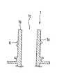
図1〜図3は、本発明を適用した、筒状口部と当該筒状口部を閉止するキャップの組み合わせからなる容器口部の閉止機構の一実施形態を示す断面図であって、図1は、筒状口部がキャップによって閉止されている状態を示す図、図2は図1における閉止機構のキャップのみを示す図、図3は図1における閉止機構の筒状口部のみを示す図である。また、図11は、図1の閉止機構を適用した内容物取出装置101の一形態例を示す正面図(11A)と側面図(11B)、図12は、図11の内容物取出装置101を取り付けた容器の一形態例を示す図である。
Hereinafter, the closing mechanism of the present invention will be described with reference to FIGS.
1 to 3 are cross-sectional views showing an embodiment of a closing mechanism for a container mouth portion composed of a combination of a cylindrical mouth portion and a cap for closing the tubular mouth portion, to which the present invention is applied. 1 is a view showing a state in which the cylindrical mouth portion is closed by a cap, FIG. 2 is a view showing only the cap of the closing mechanism in FIG. 1, and FIG. 3 is a view showing only the cylindrical mouth portion of the closing mechanism in FIG. FIG. 11 is a front view (11A) and a side view (11B) showing one embodiment of the content take-out
尚、本発明において筒状口部を備える容器は図12に示すものに限定されず、その材質は紙製、樹脂製、金属製、又はこれらの材質を複数組み合わせて用いてもよく、その形状もチューブ型、ボトル型、袋型等、特に限定されない。また、容器本体に設けられる筒状口部は、筒状であって、キャップによる閉止が可能であればよく、容器本体と一体型であっても、一体型でなくてもよい。また、筒状口部は、図11のような内容物取出装置に限定されず、一般的なチューブやボトルの注出口(注入口)として取り付けられるような構造の口部でもよい。 In the present invention, the container having the cylindrical mouth portion is not limited to that shown in FIG. 12, and the material thereof may be paper, resin, metal, or a combination of these materials. The tube type, bottle type, bag type and the like are not particularly limited. Moreover, the cylindrical mouth part provided in a container main body should just be cylindrical and can be closed by a cap, and may be integral with a container main body, or may not be integral. Further, the cylindrical mouth portion is not limited to the content take-out device as shown in FIG. 11, and may be a mouth portion having a structure attached as a general tube or bottle spout (injection port).
図11において、内容物取出装置101は、筒状口部1、導管部2、導管部2の上端において左右に張り出した一対の接合部3を少なくとも備えたストロー部4と、筒状口部1を閉止するキャップ5とからなる。筒状口部1は、図1及び図3に示すように、キャップ5(キャップ本体12)に設けられたネジ部(本実施形態においてはネジ溝)20と係合できるネジ部(本実施形態においてはネジ山)6をその側面1aに有し、キャップ5と螺合することによって閉止される。容器未開封時には、筒状口部1の上端開口部1cは、その上端面1bにおいて、キャップ5の内面(キャップ中蓋15)にインナーシール材19を介して接着しており、密封性が高く保たれている。図11のように、キャップ5(キャップ本体12)の側面部の外表面には、滑り止めとなる縦溝12b等が設けられていてもよい。
In FIG. 11, the content take-out
ストロー部4は、キャップ(キャップ中蓋)やインナーシール材との接着性の点で、通常、高密度ポリエチレン(HDPE)等のポリエチレン、ポリプロピレン等のプラスチック材料を射出成形することによって形成されるが、成形材料は特に制限されず、プラスチック以外の材料を用いてもよい。
筒状口部1には、内容物取出装置101を容器の製造工程途中で吊るための支持フランジ7、支持フランジ7を介して吊り上げた内容物取出装置101を整列するための整列リブ8等が設けられていても良い。また、導管部2には、上端部フランジ9や、内容物を効率よく充填又は取出すための内容物導出孔10が形成されていてもよい。
The
The
内容物取出装置101は、例えば、図12に示すように、フレキシブルな積層フィルムで作製されたガセット袋からなる容器本体11の上方開口部と、内容物取出装置101の接合部3を接合して用いることができる。この容器から内容物を取り出す際には、キャップ5と筒状口部1の螺合を解いてキャップ5を開栓し、筒状口部1を注出口として利用する。図12のように、導管部2の先端が容器本体11の底部付近にまで達する場合には、内容物取出装置101をストローとして利用することも可能であり、筒状口部1に口を付けて内容物を吸い上げることができる。
For example, as shown in FIG. 12, the content take-out
図1〜図3に示すように、筒状口部1と螺合し、筒状口部1を閉止するキャップ5は、キャップ本体12とキャップ中蓋15とからなる。
キャップ本体12は、天板部13と、当該天板部13の周縁から垂下し、筒状口部1の側面1aを覆うスカート部14を有しており、いわゆるオーバーキャップ型である。スカート部14の内面には、筒状口部1のネジ部6と係合できるネジ部20が設けられており、筒状口部1との螺合により、キャップ本体12は筒状口部1の側面1aに沿って回転しながら上下動(図1における矢印の方向)することが可能となっている。このキャップ本体12の筒状口部に沿った上下動により、キャップ5は、筒状口部1から着脱自在な構造となっている。
As shown in FIGS. 1 to 3, the
The
キャップ中蓋15は、スカート部14の内面のネジ部20の上部に設けられた突条17によって、キャップ本体12内部の天板部13の近傍に当該キャップ本体12と分離しないように嵌合されており、筒状口部1の上端開口部1cを覆って当該筒状口部1を直接閉鎖するものである。具体的には、キャップ中蓋15は、キャップ本体12のスカート部14内面に設けられた突条17の内径よりも大きな外径を有する円盤状の天部16を有している。該天部16は、キャップ中蓋15がキャップ本体12と分離しないように、該キャップ本体12のスカート部14の上部側内面に形成された突条17によって、キャップ本体12内部の天板部13近傍(スカート部14の上部側付近)に嵌合されている。また、天部16は、筒状口部1の上端面1bと当接する当接面16aを有している。この天部16の当接面16aには、筒状口部1の上端面1bと、キャップ5とを接着させるインナーシール材19が設けられている。
The cap
キャップ5を構成するキャップ本体12とキャップ中蓋15は、キャップ中蓋15を回転させずにキャップ本体12を回転させることができる互いに独立した部材である。図4に示したように、キャップ本体12を筒状口部1の側面1aに沿って回転させて該筒状口部1の上端方向(上端面側)へ移動させると(図4A→図4B)、キャップ本体12とキャップ中蓋15とが、キャップ本体12の内面に設けられた突条17とキャップ中蓋15の底面との係合面(17a、15a)において係合するようになっており(図2参照)、さらにキャップ本体12を筒状口部1の上端方向へ移動させる(図4B→図4C)ことによって、キャップ中蓋15が押し上げられる。
The cap
このキャップ本体12によるキャップ中蓋15の押し上げによって、キャップ中蓋15は筒状口部1の上端開口部1cから離れ、その結果、筒状口部1とキャップ5(キャップ中蓋15)とを接着しているインナーシール材19も該筒状口部から剥がれ、該筒状口部1が開放されるようになっている。このとき、筒状口部1とキャップ中蓋15とがインナーシール材によって接着していない場合(再封止後)には、キャップ本体12がキャップ中蓋15を押し上げる力によって、筒状口部1からキャップ中蓋15が離れることにより筒状口部が開放され、容器が再び開封されることとなる。
By pushing up the cap
上記開栓動作において、キャップ本体12は、キャップ中蓋15に対して自由に回転できる構造を有していることから、キャップ本体12とキャップ中蓋15とが係合した後も、キャップ中蓋15との係合面に対して摺動しながら(滑りながら)、筒状口部1の軸周りを回転することができ、筒状口部1の上端方向に移動してキャップ中蓋15を押し上げる。
従って、筒状口部1とキャップ中蓋15とが接着している場合でも、上記のようにキャップ本体12がキャップ中蓋15を押し上げる際に、キャップ本体12はキャップ中蓋15との係合面を滑りながら回転するので、キャップ中蓋15と筒状口部1との接着面にはほとんど剪断力が生じない。そのため、特許文献1や特許文献2ほど剪断方向の抵抗が大きくなく、小さな力でキャップ本体12を回転させることができる。そして、キャップ本体12の回転によって、筒状口部1を直接閉止しているキャップ中蓋15が該キャップ中蓋15と筒状口部1との接着面に垂直な方向に押し上げられ、該接着面に剪断力を生じさせずにキャップ中蓋15を筒状口部1から剥がすことができる。
In the above-described opening operation, the
Therefore, even when the
以上のように、本発明の容器口部の閉止機構は、キャップ本体を筒状口部の側面に沿って回転させ、該筒状口部の上端方向へ移動させる際に、キャップ本体とキャップ中蓋とが係合する係合面に働く筒状口部の上端方向への力を、キャップ中蓋を押し上げてキャップと筒状口部との接着を解き、筒状口部を開放する力として利用するものである。 As described above, the container mouth closing mechanism according to the present invention rotates the cap body along the side surface of the cylindrical mouth portion, and moves the cap body and the cap in the upper end direction of the cylindrical mouth portion. The force in the upper end direction of the cylindrical mouth that acts on the engagement surface with which the lid engages is the force that pushes up the inner lid of the cap to unbond the cap and the cylindrical mouth and opens the cylindrical mouth. It is what you use.
筒状口部の上端面と接着したキャップ中蓋を、筒状口部から、該キャップ中蓋と筒状口部との接着面に対して垂直な方向に引き離すことによって、筒状口部とキャップ中蓋との接着を解くために必要な力は、キャップを回転させて口部とキャップとの接着面に剪断力を生じさせることによってキャップと口部との接着を解くために必要な力と比べて小さく、容易にキャップを開栓することが可能である。 By pulling the cap inner lid bonded to the upper end surface of the cylindrical mouth portion away from the cylindrical mouth portion in a direction perpendicular to the bonding surface between the cap inner lid and the cylindrical mouth portion, The force required to unbond the cap with the cap lid is the force required to unbond the cap and the mouth by rotating the cap and generating a shearing force on the bonding surface between the mouth and the cap. The cap is small and can be easily opened.
すなわち、本発明によれば、剪断力によって容器を開封する従来の容器では、キャップの開栓が困難となるような高い接着力で筒状口部を閉鎖することが可能であり、従来よりも密封性に優れた容器を提供することができる。或いは、未開封時の密封性を保持しつつ、小さな力で開封することが可能な易開封性に優れた容器を提供することもできる。
また、容器口部とキャップとを接着させているので、密封性に優れ、内容物の膨張や、容器口部とキャップの膨張性の差等により内容物の漏れが生じ易いレトルト処理にも十分対応可能である。
That is, according to the present invention, in a conventional container that opens a container by a shearing force, it is possible to close the cylindrical mouth portion with a high adhesive force that makes it difficult to open the cap. A container excellent in sealing performance can be provided. Alternatively, it is possible to provide a container excellent in easy-openability that can be opened with a small force while maintaining the sealability when not opened.
In addition, because the container mouth and cap are bonded, it has excellent sealing performance and is sufficient for retort processing where the contents are likely to expand and the contents are likely to leak due to differences in the expansion between the container mouth and the cap. It is possible.
尚、本発明において、キャップが筒状口部を閉鎖しているとは、開封前において、筒状口部の上端開口部を覆うキャップ中蓋が該筒状口部と接着している状態の他、開封後において、キャップ中蓋と筒状口部が接着せずに、接着以外の方法でキャップ中蓋が筒状口部の上端開口部に固定されている状態も含まれる。例えば、キャップと筒状口部との接着を解いた後の再封止時において、キャップ本体を回転させて筒状口部の最も下端側に移動させた時に、キャップ本体の天板部によってキャップ中蓋を筒状口部の上端面に押し付ける力が作用し、キャップ中蓋によって筒状口部がシールされている状態等も含まれる。
また、キャップ本体とキャップ中蓋とが互いに独立した部材であるとは、該キャップ本体の回転に該キャップ中蓋を追従させることなく、該キャップ本体を回転させることができれば、キャップ本体12とキャップ中蓋15とは別部材であってもよいし、キャップ本体12がキャップ中蓋15に対して自由に回転できるように嵌合された状態で連結していてもよい。
In the present invention, the cap closing the cylindrical mouth portion means that the cap inner lid covering the upper end opening of the cylindrical mouth portion is bonded to the cylindrical mouth portion before opening. In addition, a state in which the cap inner lid and the cylindrical mouth portion are not bonded after opening and the cap inner lid is fixed to the upper end opening of the cylindrical mouth portion by a method other than bonding is also included. For example, at the time of resealing after releasing the adhesion between the cap and the cylindrical mouth, the cap body is rotated by the top plate of the cap body when the cap body is rotated and moved to the lowermost side of the cylindrical mouth. The force etc. which press an inner lid on the upper end surface of a cylindrical opening part act, and the state etc. where the cylindrical opening part is sealed with the cap inner cover are also included.
Further, the cap body and the cap inner lid are independent members from each other as long as the cap body can be rotated without causing the cap inner lid to follow the rotation of the cap body. A member different from the
また、キャップ本体とキャップ中蓋との嵌合は、キャップ本体がキャップ中蓋に対して自由に回転できる程度の緩い嵌合であり、キャップ本体の筒状口部の側面に沿った回転を妨げるものではない。 Further, the fitting between the cap body and the cap inner lid is a loose fitting that allows the cap body to freely rotate with respect to the cap inner lid, and prevents rotation along the side surface of the cylindrical mouth portion of the cap body. It is not a thing.
図1〜図4に示す本実施形態において、キャップ5(キャップ中蓋15)と筒状口部1は、キャップ中蓋15の天部16の(筒状口部1の上端開口部1cと当接する)当接面16aに配置されたインナーシール材19によって接着されるが、キャップ(キャップ中蓋)と筒状口部との接着は、容器未開封時の密封性を保持し、且つ、キャップ本体によるキャップ中蓋の押し上げによって、筒状口部からキャップ中蓋を剥がすことができる形態であれば、特に限定されない。例えば、キャップ中蓋と筒状口部の上端面とを直接溶着した形態であってもよいし、接着剤によってキャップ中蓋と筒状口部の上端面とが接着した形態であってもよい。未開封時の密封性の確保とキャップ開栓時の開封容易性の観点からは、キャップ中蓋(天部)の筒状口部との当接面に配置されたインナーシール材を介してキャップ中蓋と筒状口部とが接着されることが好ましい。
In the present embodiment shown in FIGS. 1 to 4, the cap 5 (cap inner lid 15) and the
インナーシール材としては、筒状口部の上端面を覆い、容器未開封時においてキャップ中蓋の当接面と筒状口部の上端面とを接着して、容器内の気密性を保持することができ、且つ、キャップの開栓時に筒状口部の上端面から容易に剥離するが、キャップ中蓋からは剥離しない接着性を有するものを用いることができる。このようなインナーシール材を介してキャップ中蓋と筒状口部とを接着させることで、未開封時の筒状口部におけるシール性を保持しつつ、小さな力でキャップを開栓し、それと同時にインナーシール材を筒状口部から剥がすことができる。 As the inner seal material, the upper end surface of the cylindrical mouth portion is covered, and when the container is not opened, the contact surface of the cap inner lid and the upper end surface of the cylindrical mouth portion are bonded to maintain the airtightness in the container. It is possible to use an adhesive that can be easily peeled off from the upper end surface of the cylindrical mouth portion when the cap is opened, but does not peel off from the cap inner lid. By adhering the cap inner lid and the cylindrical mouth portion through such an inner seal material, the cap is opened with a small force while maintaining the sealing performance at the unsealed cylindrical mouth portion, At the same time, the inner seal material can be peeled off from the cylindrical mouth portion.
このとき、キャップの開栓と同時に、確実にインナーシール材を筒状口部1から剥がすためには、インナーシール材/キャップ中蓋(天部)間の単位面積又は単位長さ当りの接着強度が、インナーシール材/筒状口部間の単位面積又は単位長さ当りの接着強度よりも大きくなるようにすることが好ましい。
なお、インナーシール材/キャップ中蓋(天部)間の単位面積又は単位長さ当りの接着強度が、インナーシール材/筒状口部間の単位面積又は単位長さ当りの接着強度と同等、或いは、インナーシール材/筒状口部間の単位面積又は単位長さ当りの接着強度より小さくても、インナーシール材を筒状口部の上端開口部全体を覆うような形状とし、キャップ中蓋とその全面にて接着させれば、キャップ中蓋とインナーシール材間の接着面積の方が、筒状口部上端とインナーシール材間の接着面積と比べてはるかに大きいので、インナーシール材は通常、キャップ中蓋の方により強く固着する。従って、キャップの開栓と同時に確実にインナーシール材を筒状口部から剥がすことができる。
At this time, the adhesive strength per unit area or unit length between the inner seal material / cap inner lid (top) is used to ensure that the inner seal material is peeled off from the
The adhesive strength per unit area or unit length between the inner seal material / cap inner lid (top) is equivalent to the adhesive strength per unit area or unit length between the inner seal material / cylindrical mouth, Alternatively, even if the adhesive strength per unit area or unit length between the inner seal material / cylindrical mouth portion is smaller, the inner seal material is shaped to cover the entire upper end opening of the cylindrical mouth portion, and the cap inner lid If the entire surface is bonded, the bonding area between the cap inner lid and the inner sealing material is much larger than the bonding area between the upper end of the cylindrical mouth and the inner sealing material. Usually, the cap lid is more strongly fixed. Therefore, the inner seal material can be reliably peeled off from the cylindrical mouth portion simultaneously with the opening of the cap.
インナーシール材/キャップ中蓋間、インナーシール材/筒状口部間の単位面積又は単位長さ当りの接着強度を直接測定することが困難な場合には、インナーシール材/キャップ中蓋用材料で形成した板状部材間、インナーシール材/筒状口部用材料で形成した板状部材間の単位面積又は単位長さ当りの接着強度を、インナーシール材/キャップ中蓋間、インナーシール材/筒状口部間の単位面積又は単位長さ当りの接着強度としてそれぞれ採用すればよい。
インナーシール材/キャップ中蓋用材料で形成した板状部材間、インナーシール材/筒状口部用材料で形成した板状部材間の単位長さ当りの接着強度の測定方法としては、例えば、JISZ0238「ヒートシール軟包装袋及び半剛性容器の試験方法」に記載の方法を利用することができる。
When it is difficult to directly measure the adhesive strength per unit area or unit length between the inner seal material / cap inner lid and between the inner seal material / cylindrical mouth, the inner seal material / cap inner lid material The adhesive strength per unit area or unit length between the plate-shaped members formed by the above, between the plate-shaped members formed by the inner seal material / cylindrical mouth material, between the inner seal material / cap inner lid, and the inner seal material / Adhesive strength per unit area or unit length between the cylindrical mouths may be employed.
As a method for measuring the adhesive strength per unit length between the plate-like members formed of the inner seal material / cap inner lid material and between the plate-like members formed of the inner seal material / cylindrical mouth material, for example, The method described in JISZ0238 “Testing method of heat-sealed flexible packaging bag and semi-rigid container” can be used.
インナーシール材としては、様々な材料を用いることができ、例えば、単層又は多層のプラスチックフィルムと、金属フィルム、無機蒸着層、紙の層などを任意に含む複合プラスチックフィルム等が挙げられるが、一般的には、キャップ中蓋と溶着するプラスチックフィルム層(表層)と、プラスチック層、金属フィルム層又は無機蒸着層、或いはこれらを複数積層した積層フィルム等からなる中間層と、筒状口部と溶着するヒートシール層(裏層)とを有する複合フィルムが用いられる。 As the inner seal material, various materials can be used, for example, a single layer or multilayer plastic film, a metal film, an inorganic vapor deposition layer, a composite plastic film that optionally includes a paper layer, etc. In general, a plastic film layer (surface layer) welded to the cap inner lid, an intermediate layer made of a plastic layer, a metal film layer, an inorganic vapor deposition layer, or a laminated film in which a plurality of these are laminated, a cylindrical mouth portion, A composite film having a heat seal layer (back layer) to be welded is used.
ヒートシール層は、筒状口部と溶着することが可能であれば、単層構造でも複数の層が積層した多層構造であってもよく、また、その材質も特に限定されないが、イージーピール性を有するフィルム(イージーピールフィルム)を用いることが好ましい。イージーピールフィルムの剥離形式は、特に制限されず、界面剥離、凝集剥離、層間剥離等、容器の形状やシール条件、殺菌条件等によって、使い分ければよい。界面剥離形式のイージーピールフィルムとしては、例えば、ポリエチレン(PE)フィルムからなる支持層とエチレン酢酸ビニルコポリマー(EVA)及び粘着剤を含む接着層とを積層した構造のもの、凝集剥離形式のイージーピールフィルムとしては、例えば、PEフィルム又はポリプロピレン(PP)フィルムからなる支持層と、PP、PE及び必要に応じてその他の材料を含む凝集剥離層とを積層した構造のものが挙げられる。 The heat seal layer may be a single layer structure or a multilayer structure in which a plurality of layers are laminated, as long as it can be welded to the cylindrical mouth portion. It is preferable to use a film having an easy peel (easy peel film). The peeling type of the easy peel film is not particularly limited, and may be properly used depending on the shape of the container, sealing conditions, sterilization conditions, etc., such as interfacial peeling, cohesive peeling, and delamination. Examples of the interface peel type easy peel film include a structure in which a support layer made of a polyethylene (PE) film and an adhesive layer containing an ethylene vinyl acetate copolymer (EVA) and an adhesive are laminated, and an easy peel film of a cohesive peel type. As a film, the thing of the structure which laminated | stacked the support layer which consists of PE film or a polypropylene (PP) film, and the aggregation peeling layer containing PP, PE, and another material as needed is mentioned, for example.
本発明の容器口部の閉止機構を設けた容器をレトルトパウチとして用いる場合、イージーピールフィルムの剥離形式としては、凝集剥離や層間剥離が好ましく、特に凝集剥離が好ましい。レトルトパウチ用の凝集剥離形式イージーピールフィルムの構造としては、例えば、耐熱性に優れたPPフィルムからなる支持層と、PP、PE及び必要に応じてその他の材料を含む凝集剥離層とを積層したものが好ましい。 When the container provided with the container mouth closing mechanism according to the present invention is used as a retort pouch, the peeling type of the easy peel film is preferably cohesive peeling or delamination, particularly cohesive peeling. As the structure of the cohesive peeling type easy peel film for the retort pouch, for example, a support layer made of a PP film excellent in heat resistance and an cohesive peeling layer containing PP, PE and other materials as required are laminated. Those are preferred.
一方、プラスチックフィルム層は、キャップ中蓋の天部の当接面と溶着することが可能であれば、単層構造でも複数の層が積層した多層構造であってもよく、例えば、直鎖状低密度ポリエチレン(LLDPE)、未延伸ポリプロピレン(CPP)、低密度ポリエチレン(LDPE)、エチレン酢酸ビニルコポリマー(EVA)等の未延伸フィルム層、又はこれらフィルム層を積層したものが挙げられる。ヒートシール層と同様、本発明の閉止機構を設けた容器をレトルトパウチとして用いる場合には、耐熱性を有しているCPP等のポリプロピレン系フィルム層を用いることが好ましい。 On the other hand, the plastic film layer may be a single layer structure or a multilayer structure in which a plurality of layers are laminated as long as it can be welded to the contact surface of the top of the cap inner lid. Examples thereof include unstretched film layers such as low density polyethylene (LLDPE), unstretched polypropylene (CPP), low density polyethylene (LDPE), and ethylene vinyl acetate copolymer (EVA), or those obtained by laminating these film layers. Similar to the heat seal layer, when a container provided with the closing mechanism of the present invention is used as a retort pouch, it is preferable to use a polypropylene film layer such as CPP having heat resistance.
中間層は、延伸ポリエチレンテレフタレート、延伸ポリプロピレン(OPP)、延伸高密度ポリエチレン(HDPE)、延伸ナイロン(ONY)等の延伸フィルム層や、アルミ(Al)等の金属フィルム層や金属蒸着層からなる金属層、又はこれらの層が複数積層したものを用いることができる。中間層として、アルミ(Al)等の金属フィルム層や金属蒸着層からなる金属層を設ける場合には、電磁誘導によって金属層を発熱させて、ヒートシール層と筒状口部の上端面及び/又はプラスチックフィルム層とキャップ中蓋とを溶着させることができる。上記のような観点から、中間層としては、金属層を含むものが好ましい。また、中間層は、必要に応じてガスバリア性等の機能を付与することができる層を設けることも可能である。 The intermediate layer is made of a stretched film layer such as stretched polyethylene terephthalate, stretched polypropylene (OPP), stretched high-density polyethylene (HDPE), stretched nylon (ONY), a metal film layer such as aluminum (Al), or a metal deposition layer. A layer or a stack of a plurality of these layers can be used. When a metal film layer such as aluminum (Al) or a metal vapor deposition layer is provided as an intermediate layer, the metal layer is heated by electromagnetic induction, and the heat seal layer and the upper end surface of the cylindrical mouth and / or Alternatively, the plastic film layer and the cap inner lid can be welded. From the above viewpoint, the intermediate layer preferably includes a metal layer. Further, the intermediate layer can be provided with a layer capable of imparting functions such as gas barrier properties as necessary.
インナーシール材の具体例としては、以下のようなものが挙げられるが、これらに限定されない。なお、下記例示において符号「#」は該当する層の厚さ(単位:μm)を表す。
具体例:プラスチックフィルム層〔CPP#30〜50〕/中間層〔Al#6〜30〕/ヒートシール層〔イージーピールフィルム#25〜50〕
Specific examples of the inner seal material include the following, but are not limited thereto. In the following examples, the symbol “#” represents the thickness (unit: μm) of the corresponding layer.
Specific example: Plastic film layer [CPP # 30-50] / intermediate layer [Al # 6-30] / heat seal layer [easy peel film # 25-50]
インナーシール材を、キャップ中蓋の天部の筒状口部の上端面との当接面及び筒状口部の上端面の双方と接着し、筒状口部をシールする方法は特に限定されない。例えば、キャップ中蓋を製造する際に、キャップ中蓋成形用金型内の天部の当接面となる位置にインナーシール材をセットし、金型内に溶融したプラスチック材料を射出、充填して、金型内で冷却、固化させることによって、インナーシール材とキャップ中蓋の天部とを接着して一体化させることができる(インサートインジェクション方式)。
また、キャップ中蓋の天部の成形後、或いは、キャップ中蓋の天部とキャップ本体とを嵌合させたキャップの成形後に、キャップ中蓋天部の筒状口部との当接面となる位置にインナーシール材をセットし、当該インナーシール材をヒートシール、高周波、超音波、電磁誘導等の一般的な方法によって、キャップ中蓋の天部に溶着させることができる。
The method of adhering the inner seal material to both the abutting surface of the top of the cap inner lid with the upper end surface of the cylindrical mouth portion and the upper end surface of the cylindrical mouth portion and sealing the cylindrical mouth portion is not particularly limited. . For example, when manufacturing the cap inner lid, an inner seal material is set at a position that becomes the contact surface of the top portion in the cap inner lid molding die, and the molten plastic material is injected and filled in the die. By cooling and solidifying in the mold, the inner seal material and the top of the cap inner lid can be bonded and integrated (insert injection method).
In addition, after forming the top of the cap inner lid, or after forming the cap in which the top of the cap inner lid and the cap body are fitted, the contact surface with the cylindrical mouth portion of the cap inner lid top The inner seal material can be set at a position, and the inner seal material can be welded to the top of the cap lid by a general method such as heat sealing, high frequency, ultrasonic wave, electromagnetic induction, or the like.
以上のようにしてインナーシール材を接着させたキャップ中蓋を備えるキャップを、容器に取り付けられた筒状口部に完全に螺着させた状態で高周波や超音波等を作用させることによりインナーシール材と筒状口部の上端面とを溶着することができる。 The inner seal is obtained by applying a high frequency, ultrasonic wave, or the like in a state where the cap having the inner lid with the inner seal material bonded as described above is completely screwed into the cylindrical mouth portion attached to the container. A material and the upper end surface of a cylindrical opening part can be welded.
或いは、容器に取り付けられた筒状口部の上端開口部に、インナーシール材をセットした状態でキャップを閉め、高周波や超音波等により、インナーシール材を筒状口部の上端面及びキャップ中蓋の双方と同時に溶着することもできる。 Alternatively, the cap is closed with the inner seal material set in the upper end opening of the cylindrical mouth attached to the container, and the inner seal material is placed in the upper end surface of the cylindrical mouth and the cap by high frequency or ultrasonic waves. It can also be welded simultaneously with both lids.
キャップを構成するキャップ本体とキャップ中蓋は、キャップ中蓋を回転させずに該キャップ本体を回転させることができる互いに独立した部材であり、且つ、互いに分離しないようにキャップ本体内部の天板部近傍にキャップ中蓋が嵌合されており、キャップ本体を筒状口部の側面に沿って回転させて該筒状口部上端方向へ移動させるときに、該キャップ本体が該キャップ中蓋と摺動可能な状態で係合し該キャップ中蓋を押し上げることにより筒状口部が開放されるものであれば、各々の具体的な構造は特に限定されない。 The cap body and the cap inner lid constituting the cap are independent members that can rotate the cap body without rotating the cap inner lid, and the top plate portion inside the cap body so as not to be separated from each other. A cap inner lid is fitted in the vicinity, and when the cap main body is rotated along the side surface of the cylindrical mouth portion and moved toward the upper end of the cylindrical mouth portion, the cap main body slides on the cap inner lid. Each specific structure is not particularly limited as long as the cylindrical mouth portion is opened by engaging in a movable state and pushing up the inner lid of the cap.
すなわち、キャップ本体は、天板部及び当該天板部の周縁より垂下して筒状口部の側面を覆うスカート部を有すると共に、キャップ中蓋を嵌合する部位と、筒状口部と螺合可能なネジ部と、該キャップ本体を筒状口部の側面に沿って回転させて該筒状口部の上端方向へ移動させるときにキャップ中蓋と摺動可能な状態で係合し、キャップ中蓋を押し上げることが可能な係合面とを備えていればよい。一方、キャップ中蓋は、キャップ本体の内面に分離不可能に嵌合され、筒状口部の上端開口部を覆って筒状口部を閉鎖することができ、且つ、キャップ本体を筒状口部の側面に沿って回転させて該筒状口部の上端方向へ移動させるときにキャップ本体と摺動可能な状態で係合し、該キャップ中蓋が押し上げられる係合面を有していればよい。 That is, the cap body has a top plate portion and a skirt portion that hangs down from the peripheral edge of the top plate portion and covers the side surface of the cylindrical mouth portion, and a portion where the cap inner lid is fitted, the cylindrical mouth portion, and the screw. A threaded portion that can be engaged, and a cap inner lid that is slidably engaged when the cap body is rotated along the side surface of the cylindrical mouth portion and moved toward the upper end of the cylindrical mouth portion, What is necessary is just to provide the engagement surface which can push up a cap inner lid. On the other hand, the cap inner lid is fitted to the inner surface of the cap body so as not to be separable, covers the upper end opening of the cylindrical mouth part, and closes the cylindrical mouth part. It has an engagement surface that can be slidably engaged with the cap body and pushed up the cap inner lid when rotated along the side surface of the portion and moved toward the upper end of the cylindrical mouth portion. That's fine.
例えば、キャップ中蓋は、筒状口部の上端開口部を覆って筒状口部を閉鎖することができれば、キャップ中蓋を構成する天部やインナーシール材が共に筒状口部の上端開口部を覆う形状を有していなくてもよい。すなわち、筒状口部の上端開口部を覆う形状を有するインナーシール材を用いる場合、キャップ中蓋の天部は、当該天部からインナーシール材が剥がれないように、該天16部と該インナーシール材19との接着面積が確保できれば、筒状口部の上端面よりも内径側に孔を有する形状(例えば、図5C)でもよい。同様に、キャップ中蓋の天部16を、筒状口部の上端開口部を覆う形状とする場合、インナーシール材19は、容器の密封性と易開封性を確保できるように、該インナーシール材と天部及び筒状口部との接着面積が確保できれば、筒状口部の上端面よりも内径側に孔を有する形状(例えば、図5B)でもよい。
For example, if the cap inner lid can cover the upper end opening of the cylindrical mouth portion and close the cylindrical mouth portion, the top portion and the inner seal material constituting the cap inner lid are both open at the upper end of the cylindrical mouth portion. It does not have to have a shape that covers the part. That is, when an inner seal material having a shape covering the upper end opening of the cylindrical mouth portion is used, the top portion of the cap inner lid is arranged so that the inner seal material is not peeled off from the top portion. A shape having a hole on the inner diameter side with respect to the upper end surface of the cylindrical mouth portion (for example, FIG. 5C) may be used as long as an adhesion area with the sealing
但し、上述したように、キャップの開栓時に、インナーシール材が、キャップ中蓋からは剥がれずに、筒状口部からは確実に剥がれるようにするためには、インナーシール材/キャップ中蓋(天部)間の単位面積又は単位長さ当りの接着強度が、インナーシール材/筒状口部間の単位面積又は単位長さ当りの接着強度よりも大きくなるようにすることが好ましく、そのためには天部16及びインナーシール材19が共に、筒状口部の上端開口部を覆うような形状(例えば、図5A)を有していることが好ましい。
尚、図5は、中蓋の構造例を示す図であって、平面図とAA断面図である。
However, as described above, when the cap is opened, the inner seal material / cap inner lid is not peeled off from the cap inner lid but is surely peeled off from the cylindrical mouth portion. It is preferable that the adhesive strength per unit area or unit length between (top) is larger than the adhesive strength per unit area or unit length between the inner seal material / cylindrical mouth, and therefore It is preferable that both the
FIG. 5 is a view showing an example of the structure of the inner lid, and is a plan view and a sectional view taken along AA.
また、キャップ本体とキャップ中蓋との嵌合形態や係合形態は特に限定されない。例えば、図1〜図4に示す実施形態において、キャップ本体12とキャップ中蓋15を嵌合及び係合させるため、キャップ本体12のスカート部14内面上部に設けられた突条17は、図6Aのようにスカート部14の内周面に連続する環状突条でもよいし、図6Bや図6Cのように不連続な突条であってもよい。図6は、突条17が設けられた位置におけるキャップ本体12の断面図である。
同様に、キャップ中蓋の天部の形状も、キャップ本体と嵌合して該キャップ本体と分離せず、且つ、キャップ本体の筒状口部上端方向や下端方向への移動に際して、キャップ本体と係合して押し上げられたり、引き下げられたりすることができれば、特に限定されない。
Moreover, the fitting form and engagement form of a cap main body and a cap inner cover are not specifically limited. For example, in the embodiment shown in FIGS. 1 to 4, in order to fit and engage the
Similarly, the shape of the top portion of the cap inner lid is not separated from the cap main body by fitting with the cap main body, and when moving the cap main body toward the upper end direction or the lower end direction of the cylindrical mouth portion, If it can be engaged and pushed up or pulled down, it will not be specifically limited.
図1〜図4に示す実施形態においては、キャップ本体12のスカート部内面に付加的に設けられた突条17によって、キャップ中蓋15が嵌合され、且つ、キャップ本体12を筒状口部1の側面1aに沿って回転させて該筒状口部上端方向へ移動させるときに、当該突条17において、キャップ本体12がキャップ中蓋15と係合するようになっているが、キャップ本体のスカート部内面に設けられたネジ部を、上記突条の代替部として利用することもできる。
具体的には、図7に示すように、キャップ本体12のネジ部20がネジ山である場合、スカート部14の上部側に設けられたネジ山20aの内径よりもキャップ中蓋15(天部16)の外径を大きくすることによって、キャップ本体12のネジ山20と天板部13との間にキャップ中蓋15を嵌合させることができる。また、図7の場合、キャップ本体12が筒状口部上端方向へ移動する際には、キャップ中蓋15とキャップ本体12とを嵌合させるネジ山20aの上面とキャップ中蓋15の底面とが係合する。
In the embodiment shown in FIGS. 1 to 4, the cap
Specifically, as shown in FIG. 7, when the
キャップ本体とキャップ中蓋との嵌合構造によっては、キャップと筒状口部との接着を解いた後、容器を再封止することができる。例えば、キャップ本体を筒状口部の側面に沿って回転させて当該筒状口部下端方向へ移動させたときに、キャップ中蓋が、キャップ本体の天板部と筒状口部の上端面との間に挟まれ、筒状口部の上端面に押し付けられて再び当接する場合、当該筒状口部がシールされ、再封止することができる。 Depending on the fitting structure between the cap main body and the cap inner lid, the container can be resealed after the cap and the cylindrical mouth are unbonded. For example, when the cap body is rotated along the side surface of the cylindrical mouth part and moved toward the lower end of the cylindrical mouth part, the cap inner lid is connected to the top plate part of the cap body and the upper end surface of the cylindrical mouth part. And is pressed against the upper end surface of the cylindrical mouth portion and comes into contact again, the cylindrical mouth portion can be sealed and resealed.
再封止時の密封性を向上させるためには、キャップにパッキンを設けることが好ましい。パッキンは、筒状口部における密封性を高められる構造であればよい。例えば、図8に示すように、キャップ中蓋15の天部16の(筒状口部1の上端面1bとの)当接面16aの周囲に設けられ、筒状口部1の外周面に密着できるように、筒状口部1の外径よりも若干小さく且つ内径よりも若干大きな内径を有する円筒形状を有し、キャップ5と筒状口部1との螺着によって、該パッキン18の内周面と筒状口部1の外周面とが密着するようなもの(アウターパッキン)が挙げられる。
In order to improve the sealing performance at the time of resealing, it is preferable to provide packing on the cap. The packing should just be a structure which can improve the sealing performance in a cylindrical opening part. For example, as shown in FIG. 8, it is provided around the
或いは、図示しないが、キャップ中蓋の天部の(筒状口部の上端面との)当接面の内側に設けられ、筒状口部の内周面に密着できるように、該筒状口部の内径よりも若干大きな外径を有する円筒形状を有し、キャップと筒状口部との螺着によって、筒状口部の内部へと入り込み、筒状口部の内周面と密着するようなもの(インナーパッキン)でもよい。
或いは、上記インナーパッキンとアウターパッキンとを組み合わせ、筒状口部の内周面及び外周面に密着し、該筒状口部を密封するパッキン(図示せず)も用いることができる。
Or although not shown in figure, it is provided inside the contact surface (with the upper end surface of a cylindrical mouth part) of the top part of a cap inner lid, and this cylindrical shape is attached so that it can adhere to the inner peripheral surface of a cylindrical mouth part. It has a cylindrical shape with an outer diameter slightly larger than the inner diameter of the mouth part, and enters the inside of the cylindrical mouth part by screwing the cap and the cylindrical mouth part, and is in close contact with the inner peripheral surface of the cylindrical mouth part Such a thing (inner packing) may be used.
Alternatively, a packing (not shown) that combines the inner packing and the outer packing, is in close contact with the inner peripheral surface and the outer peripheral surface of the cylindrical mouth portion, and seals the cylindrical mouth portion can also be used.
キャップ中蓋へのインナーシール材の装着が容易であること、インナーシール材とパッキンとの構成が複雑化しないこと等の理由から、上記パッキンのうちアウターパッキンが好ましい。
尚、パッキンは、図8のようにキャップ中蓋15に設けてもよいし、或いは、キャップ本体に設けてもよい。また、パッキンは、インナーシール材の使用の有無に関わらず設けることができる。
Outer packing is preferable among the packings because it is easy to attach the inner sealing material to the cap inner lid and the configuration of the inner sealing material and packing is not complicated.
The packing may be provided on the cap
キャップ5は、図1や図8のように、キャップ本体12を筒状口部1の側面1aに沿って回転させ、筒状口部上端方向へ移動させたときに該キャップ本体12とキャップ中蓋15とが係合する係合面(17a、15a)が、キャップ本体12を筒状口部1の側面1aに沿って回転させて最も下端側に移動させたときに、まったく接触しない構造を有していることが好ましい。
As shown in FIGS. 1 and 8, the
このように、キャップ本体12が筒状口部1の最も下端側に位置する状態、すなわち、キャップ本体12が筒状口部1と完全に螺着し、これ以上キャップ本体12が筒状口部1の側面を回転することができない状態において、キャップ本体12の係合面(17a)とキャップ中蓋15の係合面(15a)との間に隙間を有する場合、キャップ本体12を筒状口部1の上端方向へ移動させる回転の開始時には、キャップ本体12とキャップ中蓋15とが係合しないため、キャップ中蓋15を押し上げてキャップと筒状口部との接着を解くための力を必要とせず、キャップ本体12を回転し始めるための力のみが必要となる(図4A参照)。
In this way, the
ネジ山の肉厚等によって、通常、螺着した2つの部材間の回転に必要な力は、完全に螺着した状態から開栓方向に回転を開始する際に最も大きくなる。従って、キャップ本体の回転開始時に、キャップ本体とキャップ中蓋が係合し、キャップ中蓋を押し上げてキャップと筒状口部との接着を解くための力が必要な場合には、キャップ本体を回転させ始める際に比較的大きな力を要する。これに対し、キャップ本体の回転開始時に必要な力が、キャップ本体と筒状口部との螺合を解くための力のみである場合、比較的小さな力で楽にキャップ本体の回転を開始することができる。 Depending on the thickness of the thread and the like, the force required for rotation between the two members that are screwed is usually the largest when rotation starts in the direction of opening from the completely screwed state. Therefore, when the cap body is engaged with the cap inner lid at the start of rotation of the cap body and a force is required to lift the cap inner lid and release the cap from the cylindrical mouth, A relatively large force is required to start rotating. On the other hand, when the force required at the start of rotation of the cap body is only the force for unscrewing the cap body and the cylindrical mouth, the cap body can be easily rotated with a relatively small force. Can do.
そして、キャップ本体12が筒状口部1の側面1aに沿って回転しながら筒状口部1の上端方向へと移動し、キャップ本体12の係合面(17a)とキャップ中蓋15の係合面(15a)が係合した時点から、キャップ本体12の回転にキャップ中蓋15を押し上げてキャップ5と筒状口部1との接着を解くための力が必要となる(図4B参照)。この時点では、キャップ本体12と筒状口部1との螺合を解くためにキャップ本体12を回転させる力は、キャップ本体12の回転開始時と比較して小さくなっているため、比較的小さな力でキャップ本体12を回転させてキャップ中蓋15を押し上げることができる。
Then, the
キャップ5と筒状口部1とが接着している場合には、キャップ中蓋15を押し上げる際に、該キャップ中蓋15を筒状口部1から剥がすための力も要するため、係合面17aと係合面15aとの間に上記のような隙間構造を設けることによる効果が大きいが、再封止時のように、キャップと筒状口部とが接着していない状態において、パッキンによりキャップと筒状口部とが密着している場合にも、上記のような係合面間の隙間を設けることによって、比較的小さな力での開栓が可能となる。
When the
尚、図9に示すように、キャップ本体12を筒状口部1の側面1aに沿って回転させて最も下端側に移動させた状態において、キャップ本体12とキャップ中蓋15との係合面(17a、15a)同士が係合するような構造を有している場合、キャップ本体12の回転開始時に、キャップ本体12の回転を開始させるための力と共に、キャップ中蓋15を押し上げてキャップ5と筒状口部1との接着を解くための力が必要となるため、図1〜図4に示す構造ほど弱い力でキャップ本体を回転させることはできないが、従来のキャップと比較して充分弱い力で開栓することができる。
In addition, as shown in FIG. 9, in the state which rotated the cap
キャップ本体とキャップ中蓋との係合形態は特に限定されないが、キャップ本体のキャップ中蓋を押し上げる力が一箇所に集中し、筒状口部からキャップ中蓋をより剥がしやすくすることができることから、以下のような構造とすることが好ましい。すなわち、キャップ本体12を筒状口部1の側面1aに沿って回転させて該筒状口部上端方向へ移動させるときに該キャップ本体12とキャップ中蓋15とが係合する位置の相対する係合面のどちらかに、凸部21が一箇所設けられていることが好ましい(図8、図10参照)。
The form of engagement between the cap body and the cap inner lid is not particularly limited, but the force that pushes up the cap inner lid of the cap body concentrates in one place, making it easier to peel the cap inner lid from the cylindrical mouth. The following structure is preferable. That is, when the cap
このように、キャップ本体12とキャップ中蓋15とが係合する位置の相対する係合面のどちらかに凸部21が一箇所設けられている場合、該凸部21が設けられた位置において、キャップ中蓋15は、当該凸部21の高さ分持ち上げられ、全体として斜めに傾いた状態となる。このとき、凸部21が設けられた位置のキャップ中蓋15と筒状口部1との接着面には、キャップ中蓋15を筒状口部1から引き剥がす力が集中し、筒状口部1からキャップ中蓋15が剥離する開始点となる。このように接着面の一部を剥離させるのに必要な力は、接着面全面を一気に剥離させるのに必要な力と比べて小さく、また、剥離の開始点が生じた接着面は該開始点に応力が集中するため残りの接着面の剥離が進行しやすい。従って、キャップ中蓋15と筒状口部1との剥離を容易に行うことができる。
As described above, when one
図8や図10のように、凸部21をキャップ本体12の係合面(17a)に設ける場合、該凸部21はキャップ本体12の回転と共に周回しながら、キャップ中蓋15と接触して該キャップ中蓋15を押し上げるため、キャップ中蓋15を筒状口部1から引き剥がす力は、キャップ中蓋15と筒状口部1との接着面に徐々にかかる。
As shown in FIG. 8 and FIG. 10, when the
一方、凸部をキャップ中蓋の係合面に設ける場合(図示せず)、キャップ中蓋が筒状口部から剥がれるまでは、該凸部はキャップ本体が回転しても回転せず、当該凸部が設けられた位置でキャップ中蓋を集中的に持ち上げていく。 On the other hand, when the convex portion is provided on the engagement surface of the cap inner lid (not shown), the convex portion does not rotate even when the cap body rotates until the cap inner lid is peeled off from the cylindrical mouth portion. The cap inner lid is lifted intensively at the position where the convex portion is provided.
キャップ本体及び筒状口部に設けられるネジ部のピッチによって、キャップ本体の一回転当りの上下動距離が変わってくるため、ネジ部のピッチを調節することによりキャップ中蓋を押し上げるために必要な力を調節することも可能となる。すなわち、ネジ部のピッチを小さくし、キャップ一回転当りの上下移動距離を小さくすることで、キャップを小さい力で回転させることが可能となり、キャップの開栓が容易になる。 The vertical movement distance per rotation of the cap body changes depending on the pitch of the screw part provided in the cap body and the cylindrical mouth part. Therefore, it is necessary to push up the cap inner lid by adjusting the thread part pitch. It is also possible to adjust the force. That is, by reducing the pitch of the screw portion and reducing the vertical movement distance per rotation of the cap, the cap can be rotated with a small force, and the cap can be easily opened.
本発明の閉止機構を構成するキャップの製造方法は、特に限定されない。例えば、キャップ本体とキャップ中蓋とをそれぞれ別々に成形し、組み立て(嵌合し)てもよい。
キャップ本体を形成する材料としては、キャップ開栓時にキャップ本体に加えられる力で、大きく変形しないような剛性を有する材料であればよく、適宜選択して用いることができる。例えば、HDPE等のポリエチレン、ポリプロピレン等が挙げられる。
一方、キャップ中蓋を形成する材料としては、筒状口部の閉止状態を保持できる強度を有する材料であればよく、適宜選択して用いることができる。さらに、インナーシール材を介して、キャップ中蓋と筒状口部とを接着させる場合には、インナーシール材との溶着が可能である材料、或いは、キャップ中蓋と筒状口部とを直接接着させる場合には、筒状口部と溶着させることが可能な材料からなるものが好ましい。例えば、ポリエチレン(HDPEなど)、ポリプロピレン等が挙げられる。
The manufacturing method of the cap which comprises the closing mechanism of this invention is not specifically limited. For example, the cap body and the cap inner lid may be separately molded and assembled (fitted).
As a material for forming the cap body, any material may be used as long as it is rigid so that it is not greatly deformed by the force applied to the cap body when the cap is opened. For example, polyethylene such as HDPE, polypropylene and the like can be mentioned.
On the other hand, as a material for forming the cap inner lid, any material having a strength capable of maintaining the closed state of the cylindrical mouth portion may be used, and can be appropriately selected and used. Further, when the cap inner lid and the cylindrical mouth portion are bonded via the inner seal material, a material that can be welded to the inner seal material or the cap inner lid and the cylindrical mouth portion are directly attached. When making it adhere | attach, what consists of a material which can be welded with a cylindrical opening part is preferable. Examples thereof include polyethylene (such as HDPE) and polypropylene.
レトルト殺菌する容器(レトルトパウチ)のキャップとして用いる場合には、キャップ本体及びキャップ中蓋共に耐熱性を有するポリプロピレン等を用いることが好ましい。 When used as a cap of a container (retort pouch) to be sterilized by retort, it is preferable to use heat-resistant polypropylene or the like for both the cap body and the cap inner lid.
1…筒状口部
1a…筒状口部の側面
1b…筒状口部の上端面
1c…筒状口部の上端開口部
2…導管部
3…接合部
4…ストロー部
5…キャップ
6…ネジ部
7…支持フランジ
8…整列リブ
9…上端フランジ
10…内容物導出孔
11…容器本体
12…キャップ本体
12b…縦溝
13…天板部
14…スカート部
15…キャップ中蓋
15a…係合面
16…天部
16a…当接面
17…突条
17a…係合面
18…パッキン
19…インナーシール材
20…ネジ部
21…凸部
101…内容物取出装置
DESCRIPTION OF
Claims (7)
前記キャップは、
天板部、及び、該天板部の周縁から垂下し、前記筒状口部の側面を覆うスカート部を有すると共に、該スカート部の内面に前記筒状口部の外面に設けられたネジ部と螺合するネジ部を有し、前記筒状口部の側面に沿って回転しながら上下動することが可能なキャップ本体と、
前記キャップ本体内部の天板部近傍に、該キャップ本体と分離しないように嵌合され、且つ、前記筒状口部の上端面と当接する当接面を有する天部を有し、前記筒状口部の上端開口部を覆って該筒状口部を閉鎖するキャップ中蓋と、
からなり、
前記キャップ中蓋の天部と前記筒状口部の上端面とが前記当接面において接着しており、
前記キャップ本体と前記キャップ中蓋は、該キャップ中蓋を回転させずに該キャップ本体を回転させることができる互いに独立した部材であり、前記キャップ本体を前記筒状口部の側面に沿って回転させて該筒状口部上端方向へ移動させるときに、該キャップ本体が該キャップ中蓋と摺動可能な状態で係合し該キャップ中蓋を押し上げることにより、前記キャップ中蓋の天部と前記筒状口部の上端面との接着が解け、前記筒状口部が開放されることを特徴とする、容器口部の閉止機構。 A container mouth closing mechanism comprising a combination of a cylindrical mouth provided in the container body and a cap for closing the cylindrical mouth,
The cap is
A top plate portion and a screw portion that hangs down from the peripheral edge of the top plate portion and covers the side surface of the cylindrical mouth portion, and is provided on the inner surface of the skirt portion on the outer surface of the cylindrical mouth portion A cap body that has a threaded portion that can be screwed together, and can move up and down while rotating along the side surface of the cylindrical mouth portion;
In the vicinity of the top plate portion inside the cap body, there is a top portion that is fitted so as not to be separated from the cap body and has a contact surface that contacts the upper end surface of the cylindrical mouth portion, and A cap inner lid that covers the upper end opening of the mouth and closes the cylindrical mouth;
Consists of
The top part of the cap inner lid and the upper end surface of the cylindrical mouth part are bonded at the contact surface,
The cap main body and the cap inner lid are independent members that can rotate the cap main body without rotating the cap inner lid, and the cap main body is rotated along the side surface of the cylindrical mouth portion. When the cap body is moved toward the upper end of the cylindrical mouth portion, the cap body engages in a slidable state with the cap inner lid and pushes up the cap inner lid, thereby The container mouth portion closing mechanism, wherein the tubular mouth portion is unbonded with the upper end surface of the tubular mouth portion and the tubular mouth portion is opened.
Priority Applications (1)
| Application Number | Priority Date | Filing Date | Title |
|---|---|---|---|
| JP2006023391A JP2007204092A (en) | 2006-01-31 | 2006-01-31 | Closing mechanism for container mouth |
Applications Claiming Priority (1)
| Application Number | Priority Date | Filing Date | Title |
|---|---|---|---|
| JP2006023391A JP2007204092A (en) | 2006-01-31 | 2006-01-31 | Closing mechanism for container mouth |
Publications (1)
| Publication Number | Publication Date |
|---|---|
| JP2007204092A true JP2007204092A (en) | 2007-08-16 |
Family
ID=38483897
Family Applications (1)
| Application Number | Title | Priority Date | Filing Date |
|---|---|---|---|
| JP2006023391A Pending JP2007204092A (en) | 2006-01-31 | 2006-01-31 | Closing mechanism for container mouth |
Country Status (1)
| Country | Link |
|---|---|
| JP (1) | JP2007204092A (en) |
Cited By (5)
| Publication number | Priority date | Publication date | Assignee | Title |
|---|---|---|---|---|
| JP2009057106A (en) * | 2007-09-03 | 2009-03-19 | Kirin Brewery Co Ltd | Plastic cap, container equipped with it, and its mounting method |
| JP2010528947A (en) * | 2007-06-05 | 2010-08-26 | テトラ ラバル ホールデイングス エ フイナンス ソシエテ アノニム | Closure member for sealed food container and method for producing the closure member |
| JP2011031942A (en) * | 2009-07-31 | 2011-02-17 | Pola Chemical Industries Inc | Lid label and cosmetic agent |
| JP2021037983A (en) * | 2019-09-02 | 2021-03-11 | 凸版印刷株式会社 | Spout plug |
| US11059633B2 (en) | 2019-10-31 | 2021-07-13 | Cheer Pack North America | Flip-top closure for container |
Citations (2)
| Publication number | Priority date | Publication date | Assignee | Title |
|---|---|---|---|---|
| JP2002205752A (en) * | 2000-10-26 | 2002-07-23 | Toyo Seikan Kaisha Ltd | Cap having heat seal lid, and heat seal lid |
| JP2004083080A (en) * | 2002-08-27 | 2004-03-18 | Toyo Seikan Kaisha Ltd | Sealing structure of container mouth |
-
2006
- 2006-01-31 JP JP2006023391A patent/JP2007204092A/en active Pending
Patent Citations (2)
| Publication number | Priority date | Publication date | Assignee | Title |
|---|---|---|---|---|
| JP2002205752A (en) * | 2000-10-26 | 2002-07-23 | Toyo Seikan Kaisha Ltd | Cap having heat seal lid, and heat seal lid |
| JP2004083080A (en) * | 2002-08-27 | 2004-03-18 | Toyo Seikan Kaisha Ltd | Sealing structure of container mouth |
Cited By (6)
| Publication number | Priority date | Publication date | Assignee | Title |
|---|---|---|---|---|
| JP2010528947A (en) * | 2007-06-05 | 2010-08-26 | テトラ ラバル ホールデイングス エ フイナンス ソシエテ アノニム | Closure member for sealed food container and method for producing the closure member |
| US8910811B2 (en) | 2007-06-05 | 2014-12-16 | Tetra Laval Holdings & Finance S.A. | Closure for a sealed container of a pourable food product, and method of producing thereof |
| JP2009057106A (en) * | 2007-09-03 | 2009-03-19 | Kirin Brewery Co Ltd | Plastic cap, container equipped with it, and its mounting method |
| JP2011031942A (en) * | 2009-07-31 | 2011-02-17 | Pola Chemical Industries Inc | Lid label and cosmetic agent |
| JP2021037983A (en) * | 2019-09-02 | 2021-03-11 | 凸版印刷株式会社 | Spout plug |
| US11059633B2 (en) | 2019-10-31 | 2021-07-13 | Cheer Pack North America | Flip-top closure for container |
Similar Documents
| Publication | Publication Date | Title |
|---|---|---|
| JP4883940B2 (en) | Container mouth closing mechanism | |
| JP7123054B2 (en) | Spout caps, spouts and spouted vessels | |
| JP6829500B2 (en) | High-frequency induction heating container that can be bonded on both sides A sealed body, a compact cosmetic container with a tamper function to which it is applied, and a container with a flip cap with a tamper function to which it is applied. | |
| JP2007204092A (en) | Closing mechanism for container mouth | |
| JP4210825B2 (en) | Cap with heat seal lid | |
| JP6521747B2 (en) | Method for filling contents and double container | |
| WO2017212951A1 (en) | Sealed container made of resin | |
| JP5090726B2 (en) | Container mouth closing mechanism | |
| US11897669B2 (en) | Spout cap, spout, and container with spout | |
| JP2021079977A (en) | Spout unit for bag-shaped container | |
| JP5009329B2 (en) | Pouch with spout | |
| JP4919669B2 (en) | Pouch with spout with hinge cap | |
| JP4923177B2 (en) | Container mouth closing mechanism | |
| JP4154566B2 (en) | Cap with heat seal lid and method of attaching heat seal lid to cap body | |
| JP7259240B2 (en) | Sealed resin container | |
| JPH11124156A (en) | Out combined body | |
| JP2021054514A (en) | Combination of spout and cap | |
| JP2534255Y2 (en) | Container spout | |
| JP2021134002A (en) | cap | |
| JP2000103457A (en) | Seal-up structure for thermoplastic resin bottle | |
| JP2003261177A (en) | Hermetic container | |
| JP2004059090A (en) | Dripproof spout | |
| JP2024007867A (en) | packaging container | |
| JP2023020073A (en) | barrier container | |
| JP2020121732A (en) | Tube container |
Legal Events
| Date | Code | Title | Description |
|---|---|---|---|
| A621 | Written request for application examination |
Free format text: JAPANESE INTERMEDIATE CODE: A621 Effective date: 20090115 |
|
| A977 | Report on retrieval |
Free format text: JAPANESE INTERMEDIATE CODE: A971007 Effective date: 20110407 |
|
| A131 | Notification of reasons for refusal |
Free format text: JAPANESE INTERMEDIATE CODE: A131 Effective date: 20110412 |
|
| A02 | Decision of refusal |
Free format text: JAPANESE INTERMEDIATE CODE: A02 Effective date: 20111018 |