JP2007202632A - Medicinal solution administrating apparatus and its method of control - Google Patents

Medicinal solution administrating apparatus and its method of control Download PDF

Info

Publication number
JP2007202632A
JP2007202632A JP2006022041A JP2006022041A JP2007202632A JP 2007202632 A JP2007202632 A JP 2007202632A JP 2006022041 A JP2006022041 A JP 2006022041A JP 2006022041 A JP2006022041 A JP 2006022041A JP 2007202632 A JP2007202632 A JP 2007202632A
Authority
JP
Japan
Prior art keywords
blood
sensor
needle
administration device
solution administration
Prior art date
Legal status (The legal status is an assumption and is not a legal conclusion. Google has not performed a legal analysis and makes no representation as to the accuracy of the status listed.)
Granted
Application number
JP2006022041A
Other languages
Japanese (ja)
Other versions
JP4802737B2 (en
Inventor
Masaki Fujiwara
雅樹 藤原
Toshiaki Iio
敏明 飯尾
Current Assignee (The listed assignees may be inaccurate. Google has not performed a legal analysis and makes no representation or warranty as to the accuracy of the list.)
Panasonic Holdings Corp
Original Assignee
Matsushita Electric Industrial Co Ltd
Priority date (The priority date is an assumption and is not a legal conclusion. Google has not performed a legal analysis and makes no representation as to the accuracy of the date listed.)
Filing date
Publication date
Application filed by Matsushita Electric Industrial Co Ltd filed Critical Matsushita Electric Industrial Co Ltd
Priority to JP2006022041A priority Critical patent/JP4802737B2/en
Publication of JP2007202632A publication Critical patent/JP2007202632A/en
Application granted granted Critical
Publication of JP4802737B2 publication Critical patent/JP4802737B2/en
Expired - Fee Related legal-status Critical Current
Anticipated expiration legal-status Critical

Links

Images

Landscapes

  • Measurement Of The Respiration, Hearing Ability, Form, And Blood Characteristics Of Living Organisms (AREA)
  • Infusion, Injection, And Reservoir Apparatuses (AREA)

Abstract

<P>PROBLEM TO BE SOLVED: To provide a medicinal solution administrating apparatus by which the operation from collecting blood to administrating a medicinal solution can be easily done. <P>SOLUTION: A tubular body 12 which has one end opened and the other end sealed, a sensor 13 mounted on the open side of the tubular body 12, a hollow needle 14 provided to the sealed side relative to the sensor 13, a cartridge 15 mounted with the needle 14, a pushing out means 17 pushing out insulin 16 enclosed in the cartridge 15, a reciprocating means 18 reciprocatingly the cartridge 15 and the pushing out means 17 integrally, a measuring circuit section 26 measuring the characteristic of the blood 62 from the signals of the sensor 13, a control section 19 controlling them, a start button 40 and a memory 38 connected to the control section 19 are provided in the same casing 90, the reciprocating movement of the needle 14, the measuring movement of the blood 62, and the pushing out movement of the insulin 16 are carried out by pushing down the start button 40. <P>COPYRIGHT: (C)2007,JPO&INPIT

Description

本発明は、薬液投与装置とその制御方法に関するものである。   The present invention relates to a chemical solution administration device and a control method thereof.

糖尿病患者は、定期的に血糖値を測定し、その血糖値に基づいてインスリン(薬液の一例として用いた)を注射し、血糖値を正常に保つ必要がある。従来、血糖値を測定するために穿刺装置を用いて患者の指先等から、少量の血液を採取し、次に測定装置を用いて採取した血液の血糖値を測定し、その後測定された血糖値に応じて注射装置でインスリンを注射するものであった。   A diabetic patient needs to regularly measure a blood glucose level and inject insulin (used as an example of a drug solution) based on the blood glucose level to keep the blood glucose level normal. Conventionally, a small amount of blood is collected from a patient's fingertip, etc., using a puncture device to measure the blood glucose level, and then the blood glucose level of the collected blood is measured using a measuring device, and then the measured blood glucose level Insulin was injected with an injection device in response to this.

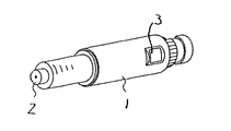
即ち、図11に示すように、先ず穿刺装置1の刺針口2を患者の指先等に当接させる。そして、ボタン3を押す。すると刺針口2から針が高速で突出するとともに瞬時に後退し、指先等に微小な傷をつける。そして、この傷から血液を採取する。   That is, as shown in FIG. 11, the puncture port 2 of the puncture device 1 is first brought into contact with the patient's fingertip or the like. Then, button 3 is pressed. As a result, the needle protrudes from the puncture needle 2 at a high speed and retracts instantaneously, thereby causing a minute scratch on the fingertip or the like. Then, blood is collected from this wound.

次に、図12に示す血糖値を測定する測定装置4を用い、この測定装置4に挿入された血液センサ5に採取した血液を点着する。そうすると、血糖値が表示部6に表示される。この表示部6に表示された血糖値に基づいて、図13示す注射装置7を用い、この注射装置7の設定ボタン8を操作してインスリンの投与量を設定する。   Next, using the measuring device 4 for measuring the blood glucose level shown in FIG. 12, the collected blood is spotted on the blood sensor 5 inserted in the measuring device 4. Then, the blood glucose level is displayed on the display unit 6. Based on the blood glucose level displayed on the display unit 6, the injection device 7 shown in FIG. 13 is used, and the setting button 8 of the injection device 7 is operated to set the dose of insulin.

次に、この注射装置7の注射口9を患者の皮膚に当接させて投与ボタン10を押す。すると、注射口9から針が進出してインスリンを患者に投与する。   Next, the injection port 9 of the injection device 7 is brought into contact with the patient's skin and the administration button 10 is pushed. Then, the needle advances from the injection port 9 to administer insulin to the patient.

なお、この出願の発明に関連する先行技術文献情報としては、例えば、特許文献1、特許文献2が知られている。
特開2002−219114号公報 特開2004−000555号公報
As prior art document information related to the invention of this application, for example, Patent Document 1 and Patent Document 2 are known.
JP 2002-219114 A JP 2004-000555 A

しかしながらこのような従来のインスリンの投与操作は、患者に多大の負担をかけるものであった。 However, such conventional insulin administration operations place a great burden on the patient.

この様子をいま少し説明する。先ず、患者は穿刺装置1で皮膚に傷をつける。そして血液を流出させる。次に皮膚から流出した血液を測定装置4に挿入されたセンサ5に点着する。測定装置4での血液の測定を待って、この測定装置4の表示部6に表示された血糖値の値を正確に記憶し、このとき注射装置7の設定ボタン8を用いて投与量の設定に間違いのないよう細心の注意を払わなければならない。次に、この注射装置7を患者の皮膚に再び当接させてインスリンを投与する。   I will explain this situation a bit now. First, the patient scratches the skin with the puncture device 1. And blood is drained. Next, blood flowing out from the skin is spotted on the sensor 5 inserted into the measuring device 4. Waiting for the measurement of blood by the measuring device 4, the blood glucose level displayed on the display unit 6 of the measuring device 4 is accurately stored, and at this time, the dose is set using the setting button 8 of the injection device 7. You must pay close attention to make sure there is no mistake. Next, insulin is administered by bringing the injection device 7 into contact with the patient's skin again.

以上説明したようにインスリンの投与操作は、細心の注意の下に操作しなければならず、患者に多大の負担をかけるものであった。   As described above, the insulin administration operation must be performed with great care, and places a great burden on the patient.

本発明は、この問題を解決したもので、容易に血液の採取から薬液の投与までの操作ができる薬液投与装置を提供することを目的としたものである。   The present invention has been made to solve this problem, and an object of the present invention is to provide a drug solution administration device that can easily perform operations from blood collection to drug solution administration.

この目的を達成するために本発明の薬液投与装置は、一方が開放するとともに他方が封止された筒体と、この筒体の前記開放側に装着された血液センサと、この血液センサに対して前記封止側に設けられた中空の針と、この針が装着されたカートリッジと、このカートリッジに封入された薬液を押し出す押し出し手段と、前記カートリッジと前記押し出し手段とを一体的に往復運動させる往復運動手段と、前記血液センサからの信号に基づいて血液の性質を測定する測定回路部と、この測定回路部と前記往復手段と前記押し出し手段とを制御する制御部と、この制御部に接続された開始ボタンとを同一筺体内に設け、前記開始ボタンの操作により、前記針の往復運動と、血液の測定動作と、前記薬液の押し出し動作とをするものである。これにより、所期の目的を達成することができる。   In order to achieve this object, a drug solution administration device according to the present invention includes a cylindrical body that is open on one side and sealed on the other side, a blood sensor mounted on the open side of the cylindrical body, and a blood sensor. The hollow needle provided on the sealing side, the cartridge to which the needle is attached, the pushing means for pushing out the chemical solution sealed in the cartridge, and the cartridge and the pushing means are reciprocated integrally. A reciprocating means, a measuring circuit section for measuring blood properties based on a signal from the blood sensor, a control section for controlling the measuring circuit section, the reciprocating means and the pushing means, and a connection to the control section The start button is provided in the same housing, and the reciprocating motion of the needle, the blood measurement operation, and the drug solution push-out operation are performed by operating the start button. Thereby, the intended purpose can be achieved.

以上のように本発明によれば、開始ボタンの押下により自動的に血液の採取と、この採取した血液の性質の測定と、この測定結果に基づいた薬液量の設定と、この薬液の投与をすることができる。即ち、患者は開始ボタンを押下するのみであり、その操作は非常に簡単で容易なものとなり、操作にまつわる負担を著しく軽減することができる。   As described above, according to the present invention, blood is automatically collected by pressing the start button, the property of the collected blood is measured, the amount of the drug solution is set based on the measurement result, and the drug solution is administered. can do. That is, the patient only presses the start button, and the operation becomes very simple and easy, and the burden on the operation can be remarkably reduced.

また、血液を採取するための穿刺装置の機能と、前記血液の性質を測定する測定装置の機能と、薬液を投与するための注射装置の機能とを同一筺体内に有しているので容易に携帯することができる。   In addition, since it has the function of a puncture device for collecting blood, the function of a measuring device for measuring the properties of the blood, and the function of an injection device for administering a drug solution in the same housing, it can be easily Can be carried around.

更に、血液の採取と薬液を投与する針、及びこの針を往復運動させる往復運動手段を共用化することができるので、小型化を実現することができる。   Furthermore, since a needle for collecting blood and administering a drug solution and a reciprocating means for reciprocating the needle can be used in common, a reduction in size can be realized.

(実施の形態1)
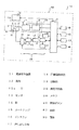
以下、本発明の実施の形態について、図面に基づいて説明する。図1は、実施の形態1における薬液投与装置11のブロック図である。図1において、12は円筒状の筒体であり、この筒体12の一方12aは開放するとともに他方12bは封止されたものである。この筒体12の一方12aには血液センサ(以下、センサという)13が着脱自在に装着されている。そして、このセンサ13の内側(筒体12の他方12b側)には金属製の中空針(以下、針という)14がカートリッジ15に装着されてセンサ13に対向している。このカートリッジ15内にはインスリン(薬液の一例として用いた)16が封入されている。
(Embodiment 1)
Hereinafter, embodiments of the present invention will be described with reference to the drawings. FIG. 1 is a block diagram of a drug solution administration device 11 according to the first embodiment. In FIG. 1, reference numeral 12 denotes a cylindrical cylinder. One of the cylinders 12 is opened and the other 12 b is sealed. A blood sensor (hereinafter referred to as a sensor) 13 is detachably attached to one side 12 a of the cylindrical body 12. A metal hollow needle (hereinafter referred to as a needle) 14 is attached to the cartridge 15 and faces the sensor 13 inside the sensor 13 (on the other 12b side of the cylindrical body 12). Insulin 16 (used as an example of a drug solution) 16 is enclosed in the cartridge 15.

カートリッジ15は押し出し手段17に機械的に連結されており、この押し出し手段17は往復運動手段18に機械的に連結されている。この押し出し手段17と往復運動手段18は夫々制御部19に接続されており、この制御部19で制御される。即ち、押し出し手段17はカートリッジ15内のインスリン16を針14から設定量に基づいて押し出すものであり、往復運動手段18は押し出し手段17と一体的に連結して針14をセンサ13側へ往復運動をさせるものである。   The cartridge 15 is mechanically connected to the pushing means 17, and the pushing means 17 is mechanically connected to the reciprocating means 18. The pushing means 17 and the reciprocating means 18 are connected to a control unit 19 and controlled by the control unit 19. That is, the push-out means 17 pushes out the insulin 16 in the cartridge 15 from the needle 14 based on the set amount, and the reciprocating means 18 is connected integrally with the push-out means 17 to reciprocate the needle 14 toward the sensor 13 side. It is what makes you.

25(25a〜25eで構成されている)はコネクタであり、測定回路部26を形成する切替回路27に接続されている。この切替回路27の出力は電流/電圧変換器28の入力に接続されており、この電流/電圧変換器28の出力はA/D変換器29の入力に接続されている。このA/D変換器29の出力は演算部30の入力に接続されており、この演算部30の出力は液晶で形成された表示部31に接続されている。また、制御部19には演算部30と、切替回路27とが接続されている。また、32は基準電圧源であり切替回路27に接続されている。ここで、切替回路27から基準電圧源32までが測定回路部26であり、センサ13に採取された血液の性質を測定するものである。   Reference numeral 25 (consisting of 25a to 25e) denotes a connector, which is connected to a switching circuit 27 forming the measurement circuit unit 26. The output of the switching circuit 27 is connected to the input of the current / voltage converter 28, and the output of the current / voltage converter 28 is connected to the input of the A / D converter 29. The output of the A / D converter 29 is connected to the input of the calculation unit 30, and the output of the calculation unit 30 is connected to a display unit 31 formed of liquid crystal. In addition, a calculation unit 30 and a switching circuit 27 are connected to the control unit 19. A reference voltage source 32 is connected to the switching circuit 27. Here, the measuring circuit section 26 is from the switching circuit 27 to the reference voltage source 32 and measures the properties of the blood collected by the sensor 13.

35は、センサ供給手段であり、このセンサ供給手段35内にはセンサ13が積層されて収納されている。このセンサ供給手段35は制御部19に接続されており、制御部19の指令でセンサ13を一枚ずつ順次筒体12の一方12aに供給するものである。   Reference numeral 35 denotes sensor supply means, and the sensor 13 is stacked and accommodated in the sensor supply means 35. The sensor supply means 35 is connected to the control unit 19, and supplies the sensors 13 one by one to the one 12 a of the cylindrical body 12 one by one in response to a command from the control unit 19.

36は、当接スイッチ(当接センサの一例として用いた)であり、制御部に19接続されている。この当接スイッチ36は筒体12の一方12a先端の刺針口に隣接して装着されており、皮膚への当接を検出するものである。本実施の形態では当接スイッチとして、機構的に動作するマイクロスイッチを用いたが、これはマイクロスイッチに限ることはなく、光学的に当接を検知するフォトセンサであっても良いし、皮膚の電気抵抗を測定することにより当接を検知するものであっても良い。   Reference numeral 36 denotes a contact switch (used as an example of a contact sensor), which is connected to the control unit 19. The contact switch 36 is mounted adjacent to the puncture opening at the tip of one end 12a of the cylindrical body 12, and detects contact with the skin. In this embodiment, a micro switch that operates mechanically is used as the contact switch. However, this is not limited to a micro switch, and may be a photo sensor that optically detects contact, or skin. The contact may be detected by measuring the electrical resistance.

37は負圧手段であり、その入力は制御部19に接続されるとともに出力は負圧路92を介して筒体12内に接続されている。そして、センサ13の近傍を負圧にすることにより皮膚表面を緊張させる。皮膚を緊張させることにより、針14での穿刺を容易にしたり、血液の流出を助長するものである。   Reference numeral 37 denotes a negative pressure means, whose input is connected to the control unit 19 and whose output is connected to the inside of the cylindrical body 12 via a negative pressure path 92. And the skin surface is tensioned by making the vicinity of the sensor 13 into a negative pressure. By tensioning the skin, puncture with the needle 14 is facilitated, and blood outflow is promoted.

38は制御部19に接続されたメモリであり、演算部30での演算結果や、押し出し手段17の押し出し量(すなわち薬液の投与量)、或いは往復運動手段18の運動量やそのスピードの制御値等を格納するものである。このメモリ38は着脱自在に設けられているので、演算部30で測定した血液の性質(測定日時、血糖値、インスリンの投与量等)が格納されており、そのまま医療機関へ提出して適切な指示を得ることができる。   Reference numeral 38 denotes a memory connected to the control unit 19, the calculation result in the calculation unit 30, the push-out amount of the push-out means 17 (that is, the dose of the drug solution), the exercise amount of the reciprocating means 18, and the control value of its speed Is stored. Since this memory 38 is detachably provided, the blood properties (measurement date and time, blood glucose level, insulin dose, etc.) measured by the calculation unit 30 are stored and submitted to the medical institution as appropriate. You can get directions.

39は、制御部19に接続された警報手段であり、本実施の形態ではブザーで形成している。これは、ブザーに限ることはなく、音声を用いて注意やガイドをしても良く、また、光等を用いても良い。40は、制御部19に接続された開始ボタンであり、一連の操作を開始する指示を与えるものである。   Reference numeral 39 denotes alarm means connected to the control unit 19, which is formed by a buzzer in this embodiment. This is not limited to a buzzer, but may be used for caution and guidance using sound, or light or the like may be used. Reference numeral 40 denotes a start button connected to the control unit 19, which gives an instruction to start a series of operations.

33は制御部19に接続されたタイマであり、測定回路部26での測定時間の管理や、押し出し手段17や往復運動手段18の時間管理をするものである。また、時計機能も有している。   A timer 33 connected to the control unit 19 manages the measurement time in the measurement circuit unit 26 and manages the time of the pushing means 17 and the reciprocating means 18. It also has a clock function.

次に、図2〜図5を用いてセンサ13の説明を行なう。図2は、本実施の形態におけるセンサ13の断面図である。このセンサ13を形成する基体45は、基板46と、この基板46の上面に貼り合わされたスペーサ47と、このスペーサ47の上面に貼り合わされたカバー48とで構成されている。   Next, the sensor 13 will be described with reference to FIGS. FIG. 2 is a cross-sectional view of the sensor 13 in the present embodiment. The base body 45 that forms the sensor 13 includes a substrate 46, a spacer 47 bonded to the upper surface of the substrate 46, and a cover 48 bonded to the upper surface of the spacer 47.

50は、血液の貯留部であり、その容積は0.904μLである。またこの貯留部50は、基板46に設けられた孔46aとスペーサ47に設けられた孔47aに連通して形成されており、下方に向かって開口している。51はこの貯留部50に一方の端が連結された供給路であり、貯留部50に溜められた血液を毛細管現象で検出部52に導く路である。また、この供給路51の他端は空気孔53に連結している。   Reference numeral 50 denotes a blood reservoir, and its volume is 0.904 μL. The reservoir 50 is formed in communication with a hole 46 a provided in the substrate 46 and a hole 47 a provided in the spacer 47, and opens downward. Reference numeral 51 denotes a supply path having one end connected to the storage section 50, and is a path that guides blood stored in the storage section 50 to the detection section 52 by capillary action. The other end of the supply path 51 is connected to the air hole 53.

54は、検出部(図4参照)52上に載置された試薬であって、この試薬54は、0.01〜2.0wt%CMC水溶液に、PQQ−GDHを0.1〜5.0U/センサ、フェリシアン化カリウムを10〜200mM、マルチトールを1〜50mM、タウリンを20〜200mM添加して溶解させて試薬溶液を調整し、これを基板46に形成された検出電極55,57(図4参照)上に滴下し、乾燥させることで形成したものである。   54 is a reagent placed on the detection unit (see FIG. 4) 52. This reagent 54 is prepared by adding 0.1 to 5.0 U of PQQ-GDH in 0.01 to 2.0 wt% CMC aqueous solution. / Sensor, 10 to 200 mM potassium ferricyanide, 1 to 50 mM maltitol, and 20 to 200 mM taurine are added and dissolved to prepare a reagent solution, which is used as detection electrodes 55 and 57 formed on the substrate 46 (FIG. 4). Reference) and formed by dropping and drying.

図3は、センサ13の分解平面図である。図3(c)は、センサ13を構成する長方形をした基板46の平面図であり、その一方の寸法46bは10mmであり、他方の寸法46cは7mmである。この基板46の材質はポリエチレンテレフタレート(PET)であり、その厚さは0.188mm(0.075〜0.250mmの範囲)の物を用いている。   FIG. 3 is an exploded plan view of the sensor 13. FIG. 3C is a plan view of a rectangular substrate 46 constituting the sensor 13, and one dimension 46b is 10 mm and the other dimension 46c is 7 mm. The material of the substrate 46 is polyethylene terephthalate (PET), and a thickness of 0.188 mm (in the range of 0.075 to 0.250 mm) is used.

そして、この基板46の上面には金、白金、パラジウム等を材料として、スパッタリング法或いは蒸着法により導電層を形成し、これをレーザ加工により検出電極55〜58と、この検出電極55〜58から夫々導出された接続電極55a〜58aを一体的に形成している。46aは、基板46の略中央に設けられた孔であり、その直径は2.000mmとしている。この孔46aの壁面は、供給路51より弱い親水性処理をするか、或いはカバー48の上面48eより弱い撥水性処理をすることが好ましい。   Then, a conductive layer is formed on the upper surface of the substrate 46 by using a material such as gold, platinum, palladium, etc. by sputtering or vapor deposition, and this is formed from the detection electrodes 55 to 58 and the detection electrodes 55 to 58 by laser processing. The connection electrodes 55a to 58a respectively led out are integrally formed. 46a is a hole provided in the approximate center of the board | substrate 46, The diameter shall be 2.000 mm. The wall surface of the hole 46 a is preferably subjected to a hydrophilic treatment weaker than that of the supply path 51 or a water repellent treatment weaker than that of the upper surface 48 e of the cover 48.

図3(b)はスペーサ47の平面図であり、一方の寸法47bは8mmである。また、他方の寸法47cは4mmである。そしてその形状は長方形状をしている。47aは、スペーサ47の略中央に設けられた直径2.000mm孔であり、基板46に設けられた孔46aに対応する位置に設けられている。この孔47aの壁面は、供給路51より弱い親水性処理をするか、或いはカバー48の上面48eより弱い撥水性処理をすることが好ましい。   FIG. 3B is a plan view of the spacer 47, and one dimension 47b is 8 mm. The other dimension 47c is 4 mm. The shape is rectangular. 47 a is a hole having a diameter of 2.000 mm provided in the approximate center of the spacer 47, and is provided at a position corresponding to the hole 46 a provided in the substrate 46. The wall surface of the hole 47 a is preferably subjected to a hydrophilic treatment that is weaker than the supply path 51 or a water-repellent treatment that is weaker than the upper surface 48 e of the cover 48.

また、この孔47aから検出部52方向に向かってスリット47eが形成されている。このスリット47eは血液の供給路51を形成するものである。このスリット47eの壁面と、それに対応する前記基板46の上面も親水性処理を行なう。また、このスリット47eの幅47fは0.600mmとし、その長さ47gは2.400mmとして、0.144μLの容積を有する供給路51を形成している。なお、スペーサ47の材質はポリエチレンテレフタレートであり、その厚さは0.100mm(0.050〜0.125mmの範囲)の物を用いている。   A slit 47e is formed from the hole 47a toward the detection unit 52. The slit 47e forms a blood supply path 51. The wall surface of the slit 47e and the corresponding upper surface of the substrate 46 are also subjected to hydrophilic treatment. The slit 47e has a width 47f of 0.600 mm and a length 47g of 2.400 mm to form a supply path 51 having a volume of 0.144 μL. The spacer 47 is made of polyethylene terephthalate and has a thickness of 0.100 mm (in the range of 0.050 to 0.125 mm).

図3(a)はカバー48の平面図である。その形状は、一方の寸法48bは8mmであり、他方の寸法48cは4mmとして長方形状をしている。53は空気孔であり、供給路51の先端部に対応して設けられている。その直径は50μmである。
このカバー48の材質はポリエチレンテレフタレートであり、その厚さは0.075mm(0.050〜0.125mmの範囲)の物を用いている。このカバー48は以下の処理を行なっている。即ち、基体45の上面を形成するカバー48の上面48eは撥水性処理を行なっている。また、供給路51の天面を形成するカバー48の下面側は親水性処理を行なっている。また、貯留部50の天面50aは、供給路51より弱い親水性処理をするか、或いはカバー48の上面48eより弱い撥水性処理をすることが好ましい。本実施の形態では、貯留部50の天面50aは供給路51より弱い親水性処理にするとともに、カバー48の上面48eより弱い撥水性処理を行なっている。
FIG. 3A is a plan view of the cover 48. The shape is rectangular with one dimension 48b being 8 mm and the other dimension 48c being 4 mm. Reference numeral 53 denotes an air hole, which is provided corresponding to the distal end portion of the supply path 51. Its diameter is 50 μm.
The cover 48 is made of polyethylene terephthalate and has a thickness of 0.075 mm (in the range of 0.050 to 0.125 mm). The cover 48 performs the following processing. That is, the upper surface 48e of the cover 48 that forms the upper surface of the base body 45 is subjected to water repellency treatment. Further, the lower surface side of the cover 48 that forms the top surface of the supply path 51 is subjected to hydrophilic treatment. In addition, it is preferable that the top surface 50 a of the storage unit 50 is subjected to a hydrophilic process that is weaker than that of the supply path 51 or a water-repellent process that is weaker than that of the upper surface 48 e of the cover 48. In the present embodiment, the top surface 50 a of the storage unit 50 is subjected to a hydrophilic process that is weaker than the supply path 51 and a water-repellent process that is weaker than the upper surface 48 e of the cover 48.

ここで、親水性を弱にする方法、及び、撥水性を弱にする方法について述べる。先ず、親水性を弱にするには、材料として用いているポリエチレンテレフタレート(PET)の親水性材料を剥がし、ポリエチレンテレフタレートの有する疎水性を強くする。なお、これは、UV(紫外線)を照射して親水性材料を分解することで実現できる。また、貯留部50の天面50aは、ポリエチレンテレフタレート素材の疎水性をそのまま用いることができる。   Here, a method for weakening hydrophilicity and a method for weakening water repellency will be described. First, in order to weaken the hydrophilicity, the hydrophilic material of polyethylene terephthalate (PET) used as a material is peeled off to increase the hydrophobicity of polyethylene terephthalate. This can be realized by decomposing the hydrophilic material by irradiating UV (ultraviolet rays). Moreover, the top surface 50a of the storage part 50 can use the hydrophobicity of a polyethylene terephthalate material as it is.

次に、撥水性についてのべる。撥水性材料を得るには、材料に撥水性材料を混入すれば良い。また、親水性材料の上に適量の撥水性材料を塗布しても良い。なお撥水性を弱にするには、混入する撥水性材料の量でその撥水度を調整することができる。   Next, we will talk about water repellency. In order to obtain a water-repellent material, the material may be mixed with a water-repellent material. Further, an appropriate amount of water repellent material may be applied on the hydrophilic material. In order to weaken the water repellency, the water repellency can be adjusted by the amount of the water repellant material to be mixed.

このような親水性処理或いは撥水性処理をセンサ13に施すには、以下の製造方法による。先ず、予め、カバー48の上面48eには撥水性処理を行なう。また、供給路51の天面となるカバー48の下面には親水性処理を全面に渡って施す。次に、基板46、スペーサ47、カバー48を貼り合わせる。そして、貼り合わせた後に、貯留部50の開口から短波長のUVを照射して、天面50aの親水性材料を分解除去する。   Such a hydrophilic treatment or water repellency treatment is applied to the sensor 13 by the following manufacturing method. First, the upper surface 48e of the cover 48 is previously subjected to water repellency treatment. Further, a hydrophilic treatment is applied to the entire lower surface of the cover 48 serving as the top surface of the supply path 51. Next, the substrate 46, the spacer 47, and the cover 48 are bonded together. And after bonding together, short wavelength UV is irradiated from the opening of the storage part 50, and the hydrophilic material of the top | upper surface 50a is decomposed and removed.

以上のように製造することにより、カバー48の上面48eを撥水性にするとともに、供給路51内を親水性にすることができる。また、貯留部50内部は、供給路51より親水性の弱いもの、或いは上面48eより、撥水性の弱いものを実現することができる。   By manufacturing as described above, the upper surface 48e of the cover 48 can be made water-repellent and the inside of the supply path 51 can be made hydrophilic. In addition, the inside of the storage unit 50 can be realized to be less hydrophilic than the supply path 51 or to be less water-repellent than the upper surface 48e.

また、本実施の形態における各部材の厚みは以下のようになっている。即ち、基板46の厚み(0.188mm)と、スペーサ47の厚み(0.100mm)と、カバー48の厚み(0.075mm)との比は、略1:1.3:2.5となっており、センサ13の薄型化を図りながら、しかも十分な血液を溜める貯留部50を形成することができる。また、スペーサ47の厚み(0.100mm)により、供給路51の毛細管現象の効果も十分に得ることができる。   Moreover, the thickness of each member in this Embodiment is as follows. That is, the ratio of the thickness of the substrate 46 (0.188 mm), the thickness of the spacer 47 (0.100 mm), and the thickness of the cover 48 (0.075 mm) is approximately 1: 1.3: 2.5. In addition, while the thickness of the sensor 13 is reduced, the reservoir 50 that accumulates sufficient blood can be formed. Moreover, the capillary effect of the supply channel 51 can be sufficiently obtained by the thickness of the spacer 47 (0.100 mm).

以下、センサ13における作用効果について説明する。先ず、空気孔53と穿刺孔60の関係に関する作用効果について説明する。本実施の形態におけるセンサ13は、針14によって形成される穿刺孔60(図5参照)の面積より、空気孔53の面積を小さくしたものである。即ち、空気孔53の面積より穿刺孔60の面積の方を大きくすることにより、空気孔53より穿刺孔60の方が血液62の流出に対する抵抗が小さくなる。従って、過剰に採取された血液62があったとしても、その血液62のほとんどは穿刺孔60から流出することになる。このことにより、空気孔53から流出する血液62は極めて少なくなり、この血液62により試薬54を押し流すようなことはない。即ち、試薬54は検出部52から移動することはなく、検出部52において血液62の正確な検査ができる。   Hereinafter, the function and effect of the sensor 13 will be described. First, the effect regarding the relationship between the air hole 53 and the puncture hole 60 is demonstrated. In the sensor 13 in the present embodiment, the area of the air hole 53 is smaller than the area of the puncture hole 60 (see FIG. 5) formed by the needle 14. That is, by making the area of the puncture hole 60 larger than the area of the air hole 53, the puncture hole 60 becomes less resistant to the outflow of blood 62 than the air hole 53. Therefore, even if there is an excessively collected blood 62, most of the blood 62 flows out from the puncture hole 60. As a result, the blood 62 flowing out from the air hole 53 is extremely reduced, and the blood 54 does not cause the reagent 54 to be swept away. That is, the reagent 54 does not move from the detection unit 52, and the blood 62 can be accurately tested in the detection unit 52.

次に、撥水性、親水性の作用効果について説明する。本実施の形態におけるセンサ13は、カバー48の上面48eに撥水性処理が施されているので、空気孔53と穿刺孔60からの血液62の流出は抑制される。従って、無駄な血液62を採取する必要はなく、患者に負担をかけることはない。   Next, the effects of water repellency and hydrophilicity will be described. In the sensor 13 according to the present embodiment, the water repellent treatment is performed on the upper surface 48e of the cover 48, so that the outflow of the blood 62 from the air hole 53 and the puncture hole 60 is suppressed. Therefore, there is no need to collect useless blood 62 and no burden is placed on the patient.

更に、貯留部50は、供給路51より弱い親水性処理か、或いは上面48eより弱い撥水性処理が施されており、貯留部50に貯留された血液62は、一気に律速状態で検出部52に達する。従って、試薬54の溶融性にばらつきが生ずることはなく、正確な血液62の成分を測定することができる。   Furthermore, the reservoir 50 is subjected to a hydrophilic process weaker than the supply path 51 or a water-repellent process weaker than the upper surface 48e, and the blood 62 stored in the reservoir 50 is transferred to the detector 52 in a rate-determining state. Reach. Therefore, there is no variation in the meltability of the reagent 54, and an accurate blood 62 component can be measured.

次に、貯留部50の容積と供給路51の容積の関係における作用効果について説明する。本実施の形態におけるセンサ13は、貯留部50の容積(0.904μL)と供給路51の容積(0.144μL)の比を略6:1としたものであり、貯留部50の容積は供給路51の容積の約6倍の容積を有している。従って、血液62の不足で検査が不正確になることはない。また、貯留部50の容積は必要とする供給路51の容積に対して大き過ぎることはなく、血液62が大量に供給路51を流れて試薬54を押し流すこともない。従って、この面でも血液62の流れが律速状態となり、試薬54の溶解性にばらつきが生ずることはなく、正確な血液62の検査ができる。   Next, the effect in the relationship between the volume of the storage part 50 and the volume of the supply path 51 will be described. The sensor 13 in the present embodiment has a ratio of the volume of the reservoir 50 (0.904 μL) to the volume of the supply channel 51 (0.144 μL) of approximately 6: 1, and the volume of the reservoir 50 is supplied. The volume of the channel 51 is about 6 times. Therefore, the test is not inaccurate due to the lack of blood 62. Further, the volume of the storage unit 50 is not too large with respect to the required volume of the supply path 51, and the blood 62 does not flow through the supply path 51 in a large amount and push away the reagent 54. Therefore, the flow of the blood 62 is in a rate-determining state also in this aspect, so that the solubility of the reagent 54 does not vary and the blood 62 can be accurately inspected.

また、採取する血液62の量は、血液62の検査に必要十分な微小容量に形成されたものであり、供給路容積の約6倍の血液62を採取するのみであり、患者にかける負担を極めて少なくすることができる。なお、正確な測定のために血液62の採取量と、患者への負担を少なくするための血液62の採取量とを勘案して、貯留部50の容積は、供給路51の容積の5倍以上、7倍以下が最適となる。   In addition, the amount of blood 62 to be collected is formed in a micro volume necessary and sufficient for the examination of the blood 62, and only the blood 62 that is about 6 times the volume of the supply channel is collected. It can be very small. Note that the volume of the reservoir 50 is five times the volume of the supply channel 51 in consideration of the amount of blood 62 collected for accurate measurement and the amount of blood 62 collected to reduce the burden on the patient. Above, 7 times or less is optimal.

図4は、センサ13の透視平面図である。基板46上には検出部52を構成する検出電極55,56,57,58が形成されており、これらの検出電極は、例えば順番に作用極、検知極、対極、Hct(ヘマトクリット)極として作用する。そして、これらの検出電極55〜58は、基板46の外周側に形成された接続電極55a,56a,57a,58aに夫々対応して接続されている。そして、これらの接続電極55a〜58aは、コネクタ25(このコネクタ25にはコネクタ25a、25b、25c、25d,25eが含まれる)に夫々接続される。55b〜58b、58cは、夫々対応するコネクタが接触する接触場所であり、基板46の外周近傍に配置されている。   FIG. 4 is a perspective plan view of the sensor 13. Detection electrodes 55, 56, 57, and 58 constituting the detection unit 52 are formed on the substrate 46, and these detection electrodes function, for example, as a working electrode, a detection electrode, a counter electrode, and an Hct (hematocrit) electrode in order. To do. These detection electrodes 55 to 58 are connected to connection electrodes 55a, 56a, 57a, 58a formed on the outer peripheral side of the substrate 46, respectively. These connection electrodes 55a to 58a are connected to the connector 25 (the connector 25 includes connectors 25a, 25b, 25c, 25d, and 25e), respectively. Reference numerals 55 b to 58 b and 58 c are contact locations where the corresponding connectors contact, and are disposed in the vicinity of the outer periphery of the substrate 46.

接触場所58cは接続電極58a内に接触場所58bと共に形成されている。これは接触場所58cと接触場所58bとの導通を測定することにより、センサ13の装着の有無の検知や接続電極55a〜58aの夫々の位置を特定する基準とするためのものである。   The contact location 58c is formed in the connection electrode 58a together with the contact location 58b. This is for measuring the continuity between the contact location 58c and the contact location 58b, thereby detecting whether or not the sensor 13 is mounted and using it as a reference for specifying the positions of the connection electrodes 55a to 58a.

以上のように構成されたセンサ13について、以下にその動作を説明する。図5に示すように、先ず、センサ13を患者の指等の皮膚61に当接させる。そして、針14を矢印59方向に発射させる。そうすると、針14は、貯留部50の天面50aを形成するカバー48を突き破り、このカバー48に穿刺孔60を形成する。そして針14は、この穿刺孔60を介して皮膚61に傷をつける。そうすると、この皮膚61から血液62が流出する。この流出した血液62は貯留部50を満たす。貯留部50を満たした血液62は供給路51に達し、この供給路51の毛細管現象で検出部52へ向かって一気に一定速度で流入する。   The operation of the sensor 13 configured as described above will be described below. As shown in FIG. 5, first, the sensor 13 is brought into contact with the skin 61 such as a patient's finger. Then, the needle 14 is fired in the direction of the arrow 59. Then, the needle 14 breaks through the cover 48 that forms the top surface 50 a of the storage unit 50, and forms a puncture hole 60 in the cover 48. The needle 14 damages the skin 61 through the puncture hole 60. Then, blood 62 flows out from the skin 61. This outflowed blood 62 fills the reservoir 50. The blood 62 that fills the reservoir 50 reaches the supply channel 51 and flows into the detection unit 52 at a constant speed at a stretch by the capillary phenomenon of the supply channel 51.

次に、図1と図4を参照しながら血糖値の測定について説明する。図4において、55b〜58bは接触場所であり、コネクタ25a〜25dと接続されている。血糖値の測定動作では、先ず切替回路27を切換えて、血液成分量を測定するための作用極となる検出電極55を電流/電圧変換器28に接続する。また、血液62の流入を検知するための検知極となる検出電極56を基準電圧源32に接続する。そして、検出電極55及び検出電極56間に一定の電圧を印加する。この状態において、血液62が流入すると、検出電極55,56間に電流が流れる。この電流は、電流/電圧変換器28によって電圧に変換され、その電圧値はA/D変換器29によってデジタル値に変換される。そして、演算部30に向かって出力される。演算部30はそのデジタル値に基づいて血液62が十分に流入したことを検出する。   Next, blood glucose level measurement will be described with reference to FIGS. In FIG. 4, 55b-58b is a contact location and is connected with the connectors 25a-25d. In the blood glucose level measurement operation, first, the switching circuit 27 is switched to connect the detection electrode 55 serving as a working electrode for measuring the blood component amount to the current / voltage converter 28. In addition, a detection electrode 56 serving as a detection electrode for detecting the inflow of blood 62 is connected to the reference voltage source 32. A constant voltage is applied between the detection electrode 55 and the detection electrode 56. In this state, when blood 62 flows in, a current flows between the detection electrodes 55 and 56. This current is converted into a voltage by the current / voltage converter 28, and the voltage value is converted into a digital value by the A / D converter 29. Then, it is output toward the calculation unit 30. The computing unit 30 detects that the blood 62 has sufficiently flowed in based on the digital value.

次に、血液成分であるグルコースの測定が行なわれる。グルコース成分量の測定は、先ず、制御部19の指令により、切替回路27を切換えて、グルコース成分量の測定のための作用極となる検出電極55を電流・電圧変換器28に接続する。また、グルコース成分量の測定のための対極となる検出電極57を基準電圧源32に接続する。   Next, glucose, which is a blood component, is measured. In the measurement of the glucose component amount, first, the switching circuit 27 is switched according to a command from the control unit 19, and the detection electrode 55 serving as a working electrode for measuring the glucose component amount is connected to the current / voltage converter 28. In addition, a detection electrode 57 serving as a counter electrode for measuring the glucose component amount is connected to the reference voltage source 32.

なお、例えば血液中のグルコースとその酸化還元酵素とを一定時間反応させる間は、電流/電圧変換器28及び基準電圧源32をオフにしておく。そして、一定時間(1〜10秒)の経過後に、制御部19の指令により、検出電極55と57間に一定の電圧(0.2〜0.5V)を印加する。そうすると、検出電極55,57間に電流が流れる。この電流は電流/電圧変換器28によって電圧に変換され、その電圧値はA/D変換器29によってデジタル値に変換されて、演算部30に向かって出力される。演算部30はそのデジタル値を基にグルコース成分量に換算する。なお、時間はタイマ33で測定される。   For example, the current / voltage converter 28 and the reference voltage source 32 are turned off while glucose in the blood is reacted with its oxidoreductase for a predetermined time. Then, after a certain time (1 to 10 seconds) has elapsed, a certain voltage (0.2 to 0.5 V) is applied between the detection electrodes 55 and 57 according to a command from the control unit 19. As a result, a current flows between the detection electrodes 55 and 57. This current is converted into a voltage by the current / voltage converter 28, and the voltage value is converted into a digital value by the A / D converter 29 and output to the arithmetic unit 30. The arithmetic unit 30 converts the glucose component amount based on the digital value. The time is measured by the timer 33.

次に、グルコース成分量の測定後、Hct値の測定が行なわれる。Hct値の測定は次のように行なわれる。先ず、制御部19からの指令により切替回路27を切換える。そして、Hct値の測定のための作用極となる検出電極58を電流/電圧変換器28に接続する。また、Hct値の測定のための対極となる検出電極55を基準電圧源32に接続する。   Next, after the glucose component amount is measured, the Hct value is measured. The Hct value is measured as follows. First, the switching circuit 27 is switched by a command from the control unit 19. Then, the detection electrode 58 serving as a working electrode for measuring the Hct value is connected to the current / voltage converter 28. In addition, a detection electrode 55 serving as a counter electrode for measuring the Hct value is connected to the reference voltage source 32.

次に、制御部19の指令により、電流/電圧変換器27及び基準電圧源32から検出電極58と55間に一定の電圧(2V〜3V)を印加する。検出電極58と55間に流れる電流は、電流/電圧変換器28によって電圧に変換され、その電圧値はA/D変換器29によってデジタル値に変換される。そして演算部30に向かって出力される。演算部30はそのデジタル値に基づいてHct値に換算する。   Next, a constant voltage (2 V to 3 V) is applied between the detection electrodes 58 and 55 from the current / voltage converter 27 and the reference voltage source 32 according to a command from the control unit 19. The current flowing between the detection electrodes 58 and 55 is converted into a voltage by the current / voltage converter 28, and the voltage value is converted into a digital value by the A / D converter 29. And it is output toward the calculating part 30. The arithmetic unit 30 converts the digital value into an Hct value.

この測定で得られたHct値とグルコース成分量を用い、予め求めておいた検量線または検量線テーブルを参照して、グルコース成分量をHct値で補正し、その補正された結果をメモリ38に格納するとともに表示部31に表示する。このように補正された測定データに基づいてインスリンの投与量が自動的に設定される。このように、患者が自ら投与するインスリンの量を注射装置に設定する必要は無く、設定の煩わしさは無い。また、人為手段を介さずにインスリンの量を設定することができるので、設定ミスを防止することができる。   Using the Hct value and the glucose component amount obtained in this measurement, referring to a calibration curve or a calibration curve table obtained in advance, the glucose component amount is corrected with the Hct value, and the corrected result is stored in the memory 38. It is stored and displayed on the display unit 31. The dose of insulin is automatically set based on the measurement data corrected in this way. Thus, there is no need to set the amount of insulin that the patient himself administers to the injection device, and there is no troublesome setting. In addition, since the amount of insulin can be set without going through artificial means, setting errors can be prevented.

次に、センサ13を自動供給するセンサ供給手段35について説明する。図6(a)において、63は直方体形状をしたセンサ13の収納部であり、この収納部63にはセンサ13が積層して収納される。63aは押圧板であり、バネ63bでセンサ13を供給板64方向へ押圧している。63cは収納部63の上面に設けられた開口であり、センサ13の消費に応じてこの開口63cからセンサ13を供給する。また、63dは押圧板63aに連結されたつまみであり、このつまみ63dを矢印63e方向に移動して開口63cからセンサ13を供給する。なお、このつまみ63dの位置でセンサ13の残量を知ることができる。なお、収納部63を透明部材で形成してセンサ13の残量を検知しても良い。   Next, the sensor supply means 35 that automatically supplies the sensor 13 will be described. In FIG. 6A, reference numeral 63 denotes a storage portion for the sensor 13 having a rectangular parallelepiped shape, and the sensors 13 are stacked and stored in the storage portion 63. Reference numeral 63a denotes a pressing plate that presses the sensor 13 toward the supply plate 64 with a spring 63b. 63 c is an opening provided on the upper surface of the storage unit 63, and the sensor 13 is supplied from the opening 63 c according to consumption of the sensor 13. Reference numeral 63d denotes a knob connected to the pressing plate 63a. The knob 63d is moved in the direction of the arrow 63e to supply the sensor 13 from the opening 63c. The remaining amount of the sensor 13 can be known at the position of the knob 63d. Note that the storage unit 63 may be formed of a transparent member to detect the remaining amount of the sensor 13.

センサ13は一枚ずつ供給板64に形成された供給孔69aにバネ63bの圧力で供給される。65は供給板64を回転させるモータであり、制御器66を介して制御部19に接続されている。また、67は透過型の光学センサであり、供給板64の回転角を検出するものである。この光学センサ67の出力は、制御器66を介して制御部19に接続されている。   The sensors 13 are supplied one by one to the supply holes 69a formed in the supply plate 64 with the pressure of the spring 63b. A motor 65 rotates the supply plate 64 and is connected to the controller 19 via a controller 66. Reference numeral 67 denotes a transmissive optical sensor that detects the rotation angle of the supply plate 64. The output of the optical sensor 67 is connected to the control unit 19 via the controller 66.

25(25a〜25e)は、センサ13の接続場所55b〜58b、58cに接触するように設けられたコネクタであり、測定孔69b近傍に設けられている。そしてこのコネクタ25は、測定回路部26の切替回路27に接続されている。   Reference numeral 25 (25a to 25e) denotes a connector provided so as to contact the connection places 55b to 58b and 58c of the sensor 13, and is provided in the vicinity of the measurement hole 69b. The connector 25 is connected to the switching circuit 27 of the measurement circuit unit 26.

図6(b)は、供給板64の平面図である。この供給板64は円形をしており、収納部63の開口側に回転自在に装着されている。この供給板64は、中心64eから等角度に4個の長方形状をしたセンサ挿入孔69(このセンサ挿入孔69には供給孔69a、測定孔69b、排出孔69dが含まれる)が設けられている。このセンサ挿入孔69は長方形状をしたセンサ13が嵌入するものであり、このセンサ挿入孔69に挿入されたセンサ13の接続場所55b〜58b、58cは夫々コネクタ25a〜25eに接続されることになる。   FIG. 6B is a plan view of the supply plate 64. The supply plate 64 has a circular shape and is rotatably mounted on the opening side of the storage portion 63. The supply plate 64 is provided with four rectangular sensor insertion holes 69 at equal angles from the center 64e (the sensor insertion hole 69 includes a supply hole 69a, a measurement hole 69b, and a discharge hole 69d). Yes. The sensor insertion hole 69 is for receiving the sensor 13 having a rectangular shape, and the connection locations 55b to 58b and 58c of the sensor 13 inserted into the sensor insertion hole 69 are connected to the connectors 25a to 25e, respectively. Become.

また、この4個のセンサ挿入孔69に対応して4個の検出孔64fが設けられている。この供給板64の中心64eにはモータ65が減速機構を介して連結されている。そして、モータ65でこの供給板64を4分の1回転ずつ回転させるものである。この4分の1の回転は光学センサ67が検出孔64fを検出することにより行われる。   Further, four detection holes 64 f are provided corresponding to the four sensor insertion holes 69. A motor 65 is connected to the center 64e of the supply plate 64 via a speed reduction mechanism. Then, the supply plate 64 is rotated by a quarter turn by the motor 65. The quarter rotation is performed when the optical sensor 67 detects the detection hole 64f.

この供給板64は矢印68方向に回転し、図において供給板64の上方に位置するセンサ挿入孔69がセンサ13の供給孔69aとなり、下方に位置するセンサ挿入孔69がセンサ13の測定孔69bとなる。また、この測定孔69bから90度の角度にあるセンサ挿入孔69がセンサ13の排出孔69dとなる。   The supply plate 64 rotates in the direction of the arrow 68. In the drawing, the sensor insertion hole 69 located above the supply plate 64 becomes the supply hole 69a of the sensor 13, and the sensor insertion hole 69 located below is the measurement hole 69b of the sensor 13. It becomes. In addition, the sensor insertion hole 69 at an angle of 90 degrees from the measurement hole 69 b becomes the discharge hole 69 d of the sensor 13.

従って、供給孔69aで収納部63から供給されたセンサ13は、測定孔69bまで回転して、血液62の採取をし、その性質が測定される。測定が終了したら4分の1回転して排出孔69dの位置で排出されることになる。このようにして、収納部63内にあるセンサ13を順次測定孔69bに供給することができる。   Accordingly, the sensor 13 supplied from the storage portion 63 through the supply hole 69a rotates to the measurement hole 69b, collects blood 62, and the property thereof is measured. When the measurement is completed, it is rotated by a quarter and discharged at the position of the discharge hole 69d. In this manner, the sensors 13 in the storage unit 63 can be sequentially supplied to the measurement holes 69b.

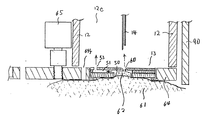
図7は、薬液投与装置11の断面図である。図7において、90は、筒体12とセンサ供給手段35と負圧手段37と測定回路部26を含む電気回路91が収納された筺体である。センサ供給手段35は筒体12の一方12a近傍の上面に装着されており、供給板64は一方12aの開口を塞ぐように装着されている。従って、通常時において、針14の先端は外部からは見えず恐怖心は軽減される。   FIG. 7 is a cross-sectional view of the drug solution administration device 11. In FIG. 7, reference numeral 90 denotes a housing in which an electric circuit 91 including a cylindrical body 12, a sensor supply unit 35, a negative pressure unit 37, and a measurement circuit unit 26 is accommodated. The sensor supply means 35 is mounted on the upper surface of the cylindrical body 12 near the one 12a, and the supply plate 64 is mounted so as to close the opening of the one 12a. Therefore, at the normal time, the tip of the needle 14 cannot be seen from the outside, and fear is reduced.

負圧手段37は、筒体12の上面であってセンサ供給手段35の後方に装着されている。そして、この負圧手段37の負圧出力は筒体12に設けられた負圧路92を通って筒体12内に連結しており、センサ13の近傍を負圧にする。この負圧手段37は図9に示すように筒体12の内部12cを負圧にする。また、供給板64に設けられた検出孔64fを介してセンサ13の下面を負圧にする。従って、皮膚61はセンサ13にピッタリと密着するので、血液62が流れ出して皮膚61を汚すことはない。また、負圧手段37は、穿刺前においては空気孔53を介して貯留部50内を負圧にする。従って、貯留部50内の皮膚61が緊張状態となり、穿刺が容易となる。更に、穿刺後においては穿刺孔60を介して貯留部50を負圧にし、血液62を吸引し皮膚61からの血液62の流出を加速させる。   The negative pressure means 37 is mounted on the upper surface of the cylinder 12 and behind the sensor supply means 35. And the negative pressure output of this negative pressure means 37 is connected in the cylinder 12 through the negative pressure path 92 provided in the cylinder 12, and makes the vicinity of the sensor 13 a negative pressure. As shown in FIG. 9, the negative pressure means 37 makes the inside 12c of the cylindrical body 12 have a negative pressure. In addition, the lower surface of the sensor 13 is set to a negative pressure through a detection hole 64 f provided in the supply plate 64. Therefore, since the skin 61 is closely attached to the sensor 13, the blood 62 does not flow out and does not contaminate the skin 61. Moreover, the negative pressure means 37 makes the inside of the storage part 50 a negative pressure via the air hole 53 before puncturing. Therefore, the skin 61 in the reservoir 50 is in a tensioned state, and puncturing is facilitated. Further, after the puncture, the reservoir 50 is set to a negative pressure through the puncture hole 60, the blood 62 is sucked, and the outflow of the blood 62 from the skin 61 is accelerated.

電気回路91は、負圧手段37の更に後方に装着されており、センサ供給手段35と負圧手段37と押し出し手段17と往復運動手段18を制御する。   The electric circuit 91 is mounted further rearward of the negative pressure means 37 and controls the sensor supply means 35, the negative pressure means 37, the pushing means 17, and the reciprocating means 18.

次に、図7に戻り筒体12内を中心に説明する。15はインスリン16が封入された円筒形状のカートリッジであり、このカートリッジ15の先端15aと後端15bは夫々ゴムで形成された栓15c、15dが挿入されている。   Next, returning to FIG. 7, the inside of the cylindrical body 12 will be mainly described. Reference numeral 15 denotes a cylindrical cartridge in which insulin 16 is sealed. Plugs 15c and 15d made of rubber are inserted into the front end 15a and the rear end 15b of the cartridge 15, respectively.

71は、カートリッジ15が挿入されるカートリッジホルダであり、このカートリッジホルダ71にカートリッジ15が着脱自在に装着される。このカートリッジ15の先端側には円形のキャップ72が装着されている。そして、このキャップ72の略中央には針14が装着されている。この針14の根元側は、カートリッジ15の先端15aに挿入された栓15cを貫通してインスリン16まで達している。   Reference numeral 71 denotes a cartridge holder into which the cartridge 15 is inserted, and the cartridge 15 is detachably attached to the cartridge holder 71. A circular cap 72 is attached to the front end side of the cartridge 15. The needle 14 is attached to the approximate center of the cap 72. The base side of the needle 14 reaches the insulin 16 through the plug 15c inserted into the tip 15a of the cartridge 15.

73は、インスリン16を針14方向に押し出す動力として用いるDC(直流)モータであり、このモータ73の回転軸はギアで形成された減速機構89を介してシャフト74に連結している。このシャフト74の表面には、雄ねじ74aが形成されている。   Reference numeral 73 denotes a DC (direct current) motor used as power for pushing the insulin 16 in the direction of the needle 14, and the rotation shaft of the motor 73 is connected to the shaft 74 via a speed reduction mechanism 89 formed of a gear. A male screw 74 a is formed on the surface of the shaft 74.

75はシャフト74に連結して設けられたエンコーダであり、76はこのエンコーダ75の回転(回転量及び回転速度)を検出する透過型のセンサである。なお、このセンサ76は透過型である必要は無く、反射型センサであっても良い。また、エンコーダ75は、図8に示すように円板形状をしている。75aは回転の中心であり、75bは外周近傍の内側の同心円上に設けられた孔である。この孔75bは等間隔に12個設けている。モータ73が回転することにより、このエンコーダ75が回転する。そうすると、センサ76からはこの孔75bを透過する度に光信号がパルス信号に変換されて出力される。従って、このパルス信号を計数することで、モータ73の回転数やシャフト74の回転数(回転角を含む)、並びに回転速度を容易かつ精密に計測することができる。このエンコーダ75とセンサ76とで回転数検出部17aを構成している。   Reference numeral 75 denotes an encoder connected to the shaft 74, and reference numeral 76 denotes a transmission type sensor that detects the rotation (rotation amount and rotation speed) of the encoder 75. The sensor 76 does not need to be a transmission type, and may be a reflection type sensor. The encoder 75 has a disk shape as shown in FIG. 75a is the center of rotation, and 75b is a hole provided on an inner concentric circle near the outer periphery. Twelve holes 75b are provided at equal intervals. As the motor 73 rotates, the encoder 75 rotates. Then, each time the sensor 76 passes through the hole 75b, the optical signal is converted into a pulse signal and output. Therefore, by counting the pulse signals, the rotational speed of the motor 73, the rotational speed of the shaft 74 (including the rotational angle), and the rotational speed can be measured easily and precisely. The encoder 75 and the sensor 76 constitute a rotation speed detector 17a.

図7に戻って、77は、ピストン78に連結して固定されたナットであり、このナット77の内側にはシャフト74に形成された雄ねじ74aと螺合する雌ねじ77aが設けられている。従って、モータ73が正方向に回転することにより、シャフト74の回転運動がナット77と協働して、ピストン78を矢印79に示す前進する方向(針14の装着された方向)に移動させる。そして、その移動する距離はセンサ76から出力されるパルス信号を計数することで測定することができる。また、移動する速度はセンサ76から出力されるパルス信号の密度(周波数)で測定することができる。従って、ピストン78の移動量を精密にコントロールすることができる。この雄ねじ74aと雌ねじ77aとで回転数/直進運動変換部17bを構成している。   Returning to FIG. 7, reference numeral 77 denotes a nut connected and fixed to the piston 78. Inside the nut 77, a female screw 77 a that is screwed with a male screw 74 a formed on the shaft 74 is provided. Therefore, when the motor 73 rotates in the forward direction, the rotational movement of the shaft 74 cooperates with the nut 77 to move the piston 78 in the forward direction indicated by the arrow 79 (the direction in which the needle 14 is attached). The moving distance can be measured by counting pulse signals output from the sensor 76. The moving speed can be measured by the density (frequency) of the pulse signal output from the sensor 76. Therefore, the amount of movement of the piston 78 can be precisely controlled. The male screw 74a and the female screw 77a constitute a rotational speed / linear motion conversion portion 17b.

ピストン78の先端は、カートリッジ15に挿入された栓15dに当接している。この栓15dはカートリッジ15の後端15b方向から先端15aの方向に摺動可能に設けられている。従って、ピストン78が矢印79方向に前進することにとり、カートリッジ15内の栓15dが矢印79方向に押される。このようにして、精密なインスリン16の量を中空の針14の先端から患者に投与することができる。なお、モータ73を逆回転させれば、ピストン78は矢印79と反対方向に後退する。   The tip of the piston 78 is in contact with the stopper 15d inserted into the cartridge 15. The stopper 15d is slidable from the rear end 15b of the cartridge 15 toward the front end 15a. Accordingly, when the piston 78 moves forward in the direction of the arrow 79, the stopper 15d in the cartridge 15 is pushed in the direction of the arrow 79. In this way, a precise amount of insulin 16 can be administered to the patient from the tip of the hollow needle 14. If the motor 73 is rotated in the reverse direction, the piston 78 moves backward in the direction opposite to the arrow 79.

80は、モータ73が固定されたフレームであり、このフレーム80はモータ73を囲うように設けられている。ここで、モータ73とシャフト74とナット77とピストン78とエンコーダ75とセンサ76と押し出しを制御する制御部19の一部(図1参照)とでインスリン16を押し出す押し出し手段17を形成している。   Reference numeral 80 denotes a frame on which the motor 73 is fixed. The frame 80 is provided so as to surround the motor 73. Here, the motor 73, the shaft 74, the nut 77, the piston 78, the encoder 75, the sensor 76, and a part of the control unit 19 that controls the extrusion (see FIG. 1) form the push-out means 17 that pushes out the insulin 16. .

81は、筒体12に固定されたDCモータである。このDCモータ81は、フレーム80に往復運動を与える動力として用いるものであり、カートリッジ15と針14もフレーム80に従って往復運動する。モータ81の回転軸はギアで形成された減速機構(図示せず)を介してシャフト82に連結している。このシャフト82の表面には、雄ねじ82aが形成されている。   Reference numeral 81 denotes a DC motor fixed to the cylindrical body 12. The DC motor 81 is used as power for giving a reciprocating motion to the frame 80, and the cartridge 15 and the needle 14 also reciprocate according to the frame 80. The rotation shaft of the motor 81 is connected to the shaft 82 via a speed reduction mechanism (not shown) formed of gears. A male screw 82 a is formed on the surface of the shaft 82.

83はシャフト82に連結して設けられたエンコーダであり、84はこのエンコーダ83の回転(回転量及び回転速度)を検出する透過型のセンサである。なお、このセンサ84も透過型である必要は無く、反射型センサであっても良い。また、エンコーダ83は、図8に示したエンコーダ75と同様であり、モータ81が回転することにより、このエンコーダ83が回転する。そうすると、エンコーダ83の回転情報(回転量及び回転速度)がセンサ84からパルス信号となって出力される。従って、このパルス信号を計数することで、モータ81の回転数やシャフト82の回転数(回転角を含む)、並びに回転速度を計測することができる。このエンコーダ83とセンサ84とで回転数検出部18aを構成している。   Reference numeral 83 denotes an encoder connected to the shaft 82, and reference numeral 84 denotes a transmission type sensor that detects the rotation (rotation amount and rotation speed) of the encoder 83. The sensor 84 does not need to be a transmission type, and may be a reflection type sensor. The encoder 83 is the same as the encoder 75 shown in FIG. 8, and the encoder 83 rotates when the motor 81 rotates. Then, rotation information (rotation amount and rotation speed) of the encoder 83 is output from the sensor 84 as a pulse signal. Therefore, by counting this pulse signal, the rotational speed of the motor 81, the rotational speed of the shaft 82 (including the rotational angle), and the rotational speed can be measured. The encoder 83 and the sensor 84 constitute a rotation speed detector 18a.

85は、フレーム80に固定されたナットであり、このナット85の内側にはシャフト82に形成された雄ねじ82aと螺合する雌ねじ85aが設けられている。従って、フレーム80の移動量を精密にコントロールすることができる。この雄ねじ82aと雌ねじ85aとで回転数/直進運動変換部18bを構成している。   Reference numeral 85 denotes a nut fixed to the frame 80, and an internal thread 85 a that engages with an external thread 82 a formed on the shaft 82 is provided inside the nut 85. Therefore, the movement amount of the frame 80 can be precisely controlled. The male screw 82a and the female screw 85a constitute a rotational speed / straight-motion conversion unit 18b.

従って、モータ81が正方向に回転することにより、シャフト82の回転運動がナット85と協働して、フレーム80を矢印86で示す前進する方向に移動させる。そして、その移動する距離はセンサ84から出力されるパルス信号の数で検出することができる。また、移動する速度はセンサ84から出力されるパルス信号の密度(周波数)で検出することができる。   Accordingly, when the motor 81 rotates in the forward direction, the rotational movement of the shaft 82 cooperates with the nut 85 to move the frame 80 in the forward direction indicated by the arrow 86. The moving distance can be detected by the number of pulse signals output from the sensor 84. The moving speed can be detected by the density (frequency) of the pulse signal output from the sensor 84.

即ち、シャフト82の先端は、ナット85を介してフレーム80と連結しているので、モータ81が正回転すると、フレーム80が矢印86方向に前進することになり、押し出し手段17全体を前進させることになる。逆に、モータ81が逆回転すると、フレーム80が矢印86と反対方向に進む(即ち後退)ことになり、押し出し手段17全体を後退させることになる。このようにして、モータ81を正回転、或いは逆回転させることにより、押し出し手段17及びこの押し出し手段17に連結されたカートリッジ15や針14を精密に往復運動させることができる。ここで、モータ81とシャフト82とナット85とエンコーダ83とセンサ84と往復運動を制御する制御部19の一部(図1参照)とで往復運動手段18を形成している。   That is, since the tip of the shaft 82 is connected to the frame 80 via the nut 85, when the motor 81 rotates in the forward direction, the frame 80 moves forward in the direction of the arrow 86, and the entire pushing means 17 moves forward. become. On the contrary, when the motor 81 rotates in the reverse direction, the frame 80 moves in the direction opposite to the arrow 86 (that is, retreats), and the entire pushing means 17 is retreated. Thus, by rotating the motor 81 forward or backward, the pushing means 17 and the cartridge 15 and the needle 14 connected to the pushing means 17 can be precisely reciprocated. Here, the motor 81, the shaft 82, the nut 85, the encoder 83, the sensor 84, and a part of the control unit 19 that controls the reciprocating motion (see FIG. 1) form the reciprocating means 18.

また、フレーム80から外側に向かってフレーム凸部80aが形成されており、一方筒体12には、フレーム凸部80aが嵌入するレール87が設けられている。従って、フレーム凸部80aはレール87上を滑動する。即ち、フレーム80(カートリッジ15と針14も同じ)は、矢印86方向或いはその逆方向に往復運動する。このときフレーム凸部80aとレール87の効果により、筒体12との間において回転運動をすることはない。   Further, a frame convex portion 80a is formed outward from the frame 80, and a rail 87 into which the frame convex portion 80a is fitted is provided on the cylindrical body 12. Accordingly, the frame convex portion 80a slides on the rail 87. That is, the frame 80 (the cartridge 15 and the needle 14 are the same) reciprocates in the direction of the arrow 86 or in the opposite direction. At this time, due to the effects of the frame convex portion 80a and the rail 87, there is no rotational movement between the cylindrical body 12.

また同様に、ピストン78から外側に向かってピストン凸部78aが形成されており、一方フレーム80には、ピストン凸部78aが嵌入するピストンガイド88が設けられている。従って、ピストン凸部78aはピストンガイド88上を滑動する。即ち、ピストン78は、矢印79の方向或いはその逆方向に往復運動する。このときピストン凸部78aとピストンガイド88の効果により、フレーム80との間において回転運動をすることはない。   Similarly, a piston convex portion 78a is formed outward from the piston 78, and on the other hand, the frame 80 is provided with a piston guide 88 into which the piston convex portion 78a is fitted. Accordingly, the piston protrusion 78 a slides on the piston guide 88. That is, the piston 78 reciprocates in the direction of the arrow 79 or the opposite direction. At this time, due to the effects of the piston protrusion 78a and the piston guide 88, there is no rotational movement between the frame 80.

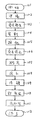
以上のように構成された薬液投与装置11について、以下その動作を説明する。図10において、先ず、ステップ101において薬液投与装置11の電源スイッチをオンする。そして、ステップ102の準備ステップに移り、薬液投与装置11の動作種類の表示として表示部31には「血糖値の測定」の表示がなされる。   About the chemical | medical solution administration apparatus 11 comprised as mentioned above, the operation | movement is demonstrated below. In FIG. 10, first, in step 101, the power switch of the drug solution administration device 11 is turned on. Then, the process proceeds to the preparation step of Step 102, where “Measurement of blood glucose level” is displayed on the display unit 31 as an indication of the operation type of the drug solution administration device 11.

このとき制御部19では、センサ供給手段35に設けられたコネクタ25d、25eによる短絡信号を検知してセンサ13有り状態の検知と、押し出し手段17の押し出し量によりインスリン16の残量の検知と、当接スイッチ36の皮膚61への当接検知の確認を行なう。これらの検知確認のうち一つでも条件が揃わないときは警報手段39で警報するとともに、表示部31にその内容を表示する。全ての条件が揃った状態で「OK」の旨を表示部31に表示する。そして、患者は「OK」の表示を確認した後、開始ボタン40を押下する。すると、ステップ103の負圧発生ステップに移行する。   At this time, the control unit 19 detects the short-circuit signal by the connectors 25d and 25e provided in the sensor supply means 35 to detect the presence of the sensor 13 and the remaining amount of the insulin 16 based on the pushing amount of the pushing means 17. The contact detection of the contact switch 36 to the skin 61 is confirmed. When even one of these detection confirmations is not met, the alarm means 39 warns and displays the contents on the display unit 31. When all the conditions are met, “OK” is displayed on the display unit 31. Then, after confirming the display of “OK”, the patient presses the start button 40. Then, the process proceeds to the negative pressure generation step of step 103.

ステップ103では、負圧手段37を動作させて負圧路92を介してセンサ13の近傍に負圧を加える。この負圧で皮膚61とセンサ13の下面とを密着させる。また、センサ13の貯留部50内は空気孔53を介して負圧を加える。このようにして皮膚61の表面を負圧にして皮膚を緊張状態にすることにより、穿刺を容易にし、ステップ104の穿刺ステップに移行する。   In step 103, the negative pressure means 37 is operated to apply a negative pressure in the vicinity of the sensor 13 via the negative pressure path 92. The skin 61 and the lower surface of the sensor 13 are brought into close contact with this negative pressure. Further, a negative pressure is applied to the inside of the storage unit 50 of the sensor 13 through the air hole 53. In this way, the surface of the skin 61 is made negative pressure so that the skin is in a tension state, thereby facilitating the puncture, and the process proceeds to the puncture step of Step 104.

ステップ104では、モータ81を正回転させて、往復運動手段18を高速(0.05sec)で小距離(10mm)前進させる。針14はセンサ13のカバー48を突き破り、皮膚61に傷をつける。そして、ステップ105の採血ステップに移行する。
ステップ105では、前記傷から血液62が流出し、この血液62で貯留部50が満たされる。このとき、貯留部50の天面50aには針14で穿刺孔60が形成されるので、負圧はこの穿刺孔60を介して貯留部50内を更に負圧にし、血液の流出を助長する。貯留部50を満たした血液62は毛細管現象で供給路51を律速(一定の速度)状態で検出部52に至る。そして、ステップ106の負圧停止ステップに移行する。
In step 104, the motor 81 is rotated forward, and the reciprocating means 18 is advanced at a high speed (0.05 sec) by a small distance (10 mm). The needle 14 breaks through the cover 48 of the sensor 13 and damages the skin 61. Then, the process proceeds to the blood collection step of Step 105.
In step 105, blood 62 flows out from the wound, and the reservoir 50 is filled with this blood 62. At this time, since the puncture hole 60 is formed by the needle 14 on the top surface 50a of the reservoir 50, the negative pressure further reduces the inside of the reservoir 50 through the puncture hole 60, and promotes the outflow of blood. . The blood 62 that fills the reservoir 50 reaches the detector 52 in a state of rate-limiting (constant speed) in the supply path 51 by capillary action. And it transfers to the negative pressure stop step of step 106.

ステップ106では、血液62が検出電極56に到達したことを検出して負圧手段37の負圧動作を停止させる。従って、血液62の採取量は最低となり、患者にかける負担は最低となる。負圧動作を停止させた後、ステップ107の測定ステップに移行する。ここで、予め定められた時間が経過しても、検出電極56で血液62の流入が検出できないときは、警報手段39を動作させ警報するともに表示部31にその旨と今後の処置を表示する。また、これまでのステップにおいて、当接スイッチ36がオフになった場合も同様に警報手段39を動作させ警報するともに表示部31にその旨と今後の処置を表示する。   In step 106, the negative pressure operation of the negative pressure means 37 is stopped by detecting that the blood 62 has reached the detection electrode 56. Therefore, the amount of blood 62 collected is minimum, and the burden on the patient is minimum. After the negative pressure operation is stopped, the process proceeds to the measurement step of Step 107. Here, if the inflow of blood 62 cannot be detected by the detection electrode 56 even after a predetermined time has elapsed, the alarm means 39 is operated to give an alarm, and that effect and future treatment are displayed on the display unit 31. . Further, in the steps so far, even when the contact switch 36 is turned off, the alarm means 39 is similarly operated to give an alarm, and that effect and future measures are displayed on the display unit 31.

ステップ107では、先ずグルコースの測定を行う。即ち、血液中のグルコースとグルコース酸化還元酵素とを一定時間反応させた後、検出電極55を作用極、検出電極57を対極として、前記両検出電極55,57間に電圧を印加する。そして、グルコースの測定を行う。   In step 107, glucose is first measured. That is, after reacting glucose in blood with glucose oxidoreductase for a certain period of time, a voltage is applied between the detection electrodes 55 and 57 with the detection electrode 55 as a working electrode and the detection electrode 57 as a counter electrode. Then, glucose is measured.

次に、Hct値の測定をする。検出電極58を作用極、検出電極55を対極として、両検出電極55,58間に電圧を印加する。このことにより、Hct値に依存する電流が検出できる。従って、この電流に基づきHct値を測定する。   Next, the Hct value is measured. A voltage is applied between the detection electrodes 55 and 58 using the detection electrode 58 as a working electrode and the detection electrode 55 as a counter electrode. As a result, a current depending on the Hct value can be detected. Therefore, the Hct value is measured based on this current.

そして最後に、血液成分の補正を行なう。即ち、測定した前記Hct値を用いて、先に得られたグルコース量を補正する。この補正されたグルコース量はメモリ38に格納される。なお、このステップ107の後に負圧手段37を停止しても良い。この場合、薬液投与装置11が血液62の測定中の時間皮膚61に当接しているので、薬液投与装置11の動揺は少なく、試薬54による化学反応が安定するので、精密で安定した測定が可能となる。次にステップ108の薬液投与ステップに移る。   Finally, the blood component is corrected. That is, the previously obtained glucose amount is corrected using the measured Hct value. The corrected glucose amount is stored in the memory 38. Note that the negative pressure means 37 may be stopped after this step 107. In this case, since the medicinal solution administration device 11 is in contact with the skin 61 during the measurement of the blood 62, the medicinal solution administration device 11 is less shaken and the chemical reaction by the reagent 54 is stabilized, so that precise and stable measurement is possible. It becomes. Next, the process proceeds to a chemical solution administration step of step 108.

ステップ108では、モータ81を正回転させて、往復運動手段18を低速(0.2sec)で小距離(10mm)前進させる。そして、モータ73を正回転させて、押し出し手段17を低速(0.2sec)で前記メモリ38に格納されたグルコース量に基づいた距離前進させる。このことにより、精密にインスリン16の量が投与される。しかも、メモリ38に格納された測定値を自動的に用いるので、患者による投与量の設定ミスは生じない。次に、ステップ109の待機ステップに移行する。
ステップ109では、穿刺した状態で5秒間待機する。これは投与したインスリン16が確実に患者の体内に移行する時間である。そして、ステップ110の針14の後退ステップに移行する。
In step 108, the motor 81 is rotated forward, and the reciprocating means 18 is advanced at a low speed (0.2 sec) by a small distance (10 mm). Then, the motor 73 is rotated forward, and the pushing means 17 is moved forward by a distance based on the amount of glucose stored in the memory 38 at a low speed (0.2 sec). This allows a precise dose of insulin 16 to be administered. In addition, since the measurement values stored in the memory 38 are automatically used, there is no dose setting mistake by the patient. Next, the process proceeds to the standby step of step 109.
In step 109, the process waits for 5 seconds with puncturing. This is the time when the administered insulin 16 is surely transferred into the patient's body. Then, the process proceeds to the step of retracting the needle 14 in step 110.

ステップ110では、モータ81を逆転させて、往復運動手段18を低速(0.2sec)で大距離(20mm)後退させる。そして、ステップ111の後処理ステップに移行する。   In step 110, the motor 81 is reversely rotated, and the reciprocating means 18 is moved backward by a large distance (20 mm) at a low speed (0.2 sec). And it transfers to the post-processing step of step 111.

ステップ111では、測定及び投与した日時、血糖値、投与量等を表示部31に表示する。そして、センサ供給手段35では、供給板64を4分の1回転させて、使用済みのセンサ13を排出(廃棄)されるとともに、未使用のセンサ13を供給孔64aに供給(測定孔64bにも未使用のセンサ13が供給される)される。そして、ステップ112の電源をオフするステップ112の終了ステップに移行する。   In step 111, the date and time of measurement and administration, blood glucose level, dosage, etc. are displayed on the display unit 31. In the sensor supply means 35, the supply plate 64 is rotated by a quarter to discharge (discard) the used sensor 13 and supply the unused sensor 13 to the supply hole 64a (to the measurement hole 64b). (An unused sensor 13 is also supplied). Then, the process proceeds to the end step of step 112 in which the power is turned off in step 112.

ステップ112では、薬液投与装置11の電源をオフして全ての動作を終了する。なお、薬液投与装置11に送信部を設けておけば、その結果を医療機関等に送信することができる。また、その他にも血液62の採取、測定、薬液の投与中に異常が発生した場合は、警報手段39で患者に警告するとともに、表示部31にその対処方法を表示するようになっている。   In step 112, the power of the medicinal solution administration device 11 is turned off and all operations are finished. In addition, if the transmission part is provided in the chemical | medical solution administration apparatus 11, the result can be transmitted to a medical institution etc. In addition, when an abnormality occurs during collection, measurement, and administration of a drug solution, blood is alerted to the patient by the alarm means 39, and the coping method is displayed on the display unit 31.

以上説明したように、患者は開始ボタン40を押下するのみであり、その操作は非常に簡単で容易なものとなり、操作にまつわる負担を著しく軽減することができる。
また、血液62を採取するための穿刺装置の機能と、前記血液62の性質を測定する測定装置の機能と、インスリン16を投与するための注射装置の機能とを同一筺体90内に有しているので容易に携帯することができる。
As described above, the patient only presses the start button 40, and the operation becomes very simple and easy, and the burden on the operation can be remarkably reduced.
Further, the same housing 90 has a function of a puncture device for collecting blood 62, a function of a measuring device for measuring the properties of blood 62, and a function of an injection device for administering insulin 16. It can be easily carried.

更に、血液62の採取と薬液を投与する針14、及びこの針14を往復運動させる往復運動手段18を共用化することができるので、小型化を実現することができる。
以上、グルコースの測定を例に説明したが、グルコースの測定の他に乳酸値やコレステロールの血液成分の測定にも有用である。
Further, since the needle 14 for collecting the blood 62 and administering the drug solution and the reciprocating means 18 for reciprocating the needle 14 can be used in common, the size can be reduced.
As described above, the measurement of glucose has been described as an example. However, in addition to the measurement of glucose, it is also useful for the measurement of blood components of lactic acid level and cholesterol.

本発明にかかる薬液投与装置は、操作が容易であり十分な訓練を受け難い患者が使用する医療装置等として有用である。   The drug solution administration device according to the present invention is useful as a medical device or the like used by a patient who is easy to operate and who is not easily trained.

本発明の実施の形態1における薬液投与装置のブロック図The block diagram of the chemical | medical solution administration apparatus in Embodiment 1 of this invention 同、センサの断面図Cross section of the sensor (a)は同、基板の平面図 (b)は同、スペーサの平面図 (c)は同、カバーの平面図(A) is the same plan view of the substrate (b) is the same plan view of the spacer (c) is the same plan view of the cover 同、センサの透視平面図Same perspective plan view of sensor 同、動作説明のためのセンサとその周辺の説明図Same as above, explanatory diagram of sensor and its surroundings for operation explanation (a)は同、センサ供給手段の断面図 (b)は同、供給板の平面図(A) is a cross-sectional view of the sensor supply means. (B) is a plan view of the supply plate. 同、血液投与装置の断面図Same as above, sectional view of blood administration device 同、エンコーダの平面図Same as above, top view of encoder 同、血液投与装置の要部断面図Same as above, sectional view of main part of blood administration device 同、動作フローチャートSame operation flowchart 従来の穿刺装置の外観斜視図External perspective view of conventional puncture device 同、センサと測定装置の平面図Same as above, top view of sensor and measuring device 同、注射装置の外観斜視図Same as above, perspective view of injection device

符号の説明Explanation of symbols

11 薬液投与装置
12 筒体
12a 一方
13 センサ
14 針
15 カートリッジ
16 インスリン
17 押し出し手段
18 往復運動手段
19 制御部
26 測定回路部
38 メモリ
40 開始ボタン
62 血液
90 筺体
DESCRIPTION OF SYMBOLS 11 Chemical solution administration apparatus 12 Cylinder 12a One side 13 Sensor 14 Needle 15 Cartridge 16 Insulin 17 Pushing means 18 Reciprocating means 19 Control part 26 Measurement circuit part 38 Memory 40 Start button 62 Blood 90 Body

Claims (18)

一方が開放するとともに他方が封止された筒体と、この筒体の前記開放側に装着された血液センサと、この血液センサに対して前記封止側に設けられた中空の針と、この針が装着されたカートリッジと、このカートリッジに封入された薬液を押し出す押し出し手段と、前記カートリッジと前記押し出し手段とを一体的に往復運動させる往復運動手段と、前記血液センサからの信号に基づいて血液の性質を測定する測定回路部と、この測定回路部と前記往復手段と前記押し出し手段とを制御する制御部と、この制御部に接続された開始ボタンとを同一筺体内に設け、前記開始ボタンの操作により、前記針の往復運動と、血液の測定動作と、前記薬液の押し出し動作とをする薬液投与装置。 A cylinder with one open and the other sealed; a blood sensor mounted on the open side of the cylinder; a hollow needle provided on the sealing side with respect to the blood sensor; and A cartridge equipped with a needle, an extruding means for extruding a medicinal solution sealed in the cartridge, a reciprocating means for integrally reciprocating the cartridge and the extruding means, and blood based on a signal from the blood sensor A measurement circuit unit for measuring the properties of the sensor, a control unit for controlling the measurement circuit unit, the reciprocating unit, and the pushing unit, and a start button connected to the control unit. The drug solution administration device which performs the reciprocating motion of the needle, the blood measurement operation, and the drug solution push-out operation by the above operations. 血液センサは、基体と、この基体に設けられるとともに下方へ向かって開口した血液の貯留部と、この貯留部に一方の端が連結されるとともに毛細管現象で前記血液を検出部に供給する供給路と、この供給路の他方の端に設けられた空気孔と、前記検出部を形成する複数の検出電極と、前記検出部に載置された試薬とから成る請求項1に記載の薬液投与装置。 The blood sensor includes a base body, a blood storage section that is provided on the base body and that opens downward, and one supply end connected to the storage section and supplies the blood to the detection section by capillary action. The medicinal-solution administration device according to claim 1, comprising an air hole provided at the other end of the supply path, a plurality of detection electrodes forming the detection unit, and a reagent placed on the detection unit. . 貯留部の容積と供給路の容積の比を略6対1とした請求項2に記載の薬液投与装置。 The medicinal-solution administration device according to claim 2, wherein the ratio of the volume of the reservoir and the volume of the supply path is approximately 6 to 1. 基体の上面は撥水性にするとともに供給路は親水性とした請求項2に記載の薬液投与装置。 The drug solution administration device according to claim 2, wherein the upper surface of the substrate is water-repellent and the supply path is hydrophilic. 中空針によって形成される穿刺孔の面積より、空気孔の面積を小さくした請求項2に記載の薬液投与装置。 The drug solution administration device according to claim 2, wherein the area of the air hole is smaller than the area of the puncture hole formed by the hollow needle. 血液センサの近傍を負圧にする負圧手段が設けられた請求項2に記載の薬液投与装置。 The medicinal-solution administration device according to claim 2, further comprising negative pressure means for making negative pressure in the vicinity of the blood sensor. 空気孔を介して貯留部に負圧を加える請求項6に記載の薬液投与装置。 The chemical | medical solution administration apparatus of Claim 6 which applies a negative pressure to a storage part via an air hole. 複数枚の血液センサが収納されるとともに、この血液センサを筒体の開放側へ順次供給するセンサ供給手段が設けられた請求項2に記載の薬液投与装置。 The medicinal-solution administration device according to claim 2, wherein a plurality of blood sensors are housed, and sensor supply means for sequentially supplying the blood sensors to the open side of the cylinder is provided. センサ供給手段に血液センサが供給される供給板を設け、この供給板に前記血液センサが嵌入するセンサ挿入孔が設けられた請求項8に記載の薬液投与装置。 9. The drug solution administration device according to claim 8, wherein a supply plate for supplying a blood sensor is provided in the sensor supply means, and a sensor insertion hole into which the blood sensor is fitted is provided in the supply plate. 測定した血液の性質に対応する薬液の投与量のデータを有するメモリを前記制御部に接続するとともに、このメモリは着脱自在とした請求項1に記載の薬液投与装置。 The medicinal-solution administration device according to claim 1, wherein a memory having medicinal-solution dosage data corresponding to the measured blood property is connected to the control unit, and the memory is detachable. 針が出入りする刺針口に隣接して患者の皮膚への当接を検知する当接センサが制御部に接続された請求項1に記載の薬液投与装置。 The medicinal-solution administration device according to claim 1, wherein a contact sensor that detects contact with the patient's skin is connected to the control unit adjacent to the puncture needle port through which the needle enters and exits. 押し出し手段は、第1のモータと、この第1のモータの回転軸とカートリッジの後端との間に設けられた第1の回転数/直進運動変換部と、前記第1のモータの回転数を検出する第1の回転数検出部とからなる請求項1に記載の薬液投与装置。 The push-out means includes a first motor, a first rotational speed / linear motion conversion portion provided between the rotation shaft of the first motor and the rear end of the cartridge, and the rotational speed of the first motor. The medicinal-solution administration device according to claim 1, further comprising: a first rotation speed detection unit that detects 往復運動手段は、第2のモータと、この第2のモータと針との間に設けられた第2の回転数/直進運動変換部と、前記第2のモータの回転数を検出する第2の回転数検出部とからなる請求項12に記載の薬液投与装置。 The reciprocating means includes a second motor, a second rotational speed / linear motion converting portion provided between the second motor and the needle, and a second speed detecting the rotational speed of the second motor. The chemical | medical solution administration apparatus of Claim 12 which consists of these. 異常を警報する警報手段が制御部に接続された請求項1に記載の薬液投与装置。 The drug solution administration device according to claim 1, wherein alarm means for alarming abnormality is connected to the control unit. 患者の皮膚に傷をつける穿刺ステップと、この穿刺ステップの後で血液を採取する採血ステップと、この採血ステップの後で前記採取した血液の性質を測定する測定ステップと、この測定ステップの後で再度穿刺し、前記測定ステップにより測定された測定データに基づいて薬液を投与する投与ステップとを有した請求項1に記載の薬液投与装置を制御する制御方法。 A puncturing step for damaging the skin of the patient, a blood sampling step for collecting blood after the puncturing step, a measuring step for measuring the properties of the collected blood after the blood sampling step, and after the measuring step The control method for controlling the drug solution administration device according to claim 1, further comprising an administration step of puncturing again and administering a drug solution based on the measurement data measured in the measurement step. 投与ステップにおいては、薬液の投与後予め定められた時間待機した後に針を後退させる請求項15に記載の制御方法。 16. The control method according to claim 15, wherein in the administration step, the needle is retracted after waiting for a predetermined time after administration of the drug solution. 採血ステップの前に血液センサ近傍に負圧を加える負圧発生ステップを挿入し、採血ステップと測定ステップとの間に前記負圧の印加を停止する負圧停止ステップとを設けた請求項15に記載の制御方法。 16. The negative pressure stop step for inserting a negative pressure generation step for applying a negative pressure in the vicinity of the blood sensor before the blood collection step and stopping the application of the negative pressure between the blood collection step and the measurement step is provided. The control method described. 穿刺ステップの前に血液センサの有無と薬液の有無を検出する準備ステップを設けた請求項15に記載の制御方法。

The control method according to claim 15, further comprising a preparatory step for detecting presence / absence of a blood sensor and presence / absence of a chemical solution before the puncturing step.

JP2006022041A 2006-01-31 2006-01-31 Chemical solution administration device and control method thereof Expired - Fee Related JP4802737B2 (en)

Priority Applications (1)

Application Number Priority Date Filing Date Title
JP2006022041A JP4802737B2 (en) 2006-01-31 2006-01-31 Chemical solution administration device and control method thereof

Applications Claiming Priority (1)

Application Number Priority Date Filing Date Title
JP2006022041A JP4802737B2 (en) 2006-01-31 2006-01-31 Chemical solution administration device and control method thereof

Publications (2)

Publication Number Publication Date
JP2007202632A true JP2007202632A (en) 2007-08-16
JP4802737B2 JP4802737B2 (en) 2011-10-26

Family

ID=38482644

Family Applications (1)

Application Number Title Priority Date Filing Date
JP2006022041A Expired - Fee Related JP4802737B2 (en) 2006-01-31 2006-01-31 Chemical solution administration device and control method thereof

Country Status (1)

Country Link
JP (1) JP4802737B2 (en)

Cited By (13)

* Cited by examiner, † Cited by third party
Publication number Priority date Publication date Assignee Title
JP2010051720A (en) * 2008-08-29 2010-03-11 Jms Co Ltd Transfusion device
WO2010056878A2 (en) * 2008-11-14 2010-05-20 Pepex Biomedical, Llc Electrochemical sensor module
KR101186909B1 (en) 2011-06-10 2012-10-08 한국과학기술원 Blood collection module of blood sugar, measurement module, measurement device, measurement method using the same, and recording medium thereof
US8506740B2 (en) 2008-11-14 2013-08-13 Pepex Biomedical, Llc Manufacturing electrochemical sensor module
US8951377B2 (en) 2008-11-14 2015-02-10 Pepex Biomedical, Inc. Manufacturing electrochemical sensor module
US9044178B2 (en) 2007-08-30 2015-06-02 Pepex Biomedical, Llc Electrochemical sensor and method for manufacturing
US9459228B2 (en) 2007-08-30 2016-10-04 Pepex Biomedical, Inc. Electrochemical sensor and method for manufacturing
US9504162B2 (en) 2011-05-20 2016-11-22 Pepex Biomedical, Inc. Manufacturing electrochemical sensor modules
JP2017169988A (en) * 2016-03-25 2017-09-28 テルモ株式会社 Medical solution administration device and image display program
US10034629B2 (en) 2011-01-06 2018-07-31 James L. Say Sensor module with enhanced capillary flow
US11045124B2 (en) 2014-06-04 2021-06-29 Pepex Biomedical, Inc. Electrochemical sensors and methods for making electrochemical sensors using advanced printing technology
JP2021119988A (en) * 2014-08-06 2021-08-19 レプリセル ライフ サイエンシーズ インコーポレイテッド Injection devices
US11224367B2 (en) 2012-12-03 2022-01-18 Pepex Biomedical, Inc. Sensor module and method of using a sensor module

Citations (5)

* Cited by examiner, † Cited by third party
Publication number Priority date Publication date Assignee Title
JP2002219114A (en) * 2001-01-26 2002-08-06 Matsushita Electric Works Ltd Blood collecting device
JP2004000555A (en) * 2002-04-25 2004-01-08 Matsushita Electric Ind Co Ltd Dosage determination support device, syringe, and health care support system
JP2005110712A (en) * 2003-10-02 2005-04-28 Matsushita Electric Ind Co Ltd Blood component analysis sensor
JP2005177071A (en) * 2003-12-18 2005-07-07 Matsushita Electric Ind Co Ltd Electric injector
WO2005077441A2 (en) * 2004-02-18 2005-08-25 Ares Trading S.A. Hand-held electronically controlled injection device for injecting liquid medications

Patent Citations (5)

* Cited by examiner, † Cited by third party
Publication number Priority date Publication date Assignee Title
JP2002219114A (en) * 2001-01-26 2002-08-06 Matsushita Electric Works Ltd Blood collecting device
JP2004000555A (en) * 2002-04-25 2004-01-08 Matsushita Electric Ind Co Ltd Dosage determination support device, syringe, and health care support system
JP2005110712A (en) * 2003-10-02 2005-04-28 Matsushita Electric Ind Co Ltd Blood component analysis sensor
JP2005177071A (en) * 2003-12-18 2005-07-07 Matsushita Electric Ind Co Ltd Electric injector
WO2005077441A2 (en) * 2004-02-18 2005-08-25 Ares Trading S.A. Hand-held electronically controlled injection device for injecting liquid medications

Cited By (21)

* Cited by examiner, † Cited by third party
Publication number Priority date Publication date Assignee Title
US9044178B2 (en) 2007-08-30 2015-06-02 Pepex Biomedical, Llc Electrochemical sensor and method for manufacturing
US11150212B2 (en) 2007-08-30 2021-10-19 Pepex Biomedical, Inc. Electrochemical sensor and method for manufacturing
US11016052B2 (en) 2007-08-30 2021-05-25 Pepex Biomedical Inc. Electrochemical sensor and method for manufacturing
US9746440B2 (en) 2007-08-30 2017-08-29 Pepex Biomedical, Llc Electrochemical sensor and method for manufacturing
US9459228B2 (en) 2007-08-30 2016-10-04 Pepex Biomedical, Inc. Electrochemical sensor and method for manufacturing
JP2010051720A (en) * 2008-08-29 2010-03-11 Jms Co Ltd Transfusion device
US8506740B2 (en) 2008-11-14 2013-08-13 Pepex Biomedical, Llc Manufacturing electrochemical sensor module
US10278632B2 (en) 2008-11-14 2019-05-07 Pepex Biomedical, LLC. Electrochemical sensor module
US9445755B2 (en) * 2008-11-14 2016-09-20 Pepex Biomedical, Llc Electrochemical sensor module
WO2010056878A2 (en) * 2008-11-14 2010-05-20 Pepex Biomedical, Llc Electrochemical sensor module
US8951377B2 (en) 2008-11-14 2015-02-10 Pepex Biomedical, Inc. Manufacturing electrochemical sensor module
US20110270061A1 (en) * 2008-11-14 2011-11-03 Pepex Biomedical, Llc Electrochemical sensor module
WO2010056878A3 (en) * 2008-11-14 2010-08-26 Pepex Biomedical, Llc Electrochemical sensor module
US10034629B2 (en) 2011-01-06 2018-07-31 James L. Say Sensor module with enhanced capillary flow
US9504162B2 (en) 2011-05-20 2016-11-22 Pepex Biomedical, Inc. Manufacturing electrochemical sensor modules
KR101186909B1 (en) 2011-06-10 2012-10-08 한국과학기술원 Blood collection module of blood sugar, measurement module, measurement device, measurement method using the same, and recording medium thereof
US11224367B2 (en) 2012-12-03 2022-01-18 Pepex Biomedical, Inc. Sensor module and method of using a sensor module
US11045124B2 (en) 2014-06-04 2021-06-29 Pepex Biomedical, Inc. Electrochemical sensors and methods for making electrochemical sensors using advanced printing technology
JP2021119988A (en) * 2014-08-06 2021-08-19 レプリセル ライフ サイエンシーズ インコーポレイテッド Injection devices
JP7159386B2 (en) 2014-08-06 2022-10-24 レプリセル ライフ サイエンシーズ インコーポレイテッド injection device
JP2017169988A (en) * 2016-03-25 2017-09-28 テルモ株式会社 Medical solution administration device and image display program

Also Published As

Publication number Publication date
JP4802737B2 (en) 2011-10-26

Similar Documents

Publication Publication Date Title
JP4802737B2 (en) Chemical solution administration device and control method thereof
RU2360248C2 (en) Integrated measuring instrument for sample testing
US8057404B2 (en) Blood sensor, blood testing apparatus, and method for controlling blood testing apparatus
EP1997432B1 (en) Blood test device
EP1997434B1 (en) Blood inspection device
CN101346101B (en) Blood test apparatus
US7998087B2 (en) Blood test apparatus and blood test method
RU2343833C2 (en) Integral sample gauge
US7976478B2 (en) Blood test apparatus and method of controlling the same
US8556828B2 (en) Blood test device
US20080200838A1 (en) Wearable, programmable automated blood testing system
JP5047194B2 (en) Blood test equipment
CN1407871A (en) Body fluid measuring apparatus with lancet and lancet holder used for the measuring apparatus
JP2007330510A (en) Blood test device
JP4952078B2 (en) Blood test equipment
JP5011936B2 (en) Blood test equipment
JP2008067743A (en) Blood examination device
JP2009039203A (en) Blood testing apparatus

Legal Events

Date Code Title Description
A621 Written request for application examination

Free format text: JAPANESE INTERMEDIATE CODE: A621

Effective date: 20090127

RD01 Notification of change of attorney

Free format text: JAPANESE INTERMEDIATE CODE: A7421

Effective date: 20091127

A977 Report on retrieval

Free format text: JAPANESE INTERMEDIATE CODE: A971007

Effective date: 20101209

A131 Notification of reasons for refusal

Free format text: JAPANESE INTERMEDIATE CODE: A131

Effective date: 20101214

A521 Request for written amendment filed

Free format text: JAPANESE INTERMEDIATE CODE: A523

Effective date: 20110202

A02 Decision of refusal

Free format text: JAPANESE INTERMEDIATE CODE: A02

Effective date: 20110412

A521 Request for written amendment filed

Free format text: JAPANESE INTERMEDIATE CODE: A523

Effective date: 20110602

A911 Transfer to examiner for re-examination before appeal (zenchi)

Free format text: JAPANESE INTERMEDIATE CODE: A911

Effective date: 20110614

TRDD Decision of grant or rejection written
A01 Written decision to grant a patent or to grant a registration (utility model)

Free format text: JAPANESE INTERMEDIATE CODE: A01

Effective date: 20110712

A01 Written decision to grant a patent or to grant a registration (utility model)

Free format text: JAPANESE INTERMEDIATE CODE: A01

A61 First payment of annual fees (during grant procedure)

Free format text: JAPANESE INTERMEDIATE CODE: A61

Effective date: 20110725

R151 Written notification of patent or utility model registration

Ref document number: 4802737

Country of ref document: JP

Free format text: JAPANESE INTERMEDIATE CODE: R151

FPAY Renewal fee payment (event date is renewal date of database)

Free format text: PAYMENT UNTIL: 20140819

Year of fee payment: 3

S111 Request for change of ownership or part of ownership

Free format text: JAPANESE INTERMEDIATE CODE: R313113

R350 Written notification of registration of transfer

Free format text: JAPANESE INTERMEDIATE CODE: R350

S111 Request for change of ownership or part of ownership

Free format text: JAPANESE INTERMEDIATE CODE: R313113

R350 Written notification of registration of transfer

Free format text: JAPANESE INTERMEDIATE CODE: R350

S111 Request for change of ownership or part of ownership

Free format text: JAPANESE INTERMEDIATE CODE: R313113

R350 Written notification of registration of transfer

Free format text: JAPANESE INTERMEDIATE CODE: R350

R250 Receipt of annual fees

Free format text: JAPANESE INTERMEDIATE CODE: R250

R250 Receipt of annual fees

Free format text: JAPANESE INTERMEDIATE CODE: R250

R250 Receipt of annual fees

Free format text: JAPANESE INTERMEDIATE CODE: R250

S533 Written request for registration of change of name

Free format text: JAPANESE INTERMEDIATE CODE: R313533

R350 Written notification of registration of transfer

Free format text: JAPANESE INTERMEDIATE CODE: R350

R250 Receipt of annual fees

Free format text: JAPANESE INTERMEDIATE CODE: R250

R250 Receipt of annual fees

Free format text: JAPANESE INTERMEDIATE CODE: R250

R250 Receipt of annual fees

Free format text: JAPANESE INTERMEDIATE CODE: R250

LAPS Cancellation because of no payment of annual fees